EP3765715B1 - Locking spacer assembly, blade assembly and method for installing a locking spacer - Google Patents
Locking spacer assembly, blade assembly and method for installing a locking spacer Download PDFInfo
- Publication number
- EP3765715B1 EP3765715B1 EP18723138.6A EP18723138A EP3765715B1 EP 3765715 B1 EP3765715 B1 EP 3765715B1 EP 18723138 A EP18723138 A EP 18723138A EP 3765715 B1 EP3765715 B1 EP 3765715B1
- Authority
- EP
- European Patent Office
- Prior art keywords
- piece
- side piece
- mid
- locking spacer
- bolt
- Prior art date
- Legal status (The legal status is an assumption and is not a legal conclusion. Google has not performed a legal analysis and makes no representation as to the accuracy of the status listed.)
- Active
Links
Images


Classifications
-
- F—MECHANICAL ENGINEERING; LIGHTING; HEATING; WEAPONS; BLASTING
- F01—MACHINES OR ENGINES IN GENERAL; ENGINE PLANTS IN GENERAL; STEAM ENGINES
- F01D—NON-POSITIVE DISPLACEMENT MACHINES OR ENGINES, e.g. STEAM TURBINES
- F01D5/00—Blades; Blade-carrying members; Heating, heat-insulating, cooling or antivibration means on the blades or the members
- F01D5/30—Fixing blades to rotors; Blade roots ; Blade spacers
- F01D5/32—Locking, e.g. by final locking blades or keys
-
- F—MECHANICAL ENGINEERING; LIGHTING; HEATING; WEAPONS; BLASTING
- F01—MACHINES OR ENGINES IN GENERAL; ENGINE PLANTS IN GENERAL; STEAM ENGINES
- F01D—NON-POSITIVE DISPLACEMENT MACHINES OR ENGINES, e.g. STEAM TURBINES
- F01D5/00—Blades; Blade-carrying members; Heating, heat-insulating, cooling or antivibration means on the blades or the members
- F01D5/30—Fixing blades to rotors; Blade roots ; Blade spacers
- F01D5/3023—Fixing blades to rotors; Blade roots ; Blade spacers of radial insertion type, e.g. in individual recesses
- F01D5/303—Fixing blades to rotors; Blade roots ; Blade spacers of radial insertion type, e.g. in individual recesses in a circumferential slot
- F01D5/3038—Fixing blades to rotors; Blade roots ; Blade spacers of radial insertion type, e.g. in individual recesses in a circumferential slot the slot having inwardly directed abutment faces on both sides
-
- F—MECHANICAL ENGINEERING; LIGHTING; HEATING; WEAPONS; BLASTING
- F05—INDEXING SCHEMES RELATING TO ENGINES OR PUMPS IN VARIOUS SUBCLASSES OF CLASSES F01-F04
- F05D—INDEXING SCHEME FOR ASPECTS RELATING TO NON-POSITIVE-DISPLACEMENT MACHINES OR ENGINES, GAS-TURBINES OR JET-PROPULSION PLANTS
- F05D2230/00—Manufacture
- F05D2230/60—Assembly methods
- F05D2230/64—Assembly methods using positioning or alignment devices for aligning or centring, e.g. pins
- F05D2230/644—Assembly methods using positioning or alignment devices for aligning or centring, e.g. pins for adjusting the position or the alignment, e.g. wedges or eccenters
-
- F—MECHANICAL ENGINEERING; LIGHTING; HEATING; WEAPONS; BLASTING
- F05—INDEXING SCHEMES RELATING TO ENGINES OR PUMPS IN VARIOUS SUBCLASSES OF CLASSES F01-F04
- F05D—INDEXING SCHEME FOR ASPECTS RELATING TO NON-POSITIVE-DISPLACEMENT MACHINES OR ENGINES, GAS-TURBINES OR JET-PROPULSION PLANTS
- F05D2250/00—Geometry
- F05D2250/10—Two-dimensional
- F05D2250/11—Two-dimensional triangular
-
- F—MECHANICAL ENGINEERING; LIGHTING; HEATING; WEAPONS; BLASTING
- F05—INDEXING SCHEMES RELATING TO ENGINES OR PUMPS IN VARIOUS SUBCLASSES OF CLASSES F01-F04
- F05D—INDEXING SCHEME FOR ASPECTS RELATING TO NON-POSITIVE-DISPLACEMENT MACHINES OR ENGINES, GAS-TURBINES OR JET-PROPULSION PLANTS
- F05D2250/00—Geometry
- F05D2250/20—Three-dimensional
- F05D2250/23—Three-dimensional prismatic
-
- F—MECHANICAL ENGINEERING; LIGHTING; HEATING; WEAPONS; BLASTING
- F05—INDEXING SCHEMES RELATING TO ENGINES OR PUMPS IN VARIOUS SUBCLASSES OF CLASSES F01-F04
- F05D—INDEXING SCHEME FOR ASPECTS RELATING TO NON-POSITIVE-DISPLACEMENT MACHINES OR ENGINES, GAS-TURBINES OR JET-PROPULSION PLANTS
- F05D2250/00—Geometry
- F05D2250/20—Three-dimensional
- F05D2250/28—Three-dimensional patterned
- F05D2250/281—Three-dimensional patterned threaded
-
- F—MECHANICAL ENGINEERING; LIGHTING; HEATING; WEAPONS; BLASTING
- F05—INDEXING SCHEMES RELATING TO ENGINES OR PUMPS IN VARIOUS SUBCLASSES OF CLASSES F01-F04
- F05D—INDEXING SCHEME FOR ASPECTS RELATING TO NON-POSITIVE-DISPLACEMENT MACHINES OR ENGINES, GAS-TURBINES OR JET-PROPULSION PLANTS
- F05D2260/00—Function
- F05D2260/30—Retaining components in desired mutual position
- F05D2260/31—Retaining bolts or nuts
-
- F—MECHANICAL ENGINEERING; LIGHTING; HEATING; WEAPONS; BLASTING
- F05—INDEXING SCHEMES RELATING TO ENGINES OR PUMPS IN VARIOUS SUBCLASSES OF CLASSES F01-F04
- F05D—INDEXING SCHEME FOR ASPECTS RELATING TO NON-POSITIVE-DISPLACEMENT MACHINES OR ENGINES, GAS-TURBINES OR JET-PROPULSION PLANTS
- F05D2260/00—Function
- F05D2260/30—Retaining components in desired mutual position
- F05D2260/36—Retaining components in desired mutual position by a form fit connection, e.g. by interlocking
Definitions
- This invention relates generally to a locking spacer assembly, in particular, a locking spacer assembly configured to fill a final spacer slot in a disk groove between platforms of adjacent blades of a blade assembly in an industrial gas turbine engine. 2.
- the invention also relates to a corresponding blade assembly, and to a method for installing a locking spacer assembly into a final spacer slot in a disk groove between platforms of adjacent blades of a blade assembly.
- An industrial gas turbine engine typically includes a compressor for compressing air, a combustor for mixing the compressed air with fuel and igniting the mixture, a turbine section for producing mechanical power, and a generator for converting the mechanical power to an electrical power.
- the compressor and the turbine section include a plurality of blades that are attached on a rotor. The blades are arranged in rows axially spaced apart along the rotor and circumferentially attached to a periphery of a rotor disk.
- FIG. 1 illustrates a schematic perspective view of a portion of a blade assembly 100.
- the blade assembly 100 includes a plurality of blades 120 that are attached to a rotor disk 140.
- Each blade 120 includes a platform 122 and a root 124 extending radially inward from the platform 122.
- the blades 120 may be installed to the rotor disk 140 by inserting the roots 124 of the blades 120 into a disk groove 142 one at a time. The blades 120 then may be rotated until the roots 124 of the blade 120 engage the disk groove 142.
- a final spacer slot 144 is remained in the disk groove 142 between the platforms 122 of adjacent blades 120.
- the final spacer slot 144 may not be filled with the blade 120 because there is not sufficient space for insertion and rotation.
- a locking spacer assembly is typically inserted into the final spacer slot 144 to lock the blades 120 to the rotor disk 140.
- a conventional locking spacer assembly typically includes a plurality of pieces, such as side pieces, middle piece, bolt and nut.
- the conventional locking spacer assembly may experience uncertainties during assembly. For example, the conventional locking spacer assembly may require the bolt to carry a centrifugal load of the locking spacer components. Such arrangement may create undesirable failure mode and small safety margin. Additionally, manufacture cost of the conventional locking spacer assembly may be high due to geometric complexity and numbers of the components of the locking spacer assembly. There is a need to provide a simple, reliable and low cost locking spacer assembly.
- aspects of the present invention relate to a locking spacer assembly, in particular, a locking spacer assembly configured to fill a final spacer slot in a disk groove between platforms of adjacent blades of a blade assembly in an industrial gas turbine engine.
- a locking spacer assembly configured to fill a final spacer slot in a disk groove between platforms of adjacent blades of a blade assembly.
- the locking spacer assembly comprises a first side piece.
- the locking spacer assembly comprises a second side piece.
- the locking spacer assembly comprises a mid piece configured to be disposed between an inner surface of the first side piece and an inner surface of the second side piece.
- the locking spacer assembly comprises a bolt configured to be disposed into the mid piece. The bolt is configured to position the mid piece in a radial position in an assembled state.
- the mid piece is configured to contact the first side piece and the second side piece in the assembled state to prevent an axial movement of the first side piece and an axial movement of the second side piece, wherein the mid piece comprises a base and a hollow cylindrical body, wherein the hollow cylindrical body radially penetrates through the base and radially extends upwardly from the base, and wherein the bolt is threaded within the hollow cylindrical body.
- a blade assembly comprising a rotor disk comprising a disk groove.
- the blade assembly comprises a plurality of blades inserted in the disk groove. Each of the blades comprises a platform. A final spacer slot is formed in the disk groove between platforms of adjacent blades.
- the blade assembly comprises a locking spacer according to the invention.
- a method for installing a locking spacer assembly into a final spacer slot in a disk groove between platforms of adjacent blades of a blade assembly comprises a first side piece, a second side piece, a mid piece and a bolt.
- the method comprises disposing the bolt into the mid piece.
- the method comprises placing the mid piece and the bolt disposed within the mid piece into the disk groove.
- the method comprises placing the first side piece and the second side piece into the disk groove one after another such that the mid piece is disposed between an inner surface of the first side piece and an inner surface of the second side piece.
- the method comprises positioning the mid piece in a radial position in an assembled state by the bolt such that the mid piece contacts the first side piece and the second side piece in the assembled state, wherein the second side piece comprises a recess formed at an edge of a top surface and the inner surface.
- FIG. 1 illustrates a schematic perspective view of a portion of a blade assembly 100 showing a final spacer slot 144 in a disk groove 142 between platforms 122 of adjacent blades 120.
- the final spacer slot 144 may have a circumferential width 146 and an axial length 148.
- the blade assembly 100 may be a compressor blade assembly or a turbine blade assembly.
- the final spacer slot 144 may be filled by inventive embodiments of a locking spacer assembly 200 as shown in FIGs. 2-9 , which are described in more detail below.
- the locking spacer assembly 200 may be installed into the final spacer slot 144 in the disk groove 142 during assembly of the blades 120 to the rotor disk 140.
- the locking spacer assembly 200 may be removed from the final spacer slot 144 in the disk groove 142 during disassembly of the blades 120 from the rotor disk 140.
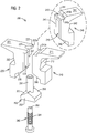
- FIG. 2 illustrates a schematic exploded perspective view of a locking spacer assembly 200 according to an embodiment of the invention.
- the locking spacer assembly 200 may include a first side piece 220, a second side piece 240, a mid piece 260, and a bolt 280.
- the first side piece 220 and the second side piece 240 may have a general C-shape.
- the first side piece 220 may include a top surface 221, an outer surface 222, a bottom surface 226 and an inner surface 227.
- the second side piece 240 may include a top surface 241, an outer surface 242, a bottom surface 246 and an inner surface 247.
- the bolt 280 may be disposed into the mid piece 260 from bottom.
- the mid piece 260 and the bolt 280 may be disposed between the inner surface 227 of the first side piece 220 and the inner surface 247 of the second side piece 240.
- the outer surface 222 of the first side piece 220 and the outer surface 242 of the second side piece 240 may have a profile that is configured to mate with a profile of a first side inner surface 143a of a disk groove 142 and a profile of a second side inner surface 143b of the disk groove 142 such that the outer surface 222 of the first side piece 220 may contact the first side inner surface 143a of the disk groove 142 and the outer surface 242 of the second side piece 240 may contact the second side inner surface 143b of the disk groove 142 after installed into the disk groove 142, as shown in FIGs. 4-9 .
- the first side piece 220 may have a tab 223.
- the tab 223 extends from the top surface 221 and protrudes axially outwardly from the inner surface 227 of the first side piece 220.
- the tab 223 may have a cutout 224.
- the cutout 224 has an opening at an axial end 223a of the tab 223.
- An axial length of the cutout 224 may be equal to or less than an axial length of the tab 223.
- the cutout 224 may be positioned circumferentially at a center of the tab 223.
- the cutout 224 may have a circular shape.
- the first side piece 220 may have a circular groove 225.
- the circular groove 225 is disposed below the tab 223 and extends radially downwardly in the inner surface 227 of the first side piece 220. Radius of the circular groove 225 may be larger than a radius of the cutout 224. Bottom of the circular groove 225 is connected to the bottom surface 226 of the first side piece 220.
- the bottom surface 226 may be a horizontal surface.
- the bottom surface 226 may be a sloped surface. According to an exemplary embodiment shown in FIGs. 2-9 , the bottom surface 226 is a sloped surface.
- the circular groove 225 and the bottom surface 226 of the first side piece 220 are configured to receive the mid piece 260 for easy assembling the locking spacer assembly 200.
- the second side piece 240 may have a recess 243.
- the recess 243 is formed at an edge of the top surface 241 and the inner surface 247 of the second side piece 240.
- the recess 243 may have a general L-shape having a horizontal surface 243a and a vertical surface 243b.
- the recess 243 is configured to receive the tab 223 of the first side piece 220 for easy assembling the locking spacer assembly 200.
- a sloped surface 244 may be disposed from the top surface 241 downwardly to the vertical surface 243b.
- the sloped surface 244 is designed for avoiding flow separation and for improving aerodynamic performance during engine operation.
- the second side piece 240 may have a circular groove 245.
- the circular groove 245 is disposed below the recess 243 and extends radially downwardly in the inner surface 247 of the second side piece 240. Radius of the circular groove 245 of the second side piece 240 may be the same as the radius of the circular groove 225 of the first side piece 220.
- Bottom of the circular groove 245 is connected to the bottom surface 246 of the second side piece 240.
- the bottom surface 246 may be a horizontal surface.
- the bottom surface 246 may be a sloped surface. According to an exemplary embodiment shown in FIGs. 2-9 , the bottom surface 246 is a sloped surface.
- the circular groove 245 and the bottom surface 246 of the second side piece 240 are configured to receive the mid piece 260 for easy assembling the locking spacer assembly 200.
- the mid piece 260 may include a hollow cylindrical body 261 extending in a radial direction.
- the hollow cylindrical body 261 has a threaded inner surface.
- the mid piece 260 may include a base 262.
- the hollow cylindrical body 261 radially penetrates through the base 262 and radially extends upwardly from base 262.
- the hollow cylindrical body 261 may be disposed at a center of the base 262.
- the hollow cylindrical body 261 is configured to be disposed into the circular groove 225 of the first side piece 220 and the circular groove 245 of the second side piece 240 in an assembled state.
- the base 262 has two top surfaces 263 axially extending out from lower end of the hollow cylindrical body 261.
- the base 262 is configured to have a geometric shape such that the two top surfaces 263 of the base 262 align with the bottom surface 226 of the first side piece 220 and the bottom surface 246 of the second side piece 240 respectively.
- the base 262 has a general dovetail shape.
- the top surfaces 263 are tapered upwardly from bottom of the base 262.
- the mid piece 260 is positioned in a radial position such that the mid piece 260 contact the first side piece 220 and the second side piece 260 in the assembled state.
- the mid piece 260 may prevent an axial movement of the first side piece 220 and an axial movement of the second side piece 240 in the assembled state.
- the top surfaces 263 of the mid piece 260 contact the bottom surface 226 of the first side piece 220 and the bottom surface 246 of the second side piece 240 respectively in the assembled state.
- Such arrangement may form an interlock between the mid piece 260 and the first side piece 220 and the second side piece 240 for preventing axial movements of the first side piece 220 and the second side piece 240 in the assemble state.
- a bolt 280 may be disposed into the mid piece 260.
- the bolt 280 may have rolled threads 281. Profile of the threads 281 is designed to increase fatigue strength of the bolt 280.
- the threads 281 of the bolt 280 is engaged with the threaded inner surface of the hollow cylindrical body 261 of the mid piece 260.
- the bolt 280 positions the mid piece 260 in the radial position in the assembled state.
- the bolt 280 may be rotated within the hollow cylindrical body 261 to move the mid piece 260 to the radial position during assembly.
- the bolt 280 may maintain the mid piece 260 in the radial position in the assembled state.
- the bolt 280 may have a recess 282 disposed on top surface of the bolt 280.
- the recess 282 may be engaged with a tool (not shown) for rotating the bolt 280 during assembly.
- FIG. 3 illustrates a schematic assembled perspective view of the locking spacer assembly 200 as shown in FIG. 2 .
- the tab 223 of the first side piece 220 extends axially toward the recess 243 of the second side piece 240 in the assembled state.
- the axial end 223a of the tab 223 may overlap the horizontal surface 243a of the recess 243 in the assembled state for avoiding leakage flow and for aerodynamic stability during engine operation.
- the axial end 223a of the tab 223 may overlap the horizontal surface 243a by 1-2 mm, or by any dimensions for optimum design considerations.
- the bolt 280 is threaded into the mid piece 260.
- the mid piece 260 and the threaded bolt 260 within the mid piece 260 are disposed between the first side piece 220 and the second side piece 240.
- the cutout 224 of the first side piece 220 is designed for an easy tool access to the recess 282 to tight and loose the bolt 280 during assembly.
- the mid piece 260 may be moved to the radial position by rotating the bolt 280 in the hollow cylindrical body 261 of the mid piece 260.
- the mid piece 260 may be lifted to the radial position by rotating the bolt 280 in the hollow cylindrical body 261 to extend out the base 262 of the mid piece 260.
- the top surfaces 263 of the base 262 of the mid piece 260 interlock with the bottom surface 226 of the first side piece 220 and the bottom surface 246 of the second side piece 240 respectively after lifting the mid piece 260 to the radial position. Such arrangement prevents an axial movement of the first side piece 220 and an axial movement of the second side piece 240 during engine operation.
- the hollow cylindrical body 261 of the mid piece 260 is disposed into the circular groove 225 of the first side piece 220 and into the circular groove 245 of the second side piece 240. Height of the hollow cylindrical body 261 is equal to or less than height of the circular groove 225 of the first side piece 220 and height of the circular groove 245 of the second side piece 240 after lifting the mid piece 260.
- the mid piece 260 is lightweight so that only small loads are produced onto the first side piece 220 and the second side piece 240.
- the bolt 280 prevents a radial movement of the mid piece 260.
- the locking spacer assembly 200 has a circumferential width 206 and an axial length 208 after assembly.
- the circumferential width 206 and the axial length 208 correspond to a circumferential width 146 and an axial length 148 of a final spacer slot 144 in a disk groove 142, as shown in FIG. 1 .
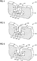
- FIGs. 4-9 illustrate schematic sequential assembly cross section perspective views of a locking spacer assembly 200 according to an embodiment of the invention.
- the bolt 280 is firstly threaded into the mid piece 260.
- the mid piece 260 and the threaded bolt 280 inside the mid piece 260 may then be placed into the final spacer slot 144 and into the disk groove 142 of the rotor disk 140.
- the base 262 of the mid piece 260 rests on a base surface 145 of the disk groove 142.
- the first side piece 220 and the second side piece 240 may then be placed into the disk groove 142 one after another such that the mid piece 260 is disposed between the inner surface 227 of the first side piece 220 and the inner surface 247 of the second side piece 240.
- the second side piece 240 having the recess 243 is placed into the disk groove 142 firstly.
- the first side piece 220 having the tab 223 is placed into the disk groove 142 secondly. It is understood that the first side piece 220 may be placed into the disk groove 142 firstly and the second side piece 240 may be placed into the disk groove 142 secondly.
- the second side piece 240 having the recess 243 may then be placed into the disk groove 142 of the rotor disk 140 between the mid piece 260 and the second side inner surface 143b of the disk groove 142.
- the mid piece 260 may be moved axially toward the first side inner surface 143a to provide adequate axial space for the second side piece 240 to be placed into the disk groove 142.
- the second side piece 240 may then be moved axially toward the second side inner surface 143b such that the outer surface 242 of the second side piece 240 contacts the second side inner surface 143b of the disk groove 142.
- the mid piece 260 may be moved in the same axial direction with the second side piece 240 to provide adequate axial space for the first side piece 220 to be placed into the disk groove 142 in the next step.
- the first side piece 220 having the tab 223 may then be placed into the disk groove 142 between the mid piece 260 and the first side inner surface 143a of the disk groove 142.
- the first side piece 220 may be placed next to the second side piece 240 by overlapping the tab 223 of the first side piece 220 with the recess 243 of the second side piece 240 while placing the first side piece 220 into the disk groove 142 for an easy placement.
- the first side piece 220 may then be moved axially apart from the second side piece 240 toward the first side inner surface 143a such that the outer surface 222 of the first side piece 220 contacts the first side inner surface 143a of the disk groove 142.
- the mid piece 260 may then be moved in an axial direction such that the mid piece 260 aligns with the first side piece 220 and the second side piece 240.
- the mid piece 260 may be placed in a center of the disk groove 142 to align with the first side piece 220 and the second side piece 240.
- the mid piece 260 is then positioned in the radial position in the assembled state by the bolt 280 such that the mid piece 260 contacts the first side piece 220 and the second side piece 240 in the assembled state.
- the mid piece 260 may be lifted from the base surface 145 of the disk groove 142 to the radial position by rotating the bolt 280 radially downwardly.
- the top surfaces 263 of the base 262 of the mid piece 260 interlock with the bottom surface 226 of the first side piece 220 and the bottom surface 246 of the second side piece 240 respectively in the radial position.
- the mid piece 260 prevents axial movements of the first side piece 220 and the second side piece 240 by interlocking interfaces between the mid piece 260 and the first side piece 220 and between the mid piece 260 and the second side piece 240 in the assembled state.
- the bolt 280 maintains the mid piece 260 in the radial position by engaging the threads 281 with the threaded inner surface of the hollow cylindrical body 261 of the mid piece 260 in the assembled state.
- the bolt 280 prevents a radial movement of the mid piece 260 by such an engagement.
- the proposed locking spacer assembly 200 includes a first side piece 220, a second side piece 240 and a mid piece 260 which are interlocked together in the disk groove 142 of the final spacer slot 144 by arrangement and geometric interfaces between the components.
- the proposed locking spacer assembly 200 reduces number of machined surfaces and presents general planar surfaces for easy machining.
- the proposed locking spacer assembly 200 includes a bolt 280 which is threaded into the mid piece 260 to position and maintain a radial position of the mid piece 260.
- the proposed locking spacer assembly 200 eliminates centrifugal loads exerted to the bolt 280 during engine operation.
- the proposed locking spacer assembly 200 significantly reduces component stress and failures and significantly increases component safety margin during engine operation.
Landscapes
- Engineering & Computer Science (AREA)
- Mechanical Engineering (AREA)
- General Engineering & Computer Science (AREA)
- Structures Of Non-Positive Displacement Pumps (AREA)
- Turbine Rotor Nozzle Sealing (AREA)
Description
- This invention relates generally to a locking spacer assembly, in particular, a locking spacer assembly configured to fill a final spacer slot in a disk groove between platforms of adjacent blades of a blade assembly in an industrial gas turbine engine. 2.
- The invention also relates to a corresponding blade assembly, and to a method for installing a locking spacer assembly into a final spacer slot in a disk groove between platforms of adjacent blades of a blade assembly.
- An industrial gas turbine engine typically includes a compressor for compressing air, a combustor for mixing the compressed air with fuel and igniting the mixture, a turbine section for producing mechanical power, and a generator for converting the mechanical power to an electrical power. The compressor and the turbine section include a plurality of blades that are attached on a rotor. The blades are arranged in rows axially spaced apart along the rotor and circumferentially attached to a periphery of a rotor disk.
-
FIG. 1 illustrates a schematic perspective view of a portion of ablade assembly 100. As illustrated inFIG. 1 , theblade assembly 100 includes a plurality ofblades 120 that are attached to arotor disk 140. Eachblade 120 includes aplatform 122 and aroot 124 extending radially inward from theplatform 122. During blade assembly, theblades 120 may be installed to therotor disk 140 by inserting theroots 124 of theblades 120 into adisk groove 142 one at a time. Theblades 120 then may be rotated until theroots 124 of theblade 120 engage thedisk groove 142. Once all of theblades 120 are installed into therotor disk 140, afinal spacer slot 144 is remained in thedisk groove 142 between theplatforms 122 ofadjacent blades 120. Thefinal spacer slot 144 may not be filled with theblade 120 because there is not sufficient space for insertion and rotation. A locking spacer assembly is typically inserted into thefinal spacer slot 144 to lock theblades 120 to therotor disk 140. - Further conventional blade assemblies are described in
GB 659 592 GB 639 320 US2018023402 . A conventional locking spacer assembly typically includes a plurality of pieces, such as side pieces, middle piece, bolt and nut. The conventional locking spacer assembly may experience uncertainties during assembly. For example, the conventional locking spacer assembly may require the bolt to carry a centrifugal load of the locking spacer components. Such arrangement may create undesirable failure mode and small safety margin. Additionally, manufacture cost of the conventional locking spacer assembly may be high due to geometric complexity and numbers of the components of the locking spacer assembly. There is a need to provide a simple, reliable and low cost locking spacer assembly. - Briefly described, aspects of the present invention relate to a locking spacer assembly, in particular, a locking spacer assembly configured to fill a final spacer slot in a disk groove between platforms of adjacent blades of a blade assembly in an industrial gas turbine engine.
- According to an aspect, a locking spacer assembly configured to fill a final spacer slot in a disk groove between platforms of adjacent blades of a blade assembly is presented. The locking spacer assembly comprises a first side piece. The locking spacer assembly comprises a second side piece. The locking spacer assembly comprises a mid piece configured to be disposed between an inner surface of the first side piece and an inner surface of the second side piece. The locking spacer assembly comprises a bolt configured to be disposed into the mid piece. The bolt is configured to position the mid piece in a radial position in an assembled state. The mid piece is configured to contact the first side piece and the second side piece in the assembled state to prevent an axial movement of the first side piece and an axial movement of the second side piece, wherein the mid piece comprises a base and a hollow cylindrical body, wherein the hollow cylindrical body radially penetrates through the base and radially extends upwardly from the base, and wherein the bolt is threaded within the hollow cylindrical body.
- According to an aspect, a blade assembly is presented. The blade assembly comprises a rotor disk comprising a disk groove. The blade assembly comprises a plurality of blades inserted in the disk groove. Each of the blades comprises a platform. A final spacer slot is formed in the disk groove between platforms of adjacent blades. The blade assembly comprises a locking spacer according to the invention.
- According to an aspect, a method for installing a locking spacer assembly into a final spacer slot in a disk groove between platforms of adjacent blades of a blade assembly is presented. The locking spacer assembly comprises a first side piece, a second side piece, a mid piece and a bolt. The method comprises disposing the bolt into the mid piece. The method comprises placing the mid piece and the bolt disposed within the mid piece into the disk groove. The method comprises placing the first side piece and the second side piece into the disk groove one after another such that the mid piece is disposed between an inner surface of the first side piece and an inner surface of the second side piece. The method comprises positioning the mid piece in a radial position in an assembled state by the bolt such that the mid piece contacts the first side piece and the second side piece in the assembled state, wherein the second side piece comprises a recess formed at an edge of a top surface and the inner surface.
- Various aspects and embodiments of the application as described above and hereinafter may not only be used in the combinations explicitly described, but also in other combinations. Modifications will occur to the skilled person upon reading and understanding of the description.
- Exemplary embodiments of the application are explained in further detail with respect to the accompanying drawings. In the drawings.
-
FIG. 1 illustrates a schematic perspective view of a portion of a blade assembly showing a final spacer slot, wherein an embodiment of the inventive locking spacer assembly may be incorporated; -
FIG. 2 illustrates a schematic perspective exploded view of a locking spacer assembly according to an embodiment of the invention; -
FIG. 3 illustrates a schematic perspective assembled perspective view of a locking spacer assembly according to an embodiment of the invention; and -
FIGs. 4-9 illustrate schematic sequential assembly perspective views of a locking spacer assembly according to an embodiment of the invention. - To facilitate understanding, identical reference numerals have been used, where possible, to designate identical elements that are common to the figures.
- A detailed description related to aspects of the present invention is described hereafter with respect to the accompanying figures.
-
FIG. 1 illustrates a schematic perspective view of a portion of ablade assembly 100 showing afinal spacer slot 144 in adisk groove 142 betweenplatforms 122 ofadjacent blades 120. Thefinal spacer slot 144 may have acircumferential width 146 and anaxial length 148. Theblade assembly 100 may be a compressor blade assembly or a turbine blade assembly. Thefinal spacer slot 144 may be filled by inventive embodiments of alocking spacer assembly 200 as shown inFIGs. 2-9 , which are described in more detail below. Thelocking spacer assembly 200 may be installed into thefinal spacer slot 144 in thedisk groove 142 during assembly of theblades 120 to therotor disk 140. Thelocking spacer assembly 200 may be removed from thefinal spacer slot 144 in thedisk groove 142 during disassembly of theblades 120 from therotor disk 140. -
FIG. 2 illustrates a schematic exploded perspective view of alocking spacer assembly 200 according to an embodiment of the invention. With reference toFIG. 2 , thelocking spacer assembly 200 may include afirst side piece 220, asecond side piece 240, amid piece 260, and abolt 280. Thefirst side piece 220 and thesecond side piece 240 may have a general C-shape. Thefirst side piece 220 may include atop surface 221, anouter surface 222, abottom surface 226 and aninner surface 227. Thesecond side piece 240 may include atop surface 241, anouter surface 242, abottom surface 246 and aninner surface 247. Thebolt 280 may be disposed into themid piece 260 from bottom. Themid piece 260 and thebolt 280 may be disposed between theinner surface 227 of thefirst side piece 220 and theinner surface 247 of thesecond side piece 240. Theouter surface 222 of thefirst side piece 220 and theouter surface 242 of thesecond side piece 240 may have a profile that is configured to mate with a profile of a first sideinner surface 143a of adisk groove 142 and a profile of a second sideinner surface 143b of thedisk groove 142 such that theouter surface 222 of thefirst side piece 220 may contact the first sideinner surface 143a of thedisk groove 142 and theouter surface 242 of thesecond side piece 240 may contact the second sideinner surface 143b of thedisk groove 142 after installed into thedisk groove 142, as shown inFIGs. 4-9 . - The
first side piece 220 may have atab 223. Thetab 223 extends from thetop surface 221 and protrudes axially outwardly from theinner surface 227 of thefirst side piece 220. Thetab 223 may have acutout 224. Thecutout 224 has an opening at anaxial end 223a of thetab 223. An axial length of thecutout 224 may be equal to or less than an axial length of thetab 223. Thecutout 224 may be positioned circumferentially at a center of thetab 223. Thecutout 224 may have a circular shape. Thefirst side piece 220 may have acircular groove 225. Thecircular groove 225 is disposed below thetab 223 and extends radially downwardly in theinner surface 227 of thefirst side piece 220. Radius of thecircular groove 225 may be larger than a radius of thecutout 224. Bottom of thecircular groove 225 is connected to thebottom surface 226 of thefirst side piece 220. Thebottom surface 226 may be a horizontal surface. Thebottom surface 226 may be a sloped surface. According to an exemplary embodiment shown inFIGs. 2-9 , thebottom surface 226 is a sloped surface. Thecircular groove 225 and thebottom surface 226 of thefirst side piece 220 are configured to receive themid piece 260 for easy assembling the lockingspacer assembly 200. - For illustration purpose, a different perspective view of the
second side piece 240 is also shown inFIG. 2 . With reference toFIG. 2 , thesecond side piece 240 may have arecess 243. Therecess 243 is formed at an edge of thetop surface 241 and theinner surface 247 of thesecond side piece 240. Therecess 243 may have a general L-shape having ahorizontal surface 243a and avertical surface 243b. Therecess 243 is configured to receive thetab 223 of thefirst side piece 220 for easy assembling the lockingspacer assembly 200. Asloped surface 244 may be disposed from thetop surface 241 downwardly to thevertical surface 243b. Thesloped surface 244 is designed for avoiding flow separation and for improving aerodynamic performance during engine operation. Thesecond side piece 240 may have acircular groove 245. Thecircular groove 245 is disposed below therecess 243 and extends radially downwardly in theinner surface 247 of thesecond side piece 240. Radius of thecircular groove 245 of thesecond side piece 240 may be the same as the radius of thecircular groove 225 of thefirst side piece 220. Bottom of thecircular groove 245 is connected to thebottom surface 246 of thesecond side piece 240. Thebottom surface 246 may be a horizontal surface. Thebottom surface 246 may be a sloped surface. According to an exemplary embodiment shown inFIGs. 2-9 , thebottom surface 246 is a sloped surface. Thecircular groove 245 and thebottom surface 246 of thesecond side piece 240 are configured to receive themid piece 260 for easy assembling the lockingspacer assembly 200. - The
mid piece 260 may include a hollowcylindrical body 261 extending in a radial direction. The hollowcylindrical body 261 has a threaded inner surface. Themid piece 260 may include abase 262. The hollowcylindrical body 261 radially penetrates through thebase 262 and radially extends upwardly frombase 262. The hollowcylindrical body 261 may be disposed at a center of thebase 262. The hollowcylindrical body 261 is configured to be disposed into thecircular groove 225 of thefirst side piece 220 and thecircular groove 245 of thesecond side piece 240 in an assembled state. Thebase 262 has twotop surfaces 263 axially extending out from lower end of the hollowcylindrical body 261. Thebase 262 is configured to have a geometric shape such that the twotop surfaces 263 of the base 262 align with thebottom surface 226 of thefirst side piece 220 and thebottom surface 246 of thesecond side piece 240 respectively. According to an exemplary embodiment shown inFIGs. 2-9 , thebase 262 has a general dovetail shape. The top surfaces 263 are tapered upwardly from bottom of thebase 262. During assemble, themid piece 260 is positioned in a radial position such that themid piece 260 contact thefirst side piece 220 and thesecond side piece 260 in the assembled state. Themid piece 260 may prevent an axial movement of thefirst side piece 220 and an axial movement of thesecond side piece 240 in the assembled state. Particularly, thetop surfaces 263 of themid piece 260 contact thebottom surface 226 of thefirst side piece 220 and thebottom surface 246 of thesecond side piece 240 respectively in the assembled state. Such arrangement may form an interlock between themid piece 260 and thefirst side piece 220 and thesecond side piece 240 for preventing axial movements of thefirst side piece 220 and thesecond side piece 240 in the assemble state. - A
bolt 280 may be disposed into themid piece 260. Thebolt 280 may have rolledthreads 281. Profile of thethreads 281 is designed to increase fatigue strength of thebolt 280. Thethreads 281 of thebolt 280 is engaged with the threaded inner surface of the hollowcylindrical body 261 of themid piece 260. Thebolt 280 positions themid piece 260 in the radial position in the assembled state. Thebolt 280 may be rotated within the hollowcylindrical body 261 to move themid piece 260 to the radial position during assembly. Thebolt 280 may maintain themid piece 260 in the radial position in the assembled state. Thebolt 280 may have arecess 282 disposed on top surface of thebolt 280. Therecess 282 may be engaged with a tool (not shown) for rotating thebolt 280 during assembly. -
FIG. 3 illustrates a schematic assembled perspective view of the lockingspacer assembly 200 as shown inFIG. 2 . With reference toFIG. 3 , thetab 223 of thefirst side piece 220 extends axially toward therecess 243 of thesecond side piece 240 in the assembled state. Theaxial end 223a of thetab 223 may overlap thehorizontal surface 243a of therecess 243 in the assembled state for avoiding leakage flow and for aerodynamic stability during engine operation. For example, theaxial end 223a of thetab 223 may overlap thehorizontal surface 243a by 1-2 mm, or by any dimensions for optimum design considerations. Thebolt 280 is threaded into themid piece 260. Themid piece 260 and the threadedbolt 260 within themid piece 260 are disposed between thefirst side piece 220 and thesecond side piece 240. Thecutout 224 of thefirst side piece 220 is designed for an easy tool access to therecess 282 to tight and loose thebolt 280 during assembly. Themid piece 260 may be moved to the radial position by rotating thebolt 280 in the hollowcylindrical body 261 of themid piece 260. According to an exemplary embodiment shown inFIG. 3 , themid piece 260 may be lifted to the radial position by rotating thebolt 280 in the hollowcylindrical body 261 to extend out thebase 262 of themid piece 260. The top surfaces 263 of thebase 262 of themid piece 260 interlock with thebottom surface 226 of thefirst side piece 220 and thebottom surface 246 of thesecond side piece 240 respectively after lifting themid piece 260 to the radial position. Such arrangement prevents an axial movement of thefirst side piece 220 and an axial movement of thesecond side piece 240 during engine operation. The hollowcylindrical body 261 of themid piece 260 is disposed into thecircular groove 225 of thefirst side piece 220 and into thecircular groove 245 of thesecond side piece 240. Height of the hollowcylindrical body 261 is equal to or less than height of thecircular groove 225 of thefirst side piece 220 and height of thecircular groove 245 of thesecond side piece 240 after lifting themid piece 260. Themid piece 260 is lightweight so that only small loads are produced onto thefirst side piece 220 and thesecond side piece 240. Thebolt 280 prevents a radial movement of themid piece 260. The lockingspacer assembly 200 has acircumferential width 206 and anaxial length 208 after assembly. Thecircumferential width 206 and theaxial length 208 correspond to acircumferential width 146 and anaxial length 148 of afinal spacer slot 144 in adisk groove 142, as shown inFIG. 1 . -
FIGs. 4-9 illustrate schematic sequential assembly cross section perspective views of a lockingspacer assembly 200 according to an embodiment of the invention. With reference toFIG. 4 , thebolt 280 is firstly threaded into themid piece 260. Themid piece 260 and the threadedbolt 280 inside themid piece 260 may then be placed into thefinal spacer slot 144 and into thedisk groove 142 of therotor disk 140. Thebase 262 of themid piece 260 rests on abase surface 145 of thedisk groove 142. Thefirst side piece 220 and thesecond side piece 240 may then be placed into thedisk groove 142 one after another such that themid piece 260 is disposed between theinner surface 227 of thefirst side piece 220 and theinner surface 247 of thesecond side piece 240. According to an exemplary embodiment shown inFIGs. 4-9 , thesecond side piece 240 having therecess 243 is placed into thedisk groove 142 firstly. Thefirst side piece 220 having thetab 223 is placed into thedisk groove 142 secondly. It is understood that thefirst side piece 220 may be placed into thedisk groove 142 firstly and thesecond side piece 240 may be placed into thedisk groove 142 secondly. - With reference to
FIG. 5 , thesecond side piece 240 having therecess 243 may then be placed into thedisk groove 142 of therotor disk 140 between themid piece 260 and the second sideinner surface 143b of thedisk groove 142. Themid piece 260 may be moved axially toward the first sideinner surface 143a to provide adequate axial space for thesecond side piece 240 to be placed into thedisk groove 142. - With reference to
FIG. 6 , thesecond side piece 240 may then be moved axially toward the second sideinner surface 143b such that theouter surface 242 of thesecond side piece 240 contacts the second sideinner surface 143b of thedisk groove 142. Themid piece 260 may be moved in the same axial direction with thesecond side piece 240 to provide adequate axial space for thefirst side piece 220 to be placed into thedisk groove 142 in the next step. - With reference to
FIG. 7 , thefirst side piece 220 having thetab 223 may then be placed into thedisk groove 142 between themid piece 260 and the first sideinner surface 143a of thedisk groove 142. Thefirst side piece 220 may be placed next to thesecond side piece 240 by overlapping thetab 223 of thefirst side piece 220 with therecess 243 of thesecond side piece 240 while placing thefirst side piece 220 into thedisk groove 142 for an easy placement. - With reference to
FIG. 8 , thefirst side piece 220 may then be moved axially apart from thesecond side piece 240 toward the first sideinner surface 143a such that theouter surface 222 of thefirst side piece 220 contacts the first sideinner surface 143a of thedisk groove 142. Themid piece 260 may then be moved in an axial direction such that themid piece 260 aligns with thefirst side piece 220 and thesecond side piece 240. Themid piece 260 may be placed in a center of thedisk groove 142 to align with thefirst side piece 220 and thesecond side piece 240. - With reference to
FIG. 9 , themid piece 260 is then positioned in the radial position in the assembled state by thebolt 280 such that themid piece 260 contacts thefirst side piece 220 and thesecond side piece 240 in the assembled state. According to an exemplary embodiment shown inFIG. 9 , themid piece 260 may be lifted from thebase surface 145 of thedisk groove 142 to the radial position by rotating thebolt 280 radially downwardly. The top surfaces 263 of thebase 262 of themid piece 260 interlock with thebottom surface 226 of thefirst side piece 220 and thebottom surface 246 of thesecond side piece 240 respectively in the radial position. Themid piece 260 prevents axial movements of thefirst side piece 220 and thesecond side piece 240 by interlocking interfaces between themid piece 260 and thefirst side piece 220 and between themid piece 260 and thesecond side piece 240 in the assembled state. Thebolt 280 maintains themid piece 260 in the radial position by engaging thethreads 281 with the threaded inner surface of the hollowcylindrical body 261 of themid piece 260 in the assembled state. Thebolt 280 prevents a radial movement of themid piece 260 by such an engagement. - According to an aspect, the proposed
locking spacer assembly 200 includes afirst side piece 220, asecond side piece 240 and amid piece 260 which are interlocked together in thedisk groove 142 of thefinal spacer slot 144 by arrangement and geometric interfaces between the components. The proposedlocking spacer assembly 200 reduces number of machined surfaces and presents general planar surfaces for easy machining. The proposedlocking spacer assembly 200 includes abolt 280 which is threaded into themid piece 260 to position and maintain a radial position of themid piece 260. The proposedlocking spacer assembly 200 eliminates centrifugal loads exerted to thebolt 280 during engine operation. The proposedlocking spacer assembly 200 significantly reduces component stress and failures and significantly increases component safety margin during engine operation. - Although various embodiments that incorporate the teachings of the present invention have been shown and described in detail herein, those skilled in the art can readily devise many other varied embodiments within the scope of the claims that still incorporate these teachings. The invention is not limited in its application to the exemplary embodiment details of construction and the arrangement of components set forth in the description or illustrated in the drawings. The invention is capable of other embodiments and of being practiced or of being carried out in various ways within the scope of the claims. Also, it is to be understood that the phraseology and terminology used herein is for the purpose of description and should not be regarded as limiting. The use of "including," "comprising," or "having" and variations thereof herein is meant to encompass the items listed thereafter and equivalents thereof as well as additional items. Unless specified or limited otherwise, the terms "mounted," "connected," "supported," and "coupled" and variations thereof are used broadly and encompass direct and indirect mountings, connections, supports, and couplings. Further, "connected" and "coupled" are not restricted to physical or mechanical connections or couplings.
-
- 100:
- Blade Assembly
- 120:
- Blade
- 122:
- Platform of Blade
- 124:
- Root of Blade
- 140:
- Rotor Disk
- 142:
- Disk Groove
- 143a:
- First Side Inner Surface of Disk Groove
- 143b:
- Second Side Inner Surface of Disk Groove
- 144:
- Final Spacer Slot
- 145:
- Base Surface of Disk Groove
- 146:
- Circumferential Width of Final Spacer Slot
- 148:
- Axial Length of Final Spacer Slot
- 200:
- Locking Spacer Assembly
- 206:
- Circumferential Width of Locking Spacer Assembly
- 208:
- Axial Length of Locking Spacer Assembly
- 220:
- First Side Piece
- 221:
- Top Surface of the First Side Piece
- 222:
- Outer Surface of the First Side Piece
- 223:
- Tab of the First Side Piece
- 223a:
- Axial End of Tab
- 224:
- Cutout of Tab of First Side Piece
- 225:
- Circular Groove of First Side Piece
- 226:
- Bottom Surface of Frist Side Piece
- 227:
- Inner Surface of First Side Piece
- 240:
- Second Side Piece
- 241:
- Top Surface of the Second Side Piece
- 242:
- Outer Surface of the Second Side Piece
- 243:
- Recess of the Second Side Piece
- 243a:
- Horizontal Surface of Recess
- 243b:
- Vertical Surface of Recess
- 244:
- Slope Surface of Second Side Piece
- 245:
- Circular Groove of Second Side Piece
- 246:
- Bottom Surface of Second Side Piece
- 247:
- Inner Surface of Second Side Piece
- 260:
- Mid Piece
- 261:
- Hollow Cylindrical Body of Mid Piece
- 262:
- Base of Mid Piece
- 263:
- Top Surface of Base of Mid Piece
- 280:
- Bolt
- 281:
- Threads of Bolt
- 282:
- Recess of Bolt
Claims (12)
- A locking spacer assembly (200) configured to fill a final spacer slot (144) in a disk groove (142) between platforms (122) of adjacent blades (120) of a blade assembly (100) comprising:a first side piece (220);a second side piece (240);a mid piece (260) configured to be disposed between an inner surface (227) of the first side piece (220) and an inner surface (247) of the second side piece (240); anda bolt (280) configured to be disposed into the mid piece (260),wherein the bolt (280) is configured to position the mid piece (260) in a radial position in an assembled state,wherein the mid piece (260) is configured to contact the first side piece (220) and the second side piece (240) in the assembled state to prevent an axial movement of the first side piece (220) and an axial movement of the second side piece (240),wherein the mid piece (260) comprises a base (262) and a hollow cylindrical body (261),wherein the hollow cylindrical body (261) radially penetrates through the base (262) and radially extends upwardly from the base (262), andwherein the bolt (280) is threaded within the hollow cylindrical body (261).
- The locking spacer assembly (200) as claimed in claim 1,wherein the base (262) comprises two top surfaces (263) axially extending out from a lower end of the hollow cylindrical body (261), andwherein the two top surfaces (263) contact a bottom surface (226) of the first side piece (220) and a bottom surface (246) of the second side piece (240) in the assembled state.
- The locking spacer assembly (200) as claimed in claim 1,wherein the first side piece (220) comprises a circular groove (225) extending radially downwardly in the inner surface (227),wherein the second side piece (240) comprises a circular groove (245) extending radially downwardly in the inner surface (247), andwherein the hollow cylindrical body (261) of the mid piece (260) is disposed into the circular groove (225) of the first side piece (220) and the circular groove (245) of the second side piece (240) in the assembled state.
- The locking spacer assembly (200) as claimed in claim 1, wherein the base (262) comprises a dovetail shape.
- The locking spacer assembly (200) as claimed in claim 1, wherein the first side piece (220) comprises a tab (223) extending from a top surface (221) and protruding axially outwardly from the inner surface (227).
- The locking spacer assembly (200) as claimed in claim 5, wherein the tab (223) comprises a cutout (224).
- The locking spacer assembly (200) as claimed in claim 1, wherein the second side piece (240) comprises a recess (243) formed at an edge of a top surface (241) and the inner surface (247).
- A blade assembly (100) comprising:a rotor disk comprising a disk groove (142);a plurality of blades (120) inserted in the disk groove (142), wherein each of the blades (120) comprises a platform, and wherein a final spacer slot (144) is formed in the disk groove (142) between platforms (122) of adjacent blades (120); anda locking spacer assembly (200) as claimed in any of claims 1-7, the locking spacer assembly (200) configured to fill the final spacer slot (144).
- A method for installing a locking spacer assembly (200) into a final spacer slot (144) in a disk groove (142) between platforms (122) of adjacent blades (120) of a blade assembly (100), wherein the locking spacer assembly (200) comprises a first side piece (220), a second side piece (240), a mid piece (260) and a bolt (280), the method comprising:disposing the bolt (280) into the mid piece (260);placing the mid piece (260) and the bolt (280) disposed within the mid piece (260) into the disk groove (142);placing the first side piece (220) and the second side piece (240) into the disk groove (142) one after another such that the mid piece (260) is disposed between an inner surface (227) of the first side piece (220) and an inner surface (247) of the second side piece (240); andpositioning the mid piece (260) in a radial position in an assembled state by the bolt (280) such that the mid piece (260) contacts the first side piece (220) and the second side piece (240) in the assembled state,wherein the second side piece (240) comprises a recess (243) formed at an edge of a top surface (241) and the inner surface (247).
- The method as claimed in claim 9, further comprising axially moving the mid piece (260) in the disk groove (142) for aligning the mid piece (260) with the first side piece (220) and the second side piece (240) prior to positioning the mid piece (260) in the radial position.
- The method as claimed in claim 9, wherein the first side piece (220) comprises a tab (223) extending from a top surface (221) and protruding axially outwardly from the inner surface (227).
- The method as claimed in claim 11, further comprising placing the first side piece (220) and the second side piece (240) into the disk groove (142) by overlapping the tab (223) with the recess (243).
Applications Claiming Priority (1)
| Application Number | Priority Date | Filing Date | Title |
|---|---|---|---|
| PCT/US2018/028141 WO2019203819A1 (en) | 2018-04-18 | 2018-04-18 | Locking spacer assembly, corresponding blade assembly, method for installing a locking spacer |
Publications (2)
| Publication Number | Publication Date |
|---|---|
| EP3765715A1 EP3765715A1 (en) | 2021-01-20 |
| EP3765715B1 true EP3765715B1 (en) | 2021-12-29 |
Family
ID=62116986
Family Applications (1)
| Application Number | Title | Priority Date | Filing Date |
|---|---|---|---|
| EP18723138.6A Active EP3765715B1 (en) | 2018-04-18 | 2018-04-18 | Locking spacer assembly, blade assembly and method for installing a locking spacer |
Country Status (4)
| Country | Link |
|---|---|
| US (1) | US11319821B2 (en) |
| EP (1) | EP3765715B1 (en) |
| CN (1) | CN111954751B (en) |
| WO (1) | WO2019203819A1 (en) |
Families Citing this family (2)
| Publication number | Priority date | Publication date | Assignee | Title |
|---|---|---|---|---|
| JP7551444B2 (en) * | 2020-10-15 | 2024-09-17 | キヤノン株式会社 | Zoom lens and imaging device |
| EP4479630A2 (en) * | 2022-04-08 | 2024-12-25 | Siemens Energy Global GmbH & Co. KG | Locking spacer assemblies and method for installing a locking spacer assembly |
Family Cites Families (15)
| Publication number | Priority date | Publication date | Assignee | Title |
|---|---|---|---|---|
| US2421855A (en) * | 1943-07-23 | 1947-06-10 | United Aircraft Corp | Turbine blade locking device |
| NL75780C (en) * | 1948-09-17 | |||
| GB639320A (en) * | 1948-10-22 | 1950-06-28 | Frank Rosslyn Harris | Improvements in or relating to the mounting of turbine, compressor or like blades |
| US3721506A (en) * | 1971-05-25 | 1973-03-20 | Gen Electric | Split-nut blade locking assembly |
| DE10134611A1 (en) | 2000-12-16 | 2002-06-27 | Alstom Switzerland Ltd | Fixing device for a blade mounting of a compressor or turbine stage of a gas turbine system comprises a blade having a counter-contour corresponding to a connecting element of a wedge element to produce a form-locking connection |
| DE10310432A1 (en) * | 2003-03-11 | 2004-09-23 | Alstom Technology Ltd | Rotor end |
| DE10346239A1 (en) * | 2003-10-06 | 2005-04-21 | Alstom Technology Ltd Baden | Method for fixing the blading of a turbomachine and fixing device |
| US7435055B2 (en) * | 2005-03-29 | 2008-10-14 | Siemens Power Generation, Inc. | Locking spacer assembly for a turbine engine |
| EP1803899A1 (en) * | 2006-01-02 | 2007-07-04 | Siemens Aktiengesellschaft | Blade locking assembly for a turbomachine |
| US8523529B2 (en) * | 2009-11-11 | 2013-09-03 | General Electric Company | Locking spacer assembly for a circumferential entry airfoil attachment system |
| US9512732B2 (en) * | 2013-10-16 | 2016-12-06 | General Electric Company | Locking spacer assembly inserted between rotor blades |
| US9341071B2 (en) * | 2013-10-16 | 2016-05-17 | General Electric Company | Locking spacer assembly |
| US9464531B2 (en) * | 2013-10-16 | 2016-10-11 | General Electric Company | Locking spacer assembly |
| EP3054098A1 (en) * | 2015-02-05 | 2016-08-10 | Siemens Aktiengesellschaft | Closure assembly for closing a blade ring on a blade holder of a turbo engine |
| US10519970B2 (en) * | 2017-02-09 | 2019-12-31 | DOOSAN Heavy Industries Construction Co., LTD | Compressor blade locking mechanism in disk with tangential groove |
-
2018
- 2018-04-18 EP EP18723138.6A patent/EP3765715B1/en active Active
- 2018-04-18 US US17/040,280 patent/US11319821B2/en active Active
- 2018-04-18 WO PCT/US2018/028141 patent/WO2019203819A1/en not_active Ceased
- 2018-04-18 CN CN201880092499.XA patent/CN111954751B/en active Active
Also Published As
| Publication number | Publication date |
|---|---|
| EP3765715A1 (en) | 2021-01-20 |
| CN111954751B (en) | 2022-06-21 |
| CN111954751A (en) | 2020-11-17 |
| US11319821B2 (en) | 2022-05-03 |
| US20210003022A1 (en) | 2021-01-07 |
| WO2019203819A1 (en) | 2019-10-24 |
Similar Documents
| Publication | Publication Date | Title |
|---|---|---|
| EP1744013B1 (en) | Method for loading and tangential locking of rotor blades and corresponding rotor blade | |
| US9512732B2 (en) | Locking spacer assembly inserted between rotor blades | |
| US7618234B2 (en) | Hook ring segment for a compressor vane | |
| EP2812541B1 (en) | Turbine engine shaft coupling | |
| EP2586988B1 (en) | Turbine cover plate assembly | |
| KR102170572B1 (en) | Turbomachine rotor assembly and method | |
| US20160298642A1 (en) | Fan, in particular for a turbine engine | |
| US11319821B2 (en) | Locking spacer assembly, corresponding blade assembly, method for installing a locking spacer | |
| US7708529B2 (en) | Rotor of a turbo engine, e.g., a gas turbine rotor | |
| US8277190B2 (en) | Turbomachine rotor assembly and method | |
| US8545184B2 (en) | Locking spacer assembly | |
| EP2299059B1 (en) | An aerofoil blade assembly | |
| EP3409898B1 (en) | Belly band seals and method | |
| WO2014105682A1 (en) | Turbine exhaust case multi-piece frame | |
| US11359501B2 (en) | Locking spacer assembly, corresponding blade assembly, method for installing a locking spacer | |
| US10570756B2 (en) | Closing assembly for closing a blade ring, associated blade supports, turbomachine, and method for inserting a closing assembly | |
| US20190063237A1 (en) | Locking spacer assembly | |
| US8757981B2 (en) | Locking spacer assembly for a turbine engine | |
| EP2642136A1 (en) | Coupling structure and method to connect coupling parts | |
| EP2339121A2 (en) | Non-circular closure pins for a turbine bucket assembly | |
| CN206626020U (en) | Stationary blade segment and axial fluid machine with the same | |
| EP3303773B1 (en) | Attachment system for a turbine airfoil usable in a gas turbine engine | |
| US9816380B2 (en) | Turbine rotor for a thermoelectric power station |
Legal Events
| Date | Code | Title | Description |
|---|---|---|---|
| STAA | Information on the status of an ep patent application or granted ep patent |
Free format text: STATUS: UNKNOWN |
|
| STAA | Information on the status of an ep patent application or granted ep patent |
Free format text: STATUS: THE INTERNATIONAL PUBLICATION HAS BEEN MADE |
|
| PUAI | Public reference made under article 153(3) epc to a published international application that has entered the european phase |
Free format text: ORIGINAL CODE: 0009012 |
|
| STAA | Information on the status of an ep patent application or granted ep patent |
Free format text: STATUS: REQUEST FOR EXAMINATION WAS MADE |
|
| 17P | Request for examination filed |
Effective date: 20201001 |
|
| AK | Designated contracting states |
Kind code of ref document: A1 Designated state(s): AL AT BE BG CH CY CZ DE DK EE ES FI FR GB GR HR HU IE IS IT LI LT LU LV MC MK MT NL NO PL PT RO RS SE SI SK SM TR |
|
| AX | Request for extension of the european patent |
Extension state: BA ME |
|
| RAP1 | Party data changed (applicant data changed or rights of an application transferred) |
Owner name: SIEMENS ENERGY GLOBAL GMBH & CO. KG |
|
| DAV | Request for validation of the european patent (deleted) | ||
| DAX | Request for extension of the european patent (deleted) | ||
| GRAP | Despatch of communication of intention to grant a patent |
Free format text: ORIGINAL CODE: EPIDOSNIGR1 |
|
| STAA | Information on the status of an ep patent application or granted ep patent |
Free format text: STATUS: GRANT OF PATENT IS INTENDED |
|
| INTG | Intention to grant announced |
Effective date: 20210909 |
|
| GRAS | Grant fee paid |
Free format text: ORIGINAL CODE: EPIDOSNIGR3 |
|
| GRAA | (expected) grant |
Free format text: ORIGINAL CODE: 0009210 |
|
| STAA | Information on the status of an ep patent application or granted ep patent |
Free format text: STATUS: THE PATENT HAS BEEN GRANTED |
|
| AK | Designated contracting states |
Kind code of ref document: B1 Designated state(s): AL AT BE BG CH CY CZ DE DK EE ES FI FR GB GR HR HU IE IS IT LI LT LU LV MC MK MT NL NO PL PT RO RS SE SI SK SM TR |
|
| REG | Reference to a national code |
Ref country code: GB Ref legal event code: FG4D |
|
| REG | Reference to a national code |
Ref country code: CH Ref legal event code: EP |
|
| REG | Reference to a national code |
Ref country code: AT Ref legal event code: REF Ref document number: 1458813 Country of ref document: AT Kind code of ref document: T Effective date: 20220115 |
|
| REG | Reference to a national code |
Ref country code: IE Ref legal event code: FG4D |
|
| REG | Reference to a national code |
Ref country code: DE Ref legal event code: R096 Ref document number: 602018028782 Country of ref document: DE |
|
| REG | Reference to a national code |
Ref country code: LT Ref legal event code: MG9D |
|
| PG25 | Lapsed in a contracting state [announced via postgrant information from national office to epo] |
Ref country code: RS Free format text: LAPSE BECAUSE OF FAILURE TO SUBMIT A TRANSLATION OF THE DESCRIPTION OR TO PAY THE FEE WITHIN THE PRESCRIBED TIME-LIMIT Effective date: 20211229 Ref country code: LT Free format text: LAPSE BECAUSE OF FAILURE TO SUBMIT A TRANSLATION OF THE DESCRIPTION OR TO PAY THE FEE WITHIN THE PRESCRIBED TIME-LIMIT Effective date: 20211229 Ref country code: FI Free format text: LAPSE BECAUSE OF FAILURE TO SUBMIT A TRANSLATION OF THE DESCRIPTION OR TO PAY THE FEE WITHIN THE PRESCRIBED TIME-LIMIT Effective date: 20211229 Ref country code: BG Free format text: LAPSE BECAUSE OF FAILURE TO SUBMIT A TRANSLATION OF THE DESCRIPTION OR TO PAY THE FEE WITHIN THE PRESCRIBED TIME-LIMIT Effective date: 20220329 |
|
| REG | Reference to a national code |
Ref country code: NL Ref legal event code: MP Effective date: 20211229 |
|
| REG | Reference to a national code |
Ref country code: AT Ref legal event code: MK05 Ref document number: 1458813 Country of ref document: AT Kind code of ref document: T Effective date: 20211229 |
|
| PG25 | Lapsed in a contracting state [announced via postgrant information from national office to epo] |
Ref country code: SE Free format text: LAPSE BECAUSE OF FAILURE TO SUBMIT A TRANSLATION OF THE DESCRIPTION OR TO PAY THE FEE WITHIN THE PRESCRIBED TIME-LIMIT Effective date: 20211229 Ref country code: NO Free format text: LAPSE BECAUSE OF FAILURE TO SUBMIT A TRANSLATION OF THE DESCRIPTION OR TO PAY THE FEE WITHIN THE PRESCRIBED TIME-LIMIT Effective date: 20220329 Ref country code: LV Free format text: LAPSE BECAUSE OF FAILURE TO SUBMIT A TRANSLATION OF THE DESCRIPTION OR TO PAY THE FEE WITHIN THE PRESCRIBED TIME-LIMIT Effective date: 20211229 Ref country code: HR Free format text: LAPSE BECAUSE OF FAILURE TO SUBMIT A TRANSLATION OF THE DESCRIPTION OR TO PAY THE FEE WITHIN THE PRESCRIBED TIME-LIMIT Effective date: 20211229 Ref country code: GR Free format text: LAPSE BECAUSE OF FAILURE TO SUBMIT A TRANSLATION OF THE DESCRIPTION OR TO PAY THE FEE WITHIN THE PRESCRIBED TIME-LIMIT Effective date: 20220330 |
|
| PG25 | Lapsed in a contracting state [announced via postgrant information from national office to epo] |
Ref country code: NL Free format text: LAPSE BECAUSE OF FAILURE TO SUBMIT A TRANSLATION OF THE DESCRIPTION OR TO PAY THE FEE WITHIN THE PRESCRIBED TIME-LIMIT Effective date: 20211229 |
|
| PG25 | Lapsed in a contracting state [announced via postgrant information from national office to epo] |
Ref country code: SM Free format text: LAPSE BECAUSE OF FAILURE TO SUBMIT A TRANSLATION OF THE DESCRIPTION OR TO PAY THE FEE WITHIN THE PRESCRIBED TIME-LIMIT Effective date: 20211229 Ref country code: SK Free format text: LAPSE BECAUSE OF FAILURE TO SUBMIT A TRANSLATION OF THE DESCRIPTION OR TO PAY THE FEE WITHIN THE PRESCRIBED TIME-LIMIT Effective date: 20211229 Ref country code: RO Free format text: LAPSE BECAUSE OF FAILURE TO SUBMIT A TRANSLATION OF THE DESCRIPTION OR TO PAY THE FEE WITHIN THE PRESCRIBED TIME-LIMIT Effective date: 20211229 Ref country code: PT Free format text: LAPSE BECAUSE OF FAILURE TO SUBMIT A TRANSLATION OF THE DESCRIPTION OR TO PAY THE FEE WITHIN THE PRESCRIBED TIME-LIMIT Effective date: 20220429 Ref country code: ES Free format text: LAPSE BECAUSE OF FAILURE TO SUBMIT A TRANSLATION OF THE DESCRIPTION OR TO PAY THE FEE WITHIN THE PRESCRIBED TIME-LIMIT Effective date: 20211229 Ref country code: EE Free format text: LAPSE BECAUSE OF FAILURE TO SUBMIT A TRANSLATION OF THE DESCRIPTION OR TO PAY THE FEE WITHIN THE PRESCRIBED TIME-LIMIT Effective date: 20211229 Ref country code: CZ Free format text: LAPSE BECAUSE OF FAILURE TO SUBMIT A TRANSLATION OF THE DESCRIPTION OR TO PAY THE FEE WITHIN THE PRESCRIBED TIME-LIMIT Effective date: 20211229 |
|
| PG25 | Lapsed in a contracting state [announced via postgrant information from national office to epo] |
Ref country code: PL Free format text: LAPSE BECAUSE OF FAILURE TO SUBMIT A TRANSLATION OF THE DESCRIPTION OR TO PAY THE FEE WITHIN THE PRESCRIBED TIME-LIMIT Effective date: 20211229 Ref country code: AT Free format text: LAPSE BECAUSE OF FAILURE TO SUBMIT A TRANSLATION OF THE DESCRIPTION OR TO PAY THE FEE WITHIN THE PRESCRIBED TIME-LIMIT Effective date: 20211229 |
|
| PG25 | Lapsed in a contracting state [announced via postgrant information from national office to epo] |
Ref country code: IS Free format text: LAPSE BECAUSE OF FAILURE TO SUBMIT A TRANSLATION OF THE DESCRIPTION OR TO PAY THE FEE WITHIN THE PRESCRIBED TIME-LIMIT Effective date: 20220429 |
|
| REG | Reference to a national code |
Ref country code: DE Ref legal event code: R097 Ref document number: 602018028782 Country of ref document: DE |
|
| PG25 | Lapsed in a contracting state [announced via postgrant information from national office to epo] |
Ref country code: DK Free format text: LAPSE BECAUSE OF FAILURE TO SUBMIT A TRANSLATION OF THE DESCRIPTION OR TO PAY THE FEE WITHIN THE PRESCRIBED TIME-LIMIT Effective date: 20211229 Ref country code: AL Free format text: LAPSE BECAUSE OF FAILURE TO SUBMIT A TRANSLATION OF THE DESCRIPTION OR TO PAY THE FEE WITHIN THE PRESCRIBED TIME-LIMIT Effective date: 20211229 |
|
| PLBE | No opposition filed within time limit |
Free format text: ORIGINAL CODE: 0009261 |
|
| STAA | Information on the status of an ep patent application or granted ep patent |
Free format text: STATUS: NO OPPOSITION FILED WITHIN TIME LIMIT |
|
| 26N | No opposition filed |
Effective date: 20220930 |
|
| REG | Reference to a national code |
Ref country code: BE Ref legal event code: MM Effective date: 20220430 |
|
| PG25 | Lapsed in a contracting state [announced via postgrant information from national office to epo] |
Ref country code: MC Free format text: LAPSE BECAUSE OF FAILURE TO SUBMIT A TRANSLATION OF THE DESCRIPTION OR TO PAY THE FEE WITHIN THE PRESCRIBED TIME-LIMIT Effective date: 20211229 Ref country code: LU Free format text: LAPSE BECAUSE OF NON-PAYMENT OF DUE FEES Effective date: 20220418 |
|
| PG25 | Lapsed in a contracting state [announced via postgrant information from national office to epo] |
Ref country code: SI Free format text: LAPSE BECAUSE OF FAILURE TO SUBMIT A TRANSLATION OF THE DESCRIPTION OR TO PAY THE FEE WITHIN THE PRESCRIBED TIME-LIMIT Effective date: 20211229 Ref country code: BE Free format text: LAPSE BECAUSE OF NON-PAYMENT OF DUE FEES Effective date: 20220430 |
|
| PG25 | Lapsed in a contracting state [announced via postgrant information from national office to epo] |
Ref country code: IE Free format text: LAPSE BECAUSE OF NON-PAYMENT OF DUE FEES Effective date: 20220418 |
|
| PG25 | Lapsed in a contracting state [announced via postgrant information from national office to epo] |
Ref country code: MK Free format text: LAPSE BECAUSE OF FAILURE TO SUBMIT A TRANSLATION OF THE DESCRIPTION OR TO PAY THE FEE WITHIN THE PRESCRIBED TIME-LIMIT Effective date: 20211229 Ref country code: CY Free format text: LAPSE BECAUSE OF FAILURE TO SUBMIT A TRANSLATION OF THE DESCRIPTION OR TO PAY THE FEE WITHIN THE PRESCRIBED TIME-LIMIT Effective date: 20211229 |
|
| PG25 | Lapsed in a contracting state [announced via postgrant information from national office to epo] |
Ref country code: HU Free format text: LAPSE BECAUSE OF FAILURE TO SUBMIT A TRANSLATION OF THE DESCRIPTION OR TO PAY THE FEE WITHIN THE PRESCRIBED TIME-LIMIT; INVALID AB INITIO Effective date: 20180418 |
|
| PG25 | Lapsed in a contracting state [announced via postgrant information from national office to epo] |
Ref country code: MT Free format text: LAPSE BECAUSE OF FAILURE TO SUBMIT A TRANSLATION OF THE DESCRIPTION OR TO PAY THE FEE WITHIN THE PRESCRIBED TIME-LIMIT Effective date: 20211229 |
|
| PG25 | Lapsed in a contracting state [announced via postgrant information from national office to epo] |
Ref country code: TR Free format text: LAPSE BECAUSE OF FAILURE TO SUBMIT A TRANSLATION OF THE DESCRIPTION OR TO PAY THE FEE WITHIN THE PRESCRIBED TIME-LIMIT Effective date: 20211229 |
|
| PGFP | Annual fee paid to national office [announced via postgrant information from national office to epo] |
Ref country code: GB Payment date: 20260323 Year of fee payment: 9 |
|
| REG | Reference to a national code |
Ref country code: CH Ref legal event code: U11 Free format text: ST27 STATUS EVENT CODE: U-0-0-U10-U11 (AS PROVIDED BY THE NATIONAL OFFICE) Effective date: 20260501 |
|
| PGFP | Annual fee paid to national office [announced via postgrant information from national office to epo] |
Ref country code: IT Payment date: 20260422 Year of fee payment: 9 |
|
| PGFP | Annual fee paid to national office [announced via postgrant information from national office to epo] |
Ref country code: DE Payment date: 20260421 Year of fee payment: 9 |
|
| PGFP | Annual fee paid to national office [announced via postgrant information from national office to epo] |
Ref country code: CH Payment date: 20260501 Year of fee payment: 9 |
|
| PGFP | Annual fee paid to national office [announced via postgrant information from national office to epo] |
Ref country code: FR Payment date: 20260423 Year of fee payment: 9 |