BACKGROUND OF THE INVENTION
-
The invention relates generally to a closure element in a turbine wheel, and more specifically to a closure element having a non-circular axial cross-section.
-
Steam turbine blades, or buckets, are often designed for installation on a turbine wheel in a tangential direction, axial direction or radial direction. The buckets are typically attached to the turbine wheel using external circumferential dovetails, with a male dovetail on the wheel periphery (margin) and a complimentary female dovetail in the base or root of the bucket. In order to load these buckets onto the wheel, a notch which locally removes the male dovetail portions is cut on the periphery of the wheel, leaving a generally rectangular core portion. Each bucket is then initially located over the core material in the notch and then displaced tangentially onto and around the wheel. The last bucket or block to be assembled to the wheel is called the closure bucket, block or blade. Once all the buckets have been loaded, a closure block/blade is utilized that is formed with laterally spaced tangs extending radially inwardly and that are adapted to straddle the core material in the notch. The closure block/blade is secured by retaining pins passing through the tangs and core. In this way, the buckets on the wheel are locked in place and thus prevent the buckets from moving circumferentially along the dovetail.
-
Some stages of turbine buckets are subjected to high temperatures. Limitations of material stress capability mean that only a lightweight block, which has no airfoil, can be used as the closure block, causing reduced performance. Buckets for other stages may also be subjected to high temperatures and great stresses. Because the closure block has no airfoil, there is an opening in the steam path with detrimental effects on performance (i.e., efficiency) of the wheel. The reason behind the inability to support an airfoil on the closure bucket is the fact that the retaining pin passes through the core material in the highly stressed dovetail region of the wheel.
-
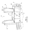
Referring to FIG. 1, one known turbine rotor or wheel 10 (partially shown) includes a male dovetail configuration 12 formed about the periphery of the wheel, with upper and lower axial projections 14, 16 (projecting outwardly from both sides of the wheel) as conventionally provided. A notch or insertion gap (not shown) with a width adequate to permit the female dovetail portion of buckets to slide over is provided. Further, an axial oriented hole 25 is provided through the notch. Buckets 18 having an airfoil 20, a platform 22 and a root or base portion 24 is shown loaded onto the wheel 10, and it will be understood that this is the last of a circumferential row of buckets to be loaded on the wheel. A closure block 26 is shown inserted over the notch, formed by removing the projections 14, 16 on opposite sides of the dovetail. A pair of tangs (one shown at 30) straddles the remaining core material of the dovetail. A retaining pin 32 is press fit into aligned openings in the core and the tangs 30. Because the stresses at the location of pin 32 are high, the closure block 26 cannot support an airfoil, and thus an undesirable space 34 is left unfilled.
-
The closure bucket typically does not have a dovetail to provide support because a dovetail would be useless in the notched space that the closure bucket occupies. Therefore, the closure bucket must be secured by other means. Various arrangements have been attempted to provide a bladed closure bucket.
-
One approach by
Reluzco et al. (U.S. 6,499,959 ) was to fix the closure bucket to adjacent buckets, i.e., the two buckets that straddle the gap and the closure bucket, in order to secure the closure bucket to the wheel. Typically, the closure bucket is attached to the adjacent buckets by pins (having a circular cross-section) extending in an axial direction engaging through the root or base portions of the adjacent buckets and the closure bucket. Here, the centrifugal load of the closure bucket is carried by the adjacent buckets through the pins. The applied loads on the closure, pins and adjacent buckets are thus not uniform. High localized stresses are encountered at the location of the pins between the closure bucket and the two adjacent buckets, i.e., along the slots receiving the pins and the pins themselves. Consequently, creep and permanent deformation of the closure bucket and/or the adjacent buckets may occur after a period of operation at high temperatures and high centrifugal loads. For example, such high temperatures and loadings may occur in the reheat section of an intermediate stage turbine. As a result, the closure bucket may tend to elongate at its base or root in response to these high temperatures and stresses over time, with the result that the slot or hole for receiving the pins may elongate in a radial outward direction.
-
To avoid creep failure, the closure bucket and preferably the two adjacent buckets are formed of a material having a higher strength, e.g., a higher creep rupture strength than the creep rupture strength of material forming the remaining buckets. For example, the remaining buckets may be typically formed of a stainless steel. The material of the closure and adjoining buckets, however, may comprise a nickel-based alloy and more particularly and preferably an Inconel-based alloy. Additionally, the pins 32 are preferably formed of a material having a higher creep rupture strength than the creep rupture strength of the remaining buckets. Thus in Reluzco, the pins are preferably formed of a similar material as the closure and adjacent buckets, although it will be appreciated that the pins may be formed of a different material having a higher creep rupture strength than the creep rupture strength of the stainless steel buckets.
BRIEF DESCRIPTION OF THE INVENTION
-
Briefly and in accordance with one aspect of the present invention, a set of bladed buckets is provided for a turbine wheel with a male dovetail. The turbine wheel includes at least one axial projection projecting outwardly from both sides of the wheel, and is formed on substantially an entire periphery of the wheel, except for being interrupted by a notch formed by removal of portions of the male dovetail at a bucket loading location on the periphery of the wheel. The set of bladed buckets includes a bladed closure bucket having a root portion, a platform and an airfoil. The root portion includes a pair of radially inwardly extending laterally spaced tangs, and at least a pair of retaining grooves having a non-circular profile. A pair of adjacent bladed buckets, one adjacent bladed bucket for assembly on each side of the bladed closure bucket, each have a root portion, a platform and an airfoil. The root portion includes at least one retaining groove having a non-circular profile and is disposed to be located opposite to one of the retaining grooves in the bladed closure bucket. At least one retaining key or retaining pin has a non-circular axial cross section, and is configured to fit into an opening defined by opposing retaining grooves in the bladed closure bucket and adjacent bladed buckets.
-
In accordance with another aspect of the present invention, a turbine wheel is provided having a male dovetail incorporating at least one axial projection projecting outwardly from both sides of the wheel, and formed on substantially an entire periphery of the wheel except for a portion interrupted by a notch formed by removal of portions of the male dovetail at a bucket loading location on the periphery of the wheel. The turbine wheel has at least one set of bladed buckets having a bladed closure bucket that includes a root portion, a platform and an airfoil. The root portion includes a pair of retaining grooves having a non-circular profile. A pair of adjacent bladed buckets, one adjacent bladed bucket for assembly on each side of the bladed closure bucket, each include a root portion, a platform and an airfoil. The root portion includes at least one retaining groove having a non-circular profile and is disposed oppositely to one of the retaining grooves in the bladed closure bucket. At least one retaining key or pin has a non-circular axial cross section, and is configured to fit into an opening defined by opposing retaining grooves in the bladed closure bucket and the adjacent bladed buckets.
-
According to a further aspect of the present invention, a closure group assembly for a turbine wheel is provided. The closure group includes a bladed closure bucket having a root portion and an airfoil. The root portion includes a pair of retaining grooves having a non-circular profile. A pair of adjacent bladed buckets, one adjacent bladed bucket for assembly on each side of the bladed closure bucket, each include a root portion and an airfoil. The root portion includes at least one retaining groove having a non-circular profile and is disposed oppositely to one of the retaining grooves in the bladed closure bucket. At least one retaining pin has a non-circular axial cross section, and is configured to fit into an opening defined by opposing retaining grooves in the bladed closure bucket and the adjacent bladed bucket.
BRIEF DESCRIPTION OF THE DRAWINGS
-
There follows a detailed description of embodiments of the invention by way of example only with reference to the accompanying drawings, in which:
- FIG. 1 illustrates a prior art unbladed closure block installed in a closure notch of a dovetailed peripheral margin of a turbine wheel;
- FIG. 2 illustrates a prior art bladed closure block with a deep cut notch in the turbine wheel;
- FIG. 3 illustrates an exemplary inventive bladed closure bucket, according to an aspect of the present invention;
- FIG. 4 illustrates an isometric view of an exemplary inventive bladed closure bucket, according to an aspect of the present invention;
- FIG. 5 illustrates an exemplary inventive bladed closure bucket standing alone on the notch of a turbine wheel, according to an aspect of the present invention;
- FIG. 6 illustrates a cross-shape cross-sectional profile for a retaining key, according to an aspect of the present invention;
- FIG. 7 illustrates a cross-shape with rounded corners cross-sectional profile for a retaining key, according to an aspect of the present invention;
- FIG. 8 illustrates a trapezoidal cross-sectional profile for a retaining key, according to an aspect of the present invention;
- FIG. 9 illustrates an elliptical cross-sectional profile for a retaining key, according to an aspect of the present invention;
- FIG. 10 illustrates a rectangular with rounded corners cross-sectional profile for a retaining key, according to an aspect of the present invention;
- FIG. 11 illustrates a Z-shaped cross-sectional profile for a retaining key, according to an aspect of the present invention;
- FIG. 12 illustrates an I-shaped cross-sectional profile for a retaining key, according to an aspect of the present invention; and
- FIG. 13 illustrates a set of buckets for a fully bladed turbine closure on a turbine wheel, according to an aspect of the present invention.
DETAILED DESCRIPTION OF THE INVENTION
-
The following embodiments of the present invention have many advantages, including improving the performance of turbine wheels by providing a fully bladed closure design.
-
The fully bladed closure design for a tangential entry dovetail utilizes three bladed buckets, including a bladed closure bucket and an adjacent bladed bucket on each side of the bladed closure bucket. The adjacent bladed buckets provide a flat skirt dovetail on their circumferential face adjacent to the bladed closure bucket. The flat skirt at the interface of the bladed closure bucket and the adjacent bladed bucket allows the full width of the flat skirt on each face to support a retaining key there-between.
-
FIG. 2 illustrates an exemplary inventive turbine wheel including a male dovetail portion on substantially an entire periphery of the wheel. The turbine wheel 100 includes a male dovetail 110 portion on substantially an entire periphery of the wheel. The male dovetail 110 may include one or more projections 125 and 130. These projections 125, 130 or hooks facilitate mating with a complementary female structure on the root of the bucket. A notch 120, formed by removal of portions of the male dovetail is located at a bucket loading location on the periphery of the wheel. As shown, the notch faces 140 form a flat surface in a generally radial direction and circumferential direction. Two bladed buckets 180 are shown mounted on the periphery of the wheel.
-
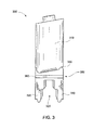
FIG. 3 illustrates a tangential view of a bladed closure bucket 300, according to an aspect of the present invention with blade or airfoil 310. Female mating surfaces 320 of the bladed closure bucket 300 are provided to seat the bucket on the notch 120 of
-
FIG. 2. The notch 120 and the female mating surfaces 320 may be provided with generally flat surfaces. Alternatively, the notch 120 and the female mating surfaces 320 of the tangs 330 may be tapered. Bladed closure bucket also includes a platform 340, which is a relatively flat portion between airfoil 310 and root portion 350. The root portion 350 may include the portion of the bucket below platform 340, including tangs 330. A retaining groove 360 is located on opposing sides of bucket 300. This retaining groove, according to aspects of the present invention, has a non-circular profile. As one example, the profile may have an elliptical shape, or half an elliptical shape as the groove defines half of an enclosed shape.
-
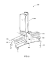
FIG. 4 illustrates an exemplary inventive bladed closure bucket 300. FIG. 5 illustrates an exemplary inventive bladed closure bucket 300 standing alone on the notch of a turbine wheel. The bladed closure bucket 300 may include a root portion 350, a platform 340 and an airfoil 310, the root portion 350 formed with a pair of radially inwardly extending laterally spaced tangs 330. The platform 340 may be adjacent to a flat skirt 445 on each circumferential face. The tangs 330 define an opening between them and are adapted to straddle the notch 120 on the turbine wheel. Each tang 330 may include inner faces complementary to the shape of the notch. The outer axial surface 455 of the root is generally flat.
-
The bladed closure bucket 300 may also include a flat surface (skirt) on each circumferential face of the root. The flat skirt 445 on each circumferential face of the root 350 includes at least one retaining groove 360, generally non-circular in shape and aligned radially with a complementary non-circular groove in the adjacent circumferential face of the adjacent bladed bucket. The retaining groove 360 extends fully across the axial width of the skirt 445. Together these grooves 360 define placement for a non-circular retaining pin or key 570 that provides support from the adjacent blades (not shown in FIG. 5) to lock the bladed closure bucket 300 in place. The terms "pin" and "key" are defined as any element passing, at least partially, through the wheel core or bucket/blade, and may be used interchangeably. By utilizing a bladed closure bucket 300 with a flat skirt 445, the key 570 will be provided support across the full width of the bucket, adding stability to the bucket and providing sufficient surface support to overcome a hook shear imposed on the bucket. The cross-sectional profile of the retaining key 570 is non-circular, and may comprise a variety of non-circular shapes. As non-limiting examples, the retaining key 570 may have a cross-sectional profile that is cross-shaped, elliptical shaped, I-shaped, polygonally shaped, rectangularly shaped, rectangular with rounded corners in shape, trapezoidally shaped, and Z-shaped. FIGs 6-12 illustrate some of the non-circular shapes that can be used for the cross-sectional profile of the retaining key 570. It is to be understood that if these shapes were divided in half (e.g., by a vertical line drawn through the center) you would obtain the cross-sectional profile of the retaining grooves 360 in the bladed closure bucket 300 and the adjacent buckets, according to some aspects of the present invention. In other embodiments, the retaining grooves may comprise more or less than half of the shapes illustrated in FIGs 6-12, as well as other shapes or non-symmetrical profiles as contemplated by aspects of the present invention.
-
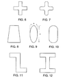
FIG. 6 illustrates a cross-shaped profile and FIG. 7 illustrates a cross-shaped profile having rounded corners. FIG. 8 illustrates a trapezoidal shaped profile and FIG. 9 illustrates an elliptical shaped profile. FIG. 10 illustrates a cross-sectional profile that is rectangular with rounded corners, but a rectangle with non-rounded corners could be used as well. FIG. 11 illustrates a Z-shaped cross-sectional profile and FIG. 12 illustrates an I-shaped cross-sectional profile. In all of the cross-sectional shapes herein described, all or a portion of the corners may be rounded and/or square as desired in the specific application.
-
One advantage provided by the present invention is the improvement of shear strength of the retaining keys. In prior art circular cross-section retaining keys the shear strength can be calculated by using the equation K = A/B, where K is the aspect ratio, A is the height of the cross-sectional profile and B is the width of the cross-sectional profile. For a circle, A is equal to B, so K is equal to 1.
-
For an oval or ellipse (see FIG. 9), the height A is greater than the width B. According to aspects of the present invention, the height and width of the cross-sectional profile can be chosen so that K equals about 1.5 to 2.5. As non-limiting examples, for a K equal to 1.5, the height of the retaining key could be 0.225" and the width of the retaining key could be 0.15", and for K equal to 2.5, the height of the retaining key could be 0.375" and the width of the retaining key could be 0.15". These dimensions are for example purposes only and any suitable height or width (as well as length) could be used as desired in the specific application.
-
The result of having non-circular retaining keys, and complementary shaped retaining grooves, can be improved shear strength in both the buckets and the retaining keys, improved load carrying capacity of the closure bucket group, reduced localized stresses in the closure bucket group.
-
FIG. 13 illustrates a set of buckets 1305 for a fully bladed turbine closure design on a turbine wheel 100. In addition to the set of buckets 1305, the turbine wheel 100 further includes a plurality of buckets (two buckets shown) 1310 assembled on the wheel to fill remaining space on the periphery. The plurality of buckets includes a root portion 1312, a platform 1314 and airfoil 1316. The root portion 1312 is formed with a female dovetail (not shown) complementary to the male dovetail 110 on the wheel 100. The male dovetail 110 is formed on substantially an entire periphery 1320 of the wheel 100, interrupted by a notch (not shown) formed by removal of portions of the male dovetail 110 at a bucket loading location on the periphery 1320 of the wheel 100.
-
The set of bladed buckets 1305 includes a bladed closure bucket 1330 including a root portion 1332, a platform 1334 and an airfoil 1336. The root portion 1332 may be formed with a pair of radially inwardly extending laterally spaced tangs, and the platform 1334 is adjacent to a flat skirt on each circumferential face. The bladed closure bucket 1330 also includes one or more retaining grooves 1338. These retaining grooves 1338 have a non-circular profile, and in FIG. 13 they are shown to have an elliptical shape (or about half an ellipse). The set of bladed buckets 1305 may also include a pair of adjacent bladed buckets 1340, one bladed bucket 1340 for assembly on each side of the bladed closure bucket 1330. The adjacent bladed bucket 1340 may include a root portion 1342, a platform 1344, an airfoil 1346 and one or more retaining grooves 1348. These retaining grooves 1348 have a non-circular profile, and in FIG. 13 they are shown to have an elliptical shape (or about half an ellipse). The root portion 1342 may be formed with a female dovetail (not shown) complementary to the male dovetail 110 on the wheel 100. The platform 1344 is formed with a flat skirt on a circumferential face adjacent to the bladed closure bucket 1330.
-
The set 1305 also includes at least one retaining key 1350 connecting the bladed closure bucket 1330 and each adjacent bucket 1340 through at least one axial hole 1360 running the full axial length of the bladed closure bucket 1330 and running the full axial length of the adjacent bucket 1340. The axial hole 1360 is formed by the combination of the retaining grooves in the bladed closure bucket and the opposing adjacent bucket 1340.
-
The retaining grooves of the adjacent buckets 1340 are radially aligned with a complementary groove on the bladed closure bucket 1330. Each of the grooves on the adjacent buckets 1340 and the bladed closure bucket 1330 are generally non-circular, and form a generally enclosed shape retaining keys 1350. More than one retaining key 1350 may be utilized at the interface between the bladed closure bucket 1330 and the adjacent buckets 1340. Flat skirts permit the retaining key or keys to maintain contact with the full axial length of the both the bladed closure bucket 1330 and the adjacent buckets 1340 along the flat skirt, providing superior contact to hold the bladed closure bucket 1330 in place.
-
The aspects of the present invention provide a closure block assembly having a fully bladed design, for reduced efficiency losses when compared to a bladeless design. The non-circular retaining keys have reduced width (compared to some circular key designs) and increased height, resulting in higher shear strength (compared to some circular key designs). The reduced width between opposing retaining grooves in the bladed closure block also results in the root of the bladed closure block having improved strength. The combined design, according to aspects of the present invention, yields lower stresses in adjacent buckets and allows for increased load carrying capacity in the closure group when compared to some circular key designs. While various embodiments are described herein, it will be appreciated from the specification that various combinations of elements, variations or improvements therein may be made, and are within the scope of the invention.
-
For completeness, various aspects of the invention are now set out in the following numbered clauses:
- 1. A set of bladed buckets for a turbine wheel with a male dovetail, said turbine wheel comprising at least one axial projection projecting outwardly from both sides of the wheel, being formed on substantially an entire periphery of the wheel and interrupted by a notch formed by removal of portions of the male dovetail at a bucket loading location on the periphery of the wheel, the set of bladed buckets comprising:
- a bladed closure bucket including a root portion, a platform and an airfoil, wherein the root portion includes a pair of radially inwardly extending laterally spaced tangs, and at least a pair of retaining grooves having a non-circular profile;
- a pair of adjacent bladed buckets, one adjacent bladed bucket for assembly on each side of the bladed closure bucket and each of said adjacent bladed buckets including a root portion, a platform and an airfoil, wherein the root portion includes at least one retaining groove having a non-circular profile and disposed to be located opposite to one of the retaining grooves in said bladed closure bucket; and
- at least one retaining key having a non-circular axial cross section, and configured to fit into an opening defined by opposing retaining grooves in said bladed closure bucket and said bladed buckets.
- 2. The set of bladed buckets of clause 1, wherein the non-circular profile of the retaining grooves in the bladed closure bucket includes at least a portion of a shape chosen from at least one of the group comprising:
- cross-shaped, elliptical, I-shaped, polygonal, rectangular, rectangular with rounded corners, trapezoidal, and Z-shaped.
- 3. The set of bladed buckets of clause 1, wherein the non-circular profile of the retaining grooves in the pair of adjacent buckets includes at least a portion of a shape chosen from at least one of the group comprising:
- cross-shaped, elliptical, I-shaped, polygonal, rectangular, rectangular with rounded corners, trapezoidal, and Z-shaped.
- 4. The set of bladed buckets of clause 1, wherein the non-circular axial cross section of the at least one retaining key has a shape chosen from at least one of the group comprising:
- cross-shaped, elliptical, I-shaped, polygonal, rectangular, rectangular with rounded corners, trapezoidal, and Z-shaped.
- 5. The set of bladed buckets of clause 1, wherein the pair of retaining grooves in the bladed closure bucket extend in an axial direction.
- 6. The set of bladed buckets of clause 5, wherein the at least one retaining groove in the pair of adjacent bladed buckets extends in an axial direction.
- 7. The set of bladed buckets of clause 6, wherein the at least one retaining key extends in the axial direction when inserted into the opening defined by opposing retaining grooves in said bladed closure bucket and said bladed buckets.
- 8. The set of bladed buckets of clause 1, wherein the turbine wheel is part of, at least one of, a steam turbine and a gas turbine.
- 9. A turbine wheel with a male dovetail, said turbine wheel comprising at least one axial projection projecting outwardly from both sides of the wheel, being formed on substantially an entire periphery of the wheel and interrupted by a notch formed by removal of portions of the male dovetail at a bucket loading location on the periphery of the wheel, said turbine wheel having at least one set of bladed buckets, said set of bladed buckets comprising:
- a bladed closure bucket including a root portion, a platform and an airfoil, wherein the root portion includes a pair of retaining grooves having a non-circular profile;
- a pair of adjacent bladed buckets, one adjacent bladed bucket for assembly on each side of the bladed closure bucket and each of said adjacent bladed buckets including a root portion, a platform and an airfoil, wherein the root portion includes at least one retaining groove having a non-circular profile and disposed oppositely to one of the retaining grooves in said bladed closure bucket;
- at least one retaining key having a non-circular axial cross section, and configured to fit into an opening defined by opposing retaining grooves in said bladed closure bucket and said bladed buckets.
- 10. The turbine wheel of clause 9, wherein the non-circular profile of the retaining grooves in the bladed closure bucket includes at least a portion of a shape chosen from at least one of the group comprising:
- cross-shaped, elliptical, I-shaped, polygonal, rectangular, rectangular with rounded corners, trapezoidal, and Z-shaped.
- 11. The turbine wheel of clause 9, wherein the non-circular profile of the retaining grooves in the pair of adjacent buckets includes at least a portion of a shape chosen from at least one of the group comprising:
- cross-shaped, elliptical, I-shaped, polygonal, rectangular, rectangular with rounded corners, trapezoidal, and Z-shaped.
- 12. The turbine wheel of clause 9, wherein the non-circular axial cross section of the at least one retaining key has a shape chosen from at least one of the group comprising:
- cross-shaped, elliptical, I-shaped, polygonal, rectangular, rectangular with rounded corners, trapezoidal, and Z-shaped.
- 13. The turbine wheel of claim 9, wherein the pair of retaining grooves in the bladed closure bucket extend in an axial direction.
- 14. The turbine wheel of clause 13, wherein the at least one retaining groove in the pair of adjacent bladed buckets extends in an axial direction.
- 15. The turbine wheel of clause 14, wherein the at least one retaining key extends in the axial direction when inserted into the opening defined by opposing retaining grooves in said bladed closure bucket and said bladed buckets.
- 16. The turbine wheel of clause 9, wherein the turbine wheel is part of, at least one of, a steam turbine and a gas turbine.
- 17. A closure group assembly for a turbine wheel comprising:
- a bladed closure bucket including a root portion and an airfoil, wherein the root portion includes a pair of retaining grooves having a non-circular profile;
- a pair of adjacent bladed buckets, one adjacent bladed bucket for assembly on each side of the bladed closure bucket and each of said adjacent bladed buckets including a root portion and an airfoil, wherein the root portion includes at least one retaining groove having a non-circular profile and disposed oppositely to one of the retaining grooves in said bladed closure bucket;
- at least one retaining pin having a non-circular axial cross section, and configured to fit into an opening defined by opposing retaining grooves in said bladed closure bucket and said adjacent bladed bucket.
- 18. The closure group assembly of clause 17, wherein the non-circular profile of the retaining grooves in the bladed closure bucket and the pair of adjacent buckets includes at least a portion of a shape chosen from at least one of the group comprising:
- cross-shaped, elliptical, I-shaped, polygonal, rectangular, rectangular with rounded corners, trapezoidal, and Z-shaped.
- 19. The closure group assembly of clause 17, wherein the non-circular axial cross section of the at least one retaining pin has a shape chosen from at least one of the group comprising:
- cross-shaped, elliptical, I-shaped, polygonal, rectangular, rectangular with rounded corners, trapezoidal, and Z-shaped.
- 20. The closure group assembly of clause 17, wherein the turbine wheel is part of, at least one of, a steam turbine and a gas turbine.