EP3765672B1 - Verdichtervorrichtungssystem und verfahren zum betrieb eines verdichtervorrichtungssystems - Google Patents
Verdichtervorrichtungssystem und verfahren zum betrieb eines verdichtervorrichtungssystems Download PDFInfo
- Publication number
- EP3765672B1 EP3765672B1 EP19709847.8A EP19709847A EP3765672B1 EP 3765672 B1 EP3765672 B1 EP 3765672B1 EP 19709847 A EP19709847 A EP 19709847A EP 3765672 B1 EP3765672 B1 EP 3765672B1
- Authority
- EP
- European Patent Office
- Prior art keywords
- unbalanced mass
- compacting
- energy
- compactor
- device system
- Prior art date
- Legal status (The legal status is an assumption and is not a legal conclusion. Google has not performed a legal analysis and makes no representation as to the accuracy of the status listed.)
- Active
Links
- 238000000034 method Methods 0.000 title claims description 64
- 230000001172 regenerating effect Effects 0.000 claims description 78
- 238000004146 energy storage Methods 0.000 claims description 56
- 230000009471 action Effects 0.000 claims description 39
- 238000003860 storage Methods 0.000 claims description 30
- 230000008859 change Effects 0.000 claims description 25
- 230000008569 process Effects 0.000 description 26
- 238000005056 compaction Methods 0.000 description 20
- 239000003990 capacitor Substances 0.000 description 11
- 230000033001 locomotion Effects 0.000 description 10
- 230000001133 acceleration Effects 0.000 description 9
- 239000011384 asphalt concrete Substances 0.000 description 7
- 230000006870 function Effects 0.000 description 7
- 239000013598 vector Substances 0.000 description 7
- 238000006243 chemical reaction Methods 0.000 description 5
- 238000002485 combustion reaction Methods 0.000 description 5
- 239000000463 material Substances 0.000 description 5
- 238000012546 transfer Methods 0.000 description 5
- 230000005540 biological transmission Effects 0.000 description 4
- 238000010586 diagram Methods 0.000 description 3
- 238000005265 energy consumption Methods 0.000 description 3
- 239000012530 fluid Substances 0.000 description 3
- 230000021715 photosynthesis, light harvesting Effects 0.000 description 3
- 230000001360 synchronised effect Effects 0.000 description 3
- 230000008901 benefit Effects 0.000 description 2
- 238000006073 displacement reaction Methods 0.000 description 2
- 230000007246 mechanism Effects 0.000 description 2
- 238000012544 monitoring process Methods 0.000 description 2
- 239000007787 solid Substances 0.000 description 2
- HBBGRARXTFLTSG-UHFFFAOYSA-N Lithium ion Chemical compound [Li+] HBBGRARXTFLTSG-UHFFFAOYSA-N 0.000 description 1
- 238000013459 approach Methods 0.000 description 1
- 238000010276 construction Methods 0.000 description 1
- 230000008878 coupling Effects 0.000 description 1
- 238000010168 coupling process Methods 0.000 description 1
- 238000005859 coupling reaction Methods 0.000 description 1
- 230000001419 dependent effect Effects 0.000 description 1
- 230000001066 destructive effect Effects 0.000 description 1
- 230000000694 effects Effects 0.000 description 1
- 230000002349 favourable effect Effects 0.000 description 1
- 230000003993 interaction Effects 0.000 description 1
- 229910001416 lithium ion Inorganic materials 0.000 description 1
- 238000012423 maintenance Methods 0.000 description 1
- 238000004519 manufacturing process Methods 0.000 description 1
- 238000013507 mapping Methods 0.000 description 1
- 238000012986 modification Methods 0.000 description 1
- 230000004048 modification Effects 0.000 description 1
- 229920000642 polymer Polymers 0.000 description 1
- 238000005381 potential energy Methods 0.000 description 1
- 230000007420 reactivation Effects 0.000 description 1
- 230000009467 reduction Effects 0.000 description 1
- 238000005096 rolling process Methods 0.000 description 1
- 238000007493 shaping process Methods 0.000 description 1
- 239000002689 soil Substances 0.000 description 1
Images


Classifications
-
- E—FIXED CONSTRUCTIONS
- E01—CONSTRUCTION OF ROADS, RAILWAYS, OR BRIDGES
- E01C—CONSTRUCTION OF, OR SURFACES FOR, ROADS, SPORTS GROUNDS, OR THE LIKE; MACHINES OR AUXILIARY TOOLS FOR CONSTRUCTION OR REPAIR
- E01C19/00—Machines, tools or auxiliary devices for preparing or distributing paving materials, for working the placed materials, or for forming, consolidating, or finishing the paving
- E01C19/22—Machines, tools or auxiliary devices for preparing or distributing paving materials, for working the placed materials, or for forming, consolidating, or finishing the paving for consolidating or finishing laid-down unset materials
- E01C19/23—Rollers therefor; Such rollers usable also for compacting soil
- E01C19/28—Vibrated rollers or rollers subjected to impacts, e.g. hammering blows
- E01C19/286—Vibration or impact-imparting means; Arrangement, mounting or adjustment thereof; Construction or mounting of the rolling elements, transmission or drive thereto, e.g. to vibrator mounted inside the roll
-
- B—PERFORMING OPERATIONS; TRANSPORTING
- B06—GENERATING OR TRANSMITTING MECHANICAL VIBRATIONS IN GENERAL
- B06B—METHODS OR APPARATUS FOR GENERATING OR TRANSMITTING MECHANICAL VIBRATIONS OF INFRASONIC, SONIC, OR ULTRASONIC FREQUENCY, e.g. FOR PERFORMING MECHANICAL WORK IN GENERAL
- B06B1/00—Methods or apparatus for generating mechanical vibrations of infrasonic, sonic, or ultrasonic frequency
- B06B1/10—Methods or apparatus for generating mechanical vibrations of infrasonic, sonic, or ultrasonic frequency making use of mechanical energy
- B06B1/16—Methods or apparatus for generating mechanical vibrations of infrasonic, sonic, or ultrasonic frequency making use of mechanical energy operating with systems involving rotary unbalanced masses
- B06B1/161—Adjustable systems, i.e. where amplitude or direction of frequency of vibration can be varied
- B06B1/166—Where the phase-angle of masses mounted on counter-rotating shafts can be varied, e.g. variation of the vibration phase
-
- E—FIXED CONSTRUCTIONS
- E01—CONSTRUCTION OF ROADS, RAILWAYS, OR BRIDGES
- E01C—CONSTRUCTION OF, OR SURFACES FOR, ROADS, SPORTS GROUNDS, OR THE LIKE; MACHINES OR AUXILIARY TOOLS FOR CONSTRUCTION OR REPAIR
- E01C19/00—Machines, tools or auxiliary devices for preparing or distributing paving materials, for working the placed materials, or for forming, consolidating, or finishing the paving
- E01C19/22—Machines, tools or auxiliary devices for preparing or distributing paving materials, for working the placed materials, or for forming, consolidating, or finishing the paving for consolidating or finishing laid-down unset materials
- E01C19/23—Rollers therefor; Such rollers usable also for compacting soil
- E01C19/28—Vibrated rollers or rollers subjected to impacts, e.g. hammering blows
- E01C19/288—Vibrated rollers or rollers subjected to impacts, e.g. hammering blows adapted for monitoring characteristics of the material being compacted, e.g. indicating resonant frequency, measuring degree of compaction, by measuring values, detectable on the roller; using detected values to control operation of the roller, e.g. automatic adjustment of vibration responsive to such measurements
-
- E—FIXED CONSTRUCTIONS
- E01—CONSTRUCTION OF ROADS, RAILWAYS, OR BRIDGES
- E01C—CONSTRUCTION OF, OR SURFACES FOR, ROADS, SPORTS GROUNDS, OR THE LIKE; MACHINES OR AUXILIARY TOOLS FOR CONSTRUCTION OR REPAIR
- E01C19/00—Machines, tools or auxiliary devices for preparing or distributing paving materials, for working the placed materials, or for forming, consolidating, or finishing the paving
- E01C19/22—Machines, tools or auxiliary devices for preparing or distributing paving materials, for working the placed materials, or for forming, consolidating, or finishing the paving for consolidating or finishing laid-down unset materials
- E01C19/30—Tamping or vibrating apparatus other than rollers ; Devices for ramming individual paving elements
- E01C19/34—Power-driven rammers or tampers, e.g. air-hammer impacted shoes for ramming stone-sett paving; Hand-actuated ramming or tamping machines, e.g. tampers with manually hoisted dropping weight
- E01C19/38—Power-driven rammers or tampers, e.g. air-hammer impacted shoes for ramming stone-sett paving; Hand-actuated ramming or tamping machines, e.g. tampers with manually hoisted dropping weight with means specifically for generating vibrations, e.g. vibrating plate compactors, immersion vibrators
Definitions
- the present invention relates to a compactor device system. Furthermore, the present invention relates to a method for operating a compactor device system and a compactor vehicle.
- Asphalt concrete is used to surface roads, parking lots or airports. Once a layer of asphalt concrete has been provided on the prepared surface, it is to be compacted such that the finished road has the desired performance characteristics in terms of durability in turn affecting tire wear, road noise and so on.
- a road roller being a compactor vehicle, comprising a compactor device system like a compactor drum, needs to pass several times over a single spot on the surface in order to achieve the desired compaction.
- an unbalanced mass or multiple unbalanced masses, are commonly provided in a compactor drum of the road roller such that forces caused by the rotation of the unbalanced masses contribute to the compaction in addition to the weight of the road roller.
- multiple passes of the road roller over a single spot are needed to obtain the desired compaction.
- the direction of movement of the road roller conventionally changes from forward to backward between two succeeding passes of the road roller over a single spot.
- common road rollers have two compacting drums provided with an unbalanced mass each and comprise between the front compactor drum and the aft compactor drum a steering joint allowing to tilt the rotational axis of the front compactor drum and the rotational axis of the aft compactor drum with respect to each other essential in a plane parallel to the ground allowing a steering of the road roller.
- the prior art compactor device system has a compactor drum rotatable about a drum axis and a first unbalanced mass comprising a first shaft having a first eccentricity and a second unbalanced mass comprising a second shaft having a second eccentricity.
- the first and second unbalanced masses are provided within the compactor drum.
- the first unbalanced mass is rotatable about a first rotational axis and the second unbalanced mass is rotatable about a second rotational axis.
- the first and second rotational axes extend parallel to the drum axis on diametrically opposed sides of the drum axis.
- a drive is operable to drive the first unbalanced mass by means of a first transmission loop and to drive the second unbalanced mass by means of a second transmission loop.
- a (first) phase shifting arrangement is adapted to alter the path of the first transmission loop for shifting the phase of rotation of the first unbalanced mass.
- second phase shifting arrangement which is adapted to alter the path of the second transmission loop for shifting the phase of rotation of the second unbalanced mass.
- a device for generating mechanical vibration is known from US 6,717,379 B1 .
- the creation of mechanical vibration is made with a system of two or more rotating eccentrics.
- Each eccentric is rotated by an individually controlled motor and the angle position of each eccentric is read by an angle sensor.
- the rotation frequency, direction of rotation and phase position of each eccentric can be controlled.
- a force vector diagram of suitable form, in space and time can be generated.
- the device is intended primarily for use in appliances for dynamic compaction of various materials.
- a compaction roller vibratory mechanism is known from EP 2 147 725 A1 .
- a vibratory mechanism of a drum of a compaction roller consists of an outer eccentric weight, an inner eccentric weight, a friction clutch, and a hydraulic connection of hydromotors.
- the eccentric weights are pivoted and coaxially mounted against each other on unidentified shafts connected with the hydromotors.
- Sensors of a mutual angular displacement of eccentric weights are situated on shafts associated to the eccentric weights.
- a control unit together with related components is adapted to act on the hydraulic connection of the hydromotors to allow a slipping movement of the friction clutch, thereby achieving a mutual displacement of one eccentric weight against the order.
- the document DE 10 2011 195 899 A1 discloses a compaction device driven by an electric motor, having a rechargeable storage unit for electrical power, and a vibration-damped guide device. Also a method for compaction control is disclosed which derives an degree of compaction on basis of determining the power of the electric motor.
- An adjustable vibration cylinder for a road roller is known from US 3,192,839 corresponding to DE-AS 1 267 623 .
- a vibrating arrangement has two inertia or unbalancing weights which are driven with the same speed in opposite directions.
- a working device for generating a working movement is known from DE 10 2011 102 553 A1 .
- the known device has a drive train with an internal combustion engine and with a motion conversion device for converting a rotational movement of the internal combustion engine into a working movement.
- a load device is coupled to the drive train for exerting a load on the drive train on demand for avoiding an oversupply of energy and for avoiding that the speed of the internal combustion engine increases beyond an allowed value.
- the load device comprises an energy buffer or storage for storing energy which is withdrawn from the drive train, and the load device is adapted to pass stored energy back into the drive train by means of an electric motor.
- the possibility of a fly wheel storage is mentioned, e.g. of a kind using the rotor of the electric motor as fly wheel.
- US 2015/152606 A1 discloses a soil compaction machine in the form of a vibration compactor, which comprises a vibration exciter for generating different kinds of exciter vibration having a first and a second imbalance shaft, which are arranged in parallel to one another.
- Each imbalance shaft is driven via a separate motor, so that the rotational velocity, the rotational direction, and the phase relation of each of the imbalance shafts can be changed separately.
- the object of the present invention is therefore to provide a compactor device system and a method for using a compactor device system reducing energy consumption during operation of the compactor device system.
- the present invention provides the compactor device system defined in claim 1 and the method for operating a compactor device system defined in claim 8.
- Preferred embodiments of the invention are defined in the dependent claims and are indicated to the skilled reader in the following description.
- the invention and preferred embodiments thereof achiever further advantages, such as to provide a compactor device system which allows to accelerate the operation of the compactor device system, to provide a compactor device system having a relatively simple structure, to provide a compactor device system and a method for using a compactor device system allowing a variation of the intensity of a compacting action of a compacting tool of the compactor device system, and to provide a compactor vehicle and a method of operating a compactor vehicle resulting in reduced structural stress of the compactor vehicle during its use.
- An additional object of the present invention is the provision of a simple and cost-effective method of measuring ground compaction.
- a compactor device system comprising a compacting tool; a first driving means; a first unbalanced mass rotatable by the first driving means at a first rotation frequency; a second driving means; a second unbalanced mass rotatable by the second driving means at a second rotation frequency.
- Each of the first and second unbalanced mass when rotated by the respective driving means, is adapted to apply a respective oscillating force on the compacting tool.
- a control unit is adapted to control the first rotation frequency and the second rotation frequency, such that the first rotation frequency equals the second rotation frequency; and is further adapted to control a relative phase between a rotation of the first unbalanced mass and a rotation of the second unbalanced mass.
- the control unit is further adapted to drive the compactor device system in a compacting mode by setting the relative phase to such a value, that forces created by rotation of the first unbalanced mass and forces created by rotation of the second unbalanced mass both contribute to a compacting action of the compacting tool.
- the first unbalanced mass and the second unbalanced mass are operable as a flywheel energy storage in at least one operation mode of the compactor device system.
- the flywheel energy storage is adapted to store a rotational energy of the rotating first unbalanced mass and a rotational energy of the second rotating unbalanced mass.
- the compactor device system has have a recuperation arrangement which is adapted to store energy generated by regenerative braking in the flywheel energy storage and to withdraw energy stored in the flywheel energy storage for driving or supporting at least one function of the compactor device system. Therefore, the energy consumption of the compactor device system can be reduced.
- control unit is further adapted to drive the compactor device system in a non-compacting mode by setting the relative phase to such a value, that forces created by rotation of the first unbalanced mass and forces created by rotation of the second unbalanced mass add destructively for achieving minimum or no compacting action of the compacting tool, wherein the first unbalanced mass and the second unbalanced mass are operable as said flywheel energy storage at least in the non-compacting mode.
- the compacting tool comprises a compactor drum which is arranged to be rotable about a drum axis and is adapted to directly contact the object or surface to be compacted, wherein the recuperation arrangement with the compactor drum and the flywheel energy storage are operable to rotationally drive or accelerate at least one of the first unbalanced mass and the second unbalanced mass on basis of rotational energy of the compactor drum and to rotationally drive or accelerate the compactor drum on basis of energy stored in the flywheel energy storage.
- the first rotation frequency equals the second rotation frequency means equality of the absolute value of the rotation frequencies and the rotational direction. During the process of switching from one of the non-compacting mode and the compacting mode to the other one of the non-compacting mode and the compacting mode, the first rotation frequency is not equal the second rotation frequency.
- the compacting tool comprises a compactor drum which is arranged to be rotable about a drum axis and is adapted to directly contact the object or surface to be compacted, wherein the first unbalanced mass and the second unbalanced mass are arranged concentrically within the compactor drum and rotatable about said drum axis which is common rotational axis of the compactor drum and the first and second unbalanced masses.
- a compactor device system having a relatively simple structure is provided.
- control unit is further adapted to drive the compactor device system in the compacting mode by setting the relative phase to an intermediate value, preferably a selected one of plural intermediate values or within an intermediate value range, between the/a first value, which provides that forces created by rotation of the first unbalanced mass and forces created by rotation of the second unbalanced mass add constructively for achieving maximum compacting action of the compacting tool and the/a second value, which provides that forces created by rotation of the second unbalanced mass add destructively for achieving minimum or no compacting action of the compacting tool, such that for the intermediate value being set forces created by rotation of the first unbalanced mass and forces created by rotation of the second unbalanced mass contribute to compacting action of the compacting tool.
- an intermediate value preferably a selected one of plural intermediate values or within an intermediate value range
- control unit is adapted to change the rotation frequency of at least one of the first unbalanced mass and the second unbalanced mass such that the value of the relative phase changes from a value having been set to another value to be set, preferably to switch from one of the non-compacting mode and the compacting mode to the other one of the non-compacting mode and the compacting mode or to change the intensity of the compacting action of the compacting tool.
- the compactor device system described herein can further comprise a third driving means, wherein the compacting tool is a compactor drum adapted to directly contact the object or surface to be compacted, and wherein the compacting tool is rotatable by the third driving means; a third regenerative braking device adapted to convert rotational energy of the compacting tool into recuperation energy, in particular into electrical recuperation energy; wherein the compactor device system is adapted to store recuperation energy obtained from converting rotational energy of the compacting tool in the flywheel energy storage by accelerating the a first unbalanced mass using the first driving means and the second unbalanced mass using the second driving means in the non-compacting mode.
- Such a system further reduces significantly the energy consumption resulting in the possibility of using a smaller combustion engine, compared with a conventional compactor device system, for powering the compactor device system, reducing costs and overall emissions.
- the compactor device system can further comprise a first regenerative braking device adapted to convert rotational energy of the first unbalanced mass into recuperation energy, in particular into electrical recuperation energy; or/and a second regenerative braking device adapted to convert rotational energy of the second unbalanced mass into recuperation energy, in particular into electrical recuperation energy; and preferably a storage device adapted to sore the recuperation energy; wherein the compactor device system is adapted to accelerate the compacting tool using recuperation energy obtained from the first or/and second regenerative braking device, which has preferably been stored in the storage device.
- recuperation energy is potential energy stored in compressed air or any other compressible fluid.
- the conversion of the rotation energy of an unbalanced mass into this form of recuperation energy can be done by driving directly a pump, e.g. switchable by a clutch, increasing a pressure in a tank.
- the high pressure fluid stored in the tank can be used to drive one of the unbalanced masses e.g. by using the pump as a turbine, driven by the high pressure fluid.
- the pump can be a regenerative braking device or/and a driving means.
- regenerative braking devices provide electrical power which can be stored using a battery like a lithium ion polymer battery, a capacitor or a super capacitor and so on.
- the compactor device system may further comprise at least one of: a first regenerative braking device adapted to convert rotational energy of the first unbalanced mass into recuperation energy, in particular into electrical recuperation energy, wherein preferably the first regenerative braking device is comprised by the first driving means; a second regenerative braking device adapted to convert rotational energy of the second unbalanced mass into recuperation energy, in particular into electrical recuperation energy, wherein preferably the second regenerative braking device is comprised by the second driving means; and a third regenerative braking device adapted to convert kinetic energy, preferably rotational energy, of the compacting tool into recuperation energy, in particular into electrical recuperation energy, wherein preferably the third regenerative braking device is comprised by a third driving means of the compactor device system adapted to drive the compacting tool.
- a plurality or all of the regenerative braking devices are provided, it is possible to reuse energy obtained from the regenerative braking device(s) to accelerate one or both of the unbalanced masses or/and the compacting tool in case one or both of the unbalanced masses or/and the compacting tool needs to be accelerated.
- Such systems are most versatile in case the kinetic energy is converted into electrical energy, referred to as electrical recuperation energy, since the energy transfer from a regenerative braking device to a storage means, or from a storage means to a drive means can be performed by conventional cables and power electronics.
- electrical recuperation energy since the energy transfer from a regenerative braking device to a storage means, or from a storage means to a drive means can be performed by conventional cables and power electronics.
- the provision of such systems is well known in the field of hybrid vehicles and further details are omitted since those systems form part of the general knowledge of a person skilled in the art.
- At least one, preferably all of the first driving means and the second driving means, and preferably in addition a third driving means of the compactor device system adapted to drive the compacting tool is an electric driving means, e.g. a respective electric motor, which preferably is adapted to be a regenerative braking device by being adapted to be used as a generator in a generator mode.
- an electric driving means e.g. a respective electric motor
- simple and reliable driving means like electrical motors are used which require essentially no or only minor modifications in order to be used as a regenerative braking device.
- At least one of the first driving means, the second driving means and the third driving means of the compactor device is a corresponding first, second or third regenerative braking device, adapted to convert the corresponding kinetic energy of the first unbalanced mass or the second unbalanced mass or the compacting tool into recuperation energy, preferably into electrical recuperation energy, wherein preferably the compactor device system is adapted to supply the recuperation energy to a flywheel energy storage, preferably comprising a first unbalanced mass and the second unbalanced mass.
- a compactor device system according to an aspect of the present disclosure is possible to switch from the compacting mode to the non-compacting mode, and vice versa, by at least decelerating one of the first or second unbalanced masses in order to change the relative phase between the rotations of these masses.
- the compactor device system discussed above is adapted to reuse energy obtainable in such a deceleration.
- the first, second or third regenerative braking device are formed by a corresponding electric motor adapted to be used as an electric generator, since recuperation energy obtained by the regenerative braking device can be distributed to another driving means or storage of electrical energy like a capacitor or battery without any further energy-form conversion accompanied by losses.
- the compactor device system can comprise a first regenerative braking device adapted to convert rotational energy of the first unbalanced mass into recuperation energy, in particular into electrical recuperation energy; and a storage device for recuperation energy.
- the storage device is preferably adapted to store the recuperation energy provided by those regenerative braking devices as well.
- Such a compactor device system has particular means for obtaining recuperation energy and for storage of recuperation energy allowing reduction of total energy use due to energy storage and the possibility to reuse of the stored energy.
- the driving means can be an electrical driving means like an electric motor. Therefore it is preferable that the storage device is a capacitor, supercapacitor or a battery.
- the storage device is part of a AC/AC-converter, in particular of a variable-frequency drive, of the compactor device system, adapted to drive at least one, preferably all driving means, wherein each driving means is preferably an electric driving means, e.g. an electric motor.
- AC/AC-converters already comprise a storage device in the DC part of the AC/AC-converter, such a storage device can either be used directly for storing electrical recuperation energy obtained from a regenerative braking device, like an electric motor adapted to be driven as a generator, or such a storage device can be provided with an enlarged capacity compared to conventional AC/AC-converters, allowing a simple implementation of the storage device.
- the AC/AC-converter comprises, preferably for each driving means, an AC-power input-side, e.g. an first rectifier/inverter-unit, an intermediate section preferably formed as a DC-section or DC-link, and an AC-power output-side, e.g. a second rectifier/inverter-unit, wherein the AC-power output-side is adapted to receive AC-power and to transfer DC-power to the storage device, preferably via parts of the DC-section, the storage device being preferably formed by a capacitor, supercapacitor or a battery of the intermediate section, and the storage device can be part of the AC/AC-converter, e.g. of the DC-section or DC-link.
- an AC-power input-side e.g. an first rectifier/inverter-unit
- an intermediate section preferably formed as a DC-section or DC-link
- an AC-power output-side e.g. a second rectifier/inverter-unit
- the electrical energy to be stored in the storage device is provided in the appropriate DC form already by the AC/AC-converter and no conversion loss introducing additional rectifier, associated with the storage device and rectifying an output of the AC/AC-converter needs to be provided.
- first unbalanced mass and the second unbalanced mass are arranged coaxially, preferably concentrically, in particular as concentric drums rotatably connected to the compacting tool, wherein the compacting tool preferably is formed as a compactor drum adapted to directly contact the object or surface to be compacted, wherein in particular the first unbalanced mass is a first unbalanced drum, the second unbalanced mass is a second unbalanced drum, and wherein the compactor drum, the first unbalanced drum and the second unbalanced drum are arranged concentrically.
- This arrangement of the first and second unbalanced mass and of preferably the compacting tool provides a compact arrangement of those elements resulting in a small and space efficient compactor device system.
- one, in particular only one, of the first driving means and the second driving means and preferably of a third driving means of the compactor device system adapted to drive the compacting tool is hydraulically powered, and preferably formed as a hydraulic motor.
- This embodiment allows the use of well-known and reliable driving means for the compactor device system increasing its reliability.
- control unit is adapted to switch from one of the/a non-compacting mode and the/a compacting mode to the other one of the non-compacting mode and the compacting mode or/and is adapted to change the intensity of the action of the compacting tool by being adapted to carry out a step of changing the relative phase, wherein preferably the step of changing the relative phase comprises commanding a first step of changing the rotation frequency of the first unbalanced mass, followed by commanding a second step of changing the rotation frequency of the first unbalanced mass or/and the rotation frequency of the second unbalanced mass, wherein after the first step of changing the rotation frequency of the first unbalanced mass and the second step of changing the rotation frequency of the first unbalanced mass or/and the rotation frequency of the second unbalanced mass, the thus obtained rotational frequency of the first unbalanced mass is equal to the thus obtained rotational frequency of the second unbalanced mass.
- Such a compactor device system allows to switch between the compacting mode and non-compacting mode with a simple control scheme, since the rotational frequency of the first unbalanced mass and the rotational frequency, present before the step of changing the relative phase has started, may be different from the thus obtained rotational frequency of the first unbalanced mass and the thus obtained rotational frequency of the second unbalanced mass, present once the step of changing the relative phase has been carried out.
- the compactor device system further comprises a first regenerative braking device; and preferably further an energy management system; wherein the compactor device system is adapted to carry out the first step of changing the rotation frequency of the first unbalanced mass by decelerating the rotation of the first unbalanced mass by converting rotational energy of the first unbalanced mass into recuperation energy, in particular into electrical recuperation energy, using the first regenerative braking device; and wherein preferably the energy management system is adapted to store the recuperation energy obtained during decelerating the rotation of the first unbalanced mass by the first regenerative braking device.
- Such a system allows to store energy, which would be conventionally lost during switching from between the non-compacting mode and the compacting mode.
- the compactor device system is adapted to carry out the second step of changing the rotation frequency of the first unbalanced mass by accelerating, in particular using a recuperation energy, which is preferably stored in the energy management system, the rotation of the first unbalanced mass by means of the first driving means, preferably until the first rotation frequency is reached by the first unbalanced mass.
- Energy does not need to be stored outside the energy management system, but can be stored in an internal capacitor, battery or similar, and thus less successive steps of storing and withdrawing of energy are carried out in order to finish the step of switching between the non-compacting mode and the compacting mode, wherein each additional step of storing and withdrawing of energy would lead to energy losses.
- an external energy storage may be provided, if desired.
- the present invention further provides a method for operating a compactor device system, preferably a compactor device system as described above, the compactor device system comprising a compacting tool; a first driving means; a first unbalanced mass rotatable by the first driving means at a first rotation frequency; a second driving means; a second unbalanced mass rotatable by the second driving means at a second rotation frequency; wherein each of the first and second unbalanced mass, when rotated by the respective driving means, is adapted to apply a respective oscillating force to the compacting tool; a control unit adapted to control the first rotation frequency and the second rotation frequency, such that the first rotation frequency equals the second rotation frequency; and further adapted to control a relative phase between a rotation of the first unbalanced mass and a rotation of the second unbalanced mass.
- the method comprises the steps of: rotating the first unbalanced mass at a first first rotation frequency, rotating the second unbalanced mass at a second rotation frequency; controlling the first rotation frequency to be equal to the second rotation frequency; driving the compactor device system in a compacting mode by setting the relative phase to such a value that forces created by rotation of the first unbalanced mass and forces created by rotation of the second unbalanced mass both contribute to a compacting action of the compacting tool.
- the first unbalanced mass and the second unbalanced mass are operated as a flywheel energy storage in at least one operation mode of the compactor device system, wherein the flywheel energy storage stores a rotational energy of the rotating first unbalanced mass and a rotational energy of the second rotating unbalanced mass.
- the method comprises the step to store energy generated by regenerative braking in the flywheel energy storage and the step to withdraw energy from the flywheel energy storage for driving or supporting at least one function of the compactor device system. This method provides advantages corresponding to those of the compactor device system according to the present invention.
- the compactor device system is driven in a non-compacting mode by setting the relative phase to such a value that forces created by rotation of the first unbalanced mass and forces created by rotation of the second unbalanced mass add destructively for achieving minimum or no compacting action of the compacting tool, wherein the first unbalanced mass and the second unbalanced mass are operable as said flywheel energy storage at least in the non-compacting mode.
- the compacting tool may comprise a compactor drum which is arranged to be rotable about a drum axis and is adapted to directly contact the object or surface to be compacted.
- the method may comprise to rotationally drive or accelerate at least one of the first unbalanced mass and the second unbalanced mass on basis of rotational energy of the compactor drum and may comprise to rotationally drive or accelerate the compactor drum on basis of energy stored in the flywheel energy storage.
- the method may comprise to drive the compactor device system in the compacting mode by setting the relative phase to an intermediate value, preferably a selected one of plural intermediate values or within an intermediate value range, between the/a first value, which provides that forces created by rotation of the first unbalanced mass and forces created by rotation of the second unbalanced mass add constructively for achieving maximum compacting action of the compacting tool and the/a second value, which provides that forces created by rotation of the second unbalanced mass add destructively for achieving minimum or no compacting action of the compacting tool, such that for the intermediate value being set forces created by rotation of the first unbalanced mass and forces created by rotation of the second unbalanced mass contribute to compacting action of the compacting tool.
- an intermediate value preferably a selected one of plural intermediate values or within an intermediate value range
- the method may comprise to change the rotation frequency of at least one of the first unbalanced mass and the second unbalanced mass such that the value of the relative phase changes from a value having been set to another value to be set, preferably to switch from one of the non-compacting mode and the compacting mode to the other one of the non-compacting mode and the compacting mode or to change the intensity of the compacting action of the compacting tool.
- the compactor device system is further comprising a third driving means, wherein the compacting tool is a compactor drum adapted to directly contact the object or surface to be compacted, and a third regenerative braking device adapted to convert rotational energy of the compacting tool into recuperation energy, in particular into electrical recuperation energy; wherein in the non-compacting mode the first unbalanced mass and the second unbalanced mass form a flywheel energy storage adapted to store a rotational energy of the rotating first unbalanced mass and a rotational energy of the second rotating unbalanced mass, the method further comprising the steps of: rotating the compacting tool by the third driving means; obtaining recuperation energy from the third regenerative braking device by converting rotational energy of the compacting tool into recuperation energy; preferably storing the recuperation energy in a storage device of the compactor device system; supplying the recuperation energy to supply the flywheel energy storage.
- the method discussed above allows to reuse energy obtained in a deceleration of the compact
- the compactor device system is further comprising a first regenerative braking device adapted to convert rotational energy of the first unbalanced mass into recuperation energy, in particular into electrical recuperation energy; a second regenerative braking device adapted to convert rotational energy of the second unbalanced mass into recuperation energy, in particular into electrical recuperation energy; the method further comprising the steps of: rotating the first unbalanced mass and the second unbalanced mass in the non-compacting mode; obtaining first recuperation energy from the first regenerative braking device by converting rotational energy of the first unbalanced mass into recuperation energy; obtaining second recuperation energy from the second regenerative braking device by converting rotational energy of the second unbalanced mass into recuperation energy; preferably storing the first recuperation energy or/and the second recuperation energy in a storage device of the compactor device system; accelerating the compacting tool using first and second recuperation energy, e.g. by means of a third driving means of the compactor device system.
- Such a method uses well known and reliable means in order to gain recuperation energy from the unbalanced masses and uses it for driving or accelerating of the compacting tool.
- the present invention also provides a compactor vehicle comprising: a first compactor device system, as described above, adapted to generate a first oscillating force acting on at least some of mounting elements of the compactor vehicle for the first compactor device system; a second compactor device system, as described above, adapted to generate a second oscillating force acting on at least some of mounting elements of the compactor vehicle for the second compactor device system; and a master control unit adapted to control a relative orientation of the first and second oscillating force, preferably adapted to control the relative orientation of the first and second oscillating force such that the first and second oscillating force are parallel.
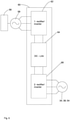
- Fig. 1 shows a compactor vehicle 20, e.g. a road roller, comprising a first compactor device system 22 and a second compactor device system 24 as well as a master control unit 26 adapted to control the concurrence of the first 22 and second 24 device system as will be described below.
- the first 22 and second 24 compactor device system can essentially show the same features and thus, only the first compactor device system 22 will be described in details.
- the compactor device system 22 comprises a compacting tool 28, which can be a compactor drum 30 as commonly used in road rollers.
- a first unbalanced mass 32 rotatable by a first driving means 34 and a second unbalanced mass 36 rotatable by a second driving means 38.
- the first and second driving means 34 and 38 may be supported on a first holding element 40 such that the first unbalanced mass 32 and the second unbalanced mass 36 are supported via the corresponding first and second driving means 34 and 38 on the first holding element 40.
- the first holding element 40 can be connected to a frame of the compactor vehicle 20.
- first unbalanced mass 32 can be rotatably supported by a first bearing element 42 and a second holding element 46 and the second unbalanced mass 36 can be supported by a second bearing element 44 on the second holding element 46, which can be connected to a frame of the compactor vehicle 20.
- the compacting tool 28 can be rotatably supported by a third bearing element 52 on the second holding element 46.
- Each of the first, second and third bearing elements 42, 44 and 52 can be a rolling element bearing.
- Each of the first and second driving means 34 and 38 can be an electric motor with a toroidal construction, like the torque motor, or each of the first and second driving means 34 and 38 can comprise external teeth provided on the outer surface of the first and/or second unbalanced mass, meshing with a gear supported on the first holding element 40 and driven by an electric motor with a drivetrain supported by the first holding element 40.
- the first and second driving means 34 and 38 may comprise bearing elements in order to support the corresponding first or second unbalanced mass 32 and 36 rotatably on the first holding element 40.
- the first unbalanced mass 32 comprises a mass bearing section 32A, a bearing section 32B and a driven section 32C, wherein preferably each of these sections is axially symmetric, in particular with regard to the same axis, represented by a dot dash line in Fig. 2 .
- the mass bearing section 32A bears an eccentric section 32D or a section having a different density, formed for example by introduction of more dense material than the surrounding material, both sections can be essentially extend along an extension direction of the first unbalanced mass 32. Is to be noted that the eccentric section 32D is not shown in the schematic cross-section of Fig. 2 .
- the second unbalanced mass 36 is provided within a cavity 32K of the first unbalanced mass 32.
- the second unbalanced mass 36 comprises a mass bearing section 36A, a bearing section 36B and a driven section 36C.
- the mass bearing section 36A bears an eccentric section 36D or a section having a different density, formed for example by introduction of more dense material than the surrounding material, both sections can be essentially extend along an extension direction of the second unbalanced mass 36.
- the second unbalanced mass 36 and its parts have preferably the same functions or/and forms or/and arrangement as the corresponding sections 32, 32A to 32D of the first unbalanced mass 32 and therefore a further description is omitted.
- the bearing section 32B preferably is connected via the first bearing element 42 to the second holding element 46 and the driven section 32C is preferably connected via the first driving means 34 to the first holding element 40.
- the bearing section 36B preferably is connected via the second bearing element 44 to the second holding element 46 and the driven section 36C is preferably connected via the second driving means 38 to the first holding element 40.
- the compactor device system 22 comprises a control unit, which may be part of the master control unit 26, but may also be provided separately from the master control unit 26.
- the control unit is adapted to control a relative phase between a rotation of the first unbalanced mass 32 and the second unbalanced mast 36.
- the first unbalanced mass 32 and the second unbalanced mass 36 are arranged coaxially, preferably concentrically as shown in figure 1 .
- the provision of eccentric sections 32D and 36D does not prevent in the context of this application that the first unbalanced mass 32 and the second unbalanced mass 36 are arranged coaxially or concentrically.
- the compacting tool 28 is formed as a compactor drum 30, it is preferred that the first unbalanced mass 32, the second unbalanced mass 36 and the compactor drum 30 are arranged coaxially, preferably concentrically as shown in Figs. 1 and 2 .
- Those unbalanced masses 32 and 36 can have essentially the shape of a drum and can be labeled as unbalanced drums.
- the absolute phase of the rotation of the first/second unbalanced mass is the rotation angle acquired over time during the rotation of the first/second unbalanced mass, such that if the unbalanced mass rotates once about 360°, the total phase is 2 ⁇ . In case the unbalanced mass rotates two times about 360°, the total phase is 4 ⁇ , and so on.
- the control unit 50 can receive the absolute angle of the first unbalanced mass 32 and the absolute angle second unbalanced mass 36 from respective rotary encoders mounted on the first unbalanced mass and the second unbalanced mass (not shown in the figures) with respect to a predetermined reference position of the corresponding mass.
- the control unit 50 can be adapted to control the first rotation frequency and the second rotation frequency on the basis of the absolute angles measured and a timing signal, which is preferably generated by the control unit 50.
- the eccentric section 32D and 36D are aligned with respect to each other as shown in Fig. 1 for the first compactor device system 22.
- the forces created by the first unbalanced mass and the second unbalanced mass 32 and 36 being essentially centrifugal forces, point in the direction of the respective eccentric section 32D and 36D.
- the compactor device system 22 is a compacting mode when the control unit 50 sets the relative phase ⁇ ⁇ to 0 (0 being a first value of the relative phase) and keeps (controls) this value constant.
- Such a ratio of masses and radiuses can be chosen as starting point for optimizing positioning, weight and shaping of the eccentric sections.
- the control unit 50 can receive different target values from an operator of the compactor device system inputting a requested ⁇ ⁇ , for example being 0° or 180°, alternatively the operator can select a compacting mode, resulting in the control unit 50 setting ⁇ ⁇ to 0°, or a non-compacting mode, resulting in the control unit 50 setting ⁇ ⁇ to 180°, such that the control unit 50 is adapted to switch from compacting mode to the non-compacting mode and vice versa.
- the compacting mode is being used when the road roller travels on the road surface to be compacted.
- the process of compacting the road surface comprises passing multiple times by the road roller over the surface to be compacted. Therefore, between passes, the driving direction of the road roller needs to change. This process comprises bringing the road roller to a halt and changing its moving direction from forward to backward. In particular at the instant of standing, a continuation of the compacting mode is not desired since the compacting tool would create a dent in the surface to be compacted.
- the compactor vehicle 20 using a compactor device system switches the compactor device system from the compacting mode to the non-compacting mode in the process of changing the direction from forward to backward.
- This change uses only a minor amount of energy when changing the relative phase between the rotation of the first unbalanced mass 32 and the rotation of the second unbalanced mass 36, since introduction of significant changes in the rotation frequency of the first unbalanced mass 32 and second unbalanced mass 36 is avoided while the combined forces created by the rotation of the unbalanced masses is essentially zero which reduces the compacting action of the road roller.
- the compacting mode is being reengaged by changing the relative phase of the rotation of the first unbalanced mass 32 and second unbalanced mass 36, again requiring only a minor amount of energy since no significant change in the rotation frequency of the first unbalanced mass 32 and the rotation of the second unbalanced mass 36 needs to be introduced during re-engaging of the compacting mode.
- the process of changing the direction of movement of road roller during the compacting process requires less energy.
- the process of changing the relative phase between a rotation of the first unbalanced mass and the rotation of the second unbalanced mass, carried out twice in the above process has been found by the inventors to be much faster compared with bringing a rotating unbalanced mass to a hold and then accelerating the unbalanced mass to a desired rotation frequency within the parameters, used for rotation of unbalanced mass in compacting device systems.
- the compactor device system according the invention enables faster change of direction of the compactor vehicle 20 in the process of compacting a surface.
- the above-described compactor device system 22 can be operated by a method comprising the steps of rotating the first unbalanced mass 32 at first rotation frequency ⁇ 1 , rotating the second unbalanced mass 36 at a second rotation frequency ⁇ 2 . This is indicated by the solid arrows on the first unbalanced mass 32 and the second unbalanced mass 36 in Fig. 4 .
- the method further comprises the steps of: controlling the first rotation frequency ⁇ 1 to be equal to the second rotation frequency ⁇ 2 and driving the compactor device system 22 in the compacting mode by setting the relative phase to a first value, preferably, setting the relative phase to 0°, driving the compactor device system in the non-compacting mode by setting the relative phase to a second value, preferably by setting the relative phase to 180°, Fig. 4 , right side (rotation of the unbalanced masses is not indicated further), and mode switching from one of the non-compacting mode and the compacting mode to the other one of the non-compacting mode and the compacting mode.
- the switching from the non-compacting mode to the compacting mode is indicated in Fig.
- the position change of the eccentric sections 32D and 36D during mode switching from the non-compacting mode to the compacting mode is preferably induced by controlling of the first and second driving means 34 and 38, in particular by decelerating one of the first 32 and second 36 unbalanced masses and accelerating this unbalanced mass e.g. under the control of PID algorithm, such that the relative phase is 180° after the acceleration.
- the mode switching from the compacting mode to the non-compacting mode can be carried out essentially in the same manner, however, after the acceleration of the previously decelerated unbalanced mass the relative phase is 0°.
- the first unbalanced mass 32 and second unbalanced mass 36 preferably form part of a flywheel energy storage storing rotational energy of the rotating first unbalanced mass 32 and the second unbalanced mass 36 without energy dissipation due to work done by the oscillating force resulting from rotation of the first unbalanced mass 32 and of the second unbalanced mass 36.
- Energy is only being lost by friction of the first unbalanced mass 32 and a second unbalanced mass 36 and by work been done by forces due to residual unbalance of the combination of the first unbalanced mass 32 and second unbalanced mass 36 in the non-compacting mode.
- the compactor device system 22 comprises further a third driving means 54 driving the compactor tool 28 or drum 30 which is adapted to directly contact object or surface to be compacted.
- the third driving means 54 can drive the compactor drum 30 by rotating the compactor drum 30.
- the compactor device system 22 preferably comprises a third regenerative braking device which is adapted to convert rotational energy of the compacting tool 28 into recuperation energy, in particular into electrical recuperation energy.
- the third driving means 54 comprises an electric motor adapted to be used as an electric generator in a generator mode such that the third regenerative braking device can be part of the third driving means and the conversion of rotational energy of the compacting tool is being performed by the electric motor used as an electric generator.
- the compactor device system 22 is adapted to store the recuperation energy obtained from the third regenerative braking device in the flywheel energy storage by using the energy obtained by the third regenerative braking device to accelerate the first unbalanced mass 32 and the second unbalanced mass 36 by the corresponding first and second driving means while the compactor device system is the non-compacting mode.
- the compactor device system 22 can comprise a first regenerative braking device adapted to convert rotational energy of the first unbalanced mass 32 into recuperation energy, in particular into electrical recuperation energy and/or comprise a second regenerative braking device adapted to convert rotational energy of the second unbalanced mass 36 into recuperation energy, in particular into electrical recuperation energy.
- the first regenerative braking device can be formed by the first driving means 34 comprising an electric motor, which can function as generator in a generator mode and in the generator mode rotational energy of the first unbalanced mass can be converted by the into electrical energy.
- the second regenerative braking device can be formed by the second driving means 38 comprising an electric motor, which can function as generator in a generator mode and in the generator mode rotational energy of the second unbalanced mass can be converted by the into electrical energy.
- the use of electric motors adapted to be used generators as regenerative braking device is as well known in the art and thus a detailed description is omitted here.
- the compactor device system 22 or the compactor vehicle 20 is equipped with a regenerative braking device, e.g. comprised or formed by the third driving means 54
- the compactor device system is preferably adapted to supply energy obtained from the regenerative braking device or any other energy to be stored to the flywheel energy storage.
- a process is shown in Fig. 6 :
- the initial rotation of the first unbalanced mass 32, the second unbalanced mass 36 and the compacting tool 28 is indicated by the solid arrows on these elements on the left side of Fig. 6 .
- the compacting tool 28 / compacting drum 30 is decelerated as indicated by arrow C' using the third driving means 54 as a regenerative braking device.
- the recuperation energy obtained from this process is used to accelerate the first unbalanced mass 32 and the second unbalanced mass 36 by the corresponding first 34 and second 38 driving means.
- the rotation frequency of the first unbalanced mass 32 and the rotation frequency of the second unbalanced mass 36 are kept to be equal during the acceleration of the first unbalanced mass 32 and the second unbalanced mass 36, such that the compactor device system 22 remains in the non-compacting mode.
- the compacting tool 28 is not rotating and the rotation frequency of the first 32 and second 36 unbalanced mass is increased compared to the left side of Fig. 6 .
- the compactor device system is preferably adapted to withdraw energy stored in the flywheel energy storage.
- Fig. 7 Such a process is shown in Fig. 7 , wherein the initial rotation state of the first unbalanced mass 32, the second unbalanced mass 36 and the compacting tool 28 in Fig. 7 , left side corresponds to the final rotation state of the first unbalanced mass 32, the second unbalanced mass 36 and the compacting tool 28 in Fig. 6 , right side and the final rotation state of the first unbalanced mass 32, the second unbalanced mass 36 and the compacting tool 28 in Fig. 7 , right side corresponds to the initial rotation state of the first unbalanced mass 32, the second unbalanced mass 36 and the compacting tool 28 in Fig. 6 , left side.
- the compactor device system 22 is in the non-compacting mode.
- the first unbalanced mass 32 and the second unbalanced mass 36 are decelerated by the corresponding first 34 and second 38 driving means as indicated by arrows A" and B", wherein preferably the rotation frequency of the first unbalanced mass 32 and the rotation frequency of the second unbalanced mass 36 are kept equal during this process.
- the recuperation energy obtained from this process is used to accelerate the compacting tool 28/ compacting drum 30 by means of the third driving means 54 as indicated by arrow C".
- the compactor device system 22 preferably comprises an energy storage device for storing the recuperation energy from the regenerative braking devices, wherein the energy storage device can be a capacitor, a battery or a super capacitor.
- an engine preferably a combustion engine 56
- the engine can be mounted on the frame of the compactor vehicle 20 and can drive a generator 58 of the compactor device system 22, preferably also mounted on the frame of the compactor vehicle 20.
- the drivetrain is indicated symbolically by a line in Fig. 1 .
- the output voltage and output frequency of the generator 50 which preferably is a three-phase generator, varies.
- the output voltage and output frequency of the generator 58 is preferably adjusted by means of an AC/AC converter 60 which is in a preferred embodiment a variable frequency drive.
- an AC/AC converter 60 which is in a preferred embodiment a variable frequency drive.
- the connection of the AC/AC converter 60 to the first, second and search driving means is symbolically represented by a line.
- the AC/AC-converter 60 comprises first rectifier/inverter-unit 62, which rectifies the input power from the generator 58 and provides DC power to a DC-link 64 of the AC/AC converter 60, which in turn transfers DC power to a second rectifier/inverter-unit 66 of the AC/AC converter.
- the second rectifier/inverter-unit 66 inverts DC power into AC power and provides the AC power as an output e.g. to one of the driving means.
- the second rectifier/inverter-unit 66 is preferably adapted to receive AC power as an input of the AC/AC converter 60, e.g. from a regenerative braking device which can be comprised in a driving means.
- the second rectifier/inverter-unit 66 is adapted to rectify the received AC power and to provide DC power to the DC-link 64, which is adapted to receive DC power from the second rectifier/inverter-unit 66.
- the first rectifier/inverter-unit 62 is adapted to receive DC power from the DC-link 64, to invert the received DC power in AC power and to provide this AC power as an output of the AC/AC converter 60.
- the DC-link 64 can comprise an energy storage C like a capacitor, a super capacitor or a battery, see e.g. the embodiment of Fig. 3 .
- the capacity of the energy storage C is increased, compared to a conventional AC/AC converter, in order to store energy obtained from a regenerative braking device without the need for transferring the energy through first rectifier/inverter-unit 62 for inversion and storage, since the additional transfer through first rectifier/inverter-unit 62 introduces additional energy losses.
- the energy stored in the energy storage C of the DC-link 64 can be provided to the second rectifier/inverter-unit 66 and used as an input power of the driving means accelerating the mass to be accelerated.
- the process of switching from one of the non-compacting mode and the compacting mode to the other one of these modes can be carried out more energy efficient due to use of recuperation energy obtained during this switching.
- the recuperation energy obtained from any, any combination or all, of the regenerative braking devices can be provided to the second rectifier/inverter-unit 66, rectified into DC-power, and stored in the energy storage C of the DC-link 64 before being inverted into AC-power and provided, via the second rectifier/inverter-unit 66, to any, any combination or all of the driving means.
- first written/inverter 62 can be replaced by a rectifier in case no energy transfer from the DC-link 64 via the first rectifier/inverter-unit 62 is needed.
- a plurality of second rectifier/inverter-units 66-1 to 66-3 are connected in parallel to the DC-link 64 via a first conducting bar 68 and a second conducting bar 70.
- Still only one first rectifier/inverter-unit 62 connected to the DC-link 64, not shown in Fig. 3 can be used, e.g. by connection to the first conducting bar 68 and the second conducting bar 70.
- each of the second rectifier/inverter-units 66-1 to 66-3 comprises multiple circuit legs 72A to 72C, wherein the number of circuit legs corresponds to the number of phases of the driving means/regenerative braking device, the second rectifier/inverter-unit is connected to.
- Each of the circuit legs 72A to 72C connects the first conducting bar 68 with the second conducting bar 70 and comprises a first S1A; S1B; S1C and second switch S2A; S2B; S2C, connected in series; and a tab LA, LB, LB is connected between the first and second switch.
- Each of the tabs LA, LB, LB is connected to the corresponding phase terminal of the corresponding driving means/regenerative braking device.
- Each of the switches is connected in parallel with a diode, D1A, D2A; D1B, D2B; D1C, D2C as shown in Fig. 3 .
- each of the second inverter/rectifies 66-1, 66-2, 66-3 can show essentially the same setup and thus, the internal elements of the second inverter/converter 66-2 and 66-3 have not been provided with reference signs.
- the DC-link is also called the DC section in the art.
- the switching of the switches S1A; S1B; S1C; S2A; S2B; S2C can be operated/performed by the associate motor controller 74-1, 74-2, 74-3 in order to control the corresponding energy flow in the second inverter/rectifier 66-1, 66-2, 66-3.
- Each of the motor controllers 74-1, 74-2, 74-3 is preferably controlled by the control unit 50.
- the control unit is adapted to switch from the non-compacting mode to the compacting mode and vice versa by changing the above mentioned relative phase, wherein preferably the step of changing the relative phase comprises a first step of changing the rotation frequency of the first unbalanced mass, followed by a second step of changing the rotation frequency of the first unbalanced mass or/and the rotation frequency of the second unbalanced mass, wherein after the first step of changing the rotation frequency of the first unbalanced mass and the second step of changing the rotation frequency of the first unbalanced mass or/and the rotation frequency of the second unbalanced mass for the thus obtained rotational frequency ⁇ 1 ' of the first unbalanced mass and the thus obtained rotational frequency ⁇ 2 'of the second unbalanced mass are equal, but may be different form the initial first and second rotational frequencies ⁇ 1 and ⁇ 2 .
- the AC/AC converter 60 can be regarded as an embodiment of an energy management system of compactor device system.
- the above-described compactor device system 22 allows to carry out the step of change the rotational frequency of the first unbalanced mass by the step of the deaccelerating the rotation of the first unbalanced mass by converting rotational energy of the first unbalanced mass into electrical recuperation energy using the first regenerative braking device.
- the electrical recuperation energy obtained in this step can be stored.
- the step of changing the rotation frequency of the first unbalanced mass can comprise a step of accelerating the rotation of the first unbalanced mass using the stored recuperation energy by means of the first driving means, preferably until the first rotation frequency, the step of change the rotational frequency has started from, is reached by the frequency of the rotation of the first unbalanced mass.
- the first unbalanced mass needs to be accelerated in a step of acceleration in order to enter one of the compacting mode and the non-compacting mode, in particular using the stored recuperation energy by means of the first driving means 34, preferably until the first rotation frequency is reached at which the process of the acceleration has started.
- the rotation frequency of the second unbalanced mass has changed, e.g. due to friction, the first unbalanced mass needs to be accelerated or changed until the rotation frequency of the second unbalanced mass is reached by the first unbalanced mass.
- the compactor device system 22 further comprises the third driving means 54 and the compactor device 28 is a compactor drum 30 and wherein the third driving means 54 is an electric motor capable to be driven as a generator, such that the third driving means comprises a third regenerative braking device, and when in the non-compacting mode the first unbalanced mass 32 and the second unbalanced mass 36 are adapted to form a flywheel energy storage, the method can further comprise the steps of rotating the compacting tool 28 by the third driving means 54, obtaining recuperation energy from the third regenerative braking device by converting rotational energy of the compactor drum 30 into recuperation energy, preferably during the process of braking of the movement of the compactor device system by braking the compactor drum 30 and supplying the recuperation energy to the flywheel energy storage.
- the flywheel energy storage is present in the non-compacting mode.
- the supplied recuperation energy is being stored in the flywheel energy storage by accelerating the first unbalanced mass 32 and the second unbalanced mass 36 while keeping the relative phase between the rotation of the first unbalanced mass 32 and the second unbalanced mass 26 constant, such that the non-compacting mode is maintained.
- the method further can comprise the step of obtaining recuperation energy from the flywheel energy storage, by obtaining first recuperation energy from the first regenerative braking device by deaccelerating the first unbalanced mass 32 thus converting its rotational energy into recuperation energy, preferably electrical recuperation energy and obtaining second recuperation energy, preferably second electrical recuperation energy using the second regenerative braking device by deaccelerating the second unbalanced mass and thus converting rotational energy of the second unbalanced mass 34 into recuperation energy while keeping the relative phase between the rotation of the first unbalanced mass 32 and the second unbalanced mass 26 constant.
- the electrical energy obtained can be used to accelerate the compacting tool, wherein the recuperation energy is preferably store the DC-Link 64, e.g. in the energy storage C, of the AC/AC converter 60.
- the acceleration of the compacting tool 28 starts, while the compactor device system 22 is in the non-compacting mode.
- the compactor vehicle 20 usually comprising two compactor device systems 22 and 24 is facing significant stress on the frame of the compactor vehicle 20, in particular on a joint 76 of the frame used for steering the compactor vehicle 20, in case the forces created by the first compactor device system and the second compactor device system are not synchronized correctly.
- first and second compactor device system of the compactor vehicle is a compactor device system as described above
- this aspect of the present invention also applies to compactor device systems adapted to generate an oscillating force without the possibility of entering the non-compacting mode. This may be the case for compactor device systems comprising a single unbalanced mass without any further means for creating a force countering the force created single unbalanced mass.
- the compactor vehicle 20 comprises a master control unit 26 which is adapted to control a relative orientation of the first and second oscillating force, created respectively by the first and second compactor device system, preferably such that the first and second oscillating force are parallel. This is achieved when the force vector F22 of the oscillating force created by the first compactor device system and the force vector F24 of the oscillating force created by the second compactor device system as a function of the time rotate with the same velocity in the same direction and point essentially the same direction, as can be seen for example in Fig. 9 .
- This state can be achieved for example by using rotary encoders providing a position information of each of the unbalanced masses in the first and second compactor device system as an input to master control unit 26.
- the master control unit 26 can provide control signals to control the rotational frequencies of all unbalanced masses, e.g. to be a common base frequency, and to control the absolute angular position of the unbalanced masses of the first and second compactor device systems, such that the force vectors F22 and F24 are parallel and thus point in the same direction.
- the force vectors F22 and F24 can be calculated based on the directions of the centrifugal forces of the unbalanced masses in the first and second compactor device system.
- Fig. 8 an example is shown creating maximum stress on the frame of the compactor vehicle 20 due to first and second oscillating force vectors F22 and F24 pointing in different directions.
- the master control unit 26 can command for each of the compactor device systems 22 and 24, the control unit of the respective compactor device system 22 and 24 to control the absolute phase of the first and second unbalanced masses of the corresponding compactor device system, to control the corresponding rotational frequencies of the first and second unbalanced mass, such that a common base frequency for both compactor device systems 22 and 24 exists.
- the absolute phases of the rotation of first unbalanced masses and the rotational frequencies of the first unbalanced masses of both compactor device system 22 and 24 are controlled to be equal and the absolute phases of the rotation of the first unbalanced masses and the rotational frequencies of the second unbalanced masses of both compactor device system 22 and 24 are controlled to be equal, such that the unbalanced masses of the compactor device system 22 and 24 move in unison resulting in parallel vectors of the forces created by the compactor device systems 22 and 24.
- each of the driving means is an electrical driving means, preferably an electric motor adapted to function as a generator in a generator mode such that the regenerative braking device can be part of the driving means.
- the third driving means 54 of the compactor device system 22 is hydraulically powered, for example is a hydraulic motor.
- the inventors have realized that at a given velocity the energy dissipation from a compactor device system is caused by friction and work done by compacting a surface, e.g. a road surface.
- the measured energy loss per time can be used as a measure for the compaction obtained of the ground/surface.
- the compaction of the ground can be obtained by measuring the compaction of the ground with conventional means after the compactor device system has compacted the ground.
- the obtained values can be compared with the energy loss per time obtained from the compactor device system during compacting of the ground. This data can be interpolated and the obtained mapping can be used to map the measured energy loss per time of the compactor device system to a compaction of the ground.
- the energy loss per time can be measured by monitoring the power consumed by the compactor device system.
- the control unit is configured to set the relative phase to a relative phase value ⁇ fulfilling the relation 0° ⁇ ⁇ ⁇ 180°.
- a selected one of plural different predefined discrete relative phase values fulfilling this relation may be set, or the set relative phase may be varied continuously between 0° and 180° or within at least one subrange between 0° and 180°.
Claims (15)
- Verdichtervorrichtungssystem (22, 24), umfassend:ein Verdichtungswerkzeug (28);ein erstes Antriebsmittel (34);eine erste Unwuchtmasse (32), welche durch das erste Antriebsmittel (34) mit einer ersten Rotationsfrequenz (w1) rotierbar ist;ein zweites Antriebsmittel (38);eine zweite Unwuchtmasse (36), welche durch das zweite Antriebsmittel (38) mit einer zweiten Rotationsfrequenz (w2) rotierbar ist;wobei jede der ersten und der zweiten Unwuchtmasse (32; 36), wenn sie von den jeweiligen Antriebsmitteln rotiert werden, dazu eingerichtet ist, eine jeweilige oszillierende Kraft auf dem Verdichtungswerkzeug (28) auszuüben;eine Steuereinheit (50), welche dazu eingerichtet ist, die erste Rotationsfrequenz (w1) und die zweite Rotationsfrequenz (w2) derart zu steuern, dass die erste Rotationsfrequenz (w1) der zweiten Rotationsfrequenz (w2) entspricht; undferner dazu eingerichtet ist, eine relative Phase zwischen einer Rotation der ersten Unwuchtmasse (32) und einer Rotation der zweiten Unwuchtmasse (36) zu steuern;wobei die Steuereinheit (50) ferner dazu eingerichtet ist, das Verdichtervorrichtungssystem (22, 24) durch Einstellen der relativen Phase auf einen derartigen Wert in einem Verdichtungsmodus anzutreiben, dass sowohl durch Rotation der ersten Unwuchtmasse (32) entstandene Kräfte als auch durch Rotation der zweiten Unwuchtmasse (36) entstandene Kräfte zu einer Verdichtungswirkung des Verdichtungswerkzeugs (28) beitragen;dadurch gekennzeichnet, dass das Verdichtervorrichtungssystem (22, 24) eine Rückgewinnungsanordnung aufweist, welche dazu eingerichtet ist, die erste Unwuchtmasse (32) und die zweite Unwuchtmasse (36) als Schwungradenergiespeicher in wenigstens einem Betriebsmodus des Verdichtervorrichtungssystems zu betreiben, wobei der Schwungradenergiespeicher dazu eingerichtet ist, eine Rotationsenergie der rotierenden ersten Unwuchtmasse (32) und eine Rotationsenergie der zweiten rotierenden Unwuchtmasse zu speichern, wobei die Rückgewinnungsanordnung ferner dazu eingerichtet ist, Energie zu speichern, welche durch regeneratives Bremsen in dem Schwungradenergiespeicher erzeugt worden ist, und Energie zu entziehen, welche in dem Schwungradenergiespeicher gespeichert ist, zum Antreiben oder Unterstützen wenigstens einer Funktion des Verdichtervorrichtungssystems (22, 24).
- Verdichtervorrichtungssystem (22, 24) nach Anspruch 1, wobei die Steuereinheit (50) ferner dazu eingerichtet ist, das Verdichtervorrichtungssystem (22, 24) in einem Nichtverdichtungsmodus durch Einstellen der relativen Phase auf einen derartigen Wert anzutreiben, dass durch Rotation der ersten Unwuchtmasse (32) entstandene Kräfte und durch Rotation der zweiten Unwuchtmasse (36) entstandene Kräfte destruktiv zum Erreichen einer minimalen oder keiner Verdichtungswirkung des Verdichtungswerkzeugs beitragen, wobei die erste Unwuchtmasse (32) und die zweite Unwuchtmasse (36) wenigstens in dem Nichtverdichtungsmodus als der Schwungradenergiespeicher betriebsbereit sind.
- Verdichtervorrichtungssystem (22, 24) nach Anspruch 1 oder 2, wobei das Verdichtungswerkzeug (28) eine Verdichtertrommel (30) umfasst, welche derart angeordnet ist, dass sie um eine Trommelachse rotierbar ist und dazu eingerichtet ist, das/die zu verdichtende Objekt oder Fläche direkt zu kontaktieren, wobei die Rückgewinnungsanordnung mit der Verdichtertrommel (30) und dem Schwungradenergiespeicher dazu eingerichtet ist, wenigstens eine aus der ersten Unwuchtmasse (32) und der zweiten Unwuchtmasse (36) auf Grundlage einer Rotationsenergie der Verdichtertrommel rotierbar anzutreiben oder zu beschleunigen und die Verdichtertrommel auf Grundlage in dem Schwungradenergiespeicher gespeicherter Energie rotierbar anzutreiben.
- Verdichtervorrichtungssystem (22, 24) nach einem der Ansprüche 1 bis 3, wobei die Steuereinheit (50) ferner dazu eingerichtet ist, das Verdichtervorrichtungssystem (22, 24) in dem Verdichtungsmodus durch Einstellen der relativen Phase auf einen Zwischenwert anzutreiben, welcher vorzugsweise ein Ausgewählter ist aus mehreren Zwischenwerten oder innerhalb eines Zwischenwertbereichs zwischen einem ersten Wert, welcher gewährleistet, dass durch Rotation der ersten Unwuchtmasse (32) entstandene Kräfte und durch Rotation der zweiten Unwuchtmasse (36) entstandene Kräfte konstruktiv zum Erreichen einer maximalen Verdichtungswirkung des Verdichtungswerkzeugs (28) beitragen, und einem zweiten Wert liegt, welcher gewährleistet, dass durch Rotation der zweiten Unwuchtmasse (36) entstandene Kräfte destruktiv zum Erreichen einer minimalen oder keiner Verdichtungswirkung des Verdichtungswerkzeugs beitragen, so dass für den eingestellten Zwischenwert durch Rotation der ersten Unwuchtmasse (32) entstandene Kräfte und durch Rotation der zweiten Unwuchtmasse (36) entstandene Kräfte zur Verdichtungswirkung des Verdichtungswerkzeugs (28) beitragen.
- Verdichtervorrichtungssystem nach einem der Ansprüche 1 bis 4, wobei die Steuereinheit (50) dazu eingerichtet ist, die Rotationsfrequenz wenigstens einer aus der ersten Unwuchtmasse (32) und der zweiten Unwuchtmasse (36) zu ändern, so dass sich der Wert der relativen Phase von einem Wert, welcher eingestellt worden ist, auf einen einzustellenden Wert ändert, vorzugsweise, um von einem Nichtverdichtungsmodus und dem Verdichtungsmodus zu dem anderen des Nichtverdichtungsmodus und des Verdichtungsmodus zu wechseln oder um die Intensität der Verdichtungswirkung des Verdichtungswerkzeugs (28) zu ändern.
- Verdichtervorrichtungssystem (22, 24) nach einem der Ansprüche 1 bis 5, ferner umfassend:ein drittes Antriebsmittel (54), wobei das Verdichtungswerkzeug (28) eine Verdichtertrommel (30) ist, welche dazu eingerichtet ist, das/die zu verdichtende Objekt oder Fläche direkt zu kontaktieren, und wobei das Verdichtungswerkzeug (28) durch das drittel Antriebsmittel (54) rotierbar ist;eine dritte regenerative Bremsvorrichtung, welche dazu eingerichtet ist, Rotationsenergie des Verdichtungswerkzeugs (28) in Rückgewinnungsenergie zu konvertieren, insbesondere in elektrische Rückgewinnungsenergie;wobei das Verdichtervorrichtungssystem (22, 24) dazu eingerichtet ist, Rückgewinnungsenergie zu speichern, welche aus einer Konvertierung von Rotationsenergie des Verdichtungswerkzeugs (28) in dem Schwungradenergiespeicher durch Beschleunigen der ersten Unwuchtmasse (32) unter Verwendung des ersten Antriebsmittels (34) und der zweiten Unwuchtmasse (36) unter Verwendung des zweiten Antriebsmittels (38) in dem Nichtverdichtungsmodus erhalten worden ist.
- Verdichtervorrichtungssystem (22, 24) nach einem der vorhergehenden Ansprüche, ferner umfassend:eine erste regenerative Bremsvorrichtung, welche dazu eingerichtet ist, Rotationsenergie der ersten Unwuchtmasse (32) in Rückgewinnungsenergie zu konvertieren, insbesondere in elektrische Rückgewinnungsenergie; oder/undeine zweite regenerative Bremsvorrichtung, welche dazu eingerichtet ist, Rotationsenergie der zweiten Unwuchtmasse (36) in Rückgewinnungsenergie zu konvertieren, insbesondere in elektrische Rückgewinnungsenergie; und vorzugsweiseeine Speichervorrichtung (C), welche dazu eingerichtet ist, die Rückgewinnungsenergie zu speichern;wobei das Verdichtervorrichtungssystem (22, 24) dazu eingerichtet ist, das Verdichtungswerkzeug (28) unter Verwendung von Rückgewinnungsenergie zu beschleunigen, welche von der ersten oder/und der zweiten regenerativen Bremsvorrichtung erhalten worden ist und welche vorzugsweise in der Speichervorrichtung (C) gespeichert worden ist.
- Verfahren zum Betreiben eines Verdichtervorrichtungssystems (22, 24), wobei das Verdichtervorrichtungssystems (22, 24) umfasst:ein Verdichtungswerkzeug (28);ein erstes Antriebsmittel (34);eine erste Unwuchtmasse (32), welche durch das erste Antriebsmittel (34) mit einer ersten Rotationsfrequenz (w1) rotierbar ist;ein zweites Antriebsmittel (38);eine zweite Unwuchtmasse (36), welche durch das zweite Antriebsmittel (38) mit einer zweiten Rotationsfrequenz (w2) rotierbar ist;wobei jede der ersten und der zweiten Unwuchtmasse (32; 36), wenn sie von den jeweiligen Antriebsmitteln rotiert werden, dazu eingerichtet ist, eine jeweilige oszillierende Kraft auf dem Verdichtungswerkzeug (28) auszuüben;eine Steuereinheit (50), welche dazu eingerichtet ist, die erste Rotationsfrequenz (ω1) und die zweite Rotationsfrequenz (ω2) derart zu steuern, dass die erste Rotationsfrequenz (ω1) der zweiten Rotationsfrequenz (ω2) entspricht; undferner dazu eingerichtet ist, eine relative Phase zwischen einer Rotation der ersten Unwuchtmasse (32) und einer Rotation der zweiten Unwuchtmasse (36) zu steuern;wobei das Verfahren die Schritte umfasst:Rotieren der ersten Unwuchtmasse (32) mit einer ersten Rotationsfrequenz,Rotieren der zweiten Unwuchtmasse (36) mit einer zweiten Rotationsfrequenz;Steuern der ersten Rotationsfrequenz (ω1), um der zweiten Rotationsfrequenz (ω2) zu entsprechen;Antreiben des Verdichtervorrichtungssystems (22, 24) in einem Verdichtungsmodus durch Einstellen der relativen Phase auf einen derartigen Wert, dass sowohl durch Rotation der ersten Unwuchtmasse (32) entstandene Kräfte als auch durch Rotation der zweiten Unwuchtmasse (36) entstandene Kräfte zu einer Verdichtungswirkung des Verdichtungswerkzeugs (28) beitragen;dadurch gekennzeichnet, dass die erste Unwuchtmasse (32) und die zweite Unwuchtmasse (36) in wenigstens einem Betriebsmodus des Verdichtervorrichtungssystems als Schwungradenergiespeicher betrieben werden, wobei der Schwungradenergiespeicher eine Rotationsenergie der ersten rotierenden Unwuchtmasse (32) und eine Rotationsenergie der zweiten rotierenden Unwuchtmasse speichert,wobei das Verfahren den Schritt zum Speichern von Energie, welche durch regeneratives Bremsen in dem Schwungradenergiespeicher erzeugt wird, und den Schritt zum Entziehen von Energie von dem Schwungradenergiespeicher zum Antreiben oder Unterstützen wenigstens einer Funktion des Verdichtervorrichtungssystems (22, 24) umfasst.
- Verfahren zum Betreiben eines Verdichtervorrichtungssystems (22, 24) nach Anspruch 8, wobei das Verdichtervorrichtungssystem (22, 24) in einem Nichtverdichtungsmodus durch Einstellen der relativen Phase auf einen derartigen Wert angetrieben wird, so dass durch Rotation der ersten Unwuchtmasse (32) entstandene Kräfte und durch Rotation der zweiten Unwuchtmasse (36) entstandene Kräfte destruktiv zum Erreichen einer minimalen oder keiner Verdichtungswirkung des Verdichtungswerkzeugs beitragen, wobei die erste Unwuchtmasse (32) und die zweite Unwuchtmasse (36) wenigstens in dem Nichtverdichtungsmodus als der Schwungradenergiespeicher betriebsbereit sind.
- Verfahren zum Betreiben eines Verdichtervorrichtungssystems (22, 24) nach Anspruch 8 oder 9, wobei das Verdichtungswerkzeug (28) eine Verdichtertrommel (30) umfasst, welche derart angeordnet ist, dass sie um eine Trommelachse rotierbar ist und dazu eingerichtet ist, das/die zu verdichtende Objekt oder Fläche direkt zu kontaktieren, wobei das Verfahren umfasst wenigstens eine der ersten Unwuchtmasse (32) und der zweiten Unwuchtmasse (36) auf Grundlage von Rotationsenergie der Verdichtertrommel rotierbar anzutreiben oder zu beschleunigen, und umfasst die Verdichtertrommel auf Grundlage von in dem Schwungradenergiespeicher gespeicherten Energie rotierbar anzutreiben oder zu beschleunigen.
- Verfahren zum Betreiben eines Verdichtervorrichtungssystems (22, 24) nach einem der Ansprüche 8 bis 10, umfassend das Verdichtervorrichtungssystem (22, 24) in dem Verdichtungsmodus durch Einstellen der relativen Phase auf einen Zwischenwert anzutreiben, welcher vorzugsweise ein Ausgewählter ist aus mehreren Zwischenwerten oder innerhalb eines Zwischenwertbereichs zwischen einem ersten Wert, welcher gewährleistet, dass durch Rotation der ersten Unwuchtmasse (32) entstandene Kräfte und durch Rotation der zweiten Unwuchtmasse (36) entstandene Kräfte konstruktiv zum Erreichen einer maximalen Verdichtungswirkung des Verdichtungswerkzeugs (28) beitragen, und einem zweiten Wert liegt, welcher gewährleistet, dass durch Rotation der zweiten Unwuchtmasse (36) entstandene Kräfte destruktiv zum Erreichen einer minimalen oder keiner Verdichtungswirkung des Verdichtungswerkzeugs beitragen, so dass für den eingestellten Zwischenwert durch Rotation der ersten Unwuchtmasse (32) entstandene Kräfte und durch Rotation der zweiten Unwuchtmasse (36) entstandene Kräfte zur Verdichtungswirkung des Verdichtungswerkzeugs (28) beitragen.
- Verfahren zum Betreiben eines Verdichtervorrichtungssystems nach einem der Ansprüche 8 bis 11, umfassend die Rotationsfrequenz wenigstens einer aus der ersten Unwuchtmasse (32) und der zweiten Unwuchtmasse (33) zu ändern, so dass sich der Wert der relativen Phase von einem Wert, welcher eingestellt worden ist, auf einen einzustellenden Wert ändert, vorzugsweise, um von einem Nichtverdichtungsmodus und dem Verdichtungsmodus zu dem anderen des Nichtverdichtungsmodus und des Verdichtungsmodus zu wechseln oder um die Intensität der Verdichtungswirkung des Verdichtungswerkzeugs (28) zu ändern.
- Verfahren zum Betreiben eines Verdichtervorrichtungssystems (22, 24) nach einem der Ansprüche 8 bis 12, wobei das Verdichtervorrichtungssystem (22, 24) ferner umfasst:ein drittes Antriebsmittel (54), wobei das Verdichtungswerkzeug (28) eine Verdichtertrommel (30) ist, welche dazu eingerichtet ist, das/die zu verdichtende Objekt oder Fläche direkt zu kontaktieren, undeine dritte regenerative Bremsvorrichtung, welche dazu eingerichtet ist, Rotationsenergie des Verdichtungswerkzeugs (28) in Rückgewinnungsenergie zu konvertieren, insbesondere in elektrische Rückgewinnungsenergie;wobei die erste Unwuchtmasse (32) und die zweite Unwuchtmasse (36) in dem Nichtverdichtungsmodus einen Schwungradenergiespeicher bilden, welcher dazu eingerichtet ist, eine Rotationsenergie der rotierenden ersten Unwuchtmasse (32) und eine Rotationsenergie der zweiten rotierenden Unwuchtmasse zu speichern,wobei das Verfahren ferner die Schritte umfasst:Rotieren des Verdichtungswerkzeugs (28) durch das dritte Antriebsmittel (54);Erhalten von Rückgewinnungsenergie von der dritten regenerativen Bremsvorrichtung durch Konvertieren von Rotationsenergie des Verdichtungswerkzeugs (28) in Rückgewinnungsenergie;vorzugsweise Speichern der Rückgewinnungsenergie in einer Speichervorrichtung (C) des Verdichtervorrichtungssystems (22, 24);Bereitstellen der Rückgewinnungsenergie zum Bereitstellen des Schwungradenergiespeichers.
- Verfahren zum Betreiben eines Verdichtervorrichtungssystems (22, 24) nach einem der Ansprüche 8 bis 13, wobei das Verdichtervorrichtungssystem (22, 24) ferner umfasst:eine erste regenerative Bremsvorrichtung, welche dazu eingerichtet ist, Rotationsenergie der ersten Unwuchtmasse (32) in Rückgewinnungsenergie zu konvertieren, insbesondere in elektrische Rückgewinnungsenergie;eine zweite regenerative Bremsvorrichtung, welche dazu eingerichtet ist, Rotationsenergie der zweiten Unwuchtmasse (36) in Rückgewinnungsenergie zu konvertieren, insbesondere in elektrische Rückgewinnungsenergie;wobei das Verfahren ferner die Schritte umfasst:Rotieren der ersten Unwuchtmasse (32) und der zweiten Unwuchtmasse (36) in dem Nichtverdichtungsmodus;Erhalten von erster Rückgewinnungsenergie von der ersten regenerativen Bremsvorrichtung durch Konvertieren von Rotationsenergie der ersten Unwuchtmasse (32) in Rückgewinnungsenergie;Erhalten von zweiter Rückgewinnungsenergie von der zweiten regenerativen Bremsvorrichtung durch Konvertieren von Rotationsenergie der zweiten Unwuchtmasse (36) in Rückgewinnungsenergie;vorzugsweise Speichern der ersten Rückgewinnungsenergie oder/und der zweiten Rückgewinnungsenergie in einer Speichervorrichtung (C) des Verdichtervorrichtungssystems (22, 24);Beschleunigen des Verdichtungswerkzeugs (28) unter Verwendung der ersten und der zweiten Rückgewinnungsenergie.
- Verdichterfahrzeug, umfassend:ein erstes Verdichtervorrichtungssystem (22, 24) nach einem der Ansprüche 1 bis 7, welches dazu eingerichtet ist, eine erste oszillierende Kraft zu erzeugen, welche auf wenigstens einige von Befestigungselementen des Verdichterfahrzeugs für das erste Verdichtervorrichtungssystem (22, 24) wirkt;ein zweites Verdichtervorrichtungssystem (22, 24) nach einem der Ansprüche 1 bis 7, welches dazu eingerichtet ist, eine zweite oszillierende Kraft zu erzeugen, welche auf wenigstens einige von Befestigungselementen des Verdichterfahrzeugs für das zweite Verdichtervorrichtungssystem (22, 24) wirkt; undeine Master-Steuereinheit (26), welche dazu eingerichtet ist, eine relative Orientierung der ersten und der zweiten oszillierenden Kraft zu steuern, und vorzugsweise dazu eingerichtet ist, die relative Orientierung der ersten und der zweiten oszillierenden Kraft derart zu steuern, dass die erste und die zweite oszillierende Kraft parallel sind.
Applications Claiming Priority (2)
| Application Number | Priority Date | Filing Date | Title |
|---|---|---|---|
| DE102018203900 | 2018-03-14 | ||
| PCT/EP2019/054603 WO2019174897A1 (en) | 2018-03-14 | 2019-02-25 | Compactor device system and method for operating a compactor device system |
Publications (2)
| Publication Number | Publication Date |
|---|---|
| EP3765672A1 EP3765672A1 (de) | 2021-01-20 |
| EP3765672B1 true EP3765672B1 (de) | 2022-02-09 |
Family
ID=65724352
Family Applications (1)
| Application Number | Title | Priority Date | Filing Date |
|---|---|---|---|
| EP19709847.8A Active EP3765672B1 (de) | 2018-03-14 | 2019-02-25 | Verdichtervorrichtungssystem und verfahren zum betrieb eines verdichtervorrichtungssystems |
Country Status (2)
| Country | Link |
|---|---|
| EP (1) | EP3765672B1 (de) |
| WO (1) | WO2019174897A1 (de) |
Families Citing this family (2)
| Publication number | Priority date | Publication date | Assignee | Title |
|---|---|---|---|---|
| DE102019002439A1 (de) * | 2019-04-03 | 2020-10-08 | Bomag Gmbh | Bodenverdichtungsmaschine mit elektrischem Motor und Verfahren zum Betrieb |
| CZ202198A3 (cs) * | 2021-03-03 | 2022-07-06 | Ammann Schweiz Ag | Způsob bezpečného řízení hutnicího stroje a hutnicí stroj k uskutečnění tohoto způsobu |
Family Cites Families (7)
| Publication number | Priority date | Publication date | Assignee | Title |
|---|---|---|---|---|
| FR1304711A (fr) | 1961-08-17 | 1962-09-28 | Richier Sa | Cylindre moteur à vibrations unidirectionnelles de direction réglable |
| SE513571C2 (sv) | 1999-03-18 | 2000-10-02 | Ulf Bertil Andersson | Anordning för alstring av mekaniska vibrationer |
| EP2147725A1 (de) | 2008-07-24 | 2010-01-27 | Ammann Czech Republic, a.s. | Vibrationsmechanismus einer Verdichtungswalze |
| DE102011102553A1 (de) | 2011-05-26 | 2012-11-29 | Wacker Neuson Produktion GmbH & Co. KG | Arbeitsgerät mit adaptivem Stromerzeuger und Verfahren für Arbeitsgerät |
| DE102011105899A1 (de) | 2011-06-28 | 2013-01-03 | Bomag Gmbh | Vorrichtung zur Bodenverdichtung, insbesondere handgeführt, mit elektrischem Antrieb und Verfahren zum Betrieb einer solchen Vorrichtung |
| DE102013020690A1 (de) * | 2013-12-03 | 2015-06-03 | Bomag Gmbh | Schwingungserreger für einen Vibrationsverdichter sowie Baumaschine mit einem solchen Schwingungserreger |
| WO2017184036A1 (en) | 2016-04-19 | 2017-10-26 | Volvo Construction Equipment Ab | Compactor device and method for altering dynamic load characteristic of a compactor device |
-
2019
- 2019-02-25 EP EP19709847.8A patent/EP3765672B1/de active Active
- 2019-02-25 WO PCT/EP2019/054603 patent/WO2019174897A1/en unknown
Also Published As
| Publication number | Publication date |
|---|---|
| WO2019174897A1 (en) | 2019-09-19 |
| EP3765672A1 (de) | 2021-01-20 |
Similar Documents
| Publication | Publication Date | Title |
|---|---|---|
| US6199650B1 (en) | Drive system, especially for a motor vehicle, and method of operating same | |
| US4309620A (en) | Flywheel electric transmission apparatus | |
| US6149544A (en) | Drive system for a motor vehicle with a drive unit and electric machine, and method of operating the system | |
| US6405701B1 (en) | System for actively reducing rotational nonuniformity of a shaft, in particular, the drive shaft of an internal combustion engine, and method for this | |
| US7937194B2 (en) | System and method for reducing wheel slip and wheel locking in an electric vehicle | |
| US6365983B1 (en) | Starter/generator for an internal combustion engine, especially an engine of a motor vehicle | |
| CN107110289B (zh) | 用于施加转矩到轴、尤其是往复式发动机的曲轴上的促动器系统和相应的方法 | |
| EP3765672B1 (de) | Verdichtervorrichtungssystem und verfahren zum betrieb eines verdichtervorrichtungssystems | |
| KR101292553B1 (ko) | 하이브리드형 쇼벨 | |
| EP0821187A2 (de) | Öldruckerzeuger und Antriebsanordnung | |
| US8076874B2 (en) | On-vehicle actuator system | |
| JP2717558B2 (ja) | ガスタービン用発電装置 | |
| CN101873947A (zh) | 旋转电机控制系统和车辆驱动系统 | |
| US11479922B2 (en) | Track maintenance machine for compaction of ballast | |
| KR970027980A (ko) | 동력 전달 장치 및 그 제어 방법 | |
| CN102384769A (zh) | 新型对转双转子电机驱动器测试方法和系统 | |
| CN112236606B (zh) | 具有用于确定转子的旋转方向的控制系统的扭矩传递装置 | |
| CN109219545A (zh) | 混合动力车辆的控制方法以及混合动力车辆的控制装置 | |
| AU2017206255B2 (en) | Powertrain operation and regulation | |
| Hartani et al. | Electric Vehicle stability with rear Electronic differential Traction | |
| CN104711920B (zh) | 带有直接驱动装置的压路机 | |
| US20080157703A1 (en) | Synchronous reluctance machines | |
| EP3891001B1 (de) | Hochgeschwindigkeitsbetrieb einer elektrischen maschine | |
| US4454463A (en) | Electromotive drive | |
| CN105697138B (zh) | 用于工作机的机电传动链 |
Legal Events
| Date | Code | Title | Description |
|---|---|---|---|
| STAA | Information on the status of an ep patent application or granted ep patent |
Free format text: STATUS: UNKNOWN |
|
| STAA | Information on the status of an ep patent application or granted ep patent |
Free format text: STATUS: THE INTERNATIONAL PUBLICATION HAS BEEN MADE |
|
| PUAI | Public reference made under article 153(3) epc to a published international application that has entered the european phase |
Free format text: ORIGINAL CODE: 0009012 |
|
| STAA | Information on the status of an ep patent application or granted ep patent |
Free format text: STATUS: REQUEST FOR EXAMINATION WAS MADE |
|
| 17P | Request for examination filed |
Effective date: 20201007 |
|
| AK | Designated contracting states |
Kind code of ref document: A1 Designated state(s): AL AT BE BG CH CY CZ DE DK EE ES FI FR GB GR HR HU IE IS IT LI LT LU LV MC MK MT NL NO PL PT RO RS SE SI SK SM TR |
|
| AX | Request for extension of the european patent |
Extension state: BA ME |
|
| DAV | Request for validation of the european patent (deleted) | ||
| DAX | Request for extension of the european patent (deleted) | ||
| GRAP | Despatch of communication of intention to grant a patent |
Free format text: ORIGINAL CODE: EPIDOSNIGR1 |
|
| STAA | Information on the status of an ep patent application or granted ep patent |
Free format text: STATUS: GRANT OF PATENT IS INTENDED |
|
| INTG | Intention to grant announced |
Effective date: 20210629 |
|
| GRAJ | Information related to disapproval of communication of intention to grant by the applicant or resumption of examination proceedings by the epo deleted |
Free format text: ORIGINAL CODE: EPIDOSDIGR1 |
|
| STAA | Information on the status of an ep patent application or granted ep patent |
Free format text: STATUS: REQUEST FOR EXAMINATION WAS MADE |
|
| GRAP | Despatch of communication of intention to grant a patent |
Free format text: ORIGINAL CODE: EPIDOSNIGR1 |
|
| STAA | Information on the status of an ep patent application or granted ep patent |
Free format text: STATUS: GRANT OF PATENT IS INTENDED |
|
| INTC | Intention to grant announced (deleted) | ||
| INTG | Intention to grant announced |
Effective date: 20211018 |
|
| GRAS | Grant fee paid |
Free format text: ORIGINAL CODE: EPIDOSNIGR3 |
|
| GRAA | (expected) grant |
Free format text: ORIGINAL CODE: 0009210 |
|
| STAA | Information on the status of an ep patent application or granted ep patent |
Free format text: STATUS: THE PATENT HAS BEEN GRANTED |
|
| AK | Designated contracting states |
Kind code of ref document: B1 Designated state(s): AL AT BE BG CH CY CZ DE DK EE ES FI FR GB GR HR HU IE IS IT LI LT LU LV MC MK MT NL NO PL PT RO RS SE SI SK SM TR |
|
| REG | Reference to a national code |
Ref country code: GB Ref legal event code: FG4D |
|
| REG | Reference to a national code |
Ref country code: CH Ref legal event code: EP Ref country code: AT Ref legal event code: REF Ref document number: 1467584 Country of ref document: AT Kind code of ref document: T Effective date: 20220215 |
|
| REG | Reference to a national code |
Ref country code: DE Ref legal event code: R096 Ref document number: 602019011493 Country of ref document: DE |
|
| REG | Reference to a national code |
Ref country code: IE Ref legal event code: FG4D |
|
| REG | Reference to a national code |
Ref country code: SE Ref legal event code: TRGR |
|
| REG | Reference to a national code |
Ref country code: LT Ref legal event code: MG9D |
|
| REG | Reference to a national code |
Ref country code: NL Ref legal event code: MP Effective date: 20220209 |
|
| REG | Reference to a national code |
Ref country code: AT Ref legal event code: MK05 Ref document number: 1467584 Country of ref document: AT Kind code of ref document: T Effective date: 20220209 |
|
| PG25 | Lapsed in a contracting state [announced via postgrant information from national office to epo] |
Ref country code: RS Free format text: LAPSE BECAUSE OF FAILURE TO SUBMIT A TRANSLATION OF THE DESCRIPTION OR TO PAY THE FEE WITHIN THE PRESCRIBED TIME-LIMIT Effective date: 20220209 Ref country code: PT Free format text: LAPSE BECAUSE OF FAILURE TO SUBMIT A TRANSLATION OF THE DESCRIPTION OR TO PAY THE FEE WITHIN THE PRESCRIBED TIME-LIMIT Effective date: 20220609 Ref country code: NO Free format text: LAPSE BECAUSE OF FAILURE TO SUBMIT A TRANSLATION OF THE DESCRIPTION OR TO PAY THE FEE WITHIN THE PRESCRIBED TIME-LIMIT Effective date: 20220509 Ref country code: NL Free format text: LAPSE BECAUSE OF FAILURE TO SUBMIT A TRANSLATION OF THE DESCRIPTION OR TO PAY THE FEE WITHIN THE PRESCRIBED TIME-LIMIT Effective date: 20220209 Ref country code: LT Free format text: LAPSE BECAUSE OF FAILURE TO SUBMIT A TRANSLATION OF THE DESCRIPTION OR TO PAY THE FEE WITHIN THE PRESCRIBED TIME-LIMIT Effective date: 20220209 Ref country code: HR Free format text: LAPSE BECAUSE OF FAILURE TO SUBMIT A TRANSLATION OF THE DESCRIPTION OR TO PAY THE FEE WITHIN THE PRESCRIBED TIME-LIMIT Effective date: 20220209 Ref country code: ES Free format text: LAPSE BECAUSE OF FAILURE TO SUBMIT A TRANSLATION OF THE DESCRIPTION OR TO PAY THE FEE WITHIN THE PRESCRIBED TIME-LIMIT Effective date: 20220209 Ref country code: BG Free format text: LAPSE BECAUSE OF FAILURE TO SUBMIT A TRANSLATION OF THE DESCRIPTION OR TO PAY THE FEE WITHIN THE PRESCRIBED TIME-LIMIT Effective date: 20220509 |
|
| PG25 | Lapsed in a contracting state [announced via postgrant information from national office to epo] |
Ref country code: PL Free format text: LAPSE BECAUSE OF FAILURE TO SUBMIT A TRANSLATION OF THE DESCRIPTION OR TO PAY THE FEE WITHIN THE PRESCRIBED TIME-LIMIT Effective date: 20220209 Ref country code: LV Free format text: LAPSE BECAUSE OF FAILURE TO SUBMIT A TRANSLATION OF THE DESCRIPTION OR TO PAY THE FEE WITHIN THE PRESCRIBED TIME-LIMIT Effective date: 20220209 Ref country code: GR Free format text: LAPSE BECAUSE OF FAILURE TO SUBMIT A TRANSLATION OF THE DESCRIPTION OR TO PAY THE FEE WITHIN THE PRESCRIBED TIME-LIMIT Effective date: 20220510 Ref country code: FI Free format text: LAPSE BECAUSE OF FAILURE TO SUBMIT A TRANSLATION OF THE DESCRIPTION OR TO PAY THE FEE WITHIN THE PRESCRIBED TIME-LIMIT Effective date: 20220209 Ref country code: AT Free format text: LAPSE BECAUSE OF FAILURE TO SUBMIT A TRANSLATION OF THE DESCRIPTION OR TO PAY THE FEE WITHIN THE PRESCRIBED TIME-LIMIT Effective date: 20220209 |
|
| PG25 | Lapsed in a contracting state [announced via postgrant information from national office to epo] |
Ref country code: IS Free format text: LAPSE BECAUSE OF FAILURE TO SUBMIT A TRANSLATION OF THE DESCRIPTION OR TO PAY THE FEE WITHIN THE PRESCRIBED TIME-LIMIT Effective date: 20220609 |
|
| REG | Reference to a national code |
Ref country code: BE Ref legal event code: MM Effective date: 20220228 |
|
| PG25 | Lapsed in a contracting state [announced via postgrant information from national office to epo] |
Ref country code: SM Free format text: LAPSE BECAUSE OF FAILURE TO SUBMIT A TRANSLATION OF THE DESCRIPTION OR TO PAY THE FEE WITHIN THE PRESCRIBED TIME-LIMIT Effective date: 20220209 Ref country code: SK Free format text: LAPSE BECAUSE OF FAILURE TO SUBMIT A TRANSLATION OF THE DESCRIPTION OR TO PAY THE FEE WITHIN THE PRESCRIBED TIME-LIMIT Effective date: 20220209 Ref country code: RO Free format text: LAPSE BECAUSE OF FAILURE TO SUBMIT A TRANSLATION OF THE DESCRIPTION OR TO PAY THE FEE WITHIN THE PRESCRIBED TIME-LIMIT Effective date: 20220209 Ref country code: LU Free format text: LAPSE BECAUSE OF NON-PAYMENT OF DUE FEES Effective date: 20220225 Ref country code: EE Free format text: LAPSE BECAUSE OF FAILURE TO SUBMIT A TRANSLATION OF THE DESCRIPTION OR TO PAY THE FEE WITHIN THE PRESCRIBED TIME-LIMIT Effective date: 20220209 Ref country code: DK Free format text: LAPSE BECAUSE OF FAILURE TO SUBMIT A TRANSLATION OF THE DESCRIPTION OR TO PAY THE FEE WITHIN THE PRESCRIBED TIME-LIMIT Effective date: 20220209 Ref country code: CZ Free format text: LAPSE BECAUSE OF FAILURE TO SUBMIT A TRANSLATION OF THE DESCRIPTION OR TO PAY THE FEE WITHIN THE PRESCRIBED TIME-LIMIT Effective date: 20220209 |
|
| REG | Reference to a national code |
Ref country code: DE Ref legal event code: R097 Ref document number: 602019011493 Country of ref document: DE |
|
| PG25 | Lapsed in a contracting state [announced via postgrant information from national office to epo] |
Ref country code: MC Free format text: LAPSE BECAUSE OF FAILURE TO SUBMIT A TRANSLATION OF THE DESCRIPTION OR TO PAY THE FEE WITHIN THE PRESCRIBED TIME-LIMIT Effective date: 20220209 Ref country code: AL Free format text: LAPSE BECAUSE OF FAILURE TO SUBMIT A TRANSLATION OF THE DESCRIPTION OR TO PAY THE FEE WITHIN THE PRESCRIBED TIME-LIMIT Effective date: 20220209 |
|
| PLBE | No opposition filed within time limit |
Free format text: ORIGINAL CODE: 0009261 |
|
| STAA | Information on the status of an ep patent application or granted ep patent |
Free format text: STATUS: NO OPPOSITION FILED WITHIN TIME LIMIT |
|
| 26N | No opposition filed |
Effective date: 20221110 |
|
| PG25 | Lapsed in a contracting state [announced via postgrant information from national office to epo] |
Ref country code: IE Free format text: LAPSE BECAUSE OF NON-PAYMENT OF DUE FEES Effective date: 20220225 |
|
| PG25 | Lapsed in a contracting state [announced via postgrant information from national office to epo] |
Ref country code: SI Free format text: LAPSE BECAUSE OF FAILURE TO SUBMIT A TRANSLATION OF THE DESCRIPTION OR TO PAY THE FEE WITHIN THE PRESCRIBED TIME-LIMIT Effective date: 20220209 Ref country code: BE Free format text: LAPSE BECAUSE OF NON-PAYMENT OF DUE FEES Effective date: 20220228 |
|
| PGFP | Annual fee paid to national office [announced via postgrant information from national office to epo] |
Ref country code: FR Payment date: 20230221 Year of fee payment: 5 Ref country code: CH Payment date: 20230307 Year of fee payment: 5 |
|
| PGFP | Annual fee paid to national office [announced via postgrant information from national office to epo] |
Ref country code: SE Payment date: 20230216 Year of fee payment: 5 Ref country code: IT Payment date: 20230223 Year of fee payment: 5 Ref country code: DE Payment date: 20230130 Year of fee payment: 5 |
|
| GBPC | Gb: european patent ceased through non-payment of renewal fee |
Effective date: 20230225 |
|
| PG25 | Lapsed in a contracting state [announced via postgrant information from national office to epo] |
Ref country code: GB Free format text: LAPSE BECAUSE OF NON-PAYMENT OF DUE FEES Effective date: 20230225 |
|
| PG25 | Lapsed in a contracting state [announced via postgrant information from national office to epo] |
Ref country code: GB Free format text: LAPSE BECAUSE OF NON-PAYMENT OF DUE FEES Effective date: 20230225 |
|
| PG25 | Lapsed in a contracting state [announced via postgrant information from national office to epo] |
Ref country code: MK Free format text: LAPSE BECAUSE OF FAILURE TO SUBMIT A TRANSLATION OF THE DESCRIPTION OR TO PAY THE FEE WITHIN THE PRESCRIBED TIME-LIMIT Effective date: 20220209 Ref country code: CY Free format text: LAPSE BECAUSE OF FAILURE TO SUBMIT A TRANSLATION OF THE DESCRIPTION OR TO PAY THE FEE WITHIN THE PRESCRIBED TIME-LIMIT Effective date: 20220209 |
|
| PGFP | Annual fee paid to national office [announced via postgrant information from national office to epo] |
Ref country code: DE Payment date: 20240131 Year of fee payment: 6 Ref country code: CH Payment date: 20240301 Year of fee payment: 6 |