EP3765130B1 - Ratschenmechanismus und einspritzvorrichtung - Google Patents
Ratschenmechanismus und einspritzvorrichtung Download PDFInfo
- Publication number
- EP3765130B1 EP3765130B1 EP19709495.6A EP19709495A EP3765130B1 EP 3765130 B1 EP3765130 B1 EP 3765130B1 EP 19709495 A EP19709495 A EP 19709495A EP 3765130 B1 EP3765130 B1 EP 3765130B1
- Authority
- EP
- European Patent Office
- Prior art keywords
- ratchet
- counter
- features
- dose
- torque
- Prior art date
- Legal status (The legal status is an assumption and is not a legal conclusion. Google has not performed a legal analysis and makes no representation as to the accuracy of the status listed.)
- Active
Links
Images


Classifications
-
- A—HUMAN NECESSITIES
- A61—MEDICAL OR VETERINARY SCIENCE; HYGIENE
- A61M—DEVICES FOR INTRODUCING MEDIA INTO, OR ONTO, THE BODY; DEVICES FOR TRANSDUCING BODY MEDIA OR FOR TAKING MEDIA FROM THE BODY; DEVICES FOR PRODUCING OR ENDING SLEEP OR STUPOR
- A61M5/00—Devices for bringing media into the body in a subcutaneous, intra-vascular or intramuscular way; Accessories therefor, e.g. filling or cleaning devices, arm-rests
- A61M5/178—Syringes
- A61M5/31—Details
- A61M5/315—Pistons; Piston-rods; Guiding, blocking or restricting the movement of the rod or piston; Appliances on the rod for facilitating dosing ; Dosing mechanisms
- A61M5/31525—Dosing
- A61M5/31526—Dosing by means of stepwise axial movements, e.g. ratchet mechanisms or detents
-
- A—HUMAN NECESSITIES
- A61—MEDICAL OR VETERINARY SCIENCE; HYGIENE
- A61M—DEVICES FOR INTRODUCING MEDIA INTO, OR ONTO, THE BODY; DEVICES FOR TRANSDUCING BODY MEDIA OR FOR TAKING MEDIA FROM THE BODY; DEVICES FOR PRODUCING OR ENDING SLEEP OR STUPOR
- A61M5/00—Devices for bringing media into the body in a subcutaneous, intra-vascular or intramuscular way; Accessories therefor, e.g. filling or cleaning devices, arm-rests
- A61M5/178—Syringes
- A61M5/31—Details
- A61M5/315—Pistons; Piston-rods; Guiding, blocking or restricting the movement of the rod or piston; Appliances on the rod for facilitating dosing ; Dosing mechanisms
- A61M5/31565—Administration mechanisms, i.e. constructional features, modes of administering a dose
- A61M5/31576—Constructional features or modes of drive mechanisms for piston rods
- A61M5/31583—Constructional features or modes of drive mechanisms for piston rods based on rotational translation, i.e. movement of piston rod is caused by relative rotation between the user activated actuator and the piston rod
- A61M5/31585—Constructional features or modes of drive mechanisms for piston rods based on rotational translation, i.e. movement of piston rod is caused by relative rotation between the user activated actuator and the piston rod performed by axially moving actuator, e.g. an injection button
-
- A—HUMAN NECESSITIES
- A61—MEDICAL OR VETERINARY SCIENCE; HYGIENE
- A61M—DEVICES FOR INTRODUCING MEDIA INTO, OR ONTO, THE BODY; DEVICES FOR TRANSDUCING BODY MEDIA OR FOR TAKING MEDIA FROM THE BODY; DEVICES FOR PRODUCING OR ENDING SLEEP OR STUPOR
- A61M5/00—Devices for bringing media into the body in a subcutaneous, intra-vascular or intramuscular way; Accessories therefor, e.g. filling or cleaning devices, arm-rests
- A61M5/178—Syringes
- A61M5/31—Details
- A61M5/315—Pistons; Piston-rods; Guiding, blocking or restricting the movement of the rod or piston; Appliances on the rod for facilitating dosing ; Dosing mechanisms
- A61M5/31533—Dosing mechanisms, i.e. setting a dose
- A61M5/31535—Means improving security or handling thereof, e.g. blocking means, means preventing insufficient dosing, means allowing correction of overset dose
- A61M5/31536—Blocking means to immobilize a selected dose, e.g. to administer equal doses
-
- A—HUMAN NECESSITIES
- A61—MEDICAL OR VETERINARY SCIENCE; HYGIENE
- A61M—DEVICES FOR INTRODUCING MEDIA INTO, OR ONTO, THE BODY; DEVICES FOR TRANSDUCING BODY MEDIA OR FOR TAKING MEDIA FROM THE BODY; DEVICES FOR PRODUCING OR ENDING SLEEP OR STUPOR
- A61M5/00—Devices for bringing media into the body in a subcutaneous, intra-vascular or intramuscular way; Accessories therefor, e.g. filling or cleaning devices, arm-rests
- A61M5/178—Syringes
- A61M5/31—Details
- A61M5/315—Pistons; Piston-rods; Guiding, blocking or restricting the movement of the rod or piston; Appliances on the rod for facilitating dosing ; Dosing mechanisms
- A61M5/31533—Dosing mechanisms, i.e. setting a dose
- A61M5/31545—Setting modes for dosing
- A61M5/31548—Mechanically operated dose setting member
- A61M5/3155—Mechanically operated dose setting member by rotational movement of dose setting member, e.g. during setting or filling of a syringe
- A61M5/31551—Mechanically operated dose setting member by rotational movement of dose setting member, e.g. during setting or filling of a syringe including axial movement of dose setting member
-
- A—HUMAN NECESSITIES
- A61—MEDICAL OR VETERINARY SCIENCE; HYGIENE
- A61M—DEVICES FOR INTRODUCING MEDIA INTO, OR ONTO, THE BODY; DEVICES FOR TRANSDUCING BODY MEDIA OR FOR TAKING MEDIA FROM THE BODY; DEVICES FOR PRODUCING OR ENDING SLEEP OR STUPOR
- A61M5/00—Devices for bringing media into the body in a subcutaneous, intra-vascular or intramuscular way; Accessories therefor, e.g. filling or cleaning devices, arm-rests
- A61M5/178—Syringes
- A61M5/31—Details
- A61M5/315—Pistons; Piston-rods; Guiding, blocking or restricting the movement of the rod or piston; Appliances on the rod for facilitating dosing ; Dosing mechanisms
- A61M5/31533—Dosing mechanisms, i.e. setting a dose
- A61M5/31545—Setting modes for dosing
- A61M5/31548—Mechanically operated dose setting member
- A61M5/3155—Mechanically operated dose setting member by rotational movement of dose setting member, e.g. during setting or filling of a syringe
- A61M5/31553—Mechanically operated dose setting member by rotational movement of dose setting member, e.g. during setting or filling of a syringe without axial movement of dose setting member
-
- A—HUMAN NECESSITIES
- A61—MEDICAL OR VETERINARY SCIENCE; HYGIENE
- A61M—DEVICES FOR INTRODUCING MEDIA INTO, OR ONTO, THE BODY; DEVICES FOR TRANSDUCING BODY MEDIA OR FOR TAKING MEDIA FROM THE BODY; DEVICES FOR PRODUCING OR ENDING SLEEP OR STUPOR
- A61M5/00—Devices for bringing media into the body in a subcutaneous, intra-vascular or intramuscular way; Accessories therefor, e.g. filling or cleaning devices, arm-rests
- A61M5/178—Syringes
- A61M5/31—Details
- A61M5/315—Pistons; Piston-rods; Guiding, blocking or restricting the movement of the rod or piston; Appliances on the rod for facilitating dosing ; Dosing mechanisms
- A61M5/31533—Dosing mechanisms, i.e. setting a dose
- A61M5/31545—Setting modes for dosing
- A61M5/31548—Mechanically operated dose setting member
- A61M5/3156—Mechanically operated dose setting member using volume steps only adjustable in discrete intervals, i.e. individually distinct intervals
-
- A—HUMAN NECESSITIES
- A61—MEDICAL OR VETERINARY SCIENCE; HYGIENE
- A61M—DEVICES FOR INTRODUCING MEDIA INTO, OR ONTO, THE BODY; DEVICES FOR TRANSDUCING BODY MEDIA OR FOR TAKING MEDIA FROM THE BODY; DEVICES FOR PRODUCING OR ENDING SLEEP OR STUPOR
- A61M5/00—Devices for bringing media into the body in a subcutaneous, intra-vascular or intramuscular way; Accessories therefor, e.g. filling or cleaning devices, arm-rests
- A61M5/178—Syringes
- A61M5/31—Details
- A61M5/315—Pistons; Piston-rods; Guiding, blocking or restricting the movement of the rod or piston; Appliances on the rod for facilitating dosing ; Dosing mechanisms
- A61M5/31565—Administration mechanisms, i.e. constructional features, modes of administering a dose
- A61M5/3159—Dose expelling manners
- A61M5/31593—Multi-dose, i.e. individually set dose repeatedly administered from the same medicament reservoir
- A61M5/31595—Pre-defined multi-dose administration by repeated overcoming of means blocking the free advancing movement of piston rod, e.g. by tearing or de-blocking
-
- A—HUMAN NECESSITIES
- A61—MEDICAL OR VETERINARY SCIENCE; HYGIENE
- A61M—DEVICES FOR INTRODUCING MEDIA INTO, OR ONTO, THE BODY; DEVICES FOR TRANSDUCING BODY MEDIA OR FOR TAKING MEDIA FROM THE BODY; DEVICES FOR PRODUCING OR ENDING SLEEP OR STUPOR
- A61M2205/00—General characteristics of the apparatus
- A61M2205/58—Means for facilitating use, e.g. by people with impaired vision
- A61M2205/581—Means for facilitating use, e.g. by people with impaired vision by audible feedback
-
- A—HUMAN NECESSITIES
- A61—MEDICAL OR VETERINARY SCIENCE; HYGIENE
- A61M—DEVICES FOR INTRODUCING MEDIA INTO, OR ONTO, THE BODY; DEVICES FOR TRANSDUCING BODY MEDIA OR FOR TAKING MEDIA FROM THE BODY; DEVICES FOR PRODUCING OR ENDING SLEEP OR STUPOR
- A61M2205/00—General characteristics of the apparatus
- A61M2205/58—Means for facilitating use, e.g. by people with impaired vision
- A61M2205/582—Means for facilitating use, e.g. by people with impaired vision by tactile feedback
Definitions
- the present disclosure relates in one aspect to a ratchet mechanism for an injection device, such like a pen-type injector for expelling of preset or user-selectable doses of a medicament.
- an injection device comprising an expelling mechanism, such as a windup expelling mechanism and comprising a dose setting mechanism, wherein the ratchet mechanism is configured to reduce and to limit an amount of user-selectable doses to be set and expelled by the injection device.
- Injection devices for setting and dispensing a single or multiple doses of a liquid medicament are as such well-known in the art. Generally, such devices have substantially a similar purpose as that of an ordinary syringe.
- Injection devices in particular pen-type injectors have to meet a number of user-specific requirements. For instance, with patient's suffering chronic diseases, such like diabetes, the patient may be physically infirm and may also have impaired vision. Suitable injection devices especially intended for home medication therefore need to be robust in construction and should be easy to use. Furthermore, manipulation and general handling of the device and its components should be intelligible and easily understandable. Moreover, a dose setting as well as a dose dispensing procedure must be easy to operate and has to be unambiguous. Such devices are for example disclosed in WO2018/041899A1 , US2014/088515A1 and US2012/095410A1 .
- such devices comprise a housing including a particular cartridge holder, adapted to receive a cartridge at least partially filled with the medicament to be dispensed.
- Such devices further comprise a drive mechanism or expelling mechanism, usually having a displaceable piston rod which is configured to operably engage with a piston of the cartridge.
- the piston of the cartridge is displaceable in a distal direction or dispensing direction and may therefore expel a predefined amount of the medicament via a piercing assembly, which is to be releasably coupled with a distal end section of the housing of the injection device.
- the medicament to be dispensed by the injection device is provided and contained in a multidose cartridge.
- a multidose cartridge typically comprise a vitreous barrel sealed in a distal direction by means of a pierceable seal and being further sealed in proximal direction by the piston.
- reusable injection devices an empty cartridge is replaceable by a new one.
- injection devices of disposable type are to be discarded when the medicament in the cartridge has been dispensed or used-up.
- the minimum medicament dose that can be delivered from a device may, for example, ensure that only a therapeutically effective dose can be administered.
- Such a functionality may be particularly relevant to a combinations of drugs, where a minimum quantity of the combined drug is required to ensure sufficient delivery of one element of the combination to be therapeutically effective, whilst allowing some variation of the dose, which may be important for the other element of the combination.
- a further application could be for a therapy in which a range of discrete, non-sequential doses of a medication may be required.
- the range of doses may be needed to satisfy the therapeutic needs of different user groups, or to allow individual users to deliver a different dose at different times of the day e.g. in the morning or in the evening.
- the injection device should allow a user-defined induced setting and delivery of only one or several fixed dose values.
- the injection device should be configured to prevent setting or expelling of doses that do not match with a pre-described or predefined dose size.
- the disclosure relates to a ratchet mechanism of an injection device or configured for implementation into an injection device.
- the ratchet mechanism comprises a housing and a circular-shaped ratchet member.
- the housing may coincide with or may be integrally formed with a housing of the injection device.
- the ratchet member is rotationally supported relative to the housing. It may be rotationally supported by the housing and may be located inside the housing.
- the ratchet member comprises a ratchet surface and a number of ratchet features located on the ratchet surface or protruding from the ratchet surface.
- the ratchet member further comprises a number of intermediate sections on the ratchet surface extending between or located between the ratchet features.
- the ratchet mechanism further comprises a circular-shaped counter ratchet member.
- the counter ratchet member may be rotationally supported relative to the housing. It may be rotationally supported by the housing and may be located inside the housing.
- the counter ratchet member is coaxially arranged to the ratchet member and is rotatable relative to the ratchet member at least along a first sense of rotation.
- the counter ratchet member comprises a counter ratchet surface and a number of counter ratchet features located on or protruding from the counter ratchet surface.
- the counter ratchet member further comprises a number of intermediate sections on the counter ratchet surface extending between or located between the counter ratchet features.
- the intermediate sections between the ratchet features or between the counter ratchet features provide a well-defined spatial separation of adjacently located ratchet features or counter ratchet features, respectively.
- the intermediate sections are located adjacent to the ratchet features or counter ratchet features on the ratchet surface or on the counter ratchet surface, respectively.
- the numerous ratchet features of a ratchet surface and/or the numerous counter ratchet features of the counter ratchet surface are separated from each other by the intermediate sections defining a non-zero distance between adjacently located ratchet features or counter ratchet features.
- Rotating of the ratchet member relative to the counter ratchet member along the first sense of rotation requires application of at least a first torque between the ratchet member and the counter ratchet member when at least one of the ratchet features is in engagement with at least one of the counter ratchet features.
- Application of a torque less than the first torque will be insufficient to overcome or to overhaul the engagement between the at least one ratchet feature with the at least one counter ratchet feature.
- the ratchet mechanism provides a multiple torque engagement between the ratchet member and the counter ratchet member.
- the ratchet mechanism defines at least one angular or rotational position of the ratchet member relative to the counter ratchet member in which a further rotation of the ratchet member along the first sense of rotation relative to the counter ratchet member is effectively blocked because the at least one ratchet feature is mechanically engaged with the at least one counter ratchet feature.
- a torque for rotating the ratchet member relative to the counter ratchet member is comparatively small and is hence supported by the ratchet mechanism.
- the ratchet mechanism may implemented in a dose setting mechanism or dose expelling mechanism of an injection device, such as a pen-type injection device.
- the rotational position or orientation of the ratchet member in which the at least one ratchet feature thereof is in mechanical engagement with the at least one counter ratchet feature may correspond to a size of a dose to be set and dispensed by the injection device.
- the ratchet feature may be rotatable along a second sense of rotation, opposite to the first sense of rotation under the action of a mechanical energy storage.
- the rotational state or orientation of the ratchet feature relative to the housing or relative to the counter ratchet feature may correspond to a size of a dose to be set and to be dispensed by a dose expelling mechanism.
- the ratchet feature may be rotatable along the second sense of rotation against the action of the mechanical energy storage.
- the mechanical energy storage may be configured to apply a driving torque to the ratchet member, which driving torque is larger than the second torque.
- the driving torque is typically smaller than the first torque.
- the mechanical energy storage serves to rotate the ratchet member along the first sense of rotation, hence along a dose decrementing direction at least until the at least one ratchet feature engages with the at least one counter ratchet feature.
- the position, the size and the number of ratchet features and correspondingly shaped counter ratchet features therefore governs the number and the size of specific doses to be set and dispensed by the injection device.
- the ratchet member is rotatable relative to the housing along a second sense of rotation for setting of a dose. It may be rotatable along a first sense of rotation during or for expelling of a dose.
- the counter ratchet member may be rotationally fixed relative to the housing during and for setting of a dose.
- the counter ratchet member may be configured to rotate along the first sense of rotation relative to the housing during and for expelling of a dose.
- a driving torque for rotating the counter ratchet member along the first sense of rotation may be provided entirely by the ratchet member.
- the mutually corresponding ratchet features and counter ratchet features may be configured to provide a transmission of a torque from the ratchet member to the counter ratchet member at least along the first sense of rotation for expelling of a dose of the medicament.
- the ratchet feature is rotatable into numerous discrete rotational positions or rotational orientations relative to the counter ratchet member and/or relative to the housing. In some of these discrete rotational states none of the ratchet features will be in mechanical engagement with any one of the counter ratchet features. Consequently, the rotational state of the ratchet member is unstable. The ratchet member may therefore be subject to a rotation relative to the counter ratchet member until the at least one ratchet feature engages with the at least one counter ratchet feature.
- the ratchet member is in torque proof engagement with the counter ratchet member thus defining at least one dose size of numerous generally available dose sizes governed by the rotational state of the ratchet member relative to the housing or relative to the counter ratchet member.
- the ratchet member and the counter ratchet member are in an unstable state, e.g. as long as each one of the ratchet features is out of engagement from any of the counter ratchet features a switching of the injection device from a dose setting mode into a dose dispensing or dose expelling mode may be blocked and impeded.
- the circumferential extension of the intermediate sections of the ratchet surface or of the counter ratchet surface is larger than a circumferential extension of the at least one ratchet member or counter ratchet member. In other embodiments the total circumferential extension of the sum of all intermediate sections is larger than the total circumferential extension of the sum of all ratchet features or counter ratchet features.
- ratchet features or counter ratchet features there may be only one, two, three, four, five or six ratchet features or counter ratchet features on the ratchet surface or counter ratchet surface, respectively.
- the ratchet feature or counter ratchet feature is rotatable relative to the other one of the ratchet feature or counter ratchet feature in accordance to numerous discrete steps, e.g. in accordance to 10 steps, 20 steps, 24 steps or 30 steps there may be provided a distinct number of ratchet features or counter ratchet features, e.g. two, three, four, five or six ratchet features or counter ratchet features.
- the ratchet surface comprises only one ratchet feature and that the residual portion of the ratchet surface is provided with the intermediate section.
- the intermediate section may extend from one side of the ratchet feature to an opposite side of the ratchet feature and may extend all along the ratchet surface.
- the counter ratchet feature may comprise only one counter ratchet feature and the rest of the counter ratchet surface is occupied by the intermediate section.
- the intermediate section may extend from one side of the counter ratchet feature to an opposite side of the counter ratchet feature. The intermediate section may extend all along the circumference of the counter ratchet surface.
- the first torque defined by the mutually engaging at least one ratchet feature and the at least one counter ratchet feature may be comparatively large.
- the at least first torque may be larger than or equal to a maximum torque applicable to at least one of the ratchet member and the counter ratchet member before the ratchet member or counter ratchet member breaks or disintegrates.
- the first torque can be as large as a destruction threshold of at least one of the ratchet member and the counter ratchet member.
- a further rotation of the ratchet feature along the first sense of rotation relative to the counter ratchet feature is effectively blocked or impeded.
- the second torque is substantially smaller compared to the first torque.
- the second torque may be almost zero, namely when the ratchet member is out of engagement from the counter ratchet member and/or when the ratchet member is even out of engagement from an intermediate section of the counter ratchet surface.
- the second torque may be constant as long as each one of the ratchet features is out of engagement from any of the counter ratchet features.
- the second torque may be subject to fluctuations or variations as the ratchet member is subject to a rotation relative to the counter ratchet member.
- the magnitude of the second torque may vary dependent on of the angular position of the ratchet member relative to the counter ratchet member.
- the ratchet surface faces towards the counter ratchet surface and the counter ratchet surface faces towards the ratchet surface.
- the ratchet surface and the counter ratchet surface may face in opposite axial or longitudinal directions.
- the axial or longitudinal direction may coincide with a center axis of the circular-shaped ratchet member and/or counter ratchet member.
- the ratchet surface may be provided at an axial or longitudinal end of the ratchet member.
- the counter ratchet surface may be provided at an axial or longitudinal end of the counter ratchet member.
- the ratchet member and the counter ratchet member may be kept in a permanent axial or longitudinal engagement, e.g. by means of a holding force, e.g. provided by a compression spring.
- the ratchet member and the counter ratchet member may be of tubular shape and may be arranged axially staggered or interleaved such that a sidewall of one of the ratchet member and counter ratchet member encloses at least a portion of a sidewall of the other one of the ratchet member and the counter ratchet member.
- the ratchet surface may be provided on an outside facing sidewall portion of the ratchet feature and may be configured to engage with a counter ratchet surface provided on an inside facing portion of a sidewall of the counter ratchet feature.
- the ratchet surface may be provided on an inside of a sidewall of the tubular-shaped ratchet member and the counter ratchet surface may be provided on an outside of a sidewall of the counter ratchet feature.
- the ratchet surface and/or the counter ratchet surface is provided on a radial outside or radial inside surface section of the ratchet member or counter ratchet member, respectively, the ratchet features and counter ratchet features extend radially inwardly and/or radially outwardly.
- the ratchet features and counter ratchet features extend in longitudinal or axial direction.
- the ratchet member comprises two or more ratchet features that are equidistantly spaced on the ratchet surface.
- the ratchet surface comprises an annular shape, e.g. on a flange portion or at a longitudinal end face of the ratchet member the two or more ratchet features may be equiangularly spaced along the circumference of the ratchet surface.
- the two or more ratchet features define at least two or more specific angular positions or rotational states of the ratchet member relative to the counter ratchet member from which a dose dispensing may start.
- the two or more ratchet features of the ratchet member define two or more specific or allowable dose sizes of a dosing mechanism that may be set and subsequently expelled by the injection device.
- the counter ratchet member comprises two or more counter ratchet features that are equidistantly spaced on the counter ratchet surface.
- the counter ratchet surface comprises an annular shape, e.g. on a flange portion or on a longitudinal end face of the counter ratchet member the two or more counter ratchet features are equiangularly spaced along the circumference of the counter ratchet surface.
- the two or more counter ratchet features define at least two or more specific rotational states or angular positions of the ratchet member relative to the counter ratchet member from which a dose dispending action may be triggered.
- the two or more counter ratchet features define two or more specific dose sizes of a dosing mechanism.
- the number of ratchet features on the ratchet surface equals a number of counter ratchet features on the counter ratchet surface.
- all ratchet features of the ratchet surface may simultaneously engage with counter ratchet features of the counter ratchet surface. In this way, a torque between the ratchet member and the counter ratchet member can be split, e.g. evenly split, between at least two pairs of ratchet features and counter ratchet features that are in mutual engagement.
- the individual mechanical point loads on the individual ratchet features and counter ratchet features can be decreased, thus reducing the risk of mechanical damage of the ratchet features or counter ratchet features.
- the ratchet mechanism becomes less susceptible to mechanical failure.
- the ratchet features and counter ratchet features may be dimensioned or configured to withstand a maximum torque that is smaller than the first torque. Since the torque between the ratchet member and the counter ratchet member is always split among at least two pairs of ratchet features and counter ratchet features a maximum torque present at an individual ratchet feature or counter ratchet feature will always be less than the first torque.
- the number of ratchet features on the ratchet surface is larger or smaller than a number of counter ratchet features on the counter ratchet surface.
- the number of ratchet features is non-equal to the number of counter ratchet features the number of ratchet features is not an integer multiple of the number of counter ratchet features and vice versa. Rather, with a non-equal number of ratchet features and counter ratchet features there will be provided a number of discrete stop positions or rotational states of the ratchet member relative to the counter ratchet member that equals to the least common multiple of the number of ratchet features and the number of counter ratchet features. For example, permissible dose sizes and hence corresponding stop configurations of the ratchet member relative to the counter ratchet member could be set to six detent positions, i.e.
- detent or stop positions i.e. every 24° could be attained with five equispaced ratchet features or counter ratchet features on the ratchet member or counter ratchet member and three equispaced counter ratchet features or ratchet features on the other one of the counter ratchet member or ratchet member.
- a non-equal number of equispaced ratchet features and counter ratchet features has the advantage that a modification of only one of the components, ratchet member or counter ratchet member can provide a different type of ratchet mechanism with a different range or size of permissible dose sizes.
- the ratchet feature may be implemented as a clutch plate and the counter ratchet member may be implemented as a drive sleeve of an injection device.
- the non-equal number of ratchet features and counter ratchet features may further have the advantage that the same number of ratchet features and counter ratchet features will be active at each specific detent or stop position to ensure a consistent tactile and audible feedback for the end user of the device.
- At least one of the ratchet features and counter ratchet features comprises a tooth protruding from the ratchet surface or counter ratchet surface, respectively.
- the tooth comprises a first ramped section and a second ramped section opposite to the first ramped section.
- a ramp angle of the first ramped section differs from a ramp angle of the second ramped section.
- each ratchet feature comprises a tooth and each counter ratchet feature comprises a correspondingly shaped tooth.
- the first ramped section may be steeper than the second ramped section.
- the first ramped section of the ratchet feature may face along the first sense of rotation and the first ramped section of the counter ratchet feature may face in the opposite direction, hence along the second sense of rotation.
- the ramp angle of the first ramped section is typically larger than 45°. It may be as large as 90° so as to increase the first torque to a mechanical destruction threshold of at least one of the ratchet member or counter ratchet member.
- the second ramped section is less steep than the first ramped section. This allows and supports a rotation of the ratchet feature along the second sense of rotation relative to the counter ratchet feature.
- a torque required for rotating the ratchet member further along the second sense of rotation is less than the first torque. In this way the ratchet mechanism allows and supports a rotation of the ratchet member relative to the counter ratchet member along the second sense of rotation.
- an audible and/or haptic feedback may be provided thus indicating to the user, that the size of a dose actually set has increased by a predefined step size.
- the circumferential extension of the second ramped section is at least two times or three times larger than a circumferential extension of the first ramped section.
- the circumferential extension of the second ramped section is at least four times larger or five times larger than a circumferential extension of the first ramped section.
- a comparatively large circumferential extension of the second ramped section provides a rather stable and robust tooth of the ratchet feature or counter ratchet feature. This is of particular benefit in situations wherein there is only provided a rather small number of mutually engaged ratchet features and counter ratchet features and when the second torque is comparatively small.
- the ratchet member may rotate relative to the counter ratchet member at a comparatively large angular velocity and hence with a comparatively large angular momentum.
- a respective angular momentum must be abruptly transferred between the mutually engaging ratchet member and counter ratchet member, in particular between the first ramped sections of the teeth of the mutually engaging ratchet feature and counter ratchet feature.
- the second ramped section comprises a comparatively large circumferential extension, thus providing an increased stability for the respective tooth.
- the intermediate sections of at least one of the ratchet surface and the counter ratchet surface are planar shaped.
- the intermediate sections may be void of protrusions or recesses.
- At least one of the ratchet surface and the counter ratchet surface comprises at least one intermediate ratchet feature.
- the intermediate ratchet feature is provided in or on the intermediate section between the number of ratchet features or between the number of counter ratchet features of the ratchet member or counter ratchet member, respectively.
- the third torque is larger than the second torque and the third torque is smaller than the first torque.
- the ratchet member may be subject to a spring-driven rotation along the first sense of rotation relative to the counter ratchet member.
- the ratchet feature may be in mechanical engagement with at least one of the intermediate ratchet features of the intermediate section of the counter ratchet member.
- a counter ratchet member tangentially or circumferentially offset from a correspondingly shaped ratchet member may be in mechanical engagement with an intermediate ratchet feature or an intermediate section of the ratchet surface.
- the rotational movement of the ratchet member relative to the counter ratchet member is substantially damped or is subject to a braking effect.
- the angular momentum or impulse when the at least one ratchet feature engages with the at least one counter ratchet feature can be reduced.
- the angular velocity of the ratchet member rotating relative to the counter ratchet member along the first sense of rotation can be effectively reduced by the at least one intermediate ratchet feature.
- Intermediate ratchet features are further benefit to provide an audible and/or haptic feedback to a user and the ratchet member is rotated along the second sense of rotation relative to the counter ratchet member.
- the circumferential or tangential distance between adjacently located intermediate ratchet features may correspond to a well-defined step size of a dose of the medicament.
- this circumferential or tangential distance may correspond to a standard unit of the medicament.
- a height of the at least one intermediate ratchet feature is smaller than a height of at least one of the ratchet features and counter ratchet features.
- the height e.g. the longitudinal height or axial protrusion of the ratchet feature substantially equals the respective height or axial or longitudinal dimension of the counter ratchet feature.
- the intermediate ratchet feature may then comprise a height that is smaller than the height of the ratchet features and the height of the counter ratchet features.
- both of the ratchet surface and the counter ratchet surface comprise at least one or several intermediate ratchet features on the intermediate sections.
- both of the ratchet surface and the counter ratchet surface comprise intermediate ratchet features of reduced height compared to the height of the ratchet features or counter ratchet features.
- the height of intermediate ratchet features of the ratchet member may be equal to the height of intermediate ratchet features of the counter ratchet member.
- the height of intermediate ratchet features of the ratchet member may also differ from the height of the intermediate ratchet features of the counter ratchet member. In this way, different braking effects could be applied in intermediate angular positions, at which the at least one ratchet feature is out of engagement from the at least one counter ratchet feature.
- the at least one intermediate ratchet feature comprises a tooth protruding from the intermediate section.
- the tooth comprises a first ramped section and a second ramped section opposite to the first ramped section.
- a ramp angle of the first ramped section of the at least one intermediate ratchet feature is smaller than a ramp angle of a first ramped section of a tooth of at least one of the ratchet feature or counter ratchet feature.
- the height of the teeth of the intermediate ratchet feature may be equal to or larger than the height of the teeth of the ratchet feature or counter ratchet feature.
- a reduced angular momentum and hence a desired braking effect defining the third torque can be attained by varying at least one of the height or the ramp angle of the teeth of the intermediate ratchet features compared to the ratchet features or counter ratchet features.
- the ratchet member is rotatable along a second sense of rotation against the action of a torsion spring.
- the torsion spring is configured to apply a driving torque to the ratchet member relative to the counter ratchet member along the first sense of rotation.
- the driving torque provided by the torsion spring is smaller than the first torque and the driving torque is larger than the second torque.
- the driving torque provided by the torsion spring is larger than the third torque.
- the torsion spring is configured to induce a relative rotation of the ratchet member relative to the counter ratchet member as long as any of the ratchet features and any of the counter ratchet features are out of a mutual engagement or as long as any one of the ratchet features is disengaged from any of the counter ratchet features. Since the driving torque inducible by the torsion spring is larger than the third torque the ratchet member may rotate under the action of the spring relative to the counter ratchet member even if at least one of the ratchet features or counter ratchet features is in engagement with at least one of the intermediate ratchet features.
- This mutual engagement between the at least one ratchet feature or counter ratchet feature with at least one of the intermediate ratchet features provides a braking effect and thus damps a mechanical shock or angular momentum as the at least one ratchet feature engages with the at least one counter ratchet feature.
- This may be beneficial for the robustness and durability or endurance of the ratchet mechanism. Mechanical point loads transferred between the ratchet feature and the counter ratchet feature as the ratchet feature and the counter ratchet feature mutually engage under the action of the depleting torsion spring can be thus reduced. A risk of unintentional damage of any of the ratchet member or counter ratchet member can be thus reduced.
- the disclosure relates to an injection device for expelling of a number of pre-set or user-selectable doses of a medicament.
- the injection device comprises an elongated housing extending along a longitudinal axis and configured to accommodate a cartridge.
- the housing of the injection device may coincide with the housing of the ratchet mechanism.
- the housing of the ratchet mechanism may form a part or a portion of the housing of the injection device.
- the cartridge contains a medicament, typically a liquid medicament and further has a bung sealing a proximal end of the cartridge. Towards the distal end the cartridge has an outlet, e.g. in form of a pierceable septum that can be pierced by a double-tipped piercing assembly configured for releasable assembly to a distal end of the housing of the injection device.
- the injection device further comprises a piston rod that is configured to urge against the bung along the longitudinal axis in a distal direction relative to the housing. In this way the piston rod is configured to displace the bung relative to the barrel of the cartridge so as to expel a predefined amount of the medicament from the cartridge.
- the injection device further comprises a dose selector rotatable relative to the housing for setting of a dose.
- the injection device further comprises a ratchet mechanism as described above.
- the ratchet member is rotationally locked to the dose selector at least during setting of the dose and the counter ratchet member is rotationally engageable or is rotationally lockable with at least one of the piston rod and the housing at least for expelling of the dose.
- the counter ratchet member may be permanently engaged or rotationally locked to the housing.
- the counter ratchet member may be integrated into the housing and may be unitarily formed with the housing.
- the counter ratchet member is rotationally supported inside the housing.
- the counter ratchet member may be engaged with the piston rod for transferring a driving torque to the piston rod and for urging the piston rod in distal direction.
- the injection device is switchable between a dose setting mode and a dose dispensing mode.
- the injection device may comprise a trigger or a dose button.
- a dose previously set by the dose selector can be dispensed or expelled.
- the counter ratchet member may be rotationally locked to the piston rod so as to induce a torque onto the piston rod.
- the piston rod may be further in threaded engagement with the housing so that a rotation of the piston rod induced by the counter ratchet member leads to a distally advancing motion of the piston rod relative to the housing and hence relative to the barrel of the cartridge.
- the counter ratchet member may be steadfastly connected to the housing. It may be at least temporally lockable to the housing. During dose dispensing this connection may be released so that the counter ratchet member is enabled to rotate during dose dispensing and for transferring a driving torque or a driving force to the piston rod.
- the ratchet mechanism may be locked.
- the ratchet member and the counter ratchet member may be rotationally locked, e.g. through the mutual engagement of the ratchet member and the counter ratchet member, e.g. via mutually corresponding ratchet features and counter ratchet features.
- dose expelling at least one of the ratchet member and the counter ratchet member is subject to a rotation relative to the housing along the first sense of rotation.
- the counter ratchet member is rotatable relative to the housing at least during expelling of the dose and for urging the piston rod against the bung
- the second sense of rotation may be a rotation in a clockwise direction as seen from a proximal end of the device.
- the dose selector may be rotatable along the second sense of rotation, hence in clockwise direction to set a dose of predefined size.
- At least one of the dose selector and the ratchet member is connected with one end of a torsion spring.
- An opposite end of the torsion spring may be connected to the housing. Rotating of at least one of the dose selector and the ratchet member along the second sense of rotation occurs against the action of the torsion spring.
- the torsion spring may store energy. When released or as long as none of the ratchet features is in engagement with any one of the counter ratchet features the torsion spring is configured to rotate the counter ratchet feature along the first sense of rotation until at least one of the ratchet features engages with at least one of the counter ratchet features.
- the mutual engagement and hence the geometric design of the mutually engaging ratchet surface and counter ratchet surface define at least one or numerous angular positions of the ratchet feature from which a dispensing action may start.
- the ratchet mechanism In all other angular positions of the ratchet member that are selectable by rotating of the dose selector the ratchet mechanism is in an unstable state, in which the ratchet member is driven by the torsion spring along the first sense of rotation until at least one of the ratchet features engages with at least one of the counter ratchet features.
- the injection device may be implemented as a disposable injection device intended to be discarded in its entirety after the content of the cartridge has been used up.
- a disposable injection device the cartridge filled with the medicament is pre-assembled inside the housing of the injection device.
- the housing or components thereof are non-detachable and non-openable.
- the injection device is configured as a reusable injection device.
- the cartridge can be replaced after use.
- the housing of the injection device typically comprises a proximally located body to accommodate the dose setting mechanism and a drive mechanism of the injection device and further comprises a distally located cartridge holder that is configured to accommodate the cartridge.
- the cartridge holder and the body of the housing can be detachably connected, e.g. by a snap-fit connection or by a screw connection.
- At least one of the ratchet feature and the counter ratchet feature is fixed in longitudinal direction relative to the housing. At least one of the ratchet feature and the counter ratchet feature may be urged or may be spring supported by a clutch spring in longitudinal direction so as to keep the ratchet surface in permanent engagement or permanent abutment with the counter ratchet surface. Specifically for rotating at least one of the ratchet member and the counter ratchet member along the second sense of rotation, e.g. during setting of a dose at least a small but distinct longitudinal sliding displacement of at least one of the ratchet member and the counter ratchet member may be supported by the clutch spring.
- the torsion spring exhibits a varying driving torque depending on the degree of rotation of the ratchet member relative to the counter ratchet member or relative to the housing of an injection device.
- the driving torque provided by the torsion spring may be smaller than the third torque.
- the ratchet mechanism will remain in a stable state from which a dispensing action may start.
- the torsion spring is rotated further along the second sense of rotation and as the torsion spring is biased further the driving torque may increase and may become larger than the third torque.
- a stable state of the ratchet mechanism can be only obtained when at least one of the ratchet features engages with at least one of the counter ratchet features. If a dose above a predefined minimum dose is set by a user only a reduced number of specific or predefined dose sizes can be set and dispensed. If a dose below the minimum threshold is dialled every generally available dose size can be set and dispensed by the injection device.
- a distal end or distal direction refers to that end section of the injection device from which the liquid medicament is expelled.
- the proximal end or proximal direction refers to that end section of the injection device which is furthest away from biological tissue of a patient to be treated with the medicament.
- the injection device is typically configured for administration of a liquid medicament, such as insulin or heparin.
- the injection device is typically configured for self-medication. It is configured for operation by only one hand of a user.
- the trigger typically provided at the proximal end of the injection device is configured to be depressed by a thumb of a user while residual fingers of the same hand may grip the housing of the injection device.
- drug or “medicament”, as used herein, means a pharmaceutical formulation containing at least one pharmaceutically active compound
- Insulin analogues are for example Gly(A21), Arg(B31), Arg(B32) human insulin; Lys(B3), Glu(B29) human insulin; Lys(B28), Pro(B29) human insulin; Asp(B28) human insulin; human insulin, wherein proline in position B28 is replaced by Asp, Lys, Leu, Val or Ala and wherein in position B29 Lys may be replaced by Pro; Ala(B26) human insulin; Des(B28-B30) human insulin; Des(B27) human insulin and Des(B30) human insulin.
- Insulin derivates are for example B29-N-myristoyl-des(B30) human insulin; B29-N-palmitoyl-des(B30) human insulin; B29-N-myristoyl human insulin; B29-N-palmitoyl human insulin; B28-N-myristoyl LysB28ProB29 human insulin; B28-N-palmitoyl-LysB28ProB29 human insulin; B30-N-myristoyl-ThrB29LysB30 human insulin; B30-N-palmitoyl- ThrB29LysB30 human insulin; B29-N-(N-palmitoyl-Y-glutamyl)-des(B30) human insulin; B29-N-(N-lithocholyl-Y-glutamyl)-des(B30) human insulin; B29-N-( ⁇ -carboxyheptadecanoyl)-des(B30) human insulin and B29-N-( ⁇ -carbox
- Exendin-4 for example means Exendin-4(1-39), a peptide of the sequence H-His-Gly-Glu-Gly-Thr-Phe-Thr-Ser-Asp-Leu-Ser-Lys-Gln-Met-Glu-Glu-Glu-Ala-Val-Arg-Leu-Phe-Ile-Glu-Trp-Leu-Lys-Asn-Gly-Gly-Pro-Ser-Ser-Gly-Ala-Pro-Pro-Pro-Ser-NH2.
- Exendin-4 derivatives are for example selected from the following list of compounds:
- Hormones are for example hypophysis hormones or hypothalamus hormones or regulatory active peptides and their antagonists as listed in Rote Liste, ed. 2008, Chapter 50 , such as Gonadotropine (Follitropin, Lutropin, Choriongonadotropin, Menotropin), Somatropine (Somatropin), Desmopressin, Terlipressin, Gonadorelin, Triptorelin, Leuprorelin, Buserelin, Nafarelin, Goserelin.
- Gonadotropine Follitropin, Lutropin, Choriongonadotropin, Menotropin
- Somatropine Somatropin
- Desmopressin Terlipressin
- Gonadorelin Triptorelin
- Leuprorelin Buserelin
- Nafarelin Goserelin.
- a polysaccharide is for example a glucosaminoglycane, a hyaluronic acid, a heparin, a low molecular weight heparin or an ultra low molecular weight heparin or a derivative thereof, or a sulphated, e.g. a poly-sulphated form of the above-mentioned polysaccharides, and/or a pharmaceutically acceptable salt thereof.
- An example of a pharmaceutically acceptable salt of a poly-sulphated low molecular weight heparin is enoxaparin sodium.
- Antibodies are globular plasma proteins (-150kDa) that are also known as immunoglobulins which share a basic structure. As they have sugar chains added to amino acid residues, they are glycoproteins.
- the basic functional unit of each antibody is an immunoglobulin (Ig) monomer (containing only one Ig unit); secreted antibodies can also be dimeric with two Ig units as with IgA, tetrameric with four Ig units like teleost fish IgM, or pentameric with five Ig units, like mammalian IgM.
- Ig immunoglobulin
- the Ig monomer is a "Y"-shaped molecule that consists of four polypeptide chains; two identical heavy chains and two identical light chains connected by disulfide bonds between cysteine residues. Each heavy chain is about 440 amino acids long; each light chain is about 220 amino acids long. Heavy and light chains each contain intrachain disulfide bonds which stabilize their folding. Each chain is composed of structural domains called Ig domains. These domains contain about 70-110 amino acids and are classified into different categories (for example, variable or V, and constant or C) according to their size and function. They have a characteristic immunoglobulin fold in which two ⁇ sheets create a "sandwich" shape, held together by interactions between conserved cysteines and other charged amino acids.
- Ig heavy chain There are five types of mammalian Ig heavy chain denoted by ⁇ , ⁇ , ⁇ , ⁇ , and ⁇ .
- the type of heavy chain present defines the isotype of antibody; these chains are found in IgA, IgD, IgE, IgG, and IgM antibodies, respectively.
- Distinct heavy chains differ in size and composition; ⁇ and ⁇ contain approximately 450 amino acids and ⁇ approximately 500 amino acids, while ⁇ and ⁇ have approximately 550 amino acids.
- Each heavy chain has two regions, the constant region (C H ) and the variable region (V H ).
- the constant region is essentially identical in all antibodies of the same isotype, but differs in antibodies of different isotypes.
- Heavy chains ⁇ , ⁇ and ⁇ have a constant region composed of three tandem Ig domains, and a hinge region for added flexibility; heavy chains ⁇ and ⁇ have a constant region composed of four immunoglobulin domains.
- the variable region of the heavy chain differs in antibodies produced by different B cells, but is the same for all antibodies produced by a single B cell or B cell clone.
- the variable region of each heavy chain is approximately 110 amino acids long and is composed of a single Ig domain.
- a light chain has two successive domains: one constant domain (CL) and one variable domain (VL).
- CL constant domain
- VL variable domain
- the approximate length of a light chain is 211 to 217 amino acids.
- Each antibody contains two light chains that are always identical; only one type of light chain, ⁇ or ⁇ , is present per antibody in mammals.
- variable (V) regions are responsible for binding to the antigen, i.e. for its antigen specificity.
- VL variable light
- VH variable heavy chain
- CDRs Complementarity Determining Regions
- an "antibody fragment” contains at least one antigen binding fragment as defined above, and exhibits essentially the same function and specificity as the complete antibody of which the fragment is derived from.
- Limited proteolytic digestion with papain cleaves the Ig prototype into three fragments. Two identical amino terminal fragments, each containing one entire L chain and about half an H chain, are the antigen binding fragments (Fab).
- the Fc contains carbohydrates, complement-binding, and FcR-binding sites.
- F(ab')2 is divalent for antigen binding.
- the disulfide bond of F(ab')2 may be cleaved in order to obtain Fab'.
- the variable regions of the heavy and light chains can be fused together to form a single chain variable fragment (scFv).
- Pharmaceutically acceptable salts are for example acid addition salts and basic salts.
- Acid addition salts are e.g. HCl or HBr salts.
- Basic salts are e.g. salts having a cation selected from alkali or alkaline, e.g. Na+, or K+, or Ca2+, or an ammonium ion N+(R1)(R2)(R3)(R4), wherein R1 to R4 independently of each other mean: hydrogen, an optionally substituted C1-C6-alkyl group, an optionally substituted C2-C6-alkenyl group, an optionally substituted C6-C10-aryl group, or an optionally substituted C6-C10-heteroaryl group.
- solvates are for example hydrates.
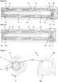
- Figure 1 shows a drug delivery device in the form of an injection pen.
- the device has a distal end (left end in Figure 1 ) and a proximal end (right end in Figure 1 ).
- the component parts of the drug delivery device are shown in Figure 2 .
- the drug delivery device comprises a body or housing 10, a cartridge holder 20, a lead screw (piston rod) 30, a drive sleeve 40, a nut 50, a dose indicator (number sleeve) 60, a button 70, a dial grip or dose selector 80, a torsion spring 90, a cartridge 100, a gauge element 110, a clutch plate 120, a clutch spring 130 and a bearing 140.
- a needle arrangement (not shown) with a needle hub and a needle cover may be provided as additional components, which can be exchanged as explained above. All components are located concentrically about a common principal axis I of the mechanism which is shown in Figure 3 .
- the housing 10 or body is a generally tubular element having a proximal end with an enlarged diameter.
- the housing 10 provides location for the liquid medication cartridge 100 and cartridge holder 20, windows 11a, 11b for viewing the dose number on the number sleeve 60 and the gauge element 110, and a feature on its external surface, e.g. a circumferential groove, to axially retain the dose selector 80.
- a flange-like or cylindrical inner wall 12 comprises an inner thread engaging the piston rod 30.
- the housing 10 further has at least one internal, axially orientated slot or the like for axially guiding the gauge element 110. In the embodiment shown in the Figures, the distal end is provided with an axially extending strip 13 partly overlapping cartridge holder 20.
- the Figures depict the housing 10 as a single housing component. However, the housing 10 could comprise two or more housing components which may be permanently attached to each other during assembly of the device.
- the cartridge holder 20 is located at the distal side of housing 10 and permanently attached thereto.
- the cartridge holder may be a transparent or translucent component which is tubular to receive cartridge 100.
- the distal end of cartridge holder 20 may be provided with means for attaching a needle arrangement.
- a removable cap (not shown) may be provided to fit over the cartridge holder 20 and may be retained via clip features on the housing 10.
- the piston rod 30 is rotationally constrained to the drive sleeve 40 via a splined interface. When rotated, the piston rod 30 is forced to move axially relative to the drive sleeve 40, through its threaded interface with the inner wall 12 of housing 10.
- the lead screw 30 is an elongate member with an outer thread 31 ( Figure 3 ) engaging the corresponding thread of the inner wall 12 of housing 10.
- the thread 31 may have a large lead-in, for example a wedge shape form, at its distal end to engage a corresponding housing thread form on the first rotation.
- the interface comprises at least one longitudinal groove or track and a corresponding protrusion or spline 45 of the driver 40.
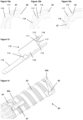
- the lead screw 30 is provided with an interface for clip attachment of the bearing 140.
- this interface comprises two clip arms 32 extending in the distal direction defining an insertion space between them for insertion of a bearing 140 interface.
- the interface may comprise only one single clip arm extending more than 180° about the longitudinal axis, or may comprise one or several clip arms 32.
- the clip arm(s) 32 may have a bent form with a recessed clip portion as shown in Figure 8 .
- the clip arm(s) form a cylindrical outer face having a diameter equal to or smaller than the outer diameter of the lead screw 30 at the base of the groove (flute base) of the outer thread 31.
- a concave contact surface 33 is provided between the clip arms 32 for abutment of a corresponding portion of bearing 140.
- the drive sleeve 40 is a hollow member surrounding the lead screw 30 and arranged within number sleeve 60. It extends from an interface with the clutch plate 120 to the contact with the clutch spring 130.
- the drive sleeve 40 is axially movable relative to the housing 10, the piston rod 30 and the number sleeve 60 in the distal direction against the bias of clutch spring 130 and in the opposite proximal direction under the bias of clutch spring 130.
- a further splined tooth interface with the number sleeve 60 is not engaged during dialling, but engages when the button 70 is pressed, preventing relative rotation between the drive sleeve 40 and number sleeve 60 during dispense.
- this interface comprises inwardly directed splines 61 on a flange 62 on the inner surface of the number sleeve 60 and a ring of radially extending outer splines 42 of drive sleeve 40.
- the corresponding splines 61, 42 are located on the number sleeve 60 and the drive sleeve 40, respectively, such that axial movement of the drive sleeve 40 relative to the (axially fixed) number sleeve 60 engages or disengages the splines to rotationally couple or decouple the drive sleeve 40 and the number sleeve 60.
- An interface of the drive sleeve 40 which is shown in Figure 19 comprises a ring of ratchet teeth 43 located at the proximal end face of drive sleeve 40 and a ring of corresponding ratchet teeth 121 of clutch plate 120.
- the driver 40 has a threaded section 44 providing a helical track for the nut 50 ( Figure 20 ).
- a last dose abutment or stop 46 is provided which may be the end of the thread 44 track or preferably a rotational hard stop for interaction with a corresponding last dose stop 51 of nut 50, thus limiting movement of the nut 50 on the thread 44.
- At least one longitudinal spline 45 engages a corresponding track of the lead screw 30.
- the drive sleeve is provided with a ramp 47 interacting with a clicker arm 67 when the drive sleeve 40 is in its distal position during dose dispensing, i.e. when button 70 is depressed.
- the last dose nut 50 is located between the number sleeve 60 and the drive sleeve 40. It is rotationally constrained to the number sleeve 60, via a splined interface (splines 52 on nut 50). It moves along a helical path relative to the drive sleeve 40, via a threaded interface (thread 44), when relative rotation occurs between the number sleeve 60 and drive sleeve 40 which is during dialling only. This is shown in Figure 20 . As an alternative, the nut 50 may be splined to the driver 40 and threaded to the number sleeve 60.
- the nut 50 is a full nut, but in alternative embodiments it may be a half nut, i.e. a component extending approximately 180° around the center axis of the device.
- a last dose stop 51 is provided engaging stop 46 of drive sleeve 40 when a dose is set corresponding to the remaining dispensable amount of medicament in the cartridge 100.
- the dose indicator or number sleeve 60 is a tubular element as shown in Figures 2 and 3 .
- the number sleeve 60 is rotated during dose setting (via dose selector 80) and dose correction and during dose dispensing by torsion spring 90. Together with gauge element 110 the number sleeve 60 defines a zero position ('at rest') and a maximum dose position. Thus, the number sleeve 60 may be seen as a dose setting member.
- the number sleeve 60 of the embodiment shown in the Figures comprises a number sleeve lower 60a which is rigidly fixed to a number sleeve upper 60b during assembly to form the number sleeve 60.
- Number sleeve lower 60a and number sleeve upper 60b are separate components only to simplify number sleeve 60 mould tooling and assembly.
- the number sleeve 60 may be a unitary component.
- the number sleeve 60 is constrained to the housing 10 by features towards the distal end to allow rotation but not translation.
- the number sleeve lower 60a is marked with a sequence of numbers, which are visible through the gauge element 110 and the openings 11a, 11b in the housing 10, to denote the dialled dose of medicament.
- the number sleeve lower 60a has a portion with an outer thread 63 engaging the gauge element 110. End stops 64, 65 are provided at the opposite ends of thread 63 to limit relative movement with respect to the gauge element 110.
- Clutch features which have the form of a ring of splines 66 in the embodiment of Figure 5 are provided inwardly directed on number sleeve upper 60b for engagement with splines 73 of the button 70 during dose setting and dose correction.
- a clicker arm 67 is provided on the outer surface of number sleeve 60 which interacts with the drive sleeve 40 and the gauge member 110 for generating a feedback signal.
- the number sleeve lower 60a is rotationally constrained to the nut 50 and to the clutch plate 120 via a splined interface comprising at least one longitudinal spline.
- An interface for attachment of the torsion spring 90 to the number sleeve lower 60a comprises large lead-ins and a groove feature 68 with a pocket 69 or anchor point for receiving a first coil or hook portion of the spring.
- the groove 68 has an end feature in the form of a ramp that is in interference with the hook portion 91 of the spring.
- the design of the groove 68 is such that the spring 90 may be received within the pocket 69 without interfering with the gauge element 110.
- the button 70 which forms the proximal end of the device is permanently splined to the dose selector 80.
- a central stem 71 extends distally from the proximal actuation face of the button 70.
- the stem 71 is provided with a flange 72 carrying the splines 73 for engagement with splines 66 of the number sleeve upper 60b ( Figure 5 ).
- splines 66, 73 Figure 5
- the button 70 has a discontinuous annular skirt with splines 74.
- splines 74 on the button 70 engage with splines on the housing 10 ( Figure 6 ), preventing rotation of the button 70 (and hence the dose selector 80) during dispense. These splines 74, 15 disengage when the button 70 is released, allowing a dose to be dialled. Further, a ring of ratchet teeth 75 is provided on the inner side of flange 72 ( Figure 9 ) for interaction with clutch plate 120.
- the dose selector 80 is axially constrained to the housing 10. It is rotationally constrained, via the splined interface, to the button 70. This splined interface which includes grooves interacting with spline features formed by the annular skirt of button 70 remains engaged irrespective of the dose button 70 axial positions.
- the dose selector 80 or dose dial grip is a sleeve-like component with a serrated outer skirt.
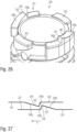
- the torsion spring 90 is attached at its distal end to the housing 10 and at the other end to the number sleeve 60.
- the torsion spring 90 is located inside the number sleeve 60 and surrounds a distal portion of the drive sleeve 40. As shown in Figure 16 , the spring has a hook 91 at one end for attachment on the number sleeve 60. A similar hook end 92 is provided at the opposite end for attachment on the housing 10.
- the torsion spring 90 is pre-wound upon assembly, such that it applies a torque to the number sleeve 60 when the mechanism is at zero units dialled. The action of rotating the dose selector 80, to set a dose, rotates the number sleeve 60 relative to the housing 10, and charges the torsion spring 90 further.
- the torsion spring 90 is formed from a helical wire with at least two different pitches.
- both ends are formed from 'closed' coils 93, i.e. the pitch equals the wire diameter and each coil contacts the adjacent coil.
- the central portion has 'open' coils 94, i.e. the coils do not contact each other.
- the cartridge 100 is received in cartridge holder 20 ( Figure 3 ).
- the cartridge 100 may be a glass ampoule having a moveable rubber bung 101 at its proximal end.
- the distal end of cartridge 100 is provided with a pierceable rubber seal which is held in place by a crimped annular metal band.
- the cartridge 100 is a standard 1,5 ml cartridge.
- the device is designed to be disposable in that the cartridge 100 cannot be replaced by the user or health care professional. However, a reusable variant of the device could be provided by making the cartridge holder 20 removable and allowing backwinding of the lead screw 30 and the resetting of nut 50.
- the gauge element 110 is constrained to prevent rotation but allow translation relative to the housing 10 via a splined interface.
- the gauge element 110 has a helical feature 111 on its inner surface which engages with the helical thread cut in the number sleeve 60 such that rotation of the number sleeve 60 causes axial translation of the gauge element 110.
- This helical feature on the gauge element 110 also creates stop abutments 112, 113 against the end of the helical cut in the number sleeve 60 to limit the minimum and maximum dose that can be set.
- the gauge element 110 has a generally plate or band like component having a central aperture 114 or window and two flanges 115, 116 extending on either side of the aperture.
- gauge element 110 has a cam 117 and a recess 118 ( Figures 11a - 12c ) interacting with the clicker arm 67 of the number sleeve 60 at the end of dose dispensing.
- the clutch plate 120 is a ring-like component.
- the clutch plate 120 is splined to the number sleeve 60 via splines 122. It is also coupled to the drive sleeve 40 via a ratchet interface (ratchet teeth 43, 121).
- the ratchet provides a detented position between the number sleeve 60 and drive sleeve 40 corresponding to each dose unit, and engages different ramped tooth angles during clockwise and anti-clockwise relative rotation.
- a clicker arm 123 is provided on the clutch plate 120 for interaction with ratchet features 75 of the button.
- the clutch spring 130 is a compression spring.
- the axial position of the drive sleeve 40, clutch plate 120 and button 70 is defined by the action of the clutch spring 130, which applies a force on the drive sleeve 40 in the proximal direction.
- This spring force is reacted via the drive sleeve 40, clutch plate 120, and button 70, and when 'at rest' it is further reacted through the dose selector 80 to the housing 10.
- the spring force ensures that the ratchet interface (ratchet teeth 43, 121) is always engaged. In the 'at rest' position, it also ensures that the button splines 73 are engaged with the number sleeve splines 66, and the drive sleeve teeth 41 are engaged with teeth 14 of the housing 10.
- the bearing 140 is axially constrained to the piston rod 30 and acts on the bung 101 within the liquid medicament cartridge. It is axially clipped to the lead screw 30, but free to rotate.
- the bearing 140 comprises a disc 141 having a stem 142 extending in the proximal direction.
- the stem 142 has at its proximal end a convex contact surface 143.
- a recessed portion 144 is provided on the stem 142.
- the curvature of the convex contact surface 143 and the concave contact surface 33 is chosen such that the contact diameter between the bearing 140 and lead screw 30 is small to minimize the frictional losses at this interface.
- the torsion spring 90 which has a number of pre-wound turns applied to it during assembly of the device, applies a torque to the number sleeve 60 and is prevented from rotating by the zero dose abutment 64, 113. It is also possible to 'back-wind' the mechanism slightly due to an offset between the zero dose stop 64, 113 and the angular offset of the drive sleeve 40 spline teeth. This has the effect of preventing possible weepage when a dose is dialled and the zero dose abutment is disengaged.
- the automated assembly of the torsion spring 90 into the number sleeve 60 can be achieved by incorporating large lead-ins and a groove feature to the number sleeve 60. As the torsion spring 90 is rotated during assembly, the hook end form 91 locates in the groove feature before engaging the anchor point in the number sleeve 60. To help to prevent the torsion spring 90 disengaging the anchor point 69 during subsequent assembly steps it is possible to create an interference between the torsion spring 90 and the number sleeve 60, or a one-way clip feature.
- a specific feature is the inclusion of a visual feedback feature in addition to the discrete dose number display typical on devices of this type.
- the distal end (flange 115) of the gauge element 110 creates a sliding scale through a small window 11a in the housing 10.
- the sliding scale could be formed using a separate component engaged with the number sleeve 60 on a different helical track.
- the gauge element 110 translates axially, the distance moved proportional to the magnitude of the dose set.
- This feature gives clear feedback to the user regarding the approximate size of the dose set.
- the dispense speed of an auto-injector mechanism may be higher than for a manual injector device, so it may not be possible to read the numerical dose display during dispense.
- the gauge feature provides feedback to the user during dispense regarding dispense progress without the need to read the dose number itself.
- the gauge display may be formed by an opaque element on the gauge element 110 revealing a contrasting coloured component underneath.
- the revealable element may be printed with coarse dose numbers or other indices to provide more precise resolution.
- the gauge display simulates a syringe action during dose set and dispense.
- the openings 11a, 11b in the housing 10 allow the user to view the gauge feature and number display as shown in Figures 17a and 17b .
- these openings 11a, 11b are covered by translucent windows. These windows may be separate components, but in this embodiment they are incorporated into the housing 10 using 'twin-shot' moulding technology. A first shot of translucent material forms the internal features and the windows 11a, 11b, and then a 'second shot' of opaque material forms the outer cover of the housing 10.
- the mechanism utilises a dose selector 80 with an increased diameter relative to the housing 10 which aids dialling although this is not a requirement of the mechanism.
- This feature is particularly useful (but not essential) for an auto-injector mechanism where a power supply is charged during dose setting and the torque required to turn the dose selector 80 may be higher than for a non-auto injector device.
- the drive sleeve 40 is prevented from rotating as the dose is set and the number sleeve 60 rotated, due to the engagement of its splined teeth 41 with teeth 14 of the housing 10. Relative rotation must therefore occur between the clutch plate 120 and drive sleeve 40 via the ratchet interface 43, 121.
- the user torque required to rotate the dose selector 80 is a sum of the torque required to wind up the torsion spring 90, and the torque required to overhaul the ratchet interface 43, 121.
- the clutch spring 130 is designed to provide an axial force to the ratchet interface 43, 121 and to bias the clutch plate 120 onto the drive sleeve 40. This axial load acts to maintain the ratchet teeth engagement of the clutch plate 120 and drive sleeve 40.
- the torque required to overhaul the ratchet 43, 121 in the dose set direction is a function of the axial load applied by the clutch spring 130, the clockwise ramp angle of the ratchet teeth 43, 121, the friction coefficient between the mating surfaces and the mean radius of the ratchet interface 43, 121.
- the number sleeve 60 rotates relative to the drive sleeve 40 by one ratchet tooth.
- the ratchet teeth 43, 121 re-engage into the next detented position.
- An audible click is generated by the ratchet re-engagement, and tactile feedback is given by the change in torque input required.
- Relative rotation of the number sleeve 60 and the drive sleeve 40 is allowed as splines 42, 61 are disengaged during dose setting. This relative rotation also causes the last dose nut 50 to travel along its threaded path, towards its last dose abutment on the drive sleeve 40.
- the torque necessary to overhaul the ratchet in the anti-clockwise direction is a function of the axial load applied by the clutch spring 130, the anti-clockwise ramp angle of the ratchet, the friction coefficient between the mating surfaces and the mean radius of the ratchet features.
- the torque necessary to overhaul the ratchet must be greater than the torque applied to the number sleeve 60 (and hence clutch plate 120) by the torsion spring 90.
- the ratchet ramp angle is therefore increased in the anti-clockwise direction to ensure this is the case whilst ensuring the dial-up torque is as low as possible.
- the user may now choose to increase the selected dose by continuing to rotate the dose selector 80 in the clockwise direction.
- the process of overhauling the ratchet interface 43, 121 between the number sleeve 60 and drive sleeve 40 is repeated for each dose increment. Additional energy is stored within the torsion spring 90 for each dose increment and audible and tactile feedback is provided for each increment dialled by the re-engagement of the ratchet teeth.
- the torque required to rotate the dose selector 80 increases as the torque required to wind up the torsion spring 90 increases.
- the torque required to overhaul the ratchet in the anti-clockwise direction must therefore be greater than the torque applied to the number sleeve 60 by the torsion spring 90 when the maximum dose has been reached.
- the number sleeve 60 engages with its maximum dose abutment 65 on the maximum dose abutment 112 of gauge element 110. This prevents further rotation of the number sleeve 60, clutch plate 120 and dose selector 80.
- the last dose nut 50 may contact its last dose abutment 51 with stop face 46 of the drive sleeve 40.
- the abutment prevents further relative rotation between the number sleeve 60 and the drive sleeve 40, and therefore limits the dose that can be selected.
- the position of the last dose nut 50 is determined by the total number of relative rotations between the number sleeve 60 and drive sleeve 40, which have occurred each time the user sets a dose.
- the user With the mechanism in a state in which a dose has been selected, the user is able to deselect any number of increments from this dose. Deselecting a dose is achieved by the user rotating the dose selector 80 anti-clockwise.
- the torque applied to the dose selector 80 by the user is sufficient, when combined with the torque applied by the torsion spring 90, to overhaul the ratchet interface 43, 121 between the clutch plate 120 and drive sleeve 40 in the anti-clockwise direction.
- anti-clockwise rotation occurs in the number sleeve 60 (via the clutch plate 120), which returns the number sleeve 60 towards the zero dose position, and unwinds the torsion spring 90.
- the relative rotation between the number sleeve 60 and drive sleeve 40 causes the last dose nut 50 to return along its helical path, away from the last dose abutment.
- the user With the mechanism in a state in which a dose has been selected, the user is able to activate the mechanism to commence delivery of a dose. Delivery of a dose is initiated by the user depressing the button 70 axially in the distal direction.
- buttons 70 and number sleeve 60 When the button 70 is depressed, splines between the button 70 and number sleeve 60 are disengaged, rotationally disconnecting the button 70 and dose selector 80 from the delivery mechanism, i.e. from number sleeve 60, gauge element 110 and torsion spring 90. Splines 74 on the button 70 engage with splines 15 on the housing 10, preventing rotation of the button 70 (and hence the dose selector 80) during dispense. As the button 70 is stationary during dispense, it can be used in the dispense clicker mechanism as shown in Figure 9 . A stop feature in the housing 10 limits axial travel of the button 70 and reacts any axial abuse loads applied by the user, reducing the risk of damaging internal components.
- the clutch plate 120 and drive sleeve 40 travel axially with the button 70. This engages the splined tooth interface 42, 61 between the drive sleeve 40 and number sleeve 60 as shown in Figures 7a (splines 42, 61 disengaged) and 7b (splines 42, 61 engaged), preventing relative rotation between the drive sleeve 40 and number sleeve 60 during dispense.
- the splined tooth interface 41, 14 between the drive sleeve 40 and the housing 10 disengages, so the drive sleeve 40 can now rotate and is driven by the torsion spring 90 via the number sleeve 60, and clutch plate 120.
- Rotation of the drive sleeve 40 causes the piston rod 30 to rotate due to their splined engagement, and the piston rod 30 then advances due to its threaded engagement to the housing 10.
- the number sleeve 60 rotation also causes the gauge element 110 to traverse axially back to its zero position whereby the zero dose abutment 64, 113 stops the mechanism.
- the bearing 140 is axially clipped to the piston rod 30, but free to rotate. Since the bearing 140 is in direct contact with the bung 101, it does not rotate as the piston rod 30 rotates and advances during dose dispense. As described above, the contact diameter between the bearing 140 and piston rod 30 is small to minimise the frictional losses at this interface.
- the design of the piston rod 30 and bearing 140 eliminates delicate clip features or large contact diameters present on previous concepts. This embodiment also allows the piston rod 30 to be assembled axially, from the proximal end and through the thread engagement to the housing 10, which simplifies assembly.
- Tactile feedback during dose dispense is provided via the compliant cantilever clicker arm 123 integrated into the clutch plate 120.
- This arm 123 interfaces radially with ratchet features 75 on the inner surface of the button 70, whereby the ratchet tooth spacing corresponds to the number sleeve 60 rotation required for a single increment dispense.
- the ratchet features 75 engage with the clicker arm 123 to produce an audible click with each dose increment delivered.
- the drive sleeve 40 and number sleeve 60 rotate together, so that no relative motion in the last dose nut 50 occurs.
- the last dose nut 50 therefore travels axially relative to the drive sleeve 40 during dialling only.
- the user may release the button 70, which will re-engage the spline teeth 14, 41 between the drive sleeve 40 and housing 10.
- the mechanism is now returned to the 'at rest' condition.
- additional audible feedback is provided in the form of a 'click', distinct from the 'clicks' provided during dispense, to inform the user that the device has returned to its zero position via the interaction of the clicker arm 67 on the number sleeve 60 with the ramp 47 on the drive sleeve 40 and the cam 117 and the recess 118 on the gauge element 110.
- This embodiment allows feedback to only be created at the end of dose delivery and not created if the device is dialled back to, or away from, the zero position.
- Figure 11a shows the position of the click features when the device is in the 'at rest' condition, with zero units dialled and the button 70 not depressed. It can be seen that the cam feature 117 on the gauge element 110 does not contact the clicker arm 67 on the number sleeve 60 when the button 70 is in the 'at rest' condition, so during storage or dialling the clicker arm 67 is not deflected.
- the gauge element 110 translates in the proximal direction, so the cam 117 is no longer aligned axially with the clicker arm 67.
- the ramp 47 on the drive sleeve 40 pushes the clicker arm 67 radially outwards.
- the gauge element 110 translates back in the distal direction, and towards the end of dose delivery, the clicker arm 67 contacts the cam 117 on the gauge element 110.
- the cam 117 and clicker arm 67 will be in contact at the start of the dose.
- Figures 11b to 12c show the component interactions. After dose delivery, the button 70 is released and the end of dose mechanism returns to its 'at rest' position.
- FIG 11b a dose is dialled and approximately one full dial turn is applied to number sleeve 60.
- Gauge element 110 is axially translated away from zero unit position, so that cam 117 is no longer aligned axially with clicker arm 67.
- Figure 11c shows the start of dispensing, when button 70 is depressed to initiate dose dispense and which causes the drive sleeve 70 to translate axially. Ramp 47 on the drive sleeve 40 pushes clicker arm 67 radially out and into radial alignment with cam 117 on the gauge element 110.
- Figure 12a shows the mechanism at the end of dose dispensing with approximately 4 units remaining.
- the gauge element 110 returns axially towards its zero unit position, so that cam 117 aligns axially with clicker arm 67.
- Rotation of number sleeve 60 causes clicker arm 67 to contact cam 117 such that clicker arm 67 is pushed radially inwards.
- With approximately 2 units remaining the number sleeve 60 rotates further and clicker arm 67 follows the profile of cam 117 ( Figure 12b ).
- This radial deflection 'charges' clicker arm 67 storing elastic energy.
- dispensing is completed as the number sleeve 60 reaches its zero unit rotational position.
- the clicker arm 67 drops off the sharp edge of cam 117 into recess 118.
- Elastic energy is released causing clicker arm 67 to spring radially outwards to contact cam 117 and create a distinct 'click'.
- the lead screw 30 advances by a fixed displacement for each revolution of the drive sleeve 40.
- the rate of displacement may vary.
- the lead screw 30 may advance a large displacement per revolution to dispense a first amount of medicament from the cartridge 100 and then a smaller displacement per revolution to dispense the rest of the cartridge 100. This is advantageous, as it can compensate for the fact that the first dose dispensed from the cartridge 100 often has a lower volume than other doses, for a given displacement of the mechanism.
- Figure 22 shows three embodiments with the threads 16 of the housing 10 and the threads 31 of the lead screw 30 projected around the circumference.
- Arrow R indicates the direction of revolution of the lead screw 30 with respect to housing 10 for all three views.
- View (a) shows the principal embodiment, where the pitch is equal on the housing 10 and lead screw 30, so the lead screw 30 advances a fixed amount for every revolution of the drive sleeve 40.
- the first turn of thread 31 on the lead screw 30 has a large pitch, and the other turns have a small pitch.
- the lead screw 30 displacement depends on the large pitch of the first turn of thread 31 on the lead screw 30, so it displaces a large amount per revolution.
- the lead screw 30 displacement depends on the smaller pitch of the lead screw thread 31, so it displaces a smaller amount.
- the housing 10 thread 16 has a larger pitch than the lead screw 30.
- the lead screw 30 displacement depends on the pitch of the housing thread 16, so it displaces a large amount per revolution.
- the lead screw 30 displacement depends on the pitch of the lead screw thread 31, so it displaces a smaller amount.
- the drug delivery device comprises a dose setting mechanism for setting a minimum dose size.
- a dose setting mechanism should ensure that the user cannot dispense less medicament than required.
- the drug delivery device comprises a number sleeve 60 which rotates in one direction, which is the dose setting direction, during dose setting.
- the number sleeve 60 rotates in the reverse direction during dispensing or correction of the set dose.
- the gauge element 110 engages the thread 63 on the number sleeve 60, resulting in an axial movement in the dose setting direction during setting and in the reverse direction during dispensing or correction.
- the ratchet mechanism 200 comprises a circular-shaped ratchet member 220 and a circular-shaped counter ratchet member 240.
- the ratchet member comprises a sleeve-like shape and the counter ratchet member also comprises a tubular or sleeve-like shape.
- the ratchet member 220 comprises a ratchet surface 221 provided with a number of ratchet features 222, 224 and with a number of intermediate sections 223, 225 located between the ratchet features 222, 224.
- the ratchet features 222, 224 are identically shaped. They may also be of different shape.
- Each one of the ratchet features 222, 224 comprises a ratchet tooth 226.
- the ratchet tooth 226 comprises a non-symmetric shape along a circumferential direction.
- the ratchet tooth 226 comprises a first ramped section 226a and a second ramped section 226b.
- the first ramped section 226a is rather steep and the second ramped section 226b is comparatively shallow.
- the ramp angle of the first ramped section 226a is larger than the ramp angle of the second ramped section 226b.
- the ratchet surface 221 is of annular shape. It may be located on the bottom of an annular groove 230 at a longitudinal end face of the ratchet member 220.
- the ratchet member 220 comprises a tubular-shaped stem section 231 and a circular-shaped flange section 232 located at a longitudinal end of the stem section 231.
- the radial extension of the flange section 232, hence the diameter of the flange section 232 is larger than the radial extent or the diameter of the stem section 231.
- protrusions 233 protruding radially outwardly from the flange section 232. These protrusions are configured to form a splined interface with the number sleeve 60 of the injection device as described above in connection with Figures 1-22 .
- the ratchet member 220 replaces the clutch plate 120 of the injection device as described in connection with Figures 1-22 .
- any features, benefits and mechanical interactions as described above in connection with the clutch plate 120 equally apply to the ratchet member 220, 320 as described below in connection with the Figures 26-30 .
- the counter ratchet member 240, 340 as described below and as shown in the Figures 23-30 is equivalent to the driver 40 as described above in connection with the Figures 1-22 .
- the driver 40 is effectively replaced by the counter ratchet member 240, 340. Any features, benefits and mechanical interaction as described above in connection with the driver 40 equally apply to the counter ratchet member 240, 340.
- the ratchet surface 221 forms a distal end face of the ratchet member 220.
- the counter ratchet member 240 also comprises a counter ratchet surface 241 facing towards the ratchet surface 221.
- the ratchet surface 221 and the counter ratchet surface 241 are and remain in axial abutment through the action of the clutch spring 130.
- the counter ratchet surface 241 faces in proximal direction 3.
- the ratchet surface 221 faces in distal direction 2.
- each one of the counter ratchet features 242, 244 comprises a counter ratchet tooth 246.
- each one of the counter ratchet teeth 246 comprises a first ramped section 246a and a second ramped section 246b. Also here, the first ramped section 246a is steeper than the second ramped section 246b.
- the ratchet member 220 is subject to a rotation along a second sense of rotation 6 relative to the housing 10 and/or relative to the counter ratchet member 240, e.g. in clockwise direction so as to increase the size of a dose to be set and to be expelled by the injection device 1.
- Rotation of the dose selector 80 along the second sense of rotation 6 leads to a respective rotation of the ratchet member 240 along the second sense of rotation 6 and hence to a respective rotation of the dose indicator 60 along the second sense of rotation 6.
- the torsion spring 90 operably engaged with the dose indicator 60 is biased further and tends to rotate the dose indicator 60 along the opposite sense of rotation, hence along the first sense of rotation 5.
- the ratchet mechanism 200 formed by the mutual engagement of the ratchet surface 221 and the counter ratchet surface 241 provides a kind of a slip clutch that only engages at a few distinct angular or rotational states of the ratchet member 220 relative to the counter ratchet member 240. These distinct rotational states of the ratchet member are defined by the geometry and the position of the ratchet features 222, 224 and the correspondingly shaped counter ratchet features 242, 244.
- ratchet features 222, 224 on the ratchet surface 221 and there are provided only two correspondingly shaped counter ratchet features 242, 244 on the counter ratchet surface 241.
- the ratchet features 222, 224 and the counter ratchet features 242, 244 are configured to engage with their first ramped sections 226a, 246a as the ratchet member 220 is rotated along the first sense of rotation 5 relative to the counter ratchet member, hence as the ratchet member 220 is rotated under the action of the depleting torsion spring 90.
- a further rotation of the ratchet member 220 relative to the counter ratchet member 240 along the first sense of rotation 5 is only possible if a torque above at least a first torque M1 is applied to the ratchet member 220 relative to the counter ratchet member 240.
- the ramp angle of the first ramped sections 226a, 246a may be as large as 90° with regard to the plane of the ratchet surface 221 or counter ratchet surface 241. In this case, the first torque M1 will be larger than or equal to a mechanical destruction level of at least one of the ratchet member 220 and the counter ratchet member 240.
- the mutual engagement of the at least one ratchet feature 222, 224 of the ratchet member 220 with at least one counter ratchet features 242, 244 of the counter ratchet member 240 will define a stop position for the rotation of the ratchet member 220 under the action of the depleting torsion spring 90.
- ratchet mechanism only provides a rather small resistance against the action of the depleting torsion spring 90.
- the ratchet member 220 can be rotated relative to the counter ratchet member 240 along the first sense of rotation 5 if a torque equal to or above a predefined second torque M2 is present between the ratchet member 220 and the counter ratchet member 240.
- the magnitude of the second torque M2 may even be equal to zero or may be almost equal to zero.
- each one of the ratchet features and counter ratchet features of one of the ratchet surface and the counter ratchet surface is exclusively engaged with an intermediate section of the other one of the ratchet surface and the counter ratchet surface the ratchet member can be rotated along the first sense of rotation 5 under the action of the depleting torsion spring 90 until at least one of the ratchet features 222, 224 engages with at least one of the counter ratchet features 242, 244.
- the angular or circumferential size of the intermediate sections 223, 225, 243, 245 is larger, even much larger, than the circumferential extension of the ratchet features 222, 224 and the counter ratchet features 242, 244.
- the two ratchet features 222, 224 of the ratchet surface 222 are equidistantly spaced on the ratchet surface 221.
- the counter ratchet features 242, 244 are also equally or equidistantly spaced on the counter ratchet surface 241.
- a holding torque or stop torque to be transferred between the ratchet member 220 and the counter ratchet member 240 can thus be split among the pairs of inter-engaging ratchet features 222, 224 and counter ratchet features 242, 244.
- the robustness of the ratchet mechanism 200 can be increased and a susceptibility of the ratchet features 222, 224 and the counter ratchet features 242, 244 against mechanical damage or breakage can be reduced.
- the circumferential extension of the second ramped section 226b, 246b compared to the circumferential extension of the first ramped section 226a, 246a is comparatively large.
- the ramp angle of the second ramped section 226b, 246b is substantially smaller than the ramp angle of the first ramped section 226a, 246a.
- this provides a rather smooth and easy rotation of the ratchet member 220 relative to the counter ratchet member 240 along the second sense of rotation 6.
- the comparatively shallow ramp angles of the second ramped sections 226b, 246b only provide a comparatively low mechanical resistance.
- the comparatively large circumferential extension of the second ramped sections 226b, 246b increases the mechanical stability of the teeth 226, 246 of the ratchet features 222, 224 and the counter ratchet features 242, 244.
- the ratchet member 220 may engage with its first ramped section 226a with a correspondingly shaped first ramped section 246a at a comparatively large angular velocity.
- the comparatively large circumferential extension of the second ramped sections 226b, 246b increases the mechanical rigidity and stability of the respective teeth specifically when the comparatively steep first ramped sections 226a, 246a mutually engage or mutually abut in circumferential or tangential direction.
- a further example of a ratchet mechanism 300 of the invention in accordance to the Figures 28-30 is substantially equivalent to the ratchet mechanism 200 as described above in connection with Figures 23-27 .
- the intermediate sections 323, 325, 343, 345 located between the ratchet features 322, 324 and the counter ratchet features 343, 345 are not plane shaped but comprise at least one or numerous intermediate ratchet features 332, 352.
- the ratchet surface 321 of the ratchet member 320 comprises two ratchet features 322, 324 each comprising a ratchet tooth 326 with a first ramped section 326a and a second ramped section 326b.
- the counter ratchet surface 341 comprises two substantially identically shaped counter ratchet features 342, 344 each comprising a counter ratchet tooth 346 having a first ramped section 346a and a second ramped section 346b.
- the ratchet features 322, 324 are equidistantly arranged along the circumference of the annular-shaped ratchet surface 321.
- the intermediate sections 323, 325 located between the two ratchet features 322, 324 comprise numerous intermediate ratchet features 332.
- Each one of the intermediate ratchet features 332 comprises an intermediate ratchet tooth 336 having a first ramped section 336a and a second ramped section 336b.
- the first and the second ramped sections 336a, 336b are located at opposite side edges of the intermediate ratchet tooth 336.
- the longitudinal or axial height of the intermediate teeth 336 is smaller than a height of the ratchet teeth 326.
- a counter ratchet feature 342, 344 is out of engagement from any of the ratchet features 322, 324 and is in engagement with at least one intermediate ratchet member 332 the ratchet member 320 can be rotated along the first sense of rotation 5 as soon as a torque above a third torque M3 is applied between the ratchet member 320 and the counter ratchet member 340.
- this third torque M3 is smaller than a driving torque provided by the torsion spring 90.
- the mutual engagement of the intermediate ratchet features 332 with a counter ratchet feature 342, 344 provides a braking effect to the torsion spring induced rotation of the ratchet member 320 along the first sense of rotation 5.
- This engagement further provides an audible and/or haptic feedback to the user as a dose is set, e.g. when the ratchet member 320 is subject to a rotation relative to the counter ratchet member 340 along the second sense of rotation.
- the ratchet surface 321 and the counter ratchet surface 341 are provided with numerous equidistantly and regularly arranged intermediate ratchet features 332, 352.
- the intermediate ratchet features 352 may be identically shaped or may correspond to the intermediate ratchet feature 332.
- the intermediate ratchet features 352 may each comprise an intermediate ratchet tooth 356 having a first ramped section 356a and a second ramped section 356b.
- the axial or longitudinal extension or height of the intermediate ratchet teeth 356 is smaller than the axial or longitudinal extension or height of the counter ratchet features 342, 344.
- the total number of intermediate ratchet features 332 and ratchet features 322, 324 may be equal to the number of ratchet features or clicker features of other ratchet mechanisms or clicker mechanisms provided in the injection device.
- the angular or circumferential width of the intermediate ratchet features 332 and the ratchet features 322, 324 may be substantially identical. A full revolution of the ratchet member 340 may be thus divided into a number of discrete steps of equal step size.
- the granularity or the step size, hence the total number of intermediate ratchet features 332 and ratchet features 322, 324 may be equal to the number of splines 66 of the dose indicator 60 or may be equal to the number of splines or ratchet teeth 75 of the button 70.
Landscapes
- Health & Medical Sciences (AREA)
- Vascular Medicine (AREA)
- Engineering & Computer Science (AREA)
- Anesthesiology (AREA)
- Biomedical Technology (AREA)
- Heart & Thoracic Surgery (AREA)
- Hematology (AREA)
- Life Sciences & Earth Sciences (AREA)
- Animal Behavior & Ethology (AREA)
- General Health & Medical Sciences (AREA)
- Public Health (AREA)
- Veterinary Medicine (AREA)
- Infusion, Injection, And Reservoir Apparatuses (AREA)
Claims (15)
- Ratschenmechanismus (200; 300), der für eine Injektionsvorrichtung (1) ausgestaltet ist, wobei der Ratschenmechanismus umfasst:- ein Gehäuse (10),- ein kreisförmiges Ratschenglied (220; 320), das insbesondere bezogen auf das Gehäuse (10) drehbar gelagert ist, wobei das Ratschenglied (220; 320) umfasst:wobei das Drehen des Ratschengliedes (220; 320) bezogen auf das Gegenratschenglied (240; 340) entlang der ersten Drehrichtung (5) erfordert:- eine Ratschenoberfläche (221; 321),- eine Reihe von Ratschenmerkmalen (222, 224; 322, 324) auf der Ratschenoberfläche (221; 321) und- eine Reihe von Zwischenabschnitten (223, 225; 323, 325) auf der Ratschenoberfläche (221; 321), die sich zwischen den Ratschenmerkmalen (222, 224; 322, 324) erstrecken,- ein kreisförmiges Gegenratschenglied (240; 340), das koaxial zu dem Ratschenglied (220; 320) angeordnet und bezogen auf das Ratschenglied (220; 320) mindestens entlang einer ersten Drehrichtung (5) drehbar ist, insbesondere bezogen auf das Gehäuse (10) drehbar gelagert ist, wobei das Gegenratschenglied (240; 340) umfasst:- eine Gegenratschenoberfläche (241; 341),- eine Reihe von Gegenratschenmerkmalen (242, 244; 342, 344) auf der Gegenratschenoberfläche (241; 341) und- eine Reihe von Zwischenabschnitten (243, 245; 343, 345) auf der Gegenratschenoberfläche (241; 341), die sich zwischen den Gegenratschenmerkmalen (242, 244; 342, 344) erstrecken,- das Aufbringen von mindestens einem ersten Drehmoment (M1) zwischen dem Ratschenglied (220; 320) und dem Gegenratschenglied (240; 340), wenn mindestens eins der Ratschenmerkmale (222, 224; 322, 324) mit mindestens einem der Gegenratschenmerkmale (242, 244; 342, 344) im Eingriff ist, und- das Aufbringen von mindestens einem zweiten Drehmoment (M2), das kleiner ist als das erste Drehmoment (M1), zwischen dem Ratschenglied (220; 320) und dem Gegenratschenglied (240; 340), wenn jedes der Ratschenmerkmale (222, 224; 322, 324) mit einem beliebigen der Gegenratschenmerkmale (242, 244; 342, 344) außer Eingriff ist, undi) wenn mindestens ein Ratschenmerkmal (222, 224; 322, 324) mit einem Zwischenabschnitt (243, 245; 343, 345) der Gegenratschenoberfläche (241; 341) im Eingriff ist und/oderii) wenn mindestens eins der Gegenratschenmerkmale (242, 244; 342, 344) mit einem Zwischenabschnitt (223, 225; 323, 325) der Ratschenoberfläche (241; 341) im Eingriff ist.
- Ratschenmechanismus nach Anspruch 1, wobei das Ratschenglied (220; 320) zwei oder mehr Ratschenmerkmale (222, 224; 322, 324) umfasst, die gleichmäßig auf der Ratschenoberfläche (221; 321) beabstandet sind.
- Ratschenmechanismus nach Anspruch 1 oder 2, wobei das Gegenratschenglied (240; 340) zwei oder mehr Gegenratschenmerkmale (242, 244; 342, 344) umfasst, die gleichmäßig auf der Gegenratschenoberfläche (241; 341) beabstandet sind.
- Ratschenmechanismus nach einem der vorhergehenden Ansprüche, wobei eine Reihe von Ratschenmerkmalen (222, 224; 322, 324) auf der Ratschenoberfläche (221; 321) einer Reihe von Gegenratschenmerkmalen (242, 244; 342, 344) auf der Gegenratschenoberfläche (241; 341) gleicht.
- Ratschenmechanismus nach einem der vorhergehenden Ansprüche 1 bis 3, wobei eine Reihe von Ratschenmerkmalen (222, 224; 322, 324) auf der Ratschenoberfläche (221; 321) größer oder kleiner ist als eine Reihe von Gegenratschenmerkmalen (242, 244; 342, 344) auf der Gegenratschenoberfläche (241; 341).
- Ratschenmechanismus nach einem der vorhergehenden Ansprüche, wobei mindestens eines der Ratschenmerkmale (222, 224; 322, 324) und der Gegenratschenmerkmale (242, 244; 342, 344) einen Zahn (226, 246; 326, 346) umfasst, der von der Ratschenoberfläche (221; 321) oder der Gegenratschenoberfläche (241; 341) vorspringt, wobei der Zahn (226, 246; 326, 346) einen ersten rampenförmigen Abschnitt (226a, 246a; 326a, 346a) und einen zweiten rampenförmigen Abschnitt (226b, 246b; 326b, 346b) gegenüber dem ersten rampenförmigen Abschnitt (226a, 246a; 326a, 346a) umfasst, wobei sich ein Rampenwinkel des ersten rampenförmigen Abschnitts (226a, 246a; 326a, 346a) von einem Rampenwinkel des zweiten rampenförmigen Abschnitts (226b, 246b; 326b, 346b) unterscheidet.
- Ratschenmechanismus nach Anspruch 6, wobei eine Umfangserstreckung des zweiten rampenförmigen Abschnitts (226b, 246b; 326b, 346b) mindestens 2 oder 3 Mal größer ist als eine Umfangserstreckung des ersten rampenförmigen Abschnitts (226a, 246a; 326a, 346a).
- Ratschenmechanismus nach einem der vorhergehenden Ansprüche, wobei die Zwischenabschnitte (223, 225, 243, 245) von mindestens einer der Ratschenoberfläche (221) und der Gegenratschenoberfläche (241) eben geformt und frei von Vorsprüngen oder Aussparungen sind.
- Ratschenmechanismus nach einem der vorhergehenden Ansprüche, wobei mindestens eine der Ratschenoberfläche (321) und der Gegenratschenoberfläche (341) mindestens ein Zwischenratschenmerkmal (332, 352) umfasst, wobei das Drehen des Ratschengliedes (320) bezogen auf das Gegenratschenglied (340) entlang der ersten Drehrichtung (5) erfordert:- das Aufbringen von mindestens einem dritten Drehmoment (M3) zwischen dem Ratschenglied (320) und dem Gegenratschenglied (340) entlang der ersten Drehrichtung (5), wenn mindestens eins der Zwischenratschenmerkmale (332, 352) mit mindestens einem der Ratschenmerkmale (322, 324) oder der Gegenratschenmerkmale (342, 344) im Eingriff ist, wobei das dritte Drehmoment (M3) größer ist als das zweite Drehmoment (M2) und wobei das dritte Drehmoment (M3) kleiner ist als das erste Drehmoment (M1) .
- Ratschenmechanismus nach Anspruch 9, wobei eine Höhe des mindestens einen Zwischenratschenmerkmals (332, 352) kleiner ist als eine Höhe von mindestens einem der Ratschenmerkmale (222, 224; 322, 324) und der Gegenratschenmerkmale (242, 244; 342, 344).
- Ratschenmechanismus nach Anspruch 9 oder 10, wobei das mindestens eine Zwischenratschenmerkmal (332, 352) einen Zahn (336, 356) umfasst, der von dem Zwischenabschnitt (323, 325, 343, 345) vorspringt, wobei der Zahn (336, 356) einen ersten rampenförmigen Abschnitt (336a, 356a) und einen zweiten rampenförmigen Abschnitt (336b, 356b) gegenüber dem ersten rampenförmigen Abschnitt (336a, 356a) umfasst und wobei ein Rampenwinkel des ersten rampenförmigen Abschnitts (336a, 356a) des mindestens einen Zwischenratschenmerkmals (332, 352) kleiner ist als ein Rampenwinkel eines ersten rampenförmigen Abschnitts (326a, 346a) eines Zahns (326, 346) von mindestens einem des Ratschenmerkmals (322, 324) oder des Gegenratschenmerkmals (342, 344).
- Ratschenmechanismus nach einem der vorhergehenden Ansprüche, wobei das Ratschenglied (220; 320) entlang einer zweiten Drehrichtung (6) gegen die Wirkung einer Torsionsfeder (90) drehbar ist und wobei die Torsionsfeder (90) dazu ausgestaltet ist, ein Antriebsdrehmoment auf das Ratschenglied (220; 320) aufzubringen, wobei das Antriebsdrehmoment kleiner ist als das erste Drehmoment (M1) und wobei das Antriebsdrehmoment größer ist als das zweite Drehmoment (M2) .
- Ratschenmechanismus nach Anspruch 9 und 12, wobei das Antriebsdrehmoment größer ist als das dritte Drehmoment (M3).
- Injektionsvorrichtung zum Ausstoßen einer Reihe von voreingestellten oder vom Benutzer wählbaren Dosen eines Medikaments, wobei die Injektionsvorrichtung umfasst:- ein längserstrecktes Gehäuse (10), das sich entlang einer Längsachse (I) erstreckt und dazu ausgestaltet ist, eine Kartusche (100) zu beherbergen, die das Medikament enthält und einen Stopfen (101) aufweist, der ein proximales Ende der Kartusche (100) abdichtet,- eine Kolbenstange (30), die dazu ausgestaltet ist, gegen den Stopfen (101) entlang der Längsachse (I) in eine distale Richtung bezogen auf das Gehäuse (10) zu drängen,- einen Dosiswähler (80), der zum Einstellen einer Dosis bezogen auf das Gehäuse (10) drehbar ist, und- einen Ratschenmechanismus (200; 300) nach einem der vorhergehenden Ansprüche, wobei das Ratschenglied (220; 320) mindestens während des Einstellens der Dosis drehbar an dem Dosiswähler (80) verriegelt wird und wobei das Gegenratschenglied (240; 340) mindestens zum Ausstoßen der Dosis drehbar mit mindestens einem von der Kolbenstange (30) und dem Gehäuse (10) in Eingriff gelangbar oder drehbar verriegelbar ist.
- Injektionsvorrichtung nach Anspruch 14, wobei das Gegenratschenglied (240; 340) mindestens während des Ausstoßens der Dosis und zum Drängen der Kolbenstange gegen den Stopfen (101) bezogen auf das Gehäuse (10) drehbar ist.
Applications Claiming Priority (2)
| Application Number | Priority Date | Filing Date | Title |
|---|---|---|---|
| EP18305262 | 2018-03-13 | ||
| PCT/EP2019/055949 WO2019175073A1 (en) | 2018-03-13 | 2019-03-11 | Ratchet mechanism and injection device |
Publications (2)
| Publication Number | Publication Date |
|---|---|
| EP3765130A1 EP3765130A1 (de) | 2021-01-20 |
| EP3765130B1 true EP3765130B1 (de) | 2024-06-05 |
Family
ID=61691907
Family Applications (1)
| Application Number | Title | Priority Date | Filing Date |
|---|---|---|---|
| EP19709495.6A Active EP3765130B1 (de) | 2018-03-13 | 2019-03-11 | Ratschenmechanismus und einspritzvorrichtung |
Country Status (5)
| Country | Link |
|---|---|
| US (1) | US11638784B2 (de) |
| EP (1) | EP3765130B1 (de) |
| JP (1) | JP7467351B2 (de) |
| DK (1) | DK3765130T3 (de) |
| WO (1) | WO2019175073A1 (de) |
Families Citing this family (2)
| Publication number | Priority date | Publication date | Assignee | Title |
|---|---|---|---|---|
| US10435226B2 (en) | 2016-12-27 | 2019-10-08 | Doselogix, Llc | Dosing dispenser system |
| EP4181987A1 (de) | 2020-07-15 | 2023-05-24 | Novo Nordisk A/S | Wiederverwendbare injektionsvorrichtung mit torsionsfederantrieb |
Family Cites Families (5)
| Publication number | Priority date | Publication date | Assignee | Title |
|---|---|---|---|---|
| US9132239B2 (en) | 2008-10-24 | 2015-09-15 | Novo Nordisk A/S | Dial-down mechanism for wind-up pen |
| EP2707063B1 (de) * | 2011-05-12 | 2019-06-26 | SHL Medical AG | Medizinische abgabevorrichtung mit dosierungsneueinstellung |
| TW201707737A (zh) | 2015-06-03 | 2017-03-01 | 賽諾菲阿凡提斯德意志有限公司 | 藥物輸送裝置(一) |
| WO2018041899A1 (en) * | 2016-08-31 | 2018-03-08 | Novo Nordisk A/S | Drug delivery device with over-torque protection mechanism |
| WO2018041988A1 (de) | 2016-09-01 | 2018-03-08 | Leica Microsystems Cms Gmbh | Mikroskop zur betrachtung einzeln beleuchteter schiefer ebenen mit einem mikrolinsen-array |
-
2019
- 2019-03-11 EP EP19709495.6A patent/EP3765130B1/de active Active
- 2019-03-11 JP JP2020548766A patent/JP7467351B2/ja active Active
- 2019-03-11 DK DK19709495.6T patent/DK3765130T3/da active
- 2019-03-11 WO PCT/EP2019/055949 patent/WO2019175073A1/en not_active Ceased
- 2019-03-11 US US16/977,941 patent/US11638784B2/en active Active
Also Published As
| Publication number | Publication date |
|---|---|
| JP7467351B2 (ja) | 2024-04-15 |
| US20210069422A1 (en) | 2021-03-11 |
| JP2021515661A (ja) | 2021-06-24 |
| EP3765130A1 (de) | 2021-01-20 |
| US11638784B2 (en) | 2023-05-02 |
| DK3765130T3 (da) | 2024-08-26 |
| WO2019175073A1 (en) | 2019-09-19 |
Similar Documents
| Publication | Publication Date | Title |
|---|---|---|
| US10226582B2 (en) | Drug delivery device | |
| US11185633B2 (en) | Spring arrangement and drug delivery device herewith | |
| US20170119971A1 (en) | Clicker arrangement and drug delivery device herewith | |
| US10471218B2 (en) | Drug delivery device | |
| US10744270B2 (en) | Dose setting mechanism and drug delivery device with ratchet mechanism | |
| EP3164180A1 (de) | Arzneimittelabgabevorrichtung mit gewindegehäuse und kolben und verfahren zur herstellung davon | |
| US20170259006A1 (en) | Mechanism for setting a maximum dose of a medicament for a variable dose drug delivery device | |
| US10220154B2 (en) | Drug delivery device | |
| EP3164181A1 (de) | Injektionsvorrichtung mit druckfeder zum einrasten von ratschenelementen zur vorspannung eines betätigungsknopfes und zur vorspannung eines verriegelungselements in einem dosiseinstellungsmodus | |
| WO2016055626A1 (en) | Dosing assembly for drug delivery device with different leads and multi-start thread section | |
| EP3765130B1 (de) | Ratschenmechanismus und einspritzvorrichtung | |
| US20220096755A1 (en) | Assembly for a Drug Delivery Device, Drug Delivery Device and Method for Producing a Drug Delivery Device | |
| HK1233562A1 (en) | Drug delivery device | |
| HK1233562B (en) | Drug delivery device | |
| HK1239592A1 (en) | Dose setting mechanism and drug delivery device with ratchet mechanism | |
| HK1239592B (en) | Dose setting mechanism and drug delivery device with ratchet mechanism |
Legal Events
| Date | Code | Title | Description |
|---|---|---|---|
| STAA | Information on the status of an ep patent application or granted ep patent |
Free format text: STATUS: UNKNOWN |
|
| STAA | Information on the status of an ep patent application or granted ep patent |
Free format text: STATUS: THE INTERNATIONAL PUBLICATION HAS BEEN MADE |
|
| PUAI | Public reference made under article 153(3) epc to a published international application that has entered the european phase |
Free format text: ORIGINAL CODE: 0009012 |
|
| STAA | Information on the status of an ep patent application or granted ep patent |
Free format text: STATUS: REQUEST FOR EXAMINATION WAS MADE |
|
| 17P | Request for examination filed |
Effective date: 20201013 |
|
| AK | Designated contracting states |
Kind code of ref document: A1 Designated state(s): AL AT BE BG CH CY CZ DE DK EE ES FI FR GB GR HR HU IE IS IT LI LT LU LV MC MK MT NL NO PL PT RO RS SE SI SK SM TR |
|
| AX | Request for extension of the european patent |
Extension state: BA ME |
|
| DAV | Request for validation of the european patent (deleted) | ||
| DAX | Request for extension of the european patent (deleted) | ||
| GRAP | Despatch of communication of intention to grant a patent |
Free format text: ORIGINAL CODE: EPIDOSNIGR1 |
|
| STAA | Information on the status of an ep patent application or granted ep patent |
Free format text: STATUS: GRANT OF PATENT IS INTENDED |
|
| INTG | Intention to grant announced |
Effective date: 20231120 |
|
| GRAJ | Information related to disapproval of communication of intention to grant by the applicant or resumption of examination proceedings by the epo deleted |
Free format text: ORIGINAL CODE: EPIDOSDIGR1 |
|
| STAA | Information on the status of an ep patent application or granted ep patent |
Free format text: STATUS: REQUEST FOR EXAMINATION WAS MADE |
|
| GRAP | Despatch of communication of intention to grant a patent |
Free format text: ORIGINAL CODE: EPIDOSNIGR1 |
|
| STAA | Information on the status of an ep patent application or granted ep patent |
Free format text: STATUS: GRANT OF PATENT IS INTENDED |
|
| INTC | Intention to grant announced (deleted) | ||
| INTG | Intention to grant announced |
Effective date: 20240402 |
|
| GRAS | Grant fee paid |
Free format text: ORIGINAL CODE: EPIDOSNIGR3 |
|
| GRAA | (expected) grant |
Free format text: ORIGINAL CODE: 0009210 |
|
| STAA | Information on the status of an ep patent application or granted ep patent |
Free format text: STATUS: THE PATENT HAS BEEN GRANTED |
|
| AK | Designated contracting states |
Kind code of ref document: B1 Designated state(s): AL AT BE BG CH CY CZ DE DK EE ES FI FR GB GR HR HU IE IS IT LI LT LU LV MC MK MT NL NO PL PT RO RS SE SI SK SM TR |
|
| REG | Reference to a national code |
Ref country code: CH Ref legal event code: EP |
|
| REG | Reference to a national code |
Ref country code: DE Ref legal event code: R096 Ref document number: 602019053200 Country of ref document: DE |
|
| REG | Reference to a national code |
Ref country code: IE Ref legal event code: FG4D |
|
| REG | Reference to a national code |
Ref country code: DK Ref legal event code: T3 Effective date: 20240822 |
|
| REG | Reference to a national code |
Ref country code: LT Ref legal event code: MG9D |
|
| PG25 | Lapsed in a contracting state [announced via postgrant information from national office to epo] |
Ref country code: BG Free format text: LAPSE BECAUSE OF FAILURE TO SUBMIT A TRANSLATION OF THE DESCRIPTION OR TO PAY THE FEE WITHIN THE PRESCRIBED TIME-LIMIT Effective date: 20240605 |
|
| REG | Reference to a national code |
Ref country code: NL Ref legal event code: MP Effective date: 20240605 |
|
| PG25 | Lapsed in a contracting state [announced via postgrant information from national office to epo] |
Ref country code: FI Free format text: LAPSE BECAUSE OF FAILURE TO SUBMIT A TRANSLATION OF THE DESCRIPTION OR TO PAY THE FEE WITHIN THE PRESCRIBED TIME-LIMIT Effective date: 20240605 Ref country code: HR Free format text: LAPSE BECAUSE OF FAILURE TO SUBMIT A TRANSLATION OF THE DESCRIPTION OR TO PAY THE FEE WITHIN THE PRESCRIBED TIME-LIMIT Effective date: 20240605 |
|
| PG25 | Lapsed in a contracting state [announced via postgrant information from national office to epo] |
Ref country code: GR Free format text: LAPSE BECAUSE OF FAILURE TO SUBMIT A TRANSLATION OF THE DESCRIPTION OR TO PAY THE FEE WITHIN THE PRESCRIBED TIME-LIMIT Effective date: 20240906 |
|
| PG25 | Lapsed in a contracting state [announced via postgrant information from national office to epo] |
Ref country code: ES Free format text: LAPSE BECAUSE OF FAILURE TO SUBMIT A TRANSLATION OF THE DESCRIPTION OR TO PAY THE FEE WITHIN THE PRESCRIBED TIME-LIMIT Effective date: 20240605 |
|
| PG25 | Lapsed in a contracting state [announced via postgrant information from national office to epo] |
Ref country code: LV Free format text: LAPSE BECAUSE OF FAILURE TO SUBMIT A TRANSLATION OF THE DESCRIPTION OR TO PAY THE FEE WITHIN THE PRESCRIBED TIME-LIMIT Effective date: 20240605 |
|
| PG25 | Lapsed in a contracting state [announced via postgrant information from national office to epo] |
Ref country code: NO Free format text: LAPSE BECAUSE OF FAILURE TO SUBMIT A TRANSLATION OF THE DESCRIPTION OR TO PAY THE FEE WITHIN THE PRESCRIBED TIME-LIMIT Effective date: 20240905 Ref country code: LV Free format text: LAPSE BECAUSE OF FAILURE TO SUBMIT A TRANSLATION OF THE DESCRIPTION OR TO PAY THE FEE WITHIN THE PRESCRIBED TIME-LIMIT Effective date: 20240605 Ref country code: HR Free format text: LAPSE BECAUSE OF FAILURE TO SUBMIT A TRANSLATION OF THE DESCRIPTION OR TO PAY THE FEE WITHIN THE PRESCRIBED TIME-LIMIT Effective date: 20240605 Ref country code: GR Free format text: LAPSE BECAUSE OF FAILURE TO SUBMIT A TRANSLATION OF THE DESCRIPTION OR TO PAY THE FEE WITHIN THE PRESCRIBED TIME-LIMIT Effective date: 20240906 Ref country code: FI Free format text: LAPSE BECAUSE OF FAILURE TO SUBMIT A TRANSLATION OF THE DESCRIPTION OR TO PAY THE FEE WITHIN THE PRESCRIBED TIME-LIMIT Effective date: 20240605 Ref country code: ES Free format text: LAPSE BECAUSE OF FAILURE TO SUBMIT A TRANSLATION OF THE DESCRIPTION OR TO PAY THE FEE WITHIN THE PRESCRIBED TIME-LIMIT Effective date: 20240605 Ref country code: BG Free format text: LAPSE BECAUSE OF FAILURE TO SUBMIT A TRANSLATION OF THE DESCRIPTION OR TO PAY THE FEE WITHIN THE PRESCRIBED TIME-LIMIT Effective date: 20240605 Ref country code: RS Free format text: LAPSE BECAUSE OF FAILURE TO SUBMIT A TRANSLATION OF THE DESCRIPTION OR TO PAY THE FEE WITHIN THE PRESCRIBED TIME-LIMIT Effective date: 20240905 |
|
| PG25 | Lapsed in a contracting state [announced via postgrant information from national office to epo] |
Ref country code: NL Free format text: LAPSE BECAUSE OF FAILURE TO SUBMIT A TRANSLATION OF THE DESCRIPTION OR TO PAY THE FEE WITHIN THE PRESCRIBED TIME-LIMIT Effective date: 20240605 |
|
| REG | Reference to a national code |
Ref country code: AT Ref legal event code: MK05 Ref document number: 1691987 Country of ref document: AT Kind code of ref document: T Effective date: 20240605 |
|
| PG25 | Lapsed in a contracting state [announced via postgrant information from national office to epo] |
Ref country code: NL Free format text: LAPSE BECAUSE OF FAILURE TO SUBMIT A TRANSLATION OF THE DESCRIPTION OR TO PAY THE FEE WITHIN THE PRESCRIBED TIME-LIMIT Effective date: 20240605 |
|
| PG25 | Lapsed in a contracting state [announced via postgrant information from national office to epo] |
Ref country code: PT Free format text: LAPSE BECAUSE OF FAILURE TO SUBMIT A TRANSLATION OF THE DESCRIPTION OR TO PAY THE FEE WITHIN THE PRESCRIBED TIME-LIMIT Effective date: 20241007 |
|
| PG25 | Lapsed in a contracting state [announced via postgrant information from national office to epo] |
Ref country code: PT Free format text: LAPSE BECAUSE OF FAILURE TO SUBMIT A TRANSLATION OF THE DESCRIPTION OR TO PAY THE FEE WITHIN THE PRESCRIBED TIME-LIMIT Effective date: 20241007 |
|
| PG25 | Lapsed in a contracting state [announced via postgrant information from national office to epo] |
Ref country code: PL Free format text: LAPSE BECAUSE OF FAILURE TO SUBMIT A TRANSLATION OF THE DESCRIPTION OR TO PAY THE FEE WITHIN THE PRESCRIBED TIME-LIMIT Effective date: 20240605 |
|
| PG25 | Lapsed in a contracting state [announced via postgrant information from national office to epo] |
Ref country code: EE Free format text: LAPSE BECAUSE OF FAILURE TO SUBMIT A TRANSLATION OF THE DESCRIPTION OR TO PAY THE FEE WITHIN THE PRESCRIBED TIME-LIMIT Effective date: 20240605 |
|
| PG25 | Lapsed in a contracting state [announced via postgrant information from national office to epo] |
Ref country code: AT Free format text: LAPSE BECAUSE OF FAILURE TO SUBMIT A TRANSLATION OF THE DESCRIPTION OR TO PAY THE FEE WITHIN THE PRESCRIBED TIME-LIMIT Effective date: 20240605 Ref country code: IS Free format text: LAPSE BECAUSE OF FAILURE TO SUBMIT A TRANSLATION OF THE DESCRIPTION OR TO PAY THE FEE WITHIN THE PRESCRIBED TIME-LIMIT Effective date: 20241005 |
|
| PG25 | Lapsed in a contracting state [announced via postgrant information from national office to epo] |
Ref country code: CZ Free format text: LAPSE BECAUSE OF FAILURE TO SUBMIT A TRANSLATION OF THE DESCRIPTION OR TO PAY THE FEE WITHIN THE PRESCRIBED TIME-LIMIT Effective date: 20240605 |
|
| PG25 | Lapsed in a contracting state [announced via postgrant information from national office to epo] |
Ref country code: SK Free format text: LAPSE BECAUSE OF FAILURE TO SUBMIT A TRANSLATION OF THE DESCRIPTION OR TO PAY THE FEE WITHIN THE PRESCRIBED TIME-LIMIT Effective date: 20240605 Ref country code: RO Free format text: LAPSE BECAUSE OF FAILURE TO SUBMIT A TRANSLATION OF THE DESCRIPTION OR TO PAY THE FEE WITHIN THE PRESCRIBED TIME-LIMIT Effective date: 20240605 |
|
| PG25 | Lapsed in a contracting state [announced via postgrant information from national office to epo] |
Ref country code: SM Free format text: LAPSE BECAUSE OF FAILURE TO SUBMIT A TRANSLATION OF THE DESCRIPTION OR TO PAY THE FEE WITHIN THE PRESCRIBED TIME-LIMIT Effective date: 20240605 |
|
| PG25 | Lapsed in a contracting state [announced via postgrant information from national office to epo] |
Ref country code: SM Free format text: LAPSE BECAUSE OF FAILURE TO SUBMIT A TRANSLATION OF THE DESCRIPTION OR TO PAY THE FEE WITHIN THE PRESCRIBED TIME-LIMIT Effective date: 20240605 Ref country code: SK Free format text: LAPSE BECAUSE OF FAILURE TO SUBMIT A TRANSLATION OF THE DESCRIPTION OR TO PAY THE FEE WITHIN THE PRESCRIBED TIME-LIMIT Effective date: 20240605 Ref country code: RO Free format text: LAPSE BECAUSE OF FAILURE TO SUBMIT A TRANSLATION OF THE DESCRIPTION OR TO PAY THE FEE WITHIN THE PRESCRIBED TIME-LIMIT Effective date: 20240605 Ref country code: PL Free format text: LAPSE BECAUSE OF FAILURE TO SUBMIT A TRANSLATION OF THE DESCRIPTION OR TO PAY THE FEE WITHIN THE PRESCRIBED TIME-LIMIT Effective date: 20240605 Ref country code: IS Free format text: LAPSE BECAUSE OF FAILURE TO SUBMIT A TRANSLATION OF THE DESCRIPTION OR TO PAY THE FEE WITHIN THE PRESCRIBED TIME-LIMIT Effective date: 20241005 Ref country code: EE Free format text: LAPSE BECAUSE OF FAILURE TO SUBMIT A TRANSLATION OF THE DESCRIPTION OR TO PAY THE FEE WITHIN THE PRESCRIBED TIME-LIMIT Effective date: 20240605 Ref country code: CZ Free format text: LAPSE BECAUSE OF FAILURE TO SUBMIT A TRANSLATION OF THE DESCRIPTION OR TO PAY THE FEE WITHIN THE PRESCRIBED TIME-LIMIT Effective date: 20240605 Ref country code: AT Free format text: LAPSE BECAUSE OF FAILURE TO SUBMIT A TRANSLATION OF THE DESCRIPTION OR TO PAY THE FEE WITHIN THE PRESCRIBED TIME-LIMIT Effective date: 20240605 |
|
| PG25 | Lapsed in a contracting state [announced via postgrant information from national office to epo] |
Ref country code: IT Free format text: LAPSE BECAUSE OF FAILURE TO SUBMIT A TRANSLATION OF THE DESCRIPTION OR TO PAY THE FEE WITHIN THE PRESCRIBED TIME-LIMIT Effective date: 20240605 |
|
| REG | Reference to a national code |
Ref country code: DE Ref legal event code: R097 Ref document number: 602019053200 Country of ref document: DE |
|
| PGFP | Annual fee paid to national office [announced via postgrant information from national office to epo] |
Ref country code: DE Payment date: 20241231 Year of fee payment: 7 |
|
| PLBE | No opposition filed within time limit |
Free format text: ORIGINAL CODE: 0009261 |
|
| STAA | Information on the status of an ep patent application or granted ep patent |
Free format text: STATUS: NO OPPOSITION FILED WITHIN TIME LIMIT |
|
| PGFP | Annual fee paid to national office [announced via postgrant information from national office to epo] |
Ref country code: DK Payment date: 20250317 Year of fee payment: 7 |
|
| PGFP | Annual fee paid to national office [announced via postgrant information from national office to epo] |
Ref country code: GB Payment date: 20250102 Year of fee payment: 7 |
|
| 26N | No opposition filed |
Effective date: 20250306 |
|
| PGFP | Annual fee paid to national office [announced via postgrant information from national office to epo] |
Ref country code: CH Payment date: 20250401 Year of fee payment: 7 |
|
| PG25 | Lapsed in a contracting state [announced via postgrant information from national office to epo] |
Ref country code: SE Free format text: LAPSE BECAUSE OF FAILURE TO SUBMIT A TRANSLATION OF THE DESCRIPTION OR TO PAY THE FEE WITHIN THE PRESCRIBED TIME-LIMIT Effective date: 20240605 |
|
| PG25 | Lapsed in a contracting state [announced via postgrant information from national office to epo] |
Ref country code: MC Free format text: LAPSE BECAUSE OF FAILURE TO SUBMIT A TRANSLATION OF THE DESCRIPTION OR TO PAY THE FEE WITHIN THE PRESCRIBED TIME-LIMIT Effective date: 20240605 |
|
| PG25 | Lapsed in a contracting state [announced via postgrant information from national office to epo] |
Ref country code: LU Free format text: LAPSE BECAUSE OF NON-PAYMENT OF DUE FEES Effective date: 20250311 |
|
| REG | Reference to a national code |
Ref country code: BE Ref legal event code: MM Effective date: 20250331 |
|
| PGFP | Annual fee paid to national office [announced via postgrant information from national office to epo] |
Ref country code: FR Payment date: 20251231 Year of fee payment: 8 |
|
| PG25 | Lapsed in a contracting state [announced via postgrant information from national office to epo] |
Ref country code: BE Free format text: LAPSE BECAUSE OF NON-PAYMENT OF DUE FEES Effective date: 20250331 |
|
| PG25 | Lapsed in a contracting state [announced via postgrant information from national office to epo] |
Ref country code: IE Free format text: LAPSE BECAUSE OF NON-PAYMENT OF DUE FEES Effective date: 20250311 |