EP3764919B1 - Apparatus for mitral valve chord repair - Google Patents
Apparatus for mitral valve chord repair Download PDFInfo
- Publication number
- EP3764919B1 EP3764919B1 EP19766750.4A EP19766750A EP3764919B1 EP 3764919 B1 EP3764919 B1 EP 3764919B1 EP 19766750 A EP19766750 A EP 19766750A EP 3764919 B1 EP3764919 B1 EP 3764919B1
- Authority
- EP
- European Patent Office
- Prior art keywords
- anchor
- leaflet
- suture
- catheter
- deployment system
- Prior art date
- Legal status (The legal status is an assumption and is not a legal conclusion. Google has not performed a legal analysis and makes no representation as to the accuracy of the status listed.)
- Active
Links
Images







Classifications
-
- A—HUMAN NECESSITIES
- A61—MEDICAL OR VETERINARY SCIENCE; HYGIENE
- A61B—DIAGNOSIS; SURGERY; IDENTIFICATION
- A61B17/00—Surgical instruments, devices or methods
- A61B17/04—Surgical instruments, devices or methods for suturing wounds; Holders or packages for needles or suture materials
- A61B17/0401—Suture anchors, buttons or pledgets, i.e. means for attaching sutures to bone, cartilage or soft tissue; Instruments for applying or removing suture anchors
-
- A—HUMAN NECESSITIES
- A61—MEDICAL OR VETERINARY SCIENCE; HYGIENE
- A61B—DIAGNOSIS; SURGERY; IDENTIFICATION
- A61B17/00—Surgical instruments, devices or methods
- A61B17/04—Surgical instruments, devices or methods for suturing wounds; Holders or packages for needles or suture materials
-
- A—HUMAN NECESSITIES
- A61—MEDICAL OR VETERINARY SCIENCE; HYGIENE
- A61B—DIAGNOSIS; SURGERY; IDENTIFICATION
- A61B17/00—Surgical instruments, devices or methods
- A61B17/04—Surgical instruments, devices or methods for suturing wounds; Holders or packages for needles or suture materials
- A61B17/0467—Instruments for cutting sutures
-
- A—HUMAN NECESSITIES
- A61—MEDICAL OR VETERINARY SCIENCE; HYGIENE
- A61B—DIAGNOSIS; SURGERY; IDENTIFICATION
- A61B17/00—Surgical instruments, devices or methods
- A61B17/04—Surgical instruments, devices or methods for suturing wounds; Holders or packages for needles or suture materials
- A61B17/0469—Suturing instruments for use in minimally invasive surgery, e.g. endoscopic surgery
-
- A—HUMAN NECESSITIES
- A61—MEDICAL OR VETERINARY SCIENCE; HYGIENE
- A61B—DIAGNOSIS; SURGERY; IDENTIFICATION
- A61B17/00—Surgical instruments, devices or methods
- A61B17/04—Surgical instruments, devices or methods for suturing wounds; Holders or packages for needles or suture materials
- A61B17/0485—Devices or means, e.g. loops, for capturing the suture thread and threading it through an opening of a suturing instrument or needle eyelet
-
- A—HUMAN NECESSITIES
- A61—MEDICAL OR VETERINARY SCIENCE; HYGIENE
- A61B—DIAGNOSIS; SURGERY; IDENTIFICATION
- A61B17/00—Surgical instruments, devices or methods
- A61B17/04—Surgical instruments, devices or methods for suturing wounds; Holders or packages for needles or suture materials
- A61B17/0487—Suture clamps, clips or locks, e.g. for replacing suture knots; Instruments for applying or removing suture clamps, clips or locks
-
- A—HUMAN NECESSITIES
- A61—MEDICAL OR VETERINARY SCIENCE; HYGIENE
- A61B—DIAGNOSIS; SURGERY; IDENTIFICATION
- A61B17/00—Surgical instruments, devices or methods
- A61B17/04—Surgical instruments, devices or methods for suturing wounds; Holders or packages for needles or suture materials
- A61B17/06—Needles ; Sutures; Needle-suture combinations; Holders or packages for needles or suture materials
- A61B17/06004—Means for attaching suture to needle
-
- A—HUMAN NECESSITIES
- A61—MEDICAL OR VETERINARY SCIENCE; HYGIENE
- A61F—FILTERS IMPLANTABLE INTO BLOOD VESSELS; PROSTHESES; DEVICES PROVIDING PATENCY TO, OR PREVENTING COLLAPSING OF, TUBULAR STRUCTURES OF THE BODY, e.g. STENTS; ORTHOPAEDIC, NURSING OR CONTRACEPTIVE DEVICES; FOMENTATION; TREATMENT OR PROTECTION OF EYES OR EARS; BANDAGES, DRESSINGS OR ABSORBENT PADS; FIRST-AID KITS
- A61F2/00—Filters implantable into blood vessels; Prostheses, i.e. artificial substitutes or replacements for parts of the body; Appliances for connecting them with the body; Devices providing patency to, or preventing collapsing of, tubular structures of the body, e.g. stents
-
- A—HUMAN NECESSITIES
- A61—MEDICAL OR VETERINARY SCIENCE; HYGIENE
- A61F—FILTERS IMPLANTABLE INTO BLOOD VESSELS; PROSTHESES; DEVICES PROVIDING PATENCY TO, OR PREVENTING COLLAPSING OF, TUBULAR STRUCTURES OF THE BODY, e.g. STENTS; ORTHOPAEDIC, NURSING OR CONTRACEPTIVE DEVICES; FOMENTATION; TREATMENT OR PROTECTION OF EYES OR EARS; BANDAGES, DRESSINGS OR ABSORBENT PADS; FIRST-AID KITS
- A61F2/00—Filters implantable into blood vessels; Prostheses, i.e. artificial substitutes or replacements for parts of the body; Appliances for connecting them with the body; Devices providing patency to, or preventing collapsing of, tubular structures of the body, e.g. stents
- A61F2/02—Prostheses implantable into the body
-
- A—HUMAN NECESSITIES
- A61—MEDICAL OR VETERINARY SCIENCE; HYGIENE
- A61F—FILTERS IMPLANTABLE INTO BLOOD VESSELS; PROSTHESES; DEVICES PROVIDING PATENCY TO, OR PREVENTING COLLAPSING OF, TUBULAR STRUCTURES OF THE BODY, e.g. STENTS; ORTHOPAEDIC, NURSING OR CONTRACEPTIVE DEVICES; FOMENTATION; TREATMENT OR PROTECTION OF EYES OR EARS; BANDAGES, DRESSINGS OR ABSORBENT PADS; FIRST-AID KITS
- A61F2/00—Filters implantable into blood vessels; Prostheses, i.e. artificial substitutes or replacements for parts of the body; Appliances for connecting them with the body; Devices providing patency to, or preventing collapsing of, tubular structures of the body, e.g. stents
- A61F2/02—Prostheses implantable into the body
- A61F2/24—Heart valves ; Vascular valves, e.g. venous valves; Heart implants, e.g. passive devices for improving the function of the native valve or the heart muscle; Transmyocardial revascularisation [TMR] devices; Valves implantable in the body
- A61F2/2442—Annuloplasty rings or inserts for correcting the valve shape; Implants for improving the function of a native heart valve
- A61F2/2454—Means for preventing inversion of the valve leaflets, e.g. chordae tendineae prostheses
-
- A—HUMAN NECESSITIES
- A61—MEDICAL OR VETERINARY SCIENCE; HYGIENE
- A61F—FILTERS IMPLANTABLE INTO BLOOD VESSELS; PROSTHESES; DEVICES PROVIDING PATENCY TO, OR PREVENTING COLLAPSING OF, TUBULAR STRUCTURES OF THE BODY, e.g. STENTS; ORTHOPAEDIC, NURSING OR CONTRACEPTIVE DEVICES; FOMENTATION; TREATMENT OR PROTECTION OF EYES OR EARS; BANDAGES, DRESSINGS OR ABSORBENT PADS; FIRST-AID KITS
- A61F2/00—Filters implantable into blood vessels; Prostheses, i.e. artificial substitutes or replacements for parts of the body; Appliances for connecting them with the body; Devices providing patency to, or preventing collapsing of, tubular structures of the body, e.g. stents
- A61F2/02—Prostheses implantable into the body
- A61F2/24—Heart valves ; Vascular valves, e.g. venous valves; Heart implants, e.g. passive devices for improving the function of the native valve or the heart muscle; Transmyocardial revascularisation [TMR] devices; Valves implantable in the body
- A61F2/2442—Annuloplasty rings or inserts for correcting the valve shape; Implants for improving the function of a native heart valve
- A61F2/2454—Means for preventing inversion of the valve leaflets, e.g. chordae tendineae prostheses
- A61F2/2457—Chordae tendineae prostheses
-
- A—HUMAN NECESSITIES
- A61—MEDICAL OR VETERINARY SCIENCE; HYGIENE
- A61F—FILTERS IMPLANTABLE INTO BLOOD VESSELS; PROSTHESES; DEVICES PROVIDING PATENCY TO, OR PREVENTING COLLAPSING OF, TUBULAR STRUCTURES OF THE BODY, e.g. STENTS; ORTHOPAEDIC, NURSING OR CONTRACEPTIVE DEVICES; FOMENTATION; TREATMENT OR PROTECTION OF EYES OR EARS; BANDAGES, DRESSINGS OR ABSORBENT PADS; FIRST-AID KITS
- A61F2/00—Filters implantable into blood vessels; Prostheses, i.e. artificial substitutes or replacements for parts of the body; Appliances for connecting them with the body; Devices providing patency to, or preventing collapsing of, tubular structures of the body, e.g. stents
- A61F2/02—Prostheses implantable into the body
- A61F2/24—Heart valves ; Vascular valves, e.g. venous valves; Heart implants, e.g. passive devices for improving the function of the native valve or the heart muscle; Transmyocardial revascularisation [TMR] devices; Valves implantable in the body
- A61F2/2442—Annuloplasty rings or inserts for correcting the valve shape; Implants for improving the function of a native heart valve
- A61F2/2466—Delivery devices therefor
-
- A—HUMAN NECESSITIES
- A61—MEDICAL OR VETERINARY SCIENCE; HYGIENE
- A61B—DIAGNOSIS; SURGERY; IDENTIFICATION
- A61B17/00—Surgical instruments, devices or methods
- A61B17/00234—Surgical instruments, devices or methods for minimally invasive surgery
- A61B2017/00238—Type of minimally invasive operation
- A61B2017/00243—Type of minimally invasive operation cardiac
-
- A—HUMAN NECESSITIES
- A61—MEDICAL OR VETERINARY SCIENCE; HYGIENE
- A61B—DIAGNOSIS; SURGERY; IDENTIFICATION
- A61B17/00—Surgical instruments, devices or methods
- A61B2017/00743—Type of operation; Specification of treatment sites
- A61B2017/00778—Operations on blood vessels
- A61B2017/00783—Valvuloplasty
-
- A—HUMAN NECESSITIES
- A61—MEDICAL OR VETERINARY SCIENCE; HYGIENE
- A61B—DIAGNOSIS; SURGERY; IDENTIFICATION
- A61B17/00—Surgical instruments, devices or methods
- A61B17/04—Surgical instruments, devices or methods for suturing wounds; Holders or packages for needles or suture materials
- A61B17/0401—Suture anchors, buttons or pledgets, i.e. means for attaching sutures to bone, cartilage or soft tissue; Instruments for applying or removing suture anchors
- A61B2017/0406—Pledgets
-
- A—HUMAN NECESSITIES
- A61—MEDICAL OR VETERINARY SCIENCE; HYGIENE
- A61B—DIAGNOSIS; SURGERY; IDENTIFICATION
- A61B17/00—Surgical instruments, devices or methods
- A61B17/04—Surgical instruments, devices or methods for suturing wounds; Holders or packages for needles or suture materials
- A61B17/0401—Suture anchors, buttons or pledgets, i.e. means for attaching sutures to bone, cartilage or soft tissue; Instruments for applying or removing suture anchors
- A61B2017/0409—Instruments for applying suture anchors
-
- A—HUMAN NECESSITIES
- A61—MEDICAL OR VETERINARY SCIENCE; HYGIENE
- A61B—DIAGNOSIS; SURGERY; IDENTIFICATION
- A61B17/00—Surgical instruments, devices or methods
- A61B17/04—Surgical instruments, devices or methods for suturing wounds; Holders or packages for needles or suture materials
- A61B17/0401—Suture anchors, buttons or pledgets, i.e. means for attaching sutures to bone, cartilage or soft tissue; Instruments for applying or removing suture anchors
- A61B2017/0417—T-fasteners
-
- A—HUMAN NECESSITIES
- A61—MEDICAL OR VETERINARY SCIENCE; HYGIENE
- A61B—DIAGNOSIS; SURGERY; IDENTIFICATION
- A61B17/00—Surgical instruments, devices or methods
- A61B17/04—Surgical instruments, devices or methods for suturing wounds; Holders or packages for needles or suture materials
- A61B17/0401—Suture anchors, buttons or pledgets, i.e. means for attaching sutures to bone, cartilage or soft tissue; Instruments for applying or removing suture anchors
- A61B2017/044—Suture anchors, buttons or pledgets, i.e. means for attaching sutures to bone, cartilage or soft tissue; Instruments for applying or removing suture anchors with a threaded shaft, e.g. screws
- A61B2017/0441—Suture anchors, buttons or pledgets, i.e. means for attaching sutures to bone, cartilage or soft tissue; Instruments for applying or removing suture anchors with a threaded shaft, e.g. screws the shaft being a rigid coil or spiral
-
- A—HUMAN NECESSITIES
- A61—MEDICAL OR VETERINARY SCIENCE; HYGIENE
- A61B—DIAGNOSIS; SURGERY; IDENTIFICATION
- A61B17/00—Surgical instruments, devices or methods
- A61B17/04—Surgical instruments, devices or methods for suturing wounds; Holders or packages for needles or suture materials
- A61B17/0401—Suture anchors, buttons or pledgets, i.e. means for attaching sutures to bone, cartilage or soft tissue; Instruments for applying or removing suture anchors
- A61B2017/0464—Suture anchors, buttons or pledgets, i.e. means for attaching sutures to bone, cartilage or soft tissue; Instruments for applying or removing suture anchors for soft tissue
-
- A—HUMAN NECESSITIES
- A61—MEDICAL OR VETERINARY SCIENCE; HYGIENE
- A61B—DIAGNOSIS; SURGERY; IDENTIFICATION
- A61B17/00—Surgical instruments, devices or methods
- A61B17/04—Surgical instruments, devices or methods for suturing wounds; Holders or packages for needles or suture materials
- A61B17/0487—Suture clamps, clips or locks, e.g. for replacing suture knots; Instruments for applying or removing suture clamps, clips or locks
- A61B2017/0488—Instruments for applying suture clamps, clips or locks
-
- A—HUMAN NECESSITIES
- A61—MEDICAL OR VETERINARY SCIENCE; HYGIENE
- A61B—DIAGNOSIS; SURGERY; IDENTIFICATION
- A61B17/00—Surgical instruments, devices or methods
- A61B17/04—Surgical instruments, devices or methods for suturing wounds; Holders or packages for needles or suture materials
- A61B2017/0496—Surgical instruments, devices or methods for suturing wounds; Holders or packages for needles or suture materials for tensioning sutures
-
- A—HUMAN NECESSITIES
- A61—MEDICAL OR VETERINARY SCIENCE; HYGIENE
- A61B—DIAGNOSIS; SURGERY; IDENTIFICATION
- A61B17/00—Surgical instruments, devices or methods
- A61B17/04—Surgical instruments, devices or methods for suturing wounds; Holders or packages for needles or suture materials
- A61B17/06—Needles ; Sutures; Needle-suture combinations; Holders or packages for needles or suture materials
- A61B2017/06052—Needle-suture combinations in which a suture is extending inside a hollow tubular needle, e.g. over the entire length of the needle
-
- A—HUMAN NECESSITIES
- A61—MEDICAL OR VETERINARY SCIENCE; HYGIENE
- A61B—DIAGNOSIS; SURGERY; IDENTIFICATION
- A61B90/00—Instruments, implements or accessories specially adapted for surgery or diagnosis and not covered by any of the groups A61B1/00 - A61B50/00, e.g. for luxation treatment or for protecting wound edges
- A61B90/39—Markers, e.g. radio-opaque or breast lesions markers
- A61B2090/3966—Radiopaque markers visible in an X-ray image
-
- A—HUMAN NECESSITIES
- A61—MEDICAL OR VETERINARY SCIENCE; HYGIENE
- A61F—FILTERS IMPLANTABLE INTO BLOOD VESSELS; PROSTHESES; DEVICES PROVIDING PATENCY TO, OR PREVENTING COLLAPSING OF, TUBULAR STRUCTURES OF THE BODY, e.g. STENTS; ORTHOPAEDIC, NURSING OR CONTRACEPTIVE DEVICES; FOMENTATION; TREATMENT OR PROTECTION OF EYES OR EARS; BANDAGES, DRESSINGS OR ABSORBENT PADS; FIRST-AID KITS
- A61F2220/00—Fixations or connections for prostheses classified in groups A61F2/00 - A61F2/26 or A61F2/82 or A61F9/00 or A61F11/00 or subgroups thereof
- A61F2220/0008—Fixation appliances for connecting prostheses to the body
- A61F2220/0016—Fixation appliances for connecting prostheses to the body with sharp anchoring protrusions, e.g. barbs, pins, spikes
-
- A—HUMAN NECESSITIES
- A61—MEDICAL OR VETERINARY SCIENCE; HYGIENE
- A61F—FILTERS IMPLANTABLE INTO BLOOD VESSELS; PROSTHESES; DEVICES PROVIDING PATENCY TO, OR PREVENTING COLLAPSING OF, TUBULAR STRUCTURES OF THE BODY, e.g. STENTS; ORTHOPAEDIC, NURSING OR CONTRACEPTIVE DEVICES; FOMENTATION; TREATMENT OR PROTECTION OF EYES OR EARS; BANDAGES, DRESSINGS OR ABSORBENT PADS; FIRST-AID KITS
- A61F2220/00—Fixations or connections for prostheses classified in groups A61F2/00 - A61F2/26 or A61F2/82 or A61F9/00 or A61F11/00 or subgroups thereof
- A61F2220/0025—Connections or couplings between prosthetic parts, e.g. between modular parts; Connecting elements
- A61F2220/0075—Connections or couplings between prosthetic parts, e.g. between modular parts; Connecting elements sutured, ligatured or stitched, retained or tied with a rope, string, thread, wire or cable
Definitions
- the present disclosure relates to mitral valve repair or replacement and more generally to methods and methods and devices for mitral valve reshaping, repair and/or replacement of mitral chords to restore proper functioning of the mitral valve from a state of mitral valve regurgitation.
- the heart includes four heart valves, which allow blood to pass through the four chambers of the heart in one direction.
- the four valves are the tricuspid, mitral, pulmonary and aortic valves.
- the four chambers are the right and left atria (upper chambers) and right and left ventricle (lower chambers).
- the mitral valve is formed by two leaflets, which are known as the anterior leaflet and the posterior leaflet, which open and close in response to pressure placed on the leaflets by the pumping of the heart.
- MR mitral valve regurgitation
- problems include mitral valve regurgitation (MR), in which the mitral valve leaflets do not close properly, which can cause leakage of the mitral valve. Severe mitral regurgitation can adversely affect cardiac function and compromise a patient's quality of life and life-span.
- mitral valve regurgitation Several techniques have been developed, for correcting mitral valve regurgitation. These include heart transplant, valve replacement or repair, chordae tendinea shortening or replacement and mitral annular repair also known as annuloplasty, depending upon the stage and underlying etiology.
- chordae tendinea replacement or repair As it relates to chordae tendinea replacement or repair, certain surgical and trans apical approaches have been proposed. Despite those efforts, however, there remains a need for a transvascular approach for chordae tendinea replacement or repair, to reduce or eliminate MR.
- a leaflet anchor deployment system comprising: a catheter having a proximal end and a distal end; a leaflet anchor positioned on a distal end of the catheter; and a needle advanceable through the leaflet anchor, the needle releasably carrying a radially enlargeable leaflet anchor preloaded therein and having a suture extending proximally through the catheter.
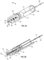
- the anchor assembly 50 generally comprises a coil 54 which may comprise any of a variety of materials such as stainless steel or Nitinol.
- the coil 54 extends helically between a proximal end 56 and a distal end 58.
- Distal end 58 is provided with a sharpened tip 59, and also carries a retention barb 61, configured to resist reverse rotation of the coil and detachment from tissue.
- the proximal end 56 of the coil 54 is carried by (attached to or formed integrally with) a hub 57 discussed in additional detail below.
- Extending distally from the hub 57 and within the coil 54 is an elongate core wire 62 having a sharp, tissue piercing distal end 64.
- the distal end 64 is positioned distally of the distal end 58 of the coil 54. This enables the sharp distal end 64 to pierce tissue upon contact, and prior to beginning rotation of the coil 54 to embed the coil 54 within the target tissue.
- Engaging the tip 64 prior to rotation of the anchor stabilizes the anchor against sideways movement allowing a single placement of the anchor 50 against tissue, and rotation of the coil 54 to engage tissue, without 'walking' of the anchor away from the desired target site as will be understood by those of skill in the art.
- a proximal end of the core wire 62 may be attached to the hub in any of a variety of ways, such as by soldering, brazing, adhesives and / or mechanical interference such as by entering an aperture in a sidewall or other surface of the hub 57.
- a radiopaque depth marker 66 is provided with an aperture 68 and is axially movably carried on the core wire 62.
- a distal stop 70 such as a radially outwardly extending protrusion or annular ridge is carried by the core wire 62, and spaced proximally of the sharpened distal end 64 to provide a core wire leading segment 72 on the distal side of the stop 70 so that the marker 66 cannot interfere with the tissue anchoring function of the distal tip 64.
- the stop 70 functions to limit distal travel of the marker 66.
- the marker 66 may be an annular structure such as a circular disc with a central aperture to receive the core wire 62.
- a coil spring 71 is concentrically carried over the core wire 62 and biases the radiopaque marker 66 in the distal direction.
- the radiopaque marker 66 is thus held in position against a proximal surface of the stop 70.
- the marker 66 rides on the surface of tissue at the target attachment site.
- the marker 66 rides proximally on the core wire 62 along with the tissue surface, compressing the coil spring 71 until the marker 66 is retracted proximally to the hub when the tissue anchor is fully embedded. This enables fluoroscopic visualization of the progress of the coil into tissue and of the fully engaged end point of embedding the coil 54 into the target tissue, by observing the changing distance between marker 66 and a reference such as the hub 57 or other radiopaque marker.
- the hub 57 comprises a proximal connector for engagement with a rotational driver as discussed elsewhere herein.
- the connector comprises an aperture such as a hexagonal aperture for removably engaging a complementary surface structure on the distal end of the driver.
- a suture 74 is secured to the anchor assembly 50, for example secured to the hub 57, coil 54 or core wire 62.
- the suture 74 is attached to a cross pin 76 which may be inserted through one or two apertures in the sidewall of the hub and across a central hub lumen.
- the suture may additionally carry one or two or more radiopaque markers 82 spaced apart from the hub 57, and may extend proximally through the proximal connector and a central lumen in the rotational driver.
- a suture lock guide such as a tubular sleeve 78 extends proximally from the hub 57 for at least about 2 mm or 4 mm or 8 mm but generally no more than about 5 cm or 2 cm depending upon desired performance.
- the guide sleeve 78 may comprise a flexible material such as ePTFE.
- a radiopaque marker band 80 is carried by the proximal end of sleeve 78 and spaced axially apart from the marker 82 on suture 74, to facilitate fluoroscopic visualization of the suture lock as it is advanced distally over the suture 74.
- the marker band 80 may be positioned in between an inner layer and an outer layer of ePTFE sleeve, such as may result from placing the band over the sleeve and inverting the sleeve over itself to entrap the ring.
- the suture lock guide may comprise any of a variety of structures such as a sleeve as illustrated or an alignment pin extending proximally from the hub and received within a lumen in the suture lock, for maintaining the orientation of the suture lock following detachment from the deployment catheter. Since the tension on the suture is optimized while the suture lock is held in place by the deployment catheter, any change in the orientation of the suture lock following release from the catheter would affect tension on the leaflet and potentially negatively affect the therapeutic value of the implant.
- the suture lock guide helps maintain constant the maximum distance between the ventricular anchor and the leaflet anchor both pre and post deployment from the catheter. In this manner the maximum tension on the leaflet suture (during systole) remains unchanged after the suture lock has been locked, both before and after detachment of the catheter.
- the helical anchor assembly 50 may be delivered by a ventricular anchor delivery subsystem 300.
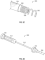
- FIGS. 2C - 2E illustrate various views of a ventricular anchor delivery subsystem 300 and its components.
- FIG. 2C depicts a perspective view of a distal end of the subsystem 300.
- FIG. 2D depicts a perspective view of a proximal end of the subsystem 300.
- FIG. 2E depicts a partially exploded view of a distal end of the subsystem 300.
- the ventricular anchor delivery subsystem 300 may comprise an outer sheath 304, a driver (comprising shaft 307 and head 306), an anchor hub 308, and an anchor 302.
- the anchor may be a helical anchor 302 and the drive head 306 can be configured to rotate the helical anchor 302.
- the helical anchor 302 may comprise an inner diameter configured to be received over the outer diameter of an anchor hub 308.
- the helical anchor 302 may be securely fixed secured to the anchor hub 308 by an interference fit or other frictional engagement, soldering or other known attachment technique.
- the anchor hub 308 may be left implanted along with the helical anchor 302.
- the anchor hub 308 may comprise a lumen positioned substantially along a central axis of the anchor hub 308 for receiving a suture 74 ( FIG. 2A ) and attaching the suture 74 to the helical anchor 302.
- the suture 74 may comprise an attachment element (e.g. a knot or a washer) with a diameter sized to prevent the suture 74 from being pulled proximally through the anchor hub 308 lumen.
- the suture 74 may be knotted on a distal side of the lumen.
- the suture 74 may be tied to the anchor hub 308 (e.g., passed through the lumen, wrapped around a structure such as the outer surface or a cross pin 76 as shown in Figure 2B , and tied to itself).
- the helical anchor 302 may comprise a distal section of windings and a proximal section of windings.
- the proximal section of windings may be spaced closer together than the distal section of windings and may be configured for securing the helical anchor 302 to the anchor hub 308.
- the distal section of windings may be spaced further apart than the proximal section of windings and may be configured for insertion into the ventricular tissue.
- the anchor hub 308 may comprise an enlarged cross-section at its proximal end configured to abut the helical anchor 302 and/or prevent the helical anchor 302 from advancing proximally over the proximal end of the anchor hub 308.
- Other helical anchors such as those described elsewhere herein, may be configured to be used with the ventricular anchor delivery subsystem 300 described herein as well.
- the proximal face of the helical anchor 308 may comprise a recess for receiving an extending portion 306' of the driver head 306.
- the recess may be non-circular (e.g., oblong or polygonal such as hexagonal) such that it is configured to transfer torque from the driver to the anchor hub 308 upon rotation of the driver.
- the recess may be positioned around the central lumen of the anchor hub 308.
- the anchor hub 308 may comprise an extending portion and the driver 306 may have a complementary recess.
- the driver head 306 may be generally cylindrical, with a distally facing post or aperture with a complementary configuration to rotationally engage the corresponding component on the anchor.
- the driver head 306 may be fixedly coupled to a drive shaft 307.
- the driver may comprise a central lumen through the driver head 306 and drive shaft 307 configured to receive the suture 74.
- the central lumen of the driver may be configured to be aligned with the central lumen of the anchor hub 308.
- the drive shaft 307 may be received within a guide shaft 305.
- the diameter of the driver head 306 may be larger than the inner diameter of the guide shaft 305.
- the outer sheath 304 may be sized to receive the guide shaft 305 as well as the driver head 306, the anchor hub 308, and the helical anchor 302.
- Rotation of the drive shaft 307 may cause the driver head 306, the anchor hub 308, and the helical anchor 302 to rotate thereby screwing the ventricular anchor 302 into the ventricular tissue.
- Rotation of the driver 309 may axially advance the driver 309, anchor hub 308, and helical screw 302 in a distal direction with respect to the outer sheath 304.
- the drive shaft 307 may be rotated manually by a user using a drive handle 312, as shown in FIG. 2D .
- the proximal end of the ventricular anchor delivery subsystem 300 may comprise first and second hemostasis valves 314, 316.
- the first hemostasis valve 314 may be positioned distal to the drive handle 312 and may provide access to the guide shaft 305.
- the second hemostasis valve 316 may be positioned proximal to the drive handle 312 and may provide access to the central lumen of the driver.
- the ventricular anchor suture (not shown) may extend through the second hemostasis valve 316.
- the non-implanted components of the ventricular anchor delivery subsystem 300 may be removed from the delivery catheter 100 and subsequent subsystems may be placed in the delivery catheter 100 for completing implantation of the neo chordae.
- the ventricular anchor delivery subsystem 300 and subsequent subsystems such as the leaflet anchor delivery subsystem 330 may be positioned within the delivery catheter 100 at the same time and in certain arrangements the tissue and leaflet anchors can both be preloaded into the delivery catheter.
- the implantation of the ventricular anchor may be performed in a different order (e.g., after the implantation of the leaflet anchor).
- the ventricular anchor delivery components may be proximally retracted over a proximal end of the suture 74, which may remain extending through the delivery catheter 100 to the ventricular anchor 302.
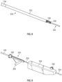
- FIGS. 3-6 depict the deployment of the leaflet anchor.
- the ventricular anchor 32 has been deployed and is tethered to the catheter 100 by a ventricular anchor suture 74 and the ventricular anchor subsystem has been removed.
- the leaflet anchor is carried within a needle 338, shown aimed at a target site on the atrial side of the leaflet.
- the needle 338 is axially reciprocally carried within the catheter 100, such as within a tubular sleeve 332 advanceable through the catheter 100. Additional details of the needle and needle driver are discussed below.
- the needle can cross through the leaflet from the atrium to the ventricle and a preloaded suture can then be advanced into the ventricle.
- the suture can then be used to collapse the pledget against the ventricular side of the leaflet to anchor the suture to the leaflet as shown in Figure 4 .
- the pledget forms a radially enlargeable leaflet anchor.
- other forms of a radially enlargeable leaflet anchor can be used.
- the leaflet anchor deployment subassembly is provided with a temporary anchor for capturing and stabilizing the leaflet while the needle tip 338 is advanced therethrough at a target side.
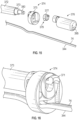
- a distal end 400 of delivery tube 332 or other system component carries a temporary tissue anchor such as a helical tissue anchor 402.
- Anchor 402 may be similar to ventricular anchor 54 except that temporary anchor 402 does not have a distal barb since it is intended to be only momentarily in engagement with the leaflet.
- the anchor 402 thus comprises a helical element 406 which terminates in a distal tip 408.
- the distal tip 408 is positioned at a target site on the surface of the leaflet, and the helical element 406 is rotated about its axis to engage and penetrate the leaflet.
- the needle tip 338 may be optionally engaged with the leaflet prior to rotation of the helical element 406, and utilized to stabilize the anchor against moving away from the target site in response to rotation, in a manner similar to that discussed in connection with the ventricular anchor and Figures 2A and 2B .
- the apertures may extend through the pledget 340 and through the portion of the embedded portion of the suture 344 which is integral with the pledget 340.
- the embedded portion of the suture 344 may be at least partially flatted within the pledget 340.
- the apertures may be placed substantially near the center of the pledget (e.g., immediately to the left or right of the embedded suture 344 or alternating between the left and right side of the suture 344).
- the suture 344 When deployed the suture 344 may be effectively joined to a distal end of the pledget 340 (e.g., the suture 344 may loop back to where it inserts between the pledget sheets).
- the pledget 340 may be formed such that the wings 341, 342 are approximately the same size or they may be formed to be different sizes. Upon proximal retraction of the leaflet suture 344, the pledget 340 may be folded to assume an accordion-like conformation, as depicted in FIG. 6A . The pledget 340 may assume a conformation comprising a substantially planar proximal surface which is approximately perpendicular to the longitudinal axis of the leaflet suture 344. This conformation may facilitate anchoring the suture 344 in the leaflet. Upon anchoring the leaflet suture 344 in the leaflet, the leaflet anchor delivery subsystem 340 may be withdrawn from the delivery catheter 100. The leaflet anchor delivery components may be proximally retracted over a proximal end of the suture 344, which may remain extending through the delivery catheter 100 to the leaflet anchor 340, alongside the ventricular anchor suture 74.
- the cutter head 375 is configured to advance over the retainer element 377 in such a fashion that the channel in the cutter head 375 retaining the sutures 74, 344 becomes increasingly spatially occupied by the blade 379. As the blade 379 is forced into the channel of the cutter head 375, the blade 379 shears the sutures 74, 344. Application of proximal tension to the sutures 74, 344 may facilitate the cutting of the sutures 74, 344. In other embodiments, different actuations (e.g., rotation of a cutting catheter) can be configured to sever the sutures 74, 344.
- more than two sutures may be employed and may be locked within the suture lock 376 and severed by the suture lock delivery subsystem 370 in the same fashion.
- advancement of the cutter head 375 over the retainer element 377 may facilitate the disengagement of the retainer catheter 373 from the suture lock 376.
- the cutter head 375 may advance to a distal position where it is configured to stabilize the suture lock 376, allowing the retainer catheter 373 to be axially and/or rotationally disengaged from the suture lock 376.
- FIG. 19 illustrates a side view of an example of a suture lock 376 (shown with its outer casing/shell removed).
- the sutures may pass through the suture lock 376 from a distal end to a proximal end as described elsewhere herein.
- the suture lock 376 may comprise a screw 382 configured to distally advance or proximally retract a push wedge 384, depending on the direction of rotation of the screw.
- the screw 382 may be rotated by a torque shaft 388.
- the torque shaft 388 may comprise a driver head configured to mate with recess 381 (e.g., a polygonal recess or other non-circular shaped recess, as shown in FIG.
- the torque shaft 388 may extend through an internal lumen of the retainer catheter 373.
- the torque shaft 388 may be rotated at its proximal end by a knob 398 or other actuation mechanism positioned at a proximal end of the subsystem handle 396.
- the handle 396 may include a hemostasis valve 397.
- the sutures 311, 344 may pass through the hemostasis valve 397.
- Advancement of the push wedge 384 by the torque shaft 388 may cause a ramp or angled surface 386 to gradually compress one or more springs, such as spring pins 388.
- the springs bias the clamp upward to open the suture path until forced closure by rotation of the torque shaft 388.
- Compression of the one or more springs 388 may force a clamp 390 downward on the sutures 311, 344, compressing the sutures 311, 344 between two opposing surfaces.
- the clamp 390 and the opposing surface 392 may have notched surfaces configured to mate with each other at discrete increments.
- the mated notched surfaces may provide enhanced friction and in some implementations mechanical interference for retention of the sutures 311, 344 between the opposing surfaces such that they cannot be withdrawn, either proximally or distally, from the suture lock 376.
- the tightening may be reversible by rotating the torque shaft in an opposite direction.
- FIG. 12 depicts the retraction of the suture lock delivery subsystem 370 after the sutures 74, 344 have been cut. Once the suture lock delivery subsystem 370 has been removed from the delivery catheter 100, the delivery catheter 100 may be withdrawn from the body.
Landscapes
- Health & Medical Sciences (AREA)
- Life Sciences & Earth Sciences (AREA)
- Surgery (AREA)
- General Health & Medical Sciences (AREA)
- Public Health (AREA)
- Biomedical Technology (AREA)
- Heart & Thoracic Surgery (AREA)
- Engineering & Computer Science (AREA)
- Animal Behavior & Ethology (AREA)
- Veterinary Medicine (AREA)
- Cardiology (AREA)
- Molecular Biology (AREA)
- Nuclear Medicine, Radiotherapy & Molecular Imaging (AREA)
- Medical Informatics (AREA)
- Oral & Maxillofacial Surgery (AREA)
- Transplantation (AREA)
- Vascular Medicine (AREA)
- Rheumatology (AREA)
- Prostheses (AREA)
- Surgical Instruments (AREA)
Priority Applications (1)
| Application Number | Priority Date | Filing Date | Title |
|---|---|---|---|
| EP25179321.2A EP4585188A3 (en) | 2018-03-12 | 2019-03-08 | Apparatus for mitral valve chord repair |
Applications Claiming Priority (2)
| Application Number | Priority Date | Filing Date | Title |
|---|---|---|---|
| US201862641612P | 2018-03-12 | 2018-03-12 | |
| PCT/US2019/021480 WO2019177909A1 (en) | 2018-03-12 | 2019-03-08 | Method and apparatus for mitral valve chord repair |
Related Child Applications (2)
| Application Number | Title | Priority Date | Filing Date |
|---|---|---|---|
| EP25179321.2A Division EP4585188A3 (en) | 2018-03-12 | 2019-03-08 | Apparatus for mitral valve chord repair |
| EP25179321.2A Division-Into EP4585188A3 (en) | 2018-03-12 | 2019-03-08 | Apparatus for mitral valve chord repair |
Publications (3)
| Publication Number | Publication Date |
|---|---|
| EP3764919A1 EP3764919A1 (en) | 2021-01-20 |
| EP3764919A4 EP3764919A4 (en) | 2022-01-19 |
| EP3764919B1 true EP3764919B1 (en) | 2025-07-02 |
Family
ID=67906923
Family Applications (2)
| Application Number | Title | Priority Date | Filing Date |
|---|---|---|---|
| EP19766750.4A Active EP3764919B1 (en) | 2018-03-12 | 2019-03-08 | Apparatus for mitral valve chord repair |
| EP25179321.2A Pending EP4585188A3 (en) | 2018-03-12 | 2019-03-08 | Apparatus for mitral valve chord repair |
Family Applications After (1)
| Application Number | Title | Priority Date | Filing Date |
|---|---|---|---|
| EP25179321.2A Pending EP4585188A3 (en) | 2018-03-12 | 2019-03-08 | Apparatus for mitral valve chord repair |
Country Status (8)
| Country | Link |
|---|---|
| EP (2) | EP3764919B1 (https=) |
| JP (3) | JP7324215B2 (https=) |
| CN (2) | CN112203594B (https=) |
| AU (2) | AU2019234447B2 (https=) |
| CA (2) | CA3093693A1 (https=) |
| ES (1) | ES3039962T3 (https=) |
| TW (1) | TW201940128A (https=) |
| WO (1) | WO2019177909A1 (https=) |
Families Citing this family (15)
| Publication number | Priority date | Publication date | Assignee | Title |
|---|---|---|---|---|
| CN121796784A (zh) | 2015-12-30 | 2026-04-07 | 管道医疗技术股份有限公司 | 二尖瓣瓣叶拴系 |
| US11083580B2 (en) | 2016-12-30 | 2021-08-10 | Pipeline Medical Technologies, Inc. | Method of securing a leaflet anchor to a mitral valve leaflet |
| US9877833B1 (en) | 2016-12-30 | 2018-01-30 | Pipeline Medical Technologies, Inc. | Method and apparatus for transvascular implantation of neo chordae tendinae |
| US12472062B2 (en) | 2016-12-30 | 2025-11-18 | Pipeline Medical Technologies, Inc. | Method and apparatus for mitral valve chord repair |
| US10925731B2 (en) | 2016-12-30 | 2021-02-23 | Pipeline Medical Technologies, Inc. | Method and apparatus for transvascular implantation of neo chordae tendinae |
| US11376127B2 (en) | 2017-12-20 | 2022-07-05 | W. L. Gore & Associates, Inc. | Artificial chordae tendineae repair devices and delivery thereof |
| CN121129502A (zh) | 2018-12-12 | 2025-12-16 | 管道医疗技术公司 | 用于二尖瓣腱索修复的方法和装置 |
| CN114502082B (zh) * | 2019-09-23 | 2025-03-25 | W.L.戈尔及同仁股份有限公司 | 用于二尖瓣腱索修复的锚定件 |
| US12350155B2 (en) | 2020-06-17 | 2025-07-08 | Pipeline Medical Technologies, Inc. | Method and apparatus for mitral valve chord repair |
| CN112891024B (zh) * | 2021-01-14 | 2025-08-08 | 上海汇禾医疗科技有限公司 | 锚定器械 |
| CN114795579B (zh) * | 2021-01-27 | 2025-06-10 | 上海汇禾医疗科技有限公司 | 锚定器械及锚定件 |
| CN113081111A (zh) * | 2021-04-02 | 2021-07-09 | 葛均波 | 锚定装置 |
| JPWO2023191058A1 (https=) * | 2022-03-31 | 2023-10-05 | ||
| CN119632726B (zh) * | 2023-09-15 | 2025-09-19 | 杭州德晋医疗科技有限公司 | 用于部署心脏锚固器的系统 |
| CN121015351B (zh) * | 2025-10-21 | 2026-01-30 | 华中科技大学同济医学院附属协和医院 | 一种瓣膜腱索辅助重建装置及方法 |
Family Cites Families (12)
| Publication number | Priority date | Publication date | Assignee | Title |
|---|---|---|---|---|
| US7390329B2 (en) * | 2004-05-07 | 2008-06-24 | Usgi Medical, Inc. | Methods for grasping and cinching tissue anchors |
| DE102005062657A1 (de) * | 2005-12-28 | 2007-07-12 | Osypka, Peter, Dr.-Ing. | Vorrichtung zum Verschliessen einer in einer Herztrennwand befindlichen Öffnung |
| EP3345572A1 (en) * | 2007-02-14 | 2018-07-11 | Edwards Lifesciences Corporation | Suture and method for repairing heart |
| US9131939B1 (en) * | 2008-02-27 | 2015-09-15 | Mitralign, Inc. | Device for percutaneously delivering a cardiac implant through the application of direct actuation forces external to the body |
| US9180007B2 (en) * | 2009-10-29 | 2015-11-10 | Valtech Cardio, Ltd. | Apparatus and method for guide-wire based advancement of an adjustable implant |
| EP2693985B1 (en) * | 2011-04-04 | 2020-07-29 | The Medical Research, Infrastructure, And Health Services Fund Of The Tel Aviv Medical Center | Device for heart valve repair |
| CN104758089B (zh) * | 2014-01-08 | 2018-03-30 | 库克医学技术有限责任公司 | 用于塞住经皮心脏瓣膜泄漏的ecm条带 |
| EP3157607B1 (en) * | 2014-06-19 | 2019-08-07 | 4Tech Inc. | Cardiac tissue cinching |
| US20160256269A1 (en) * | 2015-03-05 | 2016-09-08 | Mitralign, Inc. | Devices for treating paravalvular leakage and methods use thereof |
| US9877833B1 (en) * | 2016-12-30 | 2018-01-30 | Pipeline Medical Technologies, Inc. | Method and apparatus for transvascular implantation of neo chordae tendinae |
| US10925731B2 (en) * | 2016-12-30 | 2021-02-23 | Pipeline Medical Technologies, Inc. | Method and apparatus for transvascular implantation of neo chordae tendinae |
| CN107569301B (zh) * | 2017-07-31 | 2023-10-31 | 杭州德晋医疗科技有限公司 | 人工腱索及其人工腱索植入系统 |
-
2019
- 2019-03-08 JP JP2020548744A patent/JP7324215B2/ja active Active
- 2019-03-08 ES ES19766750T patent/ES3039962T3/es active Active
- 2019-03-08 CA CA3093693A patent/CA3093693A1/en active Pending
- 2019-03-08 EP EP19766750.4A patent/EP3764919B1/en active Active
- 2019-03-08 AU AU2019234447A patent/AU2019234447B2/en active Active
- 2019-03-08 CN CN201980023765.8A patent/CN112203594B/zh active Active
- 2019-03-08 EP EP25179321.2A patent/EP4585188A3/en active Pending
- 2019-03-08 CA CA3292467A patent/CA3292467A1/en active Pending
- 2019-03-08 CN CN202510247948.5A patent/CN120241152A/zh active Pending
- 2019-03-08 WO PCT/US2019/021480 patent/WO2019177909A1/en not_active Ceased
- 2019-03-12 TW TW108108273A patent/TW201940128A/zh unknown
-
2023
- 2023-07-28 JP JP2023122932A patent/JP7776470B2/ja active Active
-
2025
- 2025-03-04 AU AU2025201566A patent/AU2025201566A1/en active Pending
- 2025-07-04 JP JP2025113607A patent/JP2025129360A/ja active Pending
Also Published As
| Publication number | Publication date |
|---|---|
| AU2019234447A8 (en) | 2024-12-12 |
| AU2025201566A1 (en) | 2025-03-20 |
| EP4585188A3 (en) | 2025-10-08 |
| AU2019234447B2 (en) | 2024-12-12 |
| WO2019177909A1 (en) | 2019-09-19 |
| JP7324215B2 (ja) | 2023-08-09 |
| ES3039962T3 (en) | 2025-10-28 |
| EP3764919A4 (en) | 2022-01-19 |
| JP2025129360A (ja) | 2025-09-04 |
| CA3292467A1 (en) | 2026-03-02 |
| CN120241152A (zh) | 2025-07-04 |
| EP3764919A1 (en) | 2021-01-20 |
| AU2019234447A1 (en) | 2020-10-15 |
| JP2023129680A (ja) | 2023-09-14 |
| JP7776470B2 (ja) | 2025-11-26 |
| EP4585188A2 (en) | 2025-07-16 |
| JP2021517485A (ja) | 2021-07-26 |
| CN112203594A (zh) | 2021-01-08 |
| CN112203594B (zh) | 2025-03-25 |
| AU2019234447A2 (en) | 2020-10-22 |
| TW201940128A (zh) | 2019-10-16 |
| CA3093693A1 (en) | 2019-09-19 |
Similar Documents
| Publication | Publication Date | Title |
|---|---|---|
| US11690719B2 (en) | Leaflet capture and anchor deployment system | |
| EP3764919B1 (en) | Apparatus for mitral valve chord repair | |
| US20230404756A1 (en) | Leaflet capture and anchor deployment system | |
| JP7644202B2 (ja) | 弁輪形成システムおよびそのための係止ツール | |
| JP7741041B2 (ja) | 新生腱索の経血管的埋め込み方法及び装置 | |
| US11696828B2 (en) | Method and apparatus for mitral valve chord repair | |
| JP2021517485A5 (https=) | ||
| US8926697B2 (en) | Closed band for percutaneous annuloplasty | |
| US12472062B2 (en) | Method and apparatus for mitral valve chord repair | |
| US20260047930A1 (en) | Method and apparatus for mitral valve chord repair |
Legal Events
| Date | Code | Title | Description |
|---|---|---|---|
| STAA | Information on the status of an ep patent application or granted ep patent |
Free format text: STATUS: THE INTERNATIONAL PUBLICATION HAS BEEN MADE |
|
| PUAI | Public reference made under article 153(3) epc to a published international application that has entered the european phase |
Free format text: ORIGINAL CODE: 0009012 |
|
| STAA | Information on the status of an ep patent application or granted ep patent |
Free format text: STATUS: REQUEST FOR EXAMINATION WAS MADE |
|
| 17P | Request for examination filed |
Effective date: 20200925 |
|
| AK | Designated contracting states |
Kind code of ref document: A1 Designated state(s): AL AT BE BG CH CY CZ DE DK EE ES FI FR GB GR HR HU IE IS IT LI LT LU LV MC MK MT NL NO PL PT RO RS SE SI SK SM TR |
|
| AX | Request for extension of the european patent |
Extension state: BA ME |
|
| DAV | Request for validation of the european patent (deleted) | ||
| DAX | Request for extension of the european patent (deleted) | ||
| RIC1 | Information provided on ipc code assigned before grant |
Ipc: A61B 90/00 20160101ALN20211028BHEP Ipc: A61B 17/06 20060101ALN20211028BHEP Ipc: A61B 17/00 20060101ALN20211028BHEP Ipc: A61F 2/24 20060101ALI20211028BHEP Ipc: A61F 2/02 20060101ALI20211028BHEP Ipc: A61F 2/00 20060101ALI20211028BHEP Ipc: A61B 17/04 20060101AFI20211028BHEP |
|
| A4 | Supplementary search report drawn up and despatched |
Effective date: 20211217 |
|
| RIC1 | Information provided on ipc code assigned before grant |
Ipc: A61B 90/00 20160101ALN20211213BHEP Ipc: A61B 17/06 20060101ALN20211213BHEP Ipc: A61B 17/00 20060101ALN20211213BHEP Ipc: A61F 2/24 20060101ALI20211213BHEP Ipc: A61F 2/02 20060101ALI20211213BHEP Ipc: A61F 2/00 20060101ALI20211213BHEP Ipc: A61B 17/04 20060101AFI20211213BHEP |
|
| RAP3 | Party data changed (applicant data changed or rights of an application transferred) |
Owner name: PIPELINE MEDICAL TECHNOLOGIES, INC. |
|
| STAA | Information on the status of an ep patent application or granted ep patent |
Free format text: STATUS: EXAMINATION IS IN PROGRESS |
|
| 17Q | First examination report despatched |
Effective date: 20230405 |
|
| RAP3 | Party data changed (applicant data changed or rights of an application transferred) |
Owner name: PIPELINE MEDICAL TECHNOLOGIES, INC. |
|
| GRAP | Despatch of communication of intention to grant a patent |
Free format text: ORIGINAL CODE: EPIDOSNIGR1 |
|
| STAA | Information on the status of an ep patent application or granted ep patent |
Free format text: STATUS: GRANT OF PATENT IS INTENDED |
|
| RIC1 | Information provided on ipc code assigned before grant |
Ipc: A61B 90/00 20160101ALN20250115BHEP Ipc: A61B 17/06 20060101ALN20250115BHEP Ipc: A61B 17/00 20060101ALN20250115BHEP Ipc: A61F 2/24 20060101ALI20250115BHEP Ipc: A61F 2/02 20060101ALI20250115BHEP Ipc: A61F 2/00 20060101ALI20250115BHEP Ipc: A61B 17/04 20060101AFI20250115BHEP |
|
| INTG | Intention to grant announced |
Effective date: 20250128 |
|
| RIC1 | Information provided on ipc code assigned before grant |
Ipc: A61B 90/00 20160101ALN20250121BHEP Ipc: A61B 17/06 20060101ALN20250121BHEP Ipc: A61B 17/00 20060101ALN20250121BHEP Ipc: A61F 2/24 20060101ALI20250121BHEP Ipc: A61F 2/02 20060101ALI20250121BHEP Ipc: A61F 2/00 20060101ALI20250121BHEP Ipc: A61B 17/04 20060101AFI20250121BHEP |
|
| GRAS | Grant fee paid |
Free format text: ORIGINAL CODE: EPIDOSNIGR3 |
|
| GRAA | (expected) grant |
Free format text: ORIGINAL CODE: 0009210 |
|
| STAA | Information on the status of an ep patent application or granted ep patent |
Free format text: STATUS: THE PATENT HAS BEEN GRANTED |
|
| AK | Designated contracting states |
Kind code of ref document: B1 Designated state(s): AL AT BE BG CH CY CZ DE DK EE ES FI FR GB GR HR HU IE IS IT LI LT LU LV MC MK MT NL NO PL PT RO RS SE SI SK SM TR |
|
| REG | Reference to a national code |
Ref country code: GB Ref legal event code: FG4D |
|
| REG | Reference to a national code |
Ref country code: CH Ref legal event code: EP |
|
| P01 | Opt-out of the competence of the unified patent court (upc) registered |
Free format text: CASE NUMBER: APP_27211/2025 Effective date: 20250606 |
|
| REG | Reference to a national code |
Ref country code: DE Ref legal event code: R096 Ref document number: 602019071958 Country of ref document: DE |
|
| REG | Reference to a national code |
Ref country code: IE Ref legal event code: FG4D |
|
| REG | Reference to a national code |
Ref country code: ES Ref legal event code: FG2A Ref document number: 3039962 Country of ref document: ES Kind code of ref document: T3 Effective date: 20251028 |
|
| REG | Reference to a national code |
Ref country code: NL Ref legal event code: MP Effective date: 20250702 |
|
| PG25 | Lapsed in a contracting state [announced via postgrant information from national office to epo] |
Ref country code: PT Free format text: LAPSE BECAUSE OF FAILURE TO SUBMIT A TRANSLATION OF THE DESCRIPTION OR TO PAY THE FEE WITHIN THE PRESCRIBED TIME-LIMIT Effective date: 20251103 |
|
| PG25 | Lapsed in a contracting state [announced via postgrant information from national office to epo] |
Ref country code: NL Free format text: LAPSE BECAUSE OF FAILURE TO SUBMIT A TRANSLATION OF THE DESCRIPTION OR TO PAY THE FEE WITHIN THE PRESCRIBED TIME-LIMIT Effective date: 20250702 |
|
| REG | Reference to a national code |
Ref country code: AT Ref legal event code: MK05 Ref document number: 1808337 Country of ref document: AT Kind code of ref document: T Effective date: 20250702 |
|
| PG25 | Lapsed in a contracting state [announced via postgrant information from national office to epo] |
Ref country code: IS Free format text: LAPSE BECAUSE OF FAILURE TO SUBMIT A TRANSLATION OF THE DESCRIPTION OR TO PAY THE FEE WITHIN THE PRESCRIBED TIME-LIMIT Effective date: 20251102 |
|
| PG25 | Lapsed in a contracting state [announced via postgrant information from national office to epo] |
Ref country code: NO Free format text: LAPSE BECAUSE OF FAILURE TO SUBMIT A TRANSLATION OF THE DESCRIPTION OR TO PAY THE FEE WITHIN THE PRESCRIBED TIME-LIMIT Effective date: 20251002 |
|
| REG | Reference to a national code |
Ref country code: LT Ref legal event code: MG9D |
|
| PG25 | Lapsed in a contracting state [announced via postgrant information from national office to epo] |
Ref country code: AT Free format text: LAPSE BECAUSE OF FAILURE TO SUBMIT A TRANSLATION OF THE DESCRIPTION OR TO PAY THE FEE WITHIN THE PRESCRIBED TIME-LIMIT Effective date: 20250702 |
|
| PG25 | Lapsed in a contracting state [announced via postgrant information from national office to epo] |
Ref country code: FI Free format text: LAPSE BECAUSE OF FAILURE TO SUBMIT A TRANSLATION OF THE DESCRIPTION OR TO PAY THE FEE WITHIN THE PRESCRIBED TIME-LIMIT Effective date: 20250702 |
|
| PG25 | Lapsed in a contracting state [announced via postgrant information from national office to epo] |
Ref country code: HR Free format text: LAPSE BECAUSE OF FAILURE TO SUBMIT A TRANSLATION OF THE DESCRIPTION OR TO PAY THE FEE WITHIN THE PRESCRIBED TIME-LIMIT Effective date: 20250702 |
|
| PG25 | Lapsed in a contracting state [announced via postgrant information from national office to epo] |
Ref country code: GR Free format text: LAPSE BECAUSE OF FAILURE TO SUBMIT A TRANSLATION OF THE DESCRIPTION OR TO PAY THE FEE WITHIN THE PRESCRIBED TIME-LIMIT Effective date: 20251003 |
|
| PG25 | Lapsed in a contracting state [announced via postgrant information from national office to epo] |
Ref country code: SE Free format text: LAPSE BECAUSE OF FAILURE TO SUBMIT A TRANSLATION OF THE DESCRIPTION OR TO PAY THE FEE WITHIN THE PRESCRIBED TIME-LIMIT Effective date: 20250702 Ref country code: CZ Free format text: LAPSE BECAUSE OF FAILURE TO SUBMIT A TRANSLATION OF THE DESCRIPTION OR TO PAY THE FEE WITHIN THE PRESCRIBED TIME-LIMIT Effective date: 20250702 |
|
| PG25 | Lapsed in a contracting state [announced via postgrant information from national office to epo] |
Ref country code: LV Free format text: LAPSE BECAUSE OF FAILURE TO SUBMIT A TRANSLATION OF THE DESCRIPTION OR TO PAY THE FEE WITHIN THE PRESCRIBED TIME-LIMIT Effective date: 20250702 |
|
| PG25 | Lapsed in a contracting state [announced via postgrant information from national office to epo] |
Ref country code: PL Free format text: LAPSE BECAUSE OF FAILURE TO SUBMIT A TRANSLATION OF THE DESCRIPTION OR TO PAY THE FEE WITHIN THE PRESCRIBED TIME-LIMIT Effective date: 20250702 Ref country code: BG Free format text: LAPSE BECAUSE OF FAILURE TO SUBMIT A TRANSLATION OF THE DESCRIPTION OR TO PAY THE FEE WITHIN THE PRESCRIBED TIME-LIMIT Effective date: 20250702 |
|
| PG25 | Lapsed in a contracting state [announced via postgrant information from national office to epo] |
Ref country code: RS Free format text: LAPSE BECAUSE OF FAILURE TO SUBMIT A TRANSLATION OF THE DESCRIPTION OR TO PAY THE FEE WITHIN THE PRESCRIBED TIME-LIMIT Effective date: 20251002 |
|
| PG25 | Lapsed in a contracting state [announced via postgrant information from national office to epo] |
Ref country code: SM Free format text: LAPSE BECAUSE OF FAILURE TO SUBMIT A TRANSLATION OF THE DESCRIPTION OR TO PAY THE FEE WITHIN THE PRESCRIBED TIME-LIMIT Effective date: 20250702 |
|
| PGFP | Annual fee paid to national office [announced via postgrant information from national office to epo] |
Ref country code: GB Payment date: 20260219 Year of fee payment: 8 |
|
| PG25 | Lapsed in a contracting state [announced via postgrant information from national office to epo] |
Ref country code: DK Free format text: LAPSE BECAUSE OF FAILURE TO SUBMIT A TRANSLATION OF THE DESCRIPTION OR TO PAY THE FEE WITHIN THE PRESCRIBED TIME-LIMIT Effective date: 20250702 |
|
| PGFP | Annual fee paid to national office [announced via postgrant information from national office to epo] |
Ref country code: DE Payment date: 20260219 Year of fee payment: 8 |
|
| PGFP | Annual fee paid to national office [announced via postgrant information from national office to epo] |
Ref country code: IT Payment date: 20260219 Year of fee payment: 8 |
|
| PGFP | Annual fee paid to national office [announced via postgrant information from national office to epo] |
Ref country code: FR Payment date: 20260219 Year of fee payment: 8 |
|
| PG25 | Lapsed in a contracting state [announced via postgrant information from national office to epo] |
Ref country code: EE Free format text: LAPSE BECAUSE OF FAILURE TO SUBMIT A TRANSLATION OF THE DESCRIPTION OR TO PAY THE FEE WITHIN THE PRESCRIBED TIME-LIMIT Effective date: 20250702 Ref country code: SK Free format text: LAPSE BECAUSE OF FAILURE TO SUBMIT A TRANSLATION OF THE DESCRIPTION OR TO PAY THE FEE WITHIN THE PRESCRIBED TIME-LIMIT Effective date: 20250702 |