EP3764548B1 - Method, computer program, and computer system for lossless compression of a multichannel electrocardiogram signal - Google Patents
Method, computer program, and computer system for lossless compression of a multichannel electrocardiogram signal Download PDFInfo
- Publication number
- EP3764548B1 EP3764548B1 EP19460036.7A EP19460036A EP3764548B1 EP 3764548 B1 EP3764548 B1 EP 3764548B1 EP 19460036 A EP19460036 A EP 19460036A EP 3764548 B1 EP3764548 B1 EP 3764548B1
- Authority
- EP
- European Patent Office
- Prior art keywords
- channel
- channels
- signal
- cross
- predictors
- Prior art date
- Legal status (The legal status is an assumption and is not a legal conclusion. Google has not performed a legal analysis and makes no representation as to the accuracy of the status listed.)
- Active
Links
Images


Classifications
-
- H—ELECTRICITY
- H03—ELECTRONIC CIRCUITRY
- H03M—CODING; DECODING; CODE CONVERSION IN GENERAL
- H03M7/00—Conversion of a code where information is represented by a given sequence or number of digits to a code where the same, similar or subset of information is represented by a different sequence or number of digits
- H03M7/30—Compression; Expansion; Suppression of unnecessary data, e.g. redundancy reduction
- H03M7/3059—Digital compression and data reduction techniques where the original information is represented by a subset or similar information, e.g. lossy compression
- H03M7/3064—Segmenting
-
- H—ELECTRICITY
- H03—ELECTRONIC CIRCUITRY
- H03M—CODING; DECODING; CODE CONVERSION IN GENERAL
- H03M7/00—Conversion of a code where information is represented by a given sequence or number of digits to a code where the same, similar or subset of information is represented by a different sequence or number of digits
- H03M7/30—Compression; Expansion; Suppression of unnecessary data, e.g. redundancy reduction
- H03M7/3068—Precoding preceding compression, e.g. Burrows-Wheeler transformation
- H03M7/3071—Prediction
-
- H—ELECTRICITY
- H03—ELECTRONIC CIRCUITRY
- H03M—CODING; DECODING; CODE CONVERSION IN GENERAL
- H03M7/00—Conversion of a code where information is represented by a given sequence or number of digits to a code where the same, similar or subset of information is represented by a different sequence or number of digits
- H03M7/30—Compression; Expansion; Suppression of unnecessary data, e.g. redundancy reduction
- H03M7/70—Type of the data to be coded, other than image and sound
Definitions
- the present invention relates to a method for lossless compression of a multichannel electrocardiogram signal, dedicated for portable systems of electrocardiogram (ECG) data acquisition. It also relates to a computer program and computer system to carry out the method according to the invention.
- ECG electrocardiogram
- the main diagnostic signal used for the heart diagnosis is the electrocardiogram (ECG), collected using electrodes placed at the patient's body and device converting the analog signal into digital, discrete time sample.
- ECG electrocardiogram
- the automated diagnosis using ECG is performed directly in the portable device carried by a patient.
- publication "Implementation of a portable device for real-time ECG signal analysis”, Taegyun Jeon, Byoungho Kim, Moongu Jeon and Byung-Geun Lee, BioMedical Engineering OnLine 2014 describes a portable ECG device with compact and effective architecture for detecting atrial fibrillation (AFib) and myocardial ischemia.
- the device allows real-time electrocardiogram (ECG) signal acquisition and analysis for cardiac diseases.
- ECG electrocardiogram
- This device has been built and evaluated for high quality of signals, accurate detection as well as low computational complexity. Because of reduced computational complexity, the ARM processor was able to process up to a thousand samples per second, and this allowed real-time acquisition and diagnosis of heart disease.
- Effectiveness of the transmission can be increased if the volume of the data is decreased using energy-efficient compression method.
- ECG electrocardiogram
- the proposed algorithm is aimed at lowering the average complexity per task by sharing the computational load among multiple essential signal-processing tasks needed for wearable devices.
- the compression algorithm which is based on an adaptive linear data prediction scheme, achieves a lossless bit compression ratio of 2.286x. Lower overall complexity and good performance renders the proposed technique suitable for wearable/ambulatory ECG devices.
- Lossy compression methods significantly outperform lossless ones in terms of the compression ratio, at the cost of introduced distortions.
- lossy methods often cannot be used in the ECG processing, because of the compliance with the medical norms for the ECG acquisition devices, strictly constraining processing distortion.
- a joint-coding decision method and a reference channel selection scheme are modified for a low-complexity joint coder.
- the proposed joint coding decision method determines the optimized joint-coding operation based on the relationship between the cross correlation of residual signals and the compression ratio.
- the reference channel selection is designed to select a channel for the entropy coding of the joint coding.
- the hardware encoder operates at a 40 MHz clock frequency and supports two-channel parallel encoding for the multichannel monitoring system.
- Experimental results show that the compression ratio increases by 0.06%, whereas the computational complexity decreases by 20.72% compared to the MPEG-4 ALS reference software encoder.
- the compression ratio increases by about 11.92%, compared to the single channel based bio-signal lossless data compressor.
- the patent US8917779 B2 discloses a system for electrocardiogram signal compression and de-compression.
- the invention uses the sign characteristics of the coefficients of the discrete cosine transform type IV and the characteristics of quantization of spectrum to perform the differential pulse code modulation of the spectrum for preserving the high frequency characteristics of the spectrum of the discrete Fourier transform.
- the invention also uses the Huffman coding to increase the compression ratio. Different from the conventional compression technology, the invention uses the fact that the quantization values of the spectrum in the high frequency are almost the same to increase the compression ratio and preserve the characteristics of high frequency components of the spectrum.
- European patent EP1574067 B1 describes a method and apparatus for processing or compressing an n-dimensional digital signal by constructing a sparse representation which takes advantage of the signal geometrical regularity.
- the invention comprises a warped wavelet packet transform which performs a cascade of warped subband filtering along warping grids of sampling points adapted to the signal geometry. It also comprises a bandeletisation which decorrelates the warped wavelet packet coefficients to produce a sparse representation. An inverse warped wavelet packet transform and an inverse bandeletisation reconstruct a signal from its bandelet representation.
- the invention comprises a compression system which quantizes and codes the bandelet representation, a decompression system, a restoration system which enhances a signal by filtering its bandelet representation, and a feature vector extraction system for pattern recognition applications of a bandelet representation.
- the objective of the present invention is to provide lossless multichannel ECG signals compression keeping the low computational cost and implementation simplicity.
- the main objective of the lossless compression is to represent a data using small number of bits by avoiding a statistical redundancy, while keeping the ability to recover the input data exactly.
- the present invention provides a method for lossless compression of a multichannel electrocardiogram signal carried out by a computer system as defined by claim 1.
- Preferred embodiments of such method are defined by dependent claims 2-8.
- the present invention provides also a computer program comprising instructions which, when the program is executed by a computing device, causing the computing device to carry out the method for lossless compression of a multichannel electrocardiogram signal according to the invention.
- the invention relates also to a computer system arranged to carry out the method according to the invention.
- the benefit of the invention is that the resulting compression method maintains low computational complexity as well as high compression efficiency, and can be easily implemented in a low-power ECG acquisition portable device. Thanks to lossless compression it is compliant with strict requirements of ECG processing, which enables it to be used both for automatic and manual diagnosis of heart condition, and a low delay of processing allows for using it in the on-line remote monitoring systems.
- decorrelation used in the patent specification should be understood as a process that is used to reduce correlation between samples of each signal and correlation between samples of signals in different channels.
- x m (k) stands for m-th channel of an input ECG signal recorded in one or more channels, comprising of numbers indexed by variable k.
- the designation M stands for number of channels.
- y m ⁇ k stands for signal x m (k) processed using delta encoding.
- y m (k) stands for signal y m ⁇ k processed using overflow prevention.
- z m (k) stands for signal y m (k) processed using in-channel decorrelation during the encoding stage.
- z m ⁇ k stands for signal y m (k) processed using in-channel decorrelation in the predictors training phase.
- v m (k) stands for signal z m (k) processed using cross-channel decorrelation during the encoding stage.
- v m ⁇ k stands for signal z m (k) processed using cross-channel decorrelation in the predictors training phase.
- c m,i stands for number being result of entropy encoding of i-th block of signal z m (k).
- a m , i qrs is a vector of in-channel heartbeat predictor coefficients for m-th channel and i-th block of signal.
- a i qrs stands for matrix of in-channel heartbeat predictor coefficients for i-th block of signal, comprising of vectors a 1 , i qrs , ... , a M , i qrs
- a i bg stands for matrix of in-channel background predictor coefficients for i-th block of signal, comprising of vectors a 1 , i bg , ... , a M , i bg .
- b m , j stands for vector of cross-channel predictor coefficients for m-th channel and i-th block of signal.
- the designation 8 stands for matrix of cross-channel background predictor coefficients for i-th block of signal comprising of vectors b 1 , i , ... , b M , i .
- N i (m) stands for function mapping m-th channel to its reference channel, which is used for cross-channel prediction in i-th block of signal.
- the main objective of lossless compression is to represent the data (e.g. ECG data) using smaller number of bits by avoiding a statistical redundancy, while keeping the ability to recover the input data exactly.
- ECG electrocardiogram
- the low computational cost and implementation simplicity is more important than the optimality of the compression ratio.
- the data must be transmitted without excessive delay, since the device may be used for the online monitoring of a patient's condition.
- the method and the computer program according to the invention is designated to be performed by and implemented in such portable ECG devices.
- a typical removal of statistical redundancy of a signal can be divided into two main stages: a decorrelation and an entropy coding.
- the decorrelation stands for processing the samples of the signal in order to reduce its entropy, which is possible if samples are statistically dependent.
- the value of a sample can be approximately predicted using the values of other samples, to the degree to which the samples are statistically dependent.
- the parameters of the predictor reflect samples' dependence and should be obtained from a statistical analysis of the input.
- the predicted signal is subtracted from the original signal and the residual error is expected to have lower entropy than the original one.
- the prediction can rely on the previous samples of the signal (in-channel decorrelation) or on the samples from the other signal (cross-channel decorrelation).
- the entropy coding stands for expressing the samples of a signal using symbols with variable bit width, which is on average smaller than the bit width of the binary symbols encoding input signal.
- the optimal encoding requires the knowledge of the residual error distribution and the method of assigning symbols of bit width equal to the amount of information carried by each sample of the residual error.
- the estimation of the samples' dependence and residual error distribution can be performed with the use of different models of prediction.
- the most common models are: the fixed prediction, the adaptive prediction, the training sequence prediction, and the block prediction.
- the characteristics of the signal is assumed a priori, and is not evaluated during encoding, but rather hard-coded into the structure of the codec. Due to lack of flexibility, the performance with nonstationary signals is suboptimal.
- the second model - adaptive prediction the characteristics of the signal is estimated for every sample from the properties of the preceding samples. This approach suits particularly well to the nonstationary signals. Additional advantage is that the coefficients of the predictor do not have to be sent along the compressed samples, since they can be calculated from the recovered signal in the decoder.
- the third prediction model - training sequence prediction - the signal is divided into blocks and the characteristics of the signal is analyzed using training sequence preceding every block.
- This method is applicable to the signals whose characteristics does not change substantially during the length of the block.
- the presence of the training sequence introduces a processing delay between encoding and decoding of the samples.
- the prediction coefficients must be added to the encoded signal only for the first block, since for the others it can be calculated in the decoder from the recovered signal of the former block.
- the block prediction - the signal is divided into blocks and the prediction is performed on each block using coefficients obtained from prior block-wise statistical analysis. As a result the prediction coefficients are optimal on average, but may be suboptimal locally. Coefficients must be sent along each block of the encoded data to allow decoding.
- the ECG signal x m (k) can be modeled as a sum of four components: a baseline wander x m bw k , an heartbeat component x m qrs k , an electromyographic noise x m emg k , and a background signal x m bg k .
- x m k x m bw k + x m qrs k + x m emg k + x m bg k
- the baseline wander x m bw k is a slowly varying component (usually below 0.5 Hz) corresponding to the respiration and electrode impedance changes due to perspiration.
- the heartbeat component x m qrs k consists of the PQRST complexes. The beats have similar shape and appear in similar distances. However, despite the similarity of consecutive intervals, the signal can be considered only quasi-periodic, since the rhythm tends to exhibit systematic variations (accelerations and decelerations).
- the electromyographic noise x m emg k comes from the muscle activity and usually appears in the form of bursts. Its spectrum depends on the electrode arrangement, but most of the power is concentrated in the range 0 ⁇ 500 Hz.
- the background signal x m bg k is an electrical noise, and in some cases also special type of heart activity, such as F-wave in atrial flutter.
- the background signal x m bg k is assumed to have much smaller amplitude than the heartbeat component x m qrs k .
- the baseline wander x m bw k and the background noise x m bg k can be considered as weakly nonstationary, while the heartbeat component x m qrs k is quasi-periodic and the electromyographic noise x m emg k is strongly nonstationary, but appears sporadically.
- the most appealing approaches are the training sequence prediction and the block prediction.
- the processing delay of the block prediction approach makes it less attractive in the remote health monitoring. Therefore, the training sequence prediction is the preferred method of prediction for the estimation of the samples' dependence and residual error distribution.
- the length of block is determined by parameter K block and samples k ⁇ [(i - 1) ⁇ K block + 1, i ⁇ K block ] of signals x m (k) belong to the i -th block.
- An ECG signal x m (k) is usually recorded in one or more parallel channels.
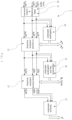
- Fig. 1 presents a general scheme of encoding 1 according to the invention.
- Encoding 1 is performed by the encoder.
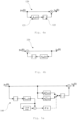
- Fig. 3 presents a general scheme of decoding 3 according to the invention, by reversing the operations performed during encoding 1 .
- Decoding 3 is performed by the decoder.
- the encoder and decoder may be a software solutions or a hardware solutions e.g. the ASIC or FPGA circuits.
- the encoder can be implemented in a portable electrocardiogram (ECG) data acquisition device.
- the decoder can be implemented in a central processing system, where the data from the patients is received and analyzed.
- Such portable electrocardiogram (ECG) data acquisition device, central processing system, and means for data transmission (e.g. wireless network, Bluetooth Low Energy) between them form a computer system to carry out the method according to the invention.
- the computer program to perform the method is implemented in this computer system.
- Encoding 1 starts with collecting input ECG signals x 1 (k),x 2 (k),...,x M (k). The signals are collected from M parallel channels.
- This prediction scheme is commonly known as a delta encoding 10. In result of delta encoding 10 the signal y m * k is obtained.
- the output signal y m * k of delta encoding 10 is on average smaller than its input - ECG signal x m (k), but in the event of abrupt change of baseline in the ECG, delta encoder produces a high-amplitude spike. Since signal is encoded using fixed-point representation, such amplitude increase must be handled to prevent 11 an overflow and data loss. Fortunately, these amplitude increases are rare, can be removed from the standard dataflow and treated as an additional delta encoding output.
- y m k ⁇ y m ⁇ k y m ⁇ k ⁇ Y max , 0 y m ⁇ k ⁇ Y max .
- the characteristics of other components of the ECG signal x m (k) i.e.: x m qrs k , x m emg k , x m bg k cannot be accurately predicted a priori and the statistical analysis must be performed on the given signal.
- the decorrelation of the ECG signal is divided into the in-channel predictive encoding 12 and the cross-channel predictive encoding 13 .
- the in-channel predictive encoding 12 the prediction relies on the previous samples of the same signal.
- the cross-channel predictive encoding 13 the prediction relies on the on the samples from the other signal.
- the output signal y m (k) of the delta encoding 10 is firstly subjected to the in-channel predictive encoding 12 .
- the predictive encoding is performed with the use of linear predictors.
- L lp is the length of the filter.
- the result is added to unfiltered signal y m (k).
- the output signal z m (k) is obtained.
- the characteristics of the heartbeat x m qrs k of the ECG signal x m (k) differs from the characteristics of the other components (electromyographic noise x m emg k and background noise x m bg k ). It is profitable to extract the heartbeat x m qrs k to perform its prediction separately.
- the present invention takes advantage of this and uses separate linear predictors for decorrelating heartbeats and background components of the signal y(k) during the in-channel predictive encoding 12 .
- Detection of heartbeats is performed with the use of detector of heartbeats and selective linear predictive encoder 140 which is presented in Fig. 5a . Notion “selective” indicates on switching between specialized predictors, for heartbeats and for background component of ECG signal.
- the heartbeats are detected with the use of a causal method which is based on the processing of a previous samples to decide whether currently processed samples contain an heartbeat.
- the criterion of distinguishing the heartbeat from the background relies on the comparison of the local signal's magnitude to the magnitude of the most recent extremum in last K norm samples, preceding the currently processed signal sample. In the absence of strong distortions and noise such an extremum usually corresponds to R-peak of heartbeat.
- the samples for which the ratio of the magnitudes exceeds the predefined threshold, are assumed to be the part containing the heartbeat.
- the decorrelation is performed using one of the predictors: A m ,i bg z for the background component or A m ,i qrs z or for the heartbeats.
- the detector of heartbeats and selective linear predictive decoder 340 which is used during decoding 3 is presented in Fig. 5b .
- the next step of the method according to the invention after the in-channel predictive encoding 12 is the cross-channel predictive encoding 13 . Since the useful signal usually dominates over the background noise, then a substantial correlation between channels can be expected.
- the method according to the invention uses one channel to predict the values of the other one, so to optimize the choice of channel pairs and to maximize the number of channels benefiting from the prediction, the method arranges these pairs of channels into a tree of dependencies, such that one channel is used for prediction of the other channels, and the predicted channels are used for prediction of further channels.
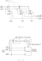
- the scheme of the cross-channel predictive encoding 13 block is presented in Fig 6a . Signals from each channel are fed into cross-channel predictive encoders 130 and also into set of multiplexers for multiplexing.
- signals from the output of the multiplexing are fed into cross-channel predictive encoders 130 as a reference signals.
- cross-channel prediction encoding 13 signal v m (k) is obtained.
- the cross-channel prediction encoding 22 is linear.
- the cross-channel predictive encoder 130 is presented in fig. 7a .
- the input signal z m (k) is decorrelated with the use of a decorrelating signal z n (k).
- the decorrelating signal z n (k) is filtered 131 with the use of filter B m,i (z) and transformed 132 to integers.
- the choice of decorrelating signal z n (k) is determined during multiplexing.
- the result is added to signal z m (k).
- the output signal v m (k) is obtained.
- the next step of the method according to the invention is the entropy coding 14 with the use of variance of a prediction error.
- the entropy coding 14 is based on the principle of assigning the short codes to the more probable symbols and the longer codes to the less probable ones.
- the entropy coding 14 of a prediction error is performed with the use of any state-of-art method, which allows the arbitrary choice of a probability distribution of symbol occurrence, for example Asymmetric Numeral Systems method (ANS).
- the result of encoding signal v m (k) in the i-th block is a number C m,i .
- the final step of encoding according to the invention is multiplexing 15 .
- multiplexer combines together multiple entropy encoded signals c 1,i ,c 2,i ,...,c M,i from M channels, and outliers Y i ⁇ , K i , into one encoded datastream.
- estimated parameters A 1 qrs , A 1 bg , B 1 , N 1 (m), ⁇ 1 2 are included.
- This encoded data is sent as a bitstream further to a decoder.
- Fig. 3 presents a general scheme of decoding 3 according to the invention.
- Decoding 3 starts with collecting bitstream and demultiplexing 30 it into entropy encoded signals c 1,i , c 2,i , ..., c M,i , outliers Y i ⁇ , K i , and for the first frame also parameters A 1 qrs , A 1 bg , B 1 , N 1 (m), ⁇ 1 2 .
- Next step of the method is entropy decoding 31 with the use of variance of a prediction error.
- the entropy decoding is performed by the decoder complementary with entropy encoder 14 , and the result of decoding of the signal c m,i is signal v m (k) for i-th block.
- the cross-channel linear predictive decoding 32 of signal v m (k) back into signal z m (k), is presented in Fig. 6b . It consists in reversing the operation performed by cross-channel linear predictive encoding 13 , presented in Fig. 6a .
- the cross-channel predictive decoding 33 uses the cross-channel predictive decoders 330 .
- the cross-channel predictive decoders 330 are shown in Fig. 7b .
- the in-channel linear predictive decoding 33 of signal z m (k) back into signal y m (k) consists in reversing the operation performed by in-channel linear predictive encoding 12 .
- the in-channel predictive decoding 33 uses the in-channel predictive decoders 320, presented in Fig. 4b .
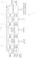
- the process of the compression and decompression of the electrocardiogram signal x m (k), described in details above, has to be preceded by a predictors training 2 .
- Predictors training 2 is performed by the encoder and decoder.
- the encoder and decoder may be a software solutions or a hardware solutions e.g. the ASIC or FPGA circuits.
- the encoder can be implemented in a portable electrocardiogram (ECG) data acquisition device.
- ECG electrocardiogram
- the decoder can be implemented in a central processing system, where the data from the patients is received and analyzed.
- Block diagram of the predictors training 2 is presented in Fig. 2 and the steps of the prediction training 2 are presented chronologically in fig. 10 .
- the signal y m (k) from each channel, after delta encoding 20 and overflow prevention 21 is decorrelated.
- the decorrelation is divided into in-channel predictive encoding 22 and cross-channel predictive encoding 23 .
- the signal y m (k) from each channel, after delta encoding 20 and overflow prevention 21 is divided into heartbeats and background in the block in-channel predictive encoding block.
- the signal y m,i (k) is the part of the signal y m (k) used for the training of the predictor A m,i (z), which is further applied for decorrelation of signal during i -th block of signal.
- K lp and L lp are respectively the length of linear predictor training sequence and the length of the predictor a m,i .
- the Yule-Walker equations can be solved efficiently with complexity O L lp 2 using the Levinson-Durbin method.
- the in-channel predictive encoding 22 is performed and resulting signals z 1 ⁇ k , ... , z M ⁇ k are fed to the cross-channel predictive encoding block.
- the cross-channel predictive encoding 23 the cross-channel correlation R (i),xc is estimated and tree of dependency N i (m) is determined 25 .
- R m ,m i a m ,i ⁇ r m ,m i
- the signals z m,i (k) and z n,i (k) are respectively parts of the signals z m (k) and z n (k) used for the training of the predictor B m,i (z), which is further applied for decorrelation of signal during i -th block.
- N i (n 1 ) n 2
- n 2 cannot be used for prediction of n 1 (N i (n 2 ) ⁇ n 1 ).
- N i (m) N i ⁇ N i ⁇ ⁇ ⁇ N i m ⁇ m .
- the method according to the invention proposes determining suboptimal assignment N i (m) based on verifying the dependence between channels using the cross-channel correlation and determining the base channel n 0 .
- N i max m ⁇ m with the highest correlation is found.
- N i max m : argmax n ⁇ ⁇ 1 , ... , M ⁇ m R n ⁇ , m i , xc
- step 2) is performed.
- predictors training 2 is performed periodically to avoid mismatch between the characteristics of the signal.
- Predictors training 2 in the encoder takes place in parallel with encoding 1 , during the final part of each signal block.
- Predictors training 2 is finalized at the end of block, the compression parameters A i qrs , A i bg , B i , N i (m) and ⁇ i 2 are latched in the memory, as shown in Fig. 9a , and used for encoding 1 of the next signal block.
- Predictors training 2 in the decoder 3 takes place after the signal from the previous block is decoded.
- the prediction parameters A i qrs , A i bg , B i , N i (m), ⁇ i 2 has to be sent to decoder only along with the first block, since the parameters of the latter blocks can be estimated on the decoder's side using already decoded signal, as shown in Fig. 9b .
- the invention relates also to a computer program to carry out the method.
- the computer program is dedicated to be implemented in a low-power ECG portable device designed for acquisition of an ECG signal and sending it further to a decoder.
Landscapes
- Engineering & Computer Science (AREA)
- Theoretical Computer Science (AREA)
- Measurement And Recording Of Electrical Phenomena And Electrical Characteristics Of The Living Body (AREA)
- Compression, Expansion, Code Conversion, And Decoders (AREA)
Priority Applications (2)
| Application Number | Priority Date | Filing Date | Title |
|---|---|---|---|
| PL19460036.7T PL3764548T3 (pl) | 2019-07-09 | 2019-07-09 | Sposób, program komputerowy i system komputerowy do bezstratnej kompresji wielokanałowego sygnału elektrokardiogramu |
| EP19460036.7A EP3764548B1 (en) | 2019-07-09 | 2019-07-09 | Method, computer program, and computer system for lossless compression of a multichannel electrocardiogram signal |
Applications Claiming Priority (1)
| Application Number | Priority Date | Filing Date | Title |
|---|---|---|---|
| EP19460036.7A EP3764548B1 (en) | 2019-07-09 | 2019-07-09 | Method, computer program, and computer system for lossless compression of a multichannel electrocardiogram signal |
Publications (3)
| Publication Number | Publication Date |
|---|---|
| EP3764548A1 EP3764548A1 (en) | 2021-01-13 |
| EP3764548C0 EP3764548C0 (en) | 2023-08-23 |
| EP3764548B1 true EP3764548B1 (en) | 2023-08-23 |
Family
ID=67439156
Family Applications (1)
| Application Number | Title | Priority Date | Filing Date |
|---|---|---|---|
| EP19460036.7A Active EP3764548B1 (en) | 2019-07-09 | 2019-07-09 | Method, computer program, and computer system for lossless compression of a multichannel electrocardiogram signal |
Country Status (2)
| Country | Link |
|---|---|
| EP (1) | EP3764548B1 (pl) |
| PL (1) | PL3764548T3 (pl) |
Families Citing this family (3)
| Publication number | Priority date | Publication date | Assignee | Title |
|---|---|---|---|---|
| CN114969637B (zh) * | 2022-04-18 | 2025-09-05 | 华南理工大学 | 基于线性预测的膈肌肌电实时处理方法及存储介质 |
| CN118633948A (zh) * | 2024-07-02 | 2024-09-13 | 西南医科大学 | 一种心电图无线采集分析系统 |
| CN120074539B (zh) * | 2025-04-29 | 2025-07-22 | 湖南科技大学 | 一种基于混合压缩算法的数据压缩方法及系统 |
Family Cites Families (3)
| Publication number | Priority date | Publication date | Assignee | Title |
|---|---|---|---|---|
| WO2004056120A1 (en) | 2002-12-17 | 2004-07-01 | Let It Wave | Processing or compressing n-dimensional signals with warped wavelet packets and bandelets |
| EP1995685A3 (en) * | 2007-05-21 | 2012-08-01 | Biotronik CRM Patent AG | Medical device for monitoring biological signal |
| TWI494081B (zh) | 2012-03-16 | 2015-08-01 | Univ Nat Cheng Kung | 心電圖訊號壓縮系統及解壓縮系統 |
-
2019
- 2019-07-09 PL PL19460036.7T patent/PL3764548T3/pl unknown
- 2019-07-09 EP EP19460036.7A patent/EP3764548B1/en active Active
Also Published As
| Publication number | Publication date |
|---|---|
| EP3764548C0 (en) | 2023-08-23 |
| PL3764548T3 (pl) | 2024-02-05 |
| EP3764548A1 (en) | 2021-01-13 |
Similar Documents
| Publication | Publication Date | Title |
|---|---|---|
| US12268527B2 (en) | System and method for automated analysis and detection of cardiac arrhythmias from electrocardiograms | |
| Sharma et al. | Multichannel ECG data compression based on multiscale principal component analysis | |
| Fira et al. | An ECG signals compression method and its validation using NNs | |
| EP3764548B1 (en) | Method, computer program, and computer system for lossless compression of a multichannel electrocardiogram signal | |
| KR101454790B1 (ko) | 템플릿 기반 심전도 신호 압축 및 복원 방법 | |
| Rzepka | Low-complexity lossless multichannel ECG compression based on selective linear prediction | |
| Kumar et al. | Electrocardiogram signal compression based on 2D-transforms: a research overview | |
| KR101029108B1 (ko) | 생체신호관리시스템에서의 심전도 데이터 압축 및 압축 해제 방법 | |
| Kumar Jha et al. | Diagnostic quality assured ECG signal compression with selection of appropriate mother wavelet for minimal distortion | |
| Nasimi et al. | Exploiting similar prior knowledge for compressing ECG signals | |
| Alesanco et al. | A novel real-time multilead ECG compression and de-noising method based on the wavelet transform | |
| Sharma et al. | Ecg compression based on empirical mode decomposition and tunable-q wavelet transform with validation using heartbeat classification | |
| Tanasković et al. | A new algorithm for fetal heart rate detection: Fractional order calculus approach | |
| Liu et al. | Studying the effects of compression in EEG-based wearable sleep monitoring systems | |
| KR20090089039A (ko) | 주기성을 갖는 생체 신호 데이터의 실시간 압축 전송 및저장 방법과 이를 위한 심혈관 시스템 | |
| Pal et al. | TQWT based electrocardiogram compression using optimized thresholding | |
| Gupta et al. | Pre-processing of ECG signal based on ANF and ICA: a comparison | |
| CN110874879A (zh) | 基于语音识别的老人挂号方法、装置、设备及存储介质 | |
| Joshi | Fundamentals of Electrocardiografia (ECG) With Arduino Uno | |
| CN113143284B (zh) | 基于小波变换和双模预测的心电信号压缩方法 | |
| Eddie Filho et al. | On ECG signal compression with 1-D multiscale recurrent patterns allied to preprocessing techniques | |
| Abo-Zahhad et al. | ECG signal compression technique based on DWT and exploitation of interbeats and intrabeats correlations | |
| Singh et al. | Compressed sensing framework of data reduction at multiscale level for eigenspace multichannel ECG signals | |
| Sharma et al. | Electrocardiography signal compression using non-decimated stationary wavelet transform-based technique | |
| Ding et al. | ECG compression for mobile sensor platforms |
Legal Events
| Date | Code | Title | Description |
|---|---|---|---|
| PUAI | Public reference made under article 153(3) epc to a published international application that has entered the european phase |
Free format text: ORIGINAL CODE: 0009012 |
|
| STAA | Information on the status of an ep patent application or granted ep patent |
Free format text: STATUS: THE APPLICATION HAS BEEN PUBLISHED |
|
| AK | Designated contracting states |
Kind code of ref document: A1 Designated state(s): AL AT BE BG CH CY CZ DE DK EE ES FI FR GB GR HR HU IE IS IT LI LT LU LV MC MK MT NL NO PL PT RO RS SE SI SK SM TR |
|
| AX | Request for extension of the european patent |
Extension state: BA ME |
|
| STAA | Information on the status of an ep patent application or granted ep patent |
Free format text: STATUS: REQUEST FOR EXAMINATION WAS MADE |
|
| 17P | Request for examination filed |
Effective date: 20210709 |
|
| RBV | Designated contracting states (corrected) |
Designated state(s): AL AT BE BG CH CY CZ DE DK EE ES FI FR GB GR HR HU IE IS IT LI LT LU LV MC MK MT NL NO PL PT RO RS SE SI SK SM TR |
|
| GRAP | Despatch of communication of intention to grant a patent |
Free format text: ORIGINAL CODE: EPIDOSNIGR1 |
|
| STAA | Information on the status of an ep patent application or granted ep patent |
Free format text: STATUS: GRANT OF PATENT IS INTENDED |
|
| INTG | Intention to grant announced |
Effective date: 20230215 |
|
| GRAS | Grant fee paid |
Free format text: ORIGINAL CODE: EPIDOSNIGR3 |
|
| GRAA | (expected) grant |
Free format text: ORIGINAL CODE: 0009210 |
|
| STAA | Information on the status of an ep patent application or granted ep patent |
Free format text: STATUS: THE PATENT HAS BEEN GRANTED |
|
| AK | Designated contracting states |
Kind code of ref document: B1 Designated state(s): AL AT BE BG CH CY CZ DE DK EE ES FI FR GB GR HR HU IE IS IT LI LT LU LV MC MK MT NL NO PL PT RO RS SE SI SK SM TR |
|
| REG | Reference to a national code |
Ref country code: GB Ref legal event code: FG4D |
|
| REG | Reference to a national code |
Ref country code: CH Ref legal event code: EP |
|
| REG | Reference to a national code |
Ref country code: DE Ref legal event code: R096 Ref document number: 602019035529 Country of ref document: DE |
|
| REG | Reference to a national code |
Ref country code: IE Ref legal event code: FG4D |
|
| U01 | Request for unitary effect filed |
Effective date: 20230920 |
|
| U07 | Unitary effect registered |
Designated state(s): AT BE BG DE DK EE FI FR IT LT LU LV MT NL PT SE SI Effective date: 20230928 |
|
| PG25 | Lapsed in a contracting state [announced via postgrant information from national office to epo] |
Ref country code: GR Free format text: LAPSE BECAUSE OF FAILURE TO SUBMIT A TRANSLATION OF THE DESCRIPTION OR TO PAY THE FEE WITHIN THE PRESCRIBED TIME-LIMIT Effective date: 20231124 |
|
| PG25 | Lapsed in a contracting state [announced via postgrant information from national office to epo] |
Ref country code: IS Free format text: LAPSE BECAUSE OF FAILURE TO SUBMIT A TRANSLATION OF THE DESCRIPTION OR TO PAY THE FEE WITHIN THE PRESCRIBED TIME-LIMIT Effective date: 20231223 |
|
| PG25 | Lapsed in a contracting state [announced via postgrant information from national office to epo] |
Ref country code: RS Free format text: LAPSE BECAUSE OF FAILURE TO SUBMIT A TRANSLATION OF THE DESCRIPTION OR TO PAY THE FEE WITHIN THE PRESCRIBED TIME-LIMIT Effective date: 20230823 Ref country code: NO Free format text: LAPSE BECAUSE OF FAILURE TO SUBMIT A TRANSLATION OF THE DESCRIPTION OR TO PAY THE FEE WITHIN THE PRESCRIBED TIME-LIMIT Effective date: 20231123 Ref country code: IS Free format text: LAPSE BECAUSE OF FAILURE TO SUBMIT A TRANSLATION OF THE DESCRIPTION OR TO PAY THE FEE WITHIN THE PRESCRIBED TIME-LIMIT Effective date: 20231223 Ref country code: HR Free format text: LAPSE BECAUSE OF FAILURE TO SUBMIT A TRANSLATION OF THE DESCRIPTION OR TO PAY THE FEE WITHIN THE PRESCRIBED TIME-LIMIT Effective date: 20230823 Ref country code: GR Free format text: LAPSE BECAUSE OF FAILURE TO SUBMIT A TRANSLATION OF THE DESCRIPTION OR TO PAY THE FEE WITHIN THE PRESCRIBED TIME-LIMIT Effective date: 20231124 |
|
| PG25 | Lapsed in a contracting state [announced via postgrant information from national office to epo] |
Ref country code: ES Free format text: LAPSE BECAUSE OF FAILURE TO SUBMIT A TRANSLATION OF THE DESCRIPTION OR TO PAY THE FEE WITHIN THE PRESCRIBED TIME-LIMIT Effective date: 20230823 |
|
| PG25 | Lapsed in a contracting state [announced via postgrant information from national office to epo] |
Ref country code: SM Free format text: LAPSE BECAUSE OF FAILURE TO SUBMIT A TRANSLATION OF THE DESCRIPTION OR TO PAY THE FEE WITHIN THE PRESCRIBED TIME-LIMIT Effective date: 20230823 Ref country code: RO Free format text: LAPSE BECAUSE OF FAILURE TO SUBMIT A TRANSLATION OF THE DESCRIPTION OR TO PAY THE FEE WITHIN THE PRESCRIBED TIME-LIMIT Effective date: 20230823 Ref country code: ES Free format text: LAPSE BECAUSE OF FAILURE TO SUBMIT A TRANSLATION OF THE DESCRIPTION OR TO PAY THE FEE WITHIN THE PRESCRIBED TIME-LIMIT Effective date: 20230823 Ref country code: CZ Free format text: LAPSE BECAUSE OF FAILURE TO SUBMIT A TRANSLATION OF THE DESCRIPTION OR TO PAY THE FEE WITHIN THE PRESCRIBED TIME-LIMIT Effective date: 20230823 Ref country code: SK Free format text: LAPSE BECAUSE OF FAILURE TO SUBMIT A TRANSLATION OF THE DESCRIPTION OR TO PAY THE FEE WITHIN THE PRESCRIBED TIME-LIMIT Effective date: 20230823 |
|
| REG | Reference to a national code |
Ref country code: DE Ref legal event code: R097 Ref document number: 602019035529 Country of ref document: DE |
|
| PLBE | No opposition filed within time limit |
Free format text: ORIGINAL CODE: 0009261 |
|
| STAA | Information on the status of an ep patent application or granted ep patent |
Free format text: STATUS: NO OPPOSITION FILED WITHIN TIME LIMIT |
|
| 26N | No opposition filed |
Effective date: 20240524 |
|
| U20 | Renewal fee for the european patent with unitary effect paid |
Year of fee payment: 6 Effective date: 20240717 |
|
| PGFP | Annual fee paid to national office [announced via postgrant information from national office to epo] |
Ref country code: PL Payment date: 20240708 Year of fee payment: 6 |
|
| U1N | Appointed representative for the unitary patent procedure changed after the registration of the unitary effect |
Representative=s name: KURDUBSKI, DANIEL; PL |
|
| PGFP | Annual fee paid to national office [announced via postgrant information from national office to epo] |
Ref country code: GB Payment date: 20241008 Year of fee payment: 6 |
|
| PG25 | Lapsed in a contracting state [announced via postgrant information from national office to epo] |
Ref country code: MC Free format text: LAPSE BECAUSE OF FAILURE TO SUBMIT A TRANSLATION OF THE DESCRIPTION OR TO PAY THE FEE WITHIN THE PRESCRIBED TIME-LIMIT Effective date: 20230823 |
|
| REG | Reference to a national code |
Ref country code: CH Ref legal event code: PL |
|
| PG25 | Lapsed in a contracting state [announced via postgrant information from national office to epo] |
Ref country code: CH Free format text: LAPSE BECAUSE OF NON-PAYMENT OF DUE FEES Effective date: 20240731 |
|
| PG25 | Lapsed in a contracting state [announced via postgrant information from national office to epo] |
Ref country code: IE Free format text: LAPSE BECAUSE OF NON-PAYMENT OF DUE FEES Effective date: 20240709 |
|
| PG25 | Lapsed in a contracting state [announced via postgrant information from national office to epo] |
Ref country code: CY Free format text: LAPSE BECAUSE OF FAILURE TO SUBMIT A TRANSLATION OF THE DESCRIPTION OR TO PAY THE FEE WITHIN THE PRESCRIBED TIME-LIMIT; INVALID AB INITIO Effective date: 20190709 |
|
| PG25 | Lapsed in a contracting state [announced via postgrant information from national office to epo] |
Ref country code: HU Free format text: LAPSE BECAUSE OF FAILURE TO SUBMIT A TRANSLATION OF THE DESCRIPTION OR TO PAY THE FEE WITHIN THE PRESCRIBED TIME-LIMIT; INVALID AB INITIO Effective date: 20190709 |
|
| GBPC | Gb: european patent ceased through non-payment of renewal fee |
Effective date: 20250709 |
|
| U90 | Renewal fees not paid: noting of loss of rights |
Free format text: RENEWAL FEE NOT PAID FOR YEAR 07 Effective date: 20260224 |