EP3764516A1 - On-vehicle brushless motor device and method of manufacturing the same - Google Patents
On-vehicle brushless motor device and method of manufacturing the same Download PDFInfo
- Publication number
- EP3764516A1 EP3764516A1 EP20180771.6A EP20180771A EP3764516A1 EP 3764516 A1 EP3764516 A1 EP 3764516A1 EP 20180771 A EP20180771 A EP 20180771A EP 3764516 A1 EP3764516 A1 EP 3764516A1
- Authority
- EP
- European Patent Office
- Prior art keywords
- brushless motor
- terminal
- rotor
- motor device
- substrate
- Prior art date
- Legal status (The legal status is an assumption and is not a legal conclusion. Google has not performed a legal analysis and makes no representation as to the accuracy of the status listed.)
- Granted
Links
Images









Classifications
-
- H—ELECTRICITY
- H02—GENERATION; CONVERSION OR DISTRIBUTION OF ELECTRIC POWER
- H02K—DYNAMO-ELECTRIC MACHINES
- H02K3/00—Details of windings
- H02K3/46—Fastening of windings on the stator or rotor structure
- H02K3/52—Fastening salient pole windings or connections thereto
- H02K3/521—Fastening salient pole windings or connections thereto applicable to stators only
- H02K3/522—Fastening salient pole windings or connections thereto applicable to stators only for generally annular cores with salient poles
-
- H—ELECTRICITY
- H02—GENERATION; CONVERSION OR DISTRIBUTION OF ELECTRIC POWER
- H02K—DYNAMO-ELECTRIC MACHINES
- H02K3/00—Details of windings
- H02K3/46—Fastening of windings on the stator or rotor structure
- H02K3/50—Fastening of winding heads, equalising connectors, or connections thereto
-
- F—MECHANICAL ENGINEERING; LIGHTING; HEATING; WEAPONS; BLASTING
- F04—POSITIVE - DISPLACEMENT MACHINES FOR LIQUIDS; PUMPS FOR LIQUIDS OR ELASTIC FLUIDS
- F04D—NON-POSITIVE-DISPLACEMENT PUMPS
- F04D13/00—Pumping installations or systems
- F04D13/02—Units comprising pumps and their driving means
- F04D13/06—Units comprising pumps and their driving means the pump being electrically driven
-
- H—ELECTRICITY
- H02—GENERATION; CONVERSION OR DISTRIBUTION OF ELECTRIC POWER
- H02K—DYNAMO-ELECTRIC MACHINES
- H02K11/00—Structural association of dynamo-electric machines with electric components or with devices for shielding, monitoring or protection
- H02K11/30—Structural association with control circuits or drive circuits
- H02K11/33—Drive circuits, e.g. power electronics
-
- H—ELECTRICITY
- H02—GENERATION; CONVERSION OR DISTRIBUTION OF ELECTRIC POWER
- H02K—DYNAMO-ELECTRIC MACHINES
- H02K15/00—Processes or apparatus specially adapted for manufacturing, assembling, maintaining or repairing of dynamo-electric machines
- H02K15/30—Manufacture of winding connections
- H02K15/32—Manufacture of terminal arrangements; Connecting the terminals to external circuits
-
- H—ELECTRICITY
- H02—GENERATION; CONVERSION OR DISTRIBUTION OF ELECTRIC POWER
- H02K—DYNAMO-ELECTRIC MACHINES
- H02K21/00—Synchronous motors having permanent magnets; Synchronous generators having permanent magnets
- H02K21/12—Synchronous motors having permanent magnets; Synchronous generators having permanent magnets with stationary armatures and rotating magnets
- H02K21/14—Synchronous motors having permanent magnets; Synchronous generators having permanent magnets with stationary armatures and rotating magnets with magnets rotating within the armatures
- H02K21/16—Synchronous motors having permanent magnets; Synchronous generators having permanent magnets with stationary armatures and rotating magnets with magnets rotating within the armatures having annular armature cores with salient poles
-
- H—ELECTRICITY
- H02—GENERATION; CONVERSION OR DISTRIBUTION OF ELECTRIC POWER
- H02K—DYNAMO-ELECTRIC MACHINES
- H02K29/00—Motors or generators having non-mechanical commutating devices, e.g. discharge tubes or semiconductor devices
-
- H—ELECTRICITY
- H01—ELECTRIC ELEMENTS
- H01R—ELECTRICALLY-CONDUCTIVE CONNECTIONS; STRUCTURAL ASSOCIATIONS OF A PLURALITY OF MUTUALLY-INSULATED ELECTRICAL CONNECTING ELEMENTS; COUPLING DEVICES; CURRENT COLLECTORS
- H01R12/00—Structural associations of a plurality of mutually-insulated electrical connecting elements, specially adapted for printed circuits, e.g. printed circuit boards [PCB], flat or ribbon cables, or like generally planar structures, e.g. terminal strips, terminal blocks; Coupling devices specially adapted for printed circuits, flat or ribbon cables, or like generally planar structures; Terminals specially adapted for contact with, or insertion into, printed circuits, flat or ribbon cables, or like generally planar structures
- H01R12/50—Fixed connections
- H01R12/51—Fixed connections for rigid printed circuits or like structures
- H01R12/53—Fixed connections for rigid printed circuits or like structures connecting to cables except for flat or ribbon cables
-
- H—ELECTRICITY
- H01—ELECTRIC ELEMENTS
- H01R—ELECTRICALLY-CONDUCTIVE CONNECTIONS; STRUCTURAL ASSOCIATIONS OF A PLURALITY OF MUTUALLY-INSULATED ELECTRICAL CONNECTING ELEMENTS; COUPLING DEVICES; CURRENT COLLECTORS
- H01R4/00—Electrically-conductive connections between two or more conductive members in direct contact, i.e. touching one another; Means for effecting or maintaining such contact; Electrically-conductive connections having two or more spaced connecting locations for conductors and using contact members penetrating insulation
- H01R4/02—Soldered or welded connections
- H01R4/023—Soldered or welded connections between cables or wires and terminals
-
- H—ELECTRICITY
- H01—ELECTRIC ELEMENTS
- H01R—ELECTRICALLY-CONDUCTIVE CONNECTIONS; STRUCTURAL ASSOCIATIONS OF A PLURALITY OF MUTUALLY-INSULATED ELECTRICAL CONNECTING ELEMENTS; COUPLING DEVICES; CURRENT COLLECTORS
- H01R4/00—Electrically-conductive connections between two or more conductive members in direct contact, i.e. touching one another; Means for effecting or maintaining such contact; Electrically-conductive connections having two or more spaced connecting locations for conductors and using contact members penetrating insulation
- H01R4/02—Soldered or welded connections
- H01R4/029—Welded connections
-
- H—ELECTRICITY
- H02—GENERATION; CONVERSION OR DISTRIBUTION OF ELECTRIC POWER
- H02K—DYNAMO-ELECTRIC MACHINES
- H02K2203/00—Specific aspects not provided for in the other groups of this subclass relating to the windings
- H02K2203/03—Machines characterised by the wiring boards, i.e. printed circuit boards or similar structures for connecting the winding terminations
Definitions
- an expression of an equal state such as “same”, “equal” and “uniform” shall not be construed as indicating only the state in which the feature is strictly equal, but also includes a state in which there is a tolerance or a difference that can still achieve the same function.
- the distance along the surface of the terminal 40 from the protruding portion 80 to the first soldering portion 90 (the length along the arrow K in FIG. 3 ) can be increased while suppressing an increase in the size of the terminal 40. Therefore, it is possible to suppress the heat of welding from being transmitted from the protruding portion 80 to the first soldering portion 90 at the time of fusion welding of the protruding portion 80 and the coil wire 20, and to suppress remelting of the first soldering portion 90. Therefore, it is possible to realize an excellent electrical connection state between the electronic substrate 30 and the coil 18 while suppressing an increase in size of the on-vehicle brushless motor device 1.
- FIG. 6 is a plan view schematically illustrating a configuration example of the terminal 40 illustrated in FIG. 3 .
- the diameter D2 of the substrate-side opening end 56 (the inner diameter of the substrate-side opening end 56) may be smaller than the diameter D1 of the through hole 34.
- the coil wire 20 having passed through the substrate-side opening end 56 may be more easily and smoothly guided to the through hole 34 of the electronic substrate 30.
- the "diameter of the substrate-side opening end 56" means the hole diameter (passage diameter) of the guide hole 54 at the position of the substrate-side opening end 56.
- the method of manufacturing the on-vehicle brushless motor device 1 includes step S1 of arranging the substrate body 32 of the electronic substrate 30 along a plane P intersecting the axial direction X on the side opposite to the output side of the brushless motor 10, step S2 of passing the coil wire 20 of the coil 18 constituting the stator 16 of the brushless motor 10 through the through hole 34 of the electronic substrate 30, and step S3 of welding the coil wire 20 to the hook portion 80b of the terminal 40 fixed on the surface 32A of the substrate body 32 opposite to the rotor 12 with respect to the electronic substrate 30.
Landscapes
- Engineering & Computer Science (AREA)
- Power Engineering (AREA)
- Manufacturing & Machinery (AREA)
- Mechanical Engineering (AREA)
- General Engineering & Computer Science (AREA)
- Microelectronics & Electronic Packaging (AREA)
- Motor Or Generator Frames (AREA)
- Insulation, Fastening Of Motor, Generator Windings (AREA)
- Manufacture Of Motors, Generators (AREA)
Abstract
Description
- The present disclosure relates to a brushless motor device mounted on a vehicle (hereinafter, called an on-vehicle brushless motor device) and a method of manufacturing the same.
- In recent years, various brushless motors have been developed which do not use mechanical contacts such as brushes and commutators. For example,
Patent Document 1 discloses a configuration related to a pump device including a brushless motor. - Patent Document 1: Japanese Patent Application Laid-open No.
2017-15002 - By the way, an electric actuator to be mounted on a vehicle is desired to be miniaturized due to limitation of a space for mounting the electric actuator. However, in the pump device described in
Patent Document 1, a driving coil and a circuit board are connected to each other through a terminal pin arranged along an axial direction of a rotor by soldering one end of the terminal pin having the other end electrically connected to the driving coil to the circuit board. Therefore, in the axial direction of the rotor, it is required to secure a space for soldering the terminal pin to the circuit board in addition to a space for arranging the terminal pin. Thus, it is difficult to reduce the size of the entire pump device in the axial direction of the rotor.Patent Document 1 does not disclose any solution for solving such a problem. - In view of the foregoing, it is an object of at least one embodiment of the present disclosure to provide an on-vehicle brushless motor device that can be miniaturized in the axial direction of the rotor and a method of manufacturing the same.
- (1) An on-vehicle brushless motor device according to at least one embodiment of the present invention includes a brushless motor including a rotor and a stator which include a plurality of coils arranged around the rotor; and an electronic substrate including a substrate body provided with a through hole penetrating in the axial direction of the rotor and arranged along a plane intersecting the axial direction on the side opposite to the output side of the brushless motor, and a terminal fixed on a surface of the substrate body opposite to the rotor. Here, a coil wire of the coil is inserted through the through hole and welded to the terminal on a side opposite to the rotor with respect to the substrate body.
- (2) In some embodiments, in the configuration described above as (1), a first slit extending along a first direction included in the plane may be formed in the terminal, the terminal may include a first terminal portion provided on one side and a second terminal portion provided on the other side with the first slit interposed therebetween, a third terminal portion connecting the first terminal portion and the second terminal portion, and a protruding portion provided to protrude from the second terminal portion to the opposite side to the rotor in the axial direction, the protruding portion may be welded to the coil wire, and the first terminal portion may be connected to the substrate body via a first soldering portion.
- (3) In some embodiments, in the configuration described above as (2), the second terminal portion may be connected to the substrate body via a second soldering portion, and the first soldering portion and the second soldering portion may be separated from each other.
- (4) In some embodiments, in the configuration described above as (2) or (3), the third terminal portion may be connected to one end portion of the second terminal portion in the first direction, and the protruding portion may be connected to the other end portion of the second terminal portion in the first direction.
- (5) In some embodiments, in the configuration described above as any one of (2) to (4), the protruding portion may include a hook portion formed in a hook shape and welded to the coil wire by fusing.
- (6) In some embodiments, in the configuration described above as any one of (2) to (5), the length of the second terminal portion in the first direction may be longer than the length of the first terminal portion in the first direction.
- (7) In some embodiments, in the configuration described above as (3), the electronic substrate may include a metal foil terminal portion arranged adjacent to the through hole and disposed along a surface of the substrate body opposite to the rotor, and a resist disposed on the metal foil terminal portion and including a first opening corresponding to the first soldering portion and a second opening corresponding to the second soldering portion, a second slit extending in the first direction may be formed in the metal foil terminal portion, and the metal foil terminal portion may include a first portion provided on one side and a second portion provided on the other side with the second slit interposed therebetween, and a third portion connecting the first portion and the second portion. Here, the first portion may be connected to the first soldering portion in the first opening and second portion being connected to the second soldering portion in the second opening.
- (8) In some embodiments, in the configuration described above as (7), an area of the second portion may be larger than an area of the first portion.
- (9) In some embodiments, in the configuration described above as (8), the area of the second portion may be 1.2 times or more the area of the first portion.
- (10) In some embodiments, in the configuration described above as any one of (1) to (9), the electronic substrate may include a plurality of the terminals, and the terminals may be oriented in the same direction with respect to the substrate body.
- (11) In some embodiments, in the configuration described above as any one of (1) to (10), the on-vehicle brushless motor device may further include a holder unit including a connector terminal for connecting the electronic substrate and an external device and a holder disposed between the substrate body and the brushless motor to support the electronic board, and the electronic substrate may include a third soldering portion for being connected to the connector terminal.
- (12) In some embodiments, in the configuration described above as (11), the holder may include a guide hole penetrating the holder in the axial direction and guiding the coil wire from the brushless motor side to the through hole of the substrate body.
- (13) In some embodiments, in the configuration described above as (12), the guide hole may include a tapered passage portion formed such that a hole diameter decreases as a distance from the rotor in the axial direction increases.
- (14) In some embodiments, in the configuration described above as (12) or (13), the diameter of an opening end of the guide hole on the electronic substrate side may be smaller than the diameter of the through hole.
- (15) A method of manufacturing an on-vehicle brushless motor device according to at least one embodiment of the present invention includes steps of arranging a substrate body of an electronic substrate on a side opposite to an output side of a brushless motor along a plane intersecting an axial direction of a rotor of the brushless motor, passing a coil wire of a coil constituting a stator of the brushless motor through a through hole of the electronic substrate, and welding the coil wire to a terminal fixed on a surface of the substrate body opposite to the rotor on a side opposite to the rotor with respect to the electronic substrate.
- According to at least one embodiment of the present disclosure, it is possible to provide an on-vehicle brushless motor device which can be miniaturized in the axial direction of the rotor and a method of manufacturing the same.
-
-
FIG. 1 is a view schematically illustrating a configuration example of an on-vehicle brushless motor device according to an embodiment of the present disclosure. -
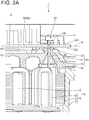
FIG. 2A is a partial enlarged view illustrating a region II indicated by a broken line inFIG. 1 . -
FIG. 2B is a view illustrating an example of arrangement of magnets. -
FIG. 3 is a top view illustrating a configuration example of a terminal according to an embodiment. -
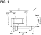
FIG. 4 is a side view illustrating a configuration example of a terminal according to an embodiment. -
FIG. 5 is a bottom view illustrating a configuration example of a terminal according to an embodiment. -
FIG. 6 is a plan view schematically illustrating a configuration example of a terminal according to an embodiment. -
FIG. 7 is a perspective view schematically illustrating a metal foil terminal portion according to an embodiment. -
FIG. 8 is a perspective view schematically illustrating a first opening and a second opening of a resist according to an embodiment. -
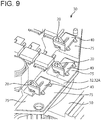
FIG. 9 is a perspective view schematically illustrating a state in which a terminal according to an embodiment is mounted on a substrate body. -
FIG. 10 is a plan view schematically illustrating a configuration example of a metal foil terminal portion according to an embodiment. -
FIG. 11 is a plan view schematically illustrating a region above an electronic substrate according to an embodiment. -
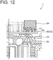
FIG. 12 is a side view schematically illustrating a region above an electronic substrate according to an embodiment. -
FIG. 13 is a schematic view schematically illustrating a guide hole according to an embodiment. -
FIG. 14 is a view illustrating a modification of the guide hole according to the embodiment. -
FIG. 15 is a flowchart illustrating a method of manufacturing an on-vehicle brushless motor device according to an embodiment. - Embodiments of the present invention will now be described in detail with reference to the accompanying drawings. It is intended, however, that unless particularly specified, dimensions, materials, shapes, relative positions and the like of components described in the embodiments shall be interpreted as illustrative only and not limitative of the scope of the present invention.
- For example, an expression of relative or absolute arrangement such as "in a direction", "along a direction", "parallel", "orthogonal", "centered", "concentric" and "coaxial" shall not be construed as indicating only the arrangement in a strict literal sense, but also includes a state where the arrangement is relatively displaced by a tolerance, or by an angle or a distance whereby it is possible to achieve the same function.
- For example, an expression of an equal state such as "same", "equal" and "uniform" shall not be construed as indicating only the state in which the feature is strictly equal, but also includes a state in which there is a tolerance or a difference that can still achieve the same function.
- Further, for example, an expression of a shape such as a rectangular shape or a cylindrical shape shall not be construed as only the geometrically strict shape, but also includes a shape with unevenness or chamfered corners within the range in which the same effect can be achieved.
- On the other hand, an expression such as "comprise", "include", "have", "contain" and "constitute" are not intended to be exclusive of other components.
- First, description will be provided on a schematic configuration of an on-vehicle
brushless motor device 1 according to an embodiment of the present disclosure.FIG. 1 is a view schematically illustrating a configuration example of the on-vehiclebrushless motor device 1 according to an embodiment of the present disclosure.FIG. 2A is a partial enlarged view illustrating a region II illustrated by a broken line inFIG. 1 . - As illustrated in
FIGs. 1 and2A , the on-vehiclebrushless motor device 1 is mounted, for example, on a vehicle as an electric oil pump (EOP) that is an electric oil supply device to supply oil for lubrication, cooling, or working fluid to an engine, a clutch, or the like. The on-vehiclebrushless motor device 1 includes abrushless motor 10 that does not use a mechanical contact such as a brush or a commutator, and anelectronic substrate 30 for controlling driving of thebrushless motor 10. - The
brushless motor 10 is an inner rotor type brushless motor including, for example, arotor 12 and astator 16 including a plurality ofcoils 18 arranged around therotor 12. - The
rotor 12 is arranged inside thestator 16 and formed, in a coaxial manner, of an output shaft 14 (rotary shaft), a cylindrical rotor core (not illustrated) arranged in the outer circumference of theoutput shaft 14, and a ring-shaped magnet 15 (seeFIG. 2B ) magnetized in multiple poles (e.g., six poles) and fixed to the rotor core along the outer circumference thereof. In the exemplary embodiment illustrated inFIG. 2B , plate-like S-pole magnet portions 15a and plate-like N-pole magnet portions 15b are alternately arranged in the circumferential direction, and sixmagnet portions magnet portions 15a and threemagnet portions 15b) are arranged to form a substantially hexagonal shape when viewed in the axial direction of therotor 12. A pump rotor (not illustrated) such as a gear (not illustrated) for transporting oil is connected to theoutput shaft 14 to be rotatable together with theoutput shaft 14. - Hereinafter, the axial direction of the
rotor 12 is referred to as an "axial direction X". In addition, a direction from theelectronic substrate 30 toward the brushless motor 10 (a direction from the opposite side to the output side of thebrushless motor 10 toward the output side of the brushless motor 10) in the axial direction X is referred to as "downward direction" or simply "downward", and a direction from thebrushless motor 10 toward the electronic substrate 30 (a direction from the output side of thebrushless motor 10 toward the opposite side to the output side of the brushless motor 10) in the axial direction X is referred to as "upward direction" or simply "upward". - The
stator 16 includes a housing (motor case) 4 also serving as a yoke, a plurality of stator cores (core members) 5 fixed to an inner peripheral side of thehousing 4, and the plurality ofcoils 18 each wound around the plurality ofstator cores 5. Thehousing 4 is made of metal such as iron and has a bottomed cylindrical shape. A holder unit 50 (described later) made of, for example, synthetic resin is attached to an opening of thehousing 4. Theelectronic substrate 30 is attached to an upper portion of theholder unit 50, and an upper portion of theelectronic substrate 30 is covered with atop cover 2. Thehousing 4, theholder unit 50, and thetop cover 2 are fixed byscrews 6. Eachcoil 18 is formed by winding a conductive metal wire such as copper around the stator core 5 a plurality of times. - The
electronic substrate 30 includes asubstrate body 32 arranged along a plane P intersecting the axial direction X on the opposite side to the output side of thebrushless motor 10, and a terminal 40 fixed on asurface 32A of thesubstrate body 32 on the opposite side to therotor 12. In the illustrated exemplary embodiment, the plane P is orthogonal to the axial direction X. A throughhole 34 penetrating in the axial direction X is formed in thesubstrate body 32. Hereinafter, thesurface 32A of thesubstrate body 32 opposite to therotor 12 is referred to as the "upper surface 32A" of thesubstrate body 32, and the surface of thesubstrate body 32 on the side of therotor 12 is referred to as the "lower surface 32B" of thesubstrate body 32. - The
substrate body 32 is a so-called printed circuit board (PCB), and is a printed-circuit board configured by mounting various electronic components on a printed wiring board (PWB) such as a glass epoxy substrate formed of a fiber-reinforced resin obtained by hardening cloth woven using glass fibers or the like with an epoxy resin. The printed wiring board may be, for example, a composite substrate in which paper and a glass substrate are mixed, a flexible substrate, or a ceramic substrate. - The through
hole 34 is formed from thelower surface 32B to theupper surface 32A of thesubstrate body 32. The cross-sectional shape of the throughhole 34 orthogonal to the axial direction X is formed, for example, in a circular shape. - The terminal 40 is a conductive member formed of a metal such as copper, and is connected to a
coil wire 20 to electrically connect theelectronic substrate 30 and thecoil 18. Thecoil wire 20 of thecoil 18 is inserted into the throughhole 34, and is welded to the terminal 40 by fusing on the opposite side of therotor 12 with thesubstrate body 32 interposed therebetween. - Here, an on-vehicle electric oil pump to which the on-vehicle
brushless motor device 1 is applied may be disposed adjacent to a drive shaft or the like in the axial direction X. Therefore, if the on-vehiclebrushless motor device 1 can be downsized in the axial direction X, it is possible to avoid interference with a movable portion such as a drive shaft, and the degree of freedom of design is improved. - In this regard, according to the configuration of the present disclosure described above, the
coil wire 20 of thecoil 18 is directly welded to the terminal 40 on the side opposite to therotor 12 with thesubstrate body 32 interposed therebetween. Therefore, the distance between theelectronic substrate 30 and the winding portion of thecoil 18 can be reduced as compared with the case where the coil and the electronic substrate are connected to each other via a component such as a rigid terminal pin disposed between the electronic substrate and the coil, for example, and it is possible to provide the on-vehiclebrushless motor device 1 that can be downsized in the axial direction X. In addition, the number of welding points can be reduced as compared with the case where the coil and the electronic substrate are connected to each other via a terminal pin. Therefore, it is possible to provide the on-vehiclebrushless motor device 1 with improved assemblability. - In some embodiments, for example, as illustrated in
FIGs. 1 and2A , the on-vehiclebrushless motor device 1 described above may further include theholder unit 50 including aconnector terminal 58 for connecting thesubstrate body 32 and an external device (not illustrated), and aholder 52 disposed between theelectronic substrate 30 and thebrushless motor 10 to support theelectronic substrate 30. - The
holder 52 functions as a partition member that partitions a space in which thebrushless motor 10 is disposed and a space in which theelectronic substrate 30 is disposed, and also functions as a support portion that rotatably supports theoutput shaft 14 of thebrushless motor 10 via a bearing (not illustrated). Theholder 52 is made of resin, and for example, may be formed by insert molding. For example, as illustrated inFIG. 1 , theholder 52 includes a groove portion 51 formed along the outer circumference of theholder 52 in the peripheral edge portion on the upper surface side. By filling the adhesive in the groove portion 51, it is possible to ensure airtightness between the space in which theelectronic substrate 30 is disposed and the outside of the on-vehiclebrushless motor device 1. - The
connector terminal 58 is formed integrally with theholder 52 by embedding a part of theconnector terminal 58 in theholder 52. For example, theholder unit 50 is formed by insert-molding theholder 52 with a part of theconnector terminal 58 embedded therein. Oneend 58A of theconnector terminal 58 is provided to protrude upward from the upper surface of theholder 52, and is connected to theelectronic substrate 30 disposed above by soldering, for example. Theother end 58B of theconnector terminal 58 is provided in a state of projecting, for example, in the horizontal direction from the peripheral edge portion of theholder 52. Theconnector terminal 58 is a conductive member formed of a metal such as copper, for example, and theother end 58B thereof is connected to an external device (not illustrated), thereby electrically connecting theelectronic substrate 30 and the external device. Note that theother end 58B of theconnector terminal 58 may be provided to protrude upward or downward from the peripheral edge portion of theholder 52, for example, in accordance with the relative arrangement with the external device to be connected. - For example, a
third soldering portion 63 may be provided to connect the oneend 58A of theconnector terminal 58 provided to protrude upward from theupper surface 32A of thesubstrate body 32 through the throughhole 35 penetrating thesubstrate body 32 in the axial direction X and a metalfoil terminal portion 85 provided on theupper surface 32A of thesubstrate body 32. - According to the on-vehicle
brushless motor device 1, since theholder unit 50 in which theholder 52 and theconnector terminal 58 are integrally formed is provided between theelectronic substrate 30 and thebrushless motor 10, it is possible to provide the on-vehiclebrushless motor device 1 in which theelectronic substrate 30 and the external device can be easily connected to each other while theelectronic substrate 30 arranged on the opposite side of therotor 12 with theholder unit 50 interposed therebetween is supported by theholder 52 and which is easy to be assembled. Further, according to the configuration of connecting theconnector terminal 58 and a metalfoil terminal portion 70 via thethird soldering portion 63, soldering can be performed from above thesubstrate body 32. Therefore, it is possible to provide the on-vehiclebrushless motor device 1 with improved assemblability. - In some embodiments, for example, as illustrated in
FIGs. 1 and2A , in the configuration of including theholder unit 50 described above, theholder 52 may include aguide hole 54 for guiding thecoil wire 20 from thebrushless motor 10 side to the throughhole 34 of thesubstrate body 32 as penetrating theholder 52 in the axial direction X. - The
guide hole 54 is formed to penetrate theholder 52 in the axial direction X from the lower surface side to the upper surface side of theholder 52. The cross-sectional shape of theguide hole 54 orthogonal to the axial direction X is formed, for example, in a circular shape. Theguide hole 54 is formed such that a substrate-side opening end 56, which is an opening end of theguide hole 54 on theelectronic substrate 30 side (upper side), overlaps the throughhole 34 as viewed in the axial direction X (more specifically, such that the substrate-side opening end 56 is accommodated inside the throughhole 34 as viewed in the axial direction X). - According to the on-vehicle
brushless motor device 1, since theholder 52 includes theguide hole 54, thecoil wire 20 can be guided upward from thebrushless motor 10 side (lower side) of theholder 52, and further, thecoil wire 20 can be guided to the throughhole 34 of theelectronic substrate 30. Therefore, for example, one end of thecoil wire 20, which is relatively flexible and has an indefinite shape compared to a rigid member such as a terminal pin, can be smoothly guided to the throughhole 34 of theelectronic substrate 30. Therefore, it is possible to provide the on-vehiclebrushless motor device 1 with improved assemblability. By removing the insulating film of thecoil wire 20 of thecoil 18 in advance, soldering is facilitated. -
FIGs. 3 to 5 are views illustrating configuration examples of the terminal 40 according to an embodiment.FIG. 3 is a top view (viewed in the axial direction X) of the terminal 40,FIG. 4 is a side view of the terminal 40, andFIG. 5 is a bottom view (viewed in the axial direction X) of the terminal 40.FIGs. 3 to 5 illustrate the terminal 40 in a state before the fusion welding of the terminal 40 and thecoil wire 20 is performed. - In some embodiments, for example, as illustrated in
FIGs. 3 to 5 , in the configuration described above, afirst slit 41 extending along a first direction a1 included in the plane P may be formed in the terminal 40. The terminal 40 includes a firstterminal portion 43 provided on one side and a secondterminal portion 44 provided on the other side with thefirst slit 41 interposed therebetween, a thirdterminal portion 45 connecting the firstterminal portion 43 and thesecond terminal portion 44, and a protrudingportion 80 provided to protrude from thesecond terminal portion 44 to the opposite side to therotor 12 in the axial direction. - The first
terminal portion 43, thesecond terminal portion 44, and the thirdterminal portion 45 are formed on a flat plate as a whole and constitute abase portion 42 of the terminal 40. Thebase portion 42 may be a flat plate-shaped member having, for example, a J-shape, a U-shape, or a V-shape as viewed in the axial direction X, and is disposed parallel to the plane P to face theupper surface 32A of thesubstrate body 32. - The protruding
portion 80 is fusion-welded to thecoil wire 20. The firstterminal portion 43 is connected to thesubstrate body 32 via afirst soldering portion 90. In this specification, the term "soldering portion" means a solder located between a plurality of members (for example, 2 members) when the members are connected by soldering. - The melting point temperature of a typical lead-free solder is known to be, for example, about 218 °C. On the other hand, for example, in fusion welding in which copper is melted, a temperature of about 1000 °C being the melting point of copper or higher is generated, and there is a concern that the soldering portion may be melted again (remelted) by the heat and the terminal may fall off from the electronic substrate.
- According to the on-vehicle
brushless motor device 1, the distance along the surface of the terminal 40 from the protrudingportion 80 to the first soldering portion 90 (the length along the arrow K inFIG. 3 ) can be increased while suppressing an increase in the size of the terminal 40. Therefore, it is possible to suppress the heat of welding from being transmitted from the protrudingportion 80 to thefirst soldering portion 90 at the time of fusion welding of the protrudingportion 80 and thecoil wire 20, and to suppress remelting of thefirst soldering portion 90. Therefore, it is possible to realize an excellent electrical connection state between theelectronic substrate 30 and thecoil 18 while suppressing an increase in size of the on-vehiclebrushless motor device 1. - In some embodiments, for example, as illustrated in
FIG. 5 , thesecond terminal portion 44 includes asecond soldering portion 92 soldered to thesubstrate body 32. Thefirst soldering portion 90 and thesecond soldering portion 92 are separated from each other. Thefirst soldering portion 90 and thesecond soldering portion 92 are arranged to extend in parallel with each other with thefirst slit 41 interposed therebetween. - According to this configuration, the
coil 18 and theelectronic substrate 30 can be electrically connected to each other via thefirst soldering portion 90 and thesecond soldering portion 92. Further, since thefirst soldering portion 90 and thesecond soldering portion 92 are separated from each other, even if thesecond soldering portion 92 is remelted by the heat of welding of the protrudingportion 80 and thecoil wire 20, the remelting of thefirst soldering portion 90 can be suppressed. Accordingly, an excellent electrical connection state between theelectronic substrate 30 and thecoil 18 can be realized. - In some embodiments, for example, as illustrated in
FIGs. 3 to 5 , the thirdterminal portion 45 is connected to oneend portion 44a of thesecond terminal portion 44 in the first direction a1 and the protrudingportion 80 is connected to theother end portion 44b of thesecond terminal portion 44 in the first direction a1. - According to this configuration, the distance along the surface of the terminal 40 from the protruding
portion 80 to the thirdterminal portion 45 can be increased. Therefore, the distance along the surface of the terminal 40 from the protrudingportion 80 to thefirst soldering portion 90 can be increased while suppressing an increase in the size of the terminal 40. Therefore, it is possible to effectively suppress the heat of welding from being transmitted from the protrudingportion 80 to thefirst soldering portion 90 at the time of fusion welding of the protrudingportion 80 and thecoil wire 20, and to suppress remelting of thefirst soldering portion 90. - In some embodiments, for example, as illustrated in
FIGs. 3 and4 , the protrudingportion 80 includes abase end portion 80a connected to theother end portion 44b of thesecond terminal portion 44 and ahook portion 80b formed in a hook shape and engaged with thecoil wire 20. In the illustrated exemplary embodiment, thebase end portion 80a is formed in a flat plate shape along a plane intersecting the arrow a1 (a plane orthogonal to the arrow a1 in the illustrated embodiment). Thehook portion 80b extends from thebase end portion 80a and is formed in a curved or bent plate shape. Thehook portion 80b may be bent such that the distal end thereof is folded back toward thesecond terminal portion 44 side to surround thecoil wire 20 protruding from theupper surface 32A of thesubstrate body 32. In the terminal 40 configured as described above, thebase portion 42 and the protrudingportion 80 may be integrally formed of the same member. - According to the on-vehicle
brushless motor device 1 having such a configuration, it is possible to secure a long distance from thehook portion 80b disposed at the distal end of the protrudingportion 80 and fusion-welded to thecoil wire 20 to the firstterminal portion 43 via thebase end portion 80a of the protrudingportion 80, thesecond terminal portion 44, and the thirdterminal portion 45. Therefore, it is possible to suppress heat generated when thehook portion 80b and thecoil wire 20 are welded from being transmitted to thefirst soldering portion 90. -
FIG. 6 is a plan view schematically illustrating a configuration example of the terminal 40 illustrated inFIG. 3 . - In some embodiments, for example, as illustrated in
FIG. 6 , in the configuration that the terminal 40 includes the firstterminal portion 43 and thesecond terminal portion 44, the length L2 of thesecond terminal portion 44 in the first direction a1 may be longer than the length L1 of the firstterminal portion 43 in the first direction a1. - According to the on-vehicle
brushless motor device 1 having such a configuration, since the distance along the surface of the terminal 40 from the protrudingportion 80 to thefirst soldering portion 90 can be increased, it is possible to suppress thefirst soldering portion 90 from being remelted by the heat of welding of the protrudingportion 80 and thecoil wire 20. -
FIG. 7 is a perspective view schematically illustrating the metalfoil terminal portion 70 in an embodiment.FIG. 8 is a perspective view schematically illustrating afirst opening 76 and asecond opening 78 of a resist 75 in an embodiment.FIG. 9 is a perspective view schematically illustrating a state in which the terminal 40 is mounted on thesubstrate body 32 in an embodiment.FIG. 10 is a plan view schematically illustrating a configuration example of the metalfoil terminal portion 70 in an embodiment. - In some embodiments, in the configuration including the
first soldering portion 90 and thesecond soldering portion 92, for example, as illustrated inFIGs. 7 to 10 , theelectronic substrate 30 may include the metalfoil terminal portion 70 adjacent to the throughhole 34 and disposed along thesurface 32A of thesubstrate body 32 opposite to therotor 12, and the resist 75 disposed on the metalfoil terminal portion 70 and having thefirst opening 76 corresponding to thefirst soldering portion 90 and asecond opening 78 corresponding to thesecond soldering portion 92. - For example, as illustrated in
FIG. 7 , asecond slit 73 extending along the first direction a1 is formed in the metalfoil terminal portion 70. That is, theslit 41 and theslit 73 extend along the same direction. The metalfoil terminal portion 70 includes afirst portion 71, asecond portion 72, and athird portion 74. As illustrated inFIGs. 7 and8 , thefirst portion 71 is provided on one side and thesecond portion 72 is provided on the other side with thesecond slit 73 having one end opened interposed therebetween. Thefirst portion 71 is connected to the first soldering portion 90 (seeFIG. 5 ) in thefirst opening 76. Thus, thefirst portion 71 is connected to the firstterminal portion 43 via thefirst soldering portion 90 located in thefirst opening 76. Thesecond portion 72 is connected to the second soldering portion 92 (seeFIG. 5 ) in thesecond opening 78. Thus, thesecond portion 72 is connected to thesecond terminal portion 44 via thesecond soldering portion 92 located in thesecond opening 78. - The metal
foil terminal portion 70 may be a flat plate-shaped member having, for example, a J-shape, a U-shape, or a V-shape as viewed in the axial direction X, and is disposed parallel to the plane P to face theupper surface 32A of thesubstrate body 32. - The
second portion 72 functions as a heat sink that dissipates heat generated during welding of thehook portion 80b and thecoil wire 20. Thefirst portion 71 and thesecond portion 72 may be disposed to extend in parallel to each other with thesecond slit 73 interposed therebetween. - According to the on-vehicle
brushless motor device 1 having such a configuration, in the transmission path of heat generated by welding of thehook portion 80b and thecoil wire 20, most of the heat can be radiated in thesecond portion 72 before thefirst soldering portion 90. Therefore, even if thesecond soldering portion 92 is remelted by the heat generated by welding of thehook portion 80b and thecoil wire 20, the electrical connection between the electronic substrate 30 (more specifically, the metal foil terminal portion 70) and thecoil 18 can be ensured at least via the first soldering portion 91. Therefore, an excellent electrical connection state between theelectronic substrate 30 and thecoil 18 can be realized. - In some embodiments, for example, as illustrated in
FIG. 10 , the area A2 of thesecond portion 72 may be larger than the area A1 of thefirst portion 71. In this case, the area A2 of thesecond portion 72 may be 1.2 times or more the area A1 of thefirst portion 71. More preferably, the area A2 of thesecond portion 72 may be 1.4 times or more the area A1 of thefirst portion 71. - According to the on-vehicle
brushless motor device 1 having such a configuration, in the transmission path of the heat generated by welding of thehook portion 80b and thecoil wire 20, most of the heat can be radiated in thesecond portion 72 having the area A2 larger than that of thefirst portion 71 or having the area A2 equal to or larger than 1.2 times that of thefirst portion 71 before the firstterminal portion 43 to thefirst soldering portion 90. Thus, even if thesecond soldering portion 92 is remelted by the heat of welding of the protrudingportion 80 and thecoil wire 20, the remelting of thefirst soldering portion 90 can be suppressed. Therefore, the electrical connection between the electronic substrate 30 (more specifically, the metal foil terminal portion 70) and thecoil 18 can be more reliably ensured via at least thefirst soldering portion 90. Accordingly, it is possible to efficiently suppress a decrease in yield of the on-vehiclebrushless motor device 1. - In some embodiments, for example, as illustrated in
FIG. 9 , in any one of the configurations described above, theelectronic substrate 30 may include a plurality ofterminals 40. Theterminals 40 may be configured to be oriented in the same direction with respect to thesubstrate body 32. - Specifically, for example, the
electronic substrate 30 may be configured such that the directions of the firstterminal portion 43, thesecond terminal portion 44, the protrudingportion 80, and thehook portion 80b with respect to thesubstrate body 32 are unified in therespective terminals 40. - According to the on-vehicle
brushless motor device 1 having such a configuration, each terminal 40 can be automatically mounted on thesubstrate body 32 by using, for example, a mounter device (automatic assembly device) (not illustrated). Further, since the orientation of the mounter device or thesubstrate body 32 does not needs to be changed when each terminal 40 is mounted, the time required for assembling can be shortened. Accordingly, it is possible to provide an on-vehicle brushless motor with improved assemblability. Further, the on-vehiclebrushless motor device 1 can be assembled at low cost. -
FIG. 11 is a plan view schematically illustrating a region above theelectronic substrate 30 in an embodiment.FIG. 12 is a side view schematically illustrating a region above theelectronic substrate 30 in an embodiment. - According to the above-described on-vehicle
brushless motor device 1 of the present disclosure, for example, as illustrated inFIGs. 11 and12 , atool area 84 for an electrode of a fusing device for performing fusion welding is secured above theelectronic substrate 30. Therefore, it is possible to suppress the interference between the parts arranged around the terminal 40 and the electrode of the fusing device, and to improve the assemblability of the on-vehiclebrushless motor device 1. -
FIG. 13 is a side sectional view illustrating a configuration example of theguide hole 54 in an embodiment.FIG. 14 is a side sectional view illustrating a modification of theguide hole 54 in an embodiment. - In some embodiments, for example, as illustrated in
FIGs. 2A ,13, and 14 , in the on-vehiclebrushless motor device 1 in which theholder 52 includes theguide hole 54, theguide hole 54 may include atapered passage portion 57 formed to be tapered such that the hole diameter (passage diameter) decreases as a distance from therotor 12 increases in the axial direction X. - Thus, the one end of the
coil wire 20 can be smoothly guided to the throughhole 34 of theelectronic substrate 30 via the taperedpassage portion 57. Therefore, it is possible to provide the on-vehiclebrushless motor device 1 with improved assemblability. For example, theholder unit 50 on which theelectronic substrate 30 is mounted in advance and thecoil 18 can be assembled by an automatic assembling apparatus. Subsequently, by performing fusion welding of thehook portion 80b and thecoil wire 20, theelectronic substrate 30 and thecoil 18 can be electrically connected to each other. - A motor-
side opening end 55, which is an opening end of theguide hole 54 on thebrushless motor 10 side, has a diameter sufficiently larger than the diameter of thecoil wire 20. Specifically, as illustrated inFIG. 13 and FIG. 14 , the motor-side opening end 55 may be configured to satisfy 3≤d2/d1, where d1 is the diameter of thecoil wire 20 and d2 is the diameter of the motor side opening end 55 (the inner diameter of the motor-side opening end 55). The "diameter of the motor-side opening end 55" means the hole diameter (passage diameter) of theguide hole 54 at the position of the motor-side opening end 55. - In some embodiments, for example, as illustrated in
FIGs. 13 and 14 , theguide hole 54 may include a substrate-side passage portion 60 having a passage diameter that is uniform in the axial direction. In the illustrated embodiment, the substrate-side passage portion 60 is configured to connect the substrate-side opening end 56 and the upper end of the taperedpassage portion 57. - As a result, when the
coil wire 20 guided by theguide hole 54 passes through the substrate-side passage portion 60, it is possible to give upward directivity to thecoil wire 20. Therefore, thecoil wire 20 can be more easily and smoothly guided toward the throughhole 34 of theelectronic substrate 30. In another embodiment, theguide hole 54 may have the taperedpassage portion 57 extending from the motor-side opening end 55 to the substrate-side opening end 56. That is, the lower end of the taperedpassage portion 57 may be the motor-side opening end 55, and the upper end of the taperedpassage portion 57 may be the substrate-side opening end 56. - In some embodiments, for example, as illustrated in
FIGs. 13 and 14 , theholder 52 may include acylindrical portion 82 protruding toward the opposite side of therotor 12. - In this case, at least a part of the
guide hole 54 is formed by the innerperipheral surface 82A of thecylindrical portion 82. In this case, the substrate-side opening end 56, which is the upper end of the innerperipheral surface 82A of thecylindrical portion 82, may be disposed below the throughhole 34 as illustrated inFIG. 13 , may be disposed inside the throughhole 34, may be arranged flush with theupper surface 32A of theelectronic substrate 30 as illustrated inFIG. 4 , or may be disposed above theupper surface 32A of theelectronic substrate 30. Further, as illustrated inFIG. 14 , at least a part of a cylindrical substrate-side portion 82B of thecylindrical portion 82, which forms the substrate-side passage portion 60 on the inner peripheral surface thereof, may be disposed inside the throughhole 34. - As illustrated in
FIG. 14 , by disposing the substrate-side portion 82B of thecylindrical portion 82 inside the throughhole 34, the one end of thecoil wire 20 can be smoothly guided by the throughhole 34 of theelectronic substrate 30. Therefore, it is possible to provide the on-vehiclebrushless motor device 1 with improved assemblability. - In some embodiments, for example, as illustrated in
FIGs. 13 and 14 , in the on-vehiclebrushless motor device 1 in which theguide hole 54 includes the taperedpassage portion 57, the diameter D2 of the substrate-side opening end 56 (the inner diameter of the substrate-side opening end 56) may be smaller than the diameter D1 of the throughhole 34. According to the on-vehiclebrushless motor device 1 having the above-described structure, thecoil wire 20 having passed through the substrate-side opening end 56 may be more easily and smoothly guided to the throughhole 34 of theelectronic substrate 30. The "diameter of the substrate-side opening end 56" means the hole diameter (passage diameter) of theguide hole 54 at the position of the substrate-side opening end 56. - Next, a method of manufacturing an on-vehicle brushless motor device according to an embodiment of the present disclosure will be described.
FIG. 15 is a flowchart illustrating a method of manufacturing an on-vehicle brushless motor device according to an embodiment. As shown inFIG. 15 , the method of manufacturing the on-vehiclebrushless motor device 1 includes step S1 of arranging thesubstrate body 32 of theelectronic substrate 30 along a plane P intersecting the axial direction X on the side opposite to the output side of thebrushless motor 10, step S2 of passing thecoil wire 20 of thecoil 18 constituting thestator 16 of thebrushless motor 10 through the throughhole 34 of theelectronic substrate 30, and step S3 of welding thecoil wire 20 to thehook portion 80b of the terminal 40 fixed on thesurface 32A of thesubstrate body 32 opposite to therotor 12 with respect to theelectronic substrate 30. - In step S1, for example, the
electronic substrate 30 on which various electronic components for controlling drive of thebrushless motor 10 are mounted is disposed on the upper surface of theholder unit 50 that partitions the space in which thebrushless motor 10 is disposed and the space in which theelectronic substrate 30 is disposed. At this time, for example, theelectronic substrate 30 may be disposed such that the throughhole 34 formed in theelectronic substrate 30 in advance for allowing thecoil wire 20 to pass therethrough and theguide hole 54 formed in theholder unit 50 in advance to guide thecoil wire 20 into the throughhole 34 overlap each other when viewed in the axial direction X. Further, thethird soldering portion 63 for connecting the oneend 58A of theconnector terminal 58 and the metalfoil terminal portion 85 is formed. - As a pre-process of step S1, the metal
foil terminal portion 70 is provided on thesubstrate body 32, and the resist 75 is disposed on the metalfoil terminal portion 70. Then, thefirst portion 71 exposed inside thefirst opening 76 and the firstterminal portion 43 are connected by soldering to form thefirst soldering portion 90. Further, thesecond portion 72 exposed inside thesecond opening 78 and thesecond terminal portion 44 are connected by soldering to form thesecond soldering portion 92. - In step S2, for example, the one end of the
coil wire 20 is passed through the throughhole 34 by guiding thecoil wire 20 along the taperedpassage portion 57 that is formed in advance in theholder 52 of theholder unit 50, as theguide hole 54, so that the diameter of thereof decreases from the lower surface side toward the upper surface side of theholder 52. - In step S3, for example, one end of the
coil wire 20 protruding to the upper side of theelectronic substrate 30 through the throughhole 34 is disposed so that the one end faces upward, and thecoil wire 20 and the terminal 40 are fusion-welded so that thecoil wire 20 is disposed inside thehook portion 80b. Further, the metalfoil terminal portion 70 is provided on thesubstrate body 32, and the resist 75 is arranged on the metalfoil terminal portion 70. Thefirst soldering portion 90 is soldered to thefirst portion 71 exposed inside thefirst opening 76. Thesecond soldering portion 92 is soldered to thesecond portion 72 exposed inside thesecond opening 78. - According to the method of manufacturing the on-vehicle
brushless motor device 1, as described above, thecoil wire 20 of thecoil 18 passes through the throughhole 34 of thesubstrate body 32 and is directly fusion-welded to the terminal 40 on the side opposite to therotor 12. Therefore, it is possible to provide the on-vehiclebrushless motor device 1 that can be downsized in the axial direction X compared to a case where thecoil 18 and theelectronic substrate 30 are connected to each other via a rigid component such as a terminal pin. Further, the number of welding points can be reduced as compared with the case where thecoil 18 and theelectronic substrate 30 are connected to each other via the terminal pin. Therefore, the on-vehiclebrushless motor device 1 can be easily manufactured. - According to at least one embodiment of the present disclosure, it is possible to provide an on-vehicle brushless motor device which can be miniaturized in the axial direction of the rotor and a method of manufacturing the same.
- The present invention is not limited to the above-described embodiments, and includes modifications of the above-described embodiments and combinations of these embodiments.
- For example, in some embodiments described above, although the
electric oil pump 1A (oil supply device) mounted with thebrushless motor 10 has been described as an example of the on-vehiclebrushless motor device 1, the in-vehiclebrushless motor device 1 of the present disclosure is not limited thereto and can be applied to, for example, an electronically controlled variable valve timing system (VVT), an electric water pump (EWP), a parking lock actuator (PLA), and the like each mounted with thebrushless motor 10.
Claims (15)
- An on-vehicle brushless motor device, comprising:a brushless motor including a rotor and a stator which include a plurality of coils arranged around the rotor; andan electronic substrate including a substrate body provided with a through hole penetrating in the axial direction of the rotor and arranged along a plane intersecting the axial direction on the side opposite to the output side of the brushless motor, and a terminal fixed on a surface of the substrate body opposite to the rotor,a coil wire of the coil being inserted through the through hole and welded to the terminal on a side opposite to the rotor with respect to the substrate body.
- The on-vehicle brushless motor device according to claim 1,
wherein a first slit extending along a first direction included in the plane is formed in the terminal,
the terminal includes a first terminal portion provided on one side and a second terminal portion provided on the other side with the first slit interposed therebetween, a third terminal portion connecting the first terminal portion and the second terminal portion, and a protruding portion provided to protrude from the second terminal portion to the opposite side to the rotor in the axial direction,
the protruding portion is welded to the coil wire, and
the first terminal portion is connected to the substrate body via a first soldering portion. - The on-vehicle brushless motor device according to claim 2,
wherein the second terminal portion is connected to the substrate body via a second soldering portion, and the first soldering portion and the second soldering portion are separated from each other. - The on-vehicle brushless motor device according to claim 2 or 3,
wherein the third terminal portion is connected to one end portion of the second terminal portion in the first direction, and the protruding portion is connected to the other end portion of the second terminal portion in the first direction. - The on-vehicle brushless motor device according to any one of claims 2 to 4,
wherein the protruding portion includes a hook portion formed in a hook shape and welded to the coil wire by fusing. - The on-vehicle brushless motor device according to any one of claims 2 to 5,
wherein the length of the second terminal portion in the first direction is longer than the length of the first terminal portion in the first direction. - The on-vehicle brushless motor device according to claim 3,
wherein the electronic substrate includes a metal foil terminal portion arranged adjacent to the through hole and disposed along a surface of the substrate body opposite to the rotor, and a resist disposed on the metal foil terminal portion and including a first opening corresponding to the first soldering portion and a second opening corresponding to the second soldering portion,
a second slit extending in the first direction is formed in the metal foil terminal portion, and
the metal foil terminal portion includes a first portion provided on one side and a second portion provided on the other side with the second slit interposed therebetween, and a third portion connecting the first portion and the second portion, the first portion being connected to the first soldering portion in the first opening and the second portion being connected to the second soldering portion in the second opening. - The on-vehicle brushless motor device according to claim 7, wherein an area of the second portion is larger than an area of the first portion.
- The on-vehicle brushless motor device according to claim 8, wherein the area of the second portion is 1.2 times or more the area of the first portion.
- The on-vehicle brushless motor device according to any one of claims 1 to 9,
wherein the electronic substrate includes a plurality of the terminals, and
the terminals are oriented in the same direction with respect to the substrate body. - The on-vehicle brushless motor device according to any one of claims 1 to 10, further comprising a holder unit including a connector terminal for connecting the electronic substrate and an external device and a holder disposed between the substrate body and the brushless motor to support the electronic board,
wherein the electronic substrate includes a third soldering portion for being connected to the connector terminal. - The on-vehicle brushless motor device according to claim 11,
wherein the holder includes a guide hole penetrating the holder in the axial direction and guiding the coil wire from the brushless motor side to the through hole of the substrate body. - The on-vehicle brushless motor device according to claim 12,
wherein the guide hole includes a tapered passage portion formed such that a hole diameter decreases as a distance from the rotor in the axial direction increases. - The on-vehicle brushless motor device according to claim 12 or 13, wherein the diameter of an opening end of the guide hole on the electronic substrate side is smaller than the diameter of the through hole.
- A method of manufacturing an on-vehicle brushless motor device, comprising steps of:arranging a substrate body of an electronic substrate on a side opposite to an output side of a brushless motor along a plane intersecting an axial direction of a rotor of the brushless motor;passing a coil wire of a coil constituting a stator of the brushless motor through a through hole of the electronic substrate, andwelding the coil wire to a terminal fixed on a surface of the substrate body opposite to the rotor on a side opposite to the rotor with respect to the electronic substrate.
Applications Claiming Priority (1)
| Application Number | Priority Date | Filing Date | Title |
|---|---|---|---|
| JP2019128644A JP7299775B2 (en) | 2019-07-10 | 2019-07-10 | In-vehicle brushless motor device and manufacturing method thereof |
Publications (2)
| Publication Number | Publication Date |
|---|---|
| EP3764516A1 true EP3764516A1 (en) | 2021-01-13 |
| EP3764516B1 EP3764516B1 (en) | 2025-08-06 |
Family
ID=71108465
Family Applications (1)
| Application Number | Title | Priority Date | Filing Date |
|---|---|---|---|
| EP20180771.6A Active EP3764516B1 (en) | 2019-07-10 | 2020-06-18 | On-vehicle brushless motor device and method of manufacturing the same |
Country Status (4)
| Country | Link |
|---|---|
| US (1) | US11569702B2 (en) |
| EP (1) | EP3764516B1 (en) |
| JP (1) | JP7299775B2 (en) |
| CN (1) | CN112217310B (en) |
Families Citing this family (8)
| Publication number | Priority date | Publication date | Assignee | Title |
|---|---|---|---|---|
| JP7211259B2 (en) * | 2019-05-17 | 2023-01-24 | 株式会社デンソー | drive |
| JP2021027591A (en) * | 2019-07-31 | 2021-02-22 | 日立オートモティブシステムズ株式会社 | Electric motor, manufacturing method for electric motor, and internal combustion engine valve timing controller |
| JP7348086B2 (en) * | 2020-01-14 | 2023-09-20 | 日立Astemo株式会社 | Rotating electric machines and on-vehicle electric motor systems |
| CN118435499A (en) * | 2021-12-28 | 2024-08-02 | 日立安斯泰莫株式会社 | Brushless motor and valve timing control device for internal combustion engine |
| JP2023115420A (en) * | 2022-02-08 | 2023-08-21 | ニデックパワートレインシステムズ株式会社 | electric actuator |
| DE102023201149A1 (en) * | 2023-02-13 | 2024-08-14 | Brose Fahrzeugteile Se & Co. Kommanditgesellschaft, Bamberg | Method for producing an electric motor |
| JP2024109339A (en) * | 2023-02-01 | 2024-08-14 | ニデックパワートレインシステムズ株式会社 | Motor and pump |
| US12301067B2 (en) * | 2023-05-30 | 2025-05-13 | Mabuchi Motor Co., Ltd. | Brushless motor |
Citations (4)
| Publication number | Priority date | Publication date | Assignee | Title |
|---|---|---|---|---|
| US20120307476A1 (en) * | 2011-05-30 | 2012-12-06 | Denso Corporation | Control unit and driving apparatus using the same |
| DE102011121943A1 (en) * | 2011-12-22 | 2013-06-27 | Brose Fahrzeugteile Gmbh & Co. Kommanditgesellschaft, Hallstadt | control electronics |
| JP2017015002A (en) | 2015-07-01 | 2017-01-19 | 日本電産サンキョー株式会社 | Pump device |
| DE102017207104A1 (en) * | 2017-04-27 | 2018-10-31 | Robert Bosch Gmbh | Electronically commutated motor |
Family Cites Families (11)
| Publication number | Priority date | Publication date | Assignee | Title |
|---|---|---|---|---|
| JP3275381B2 (en) * | 1992-08-31 | 2002-04-15 | 松下電器産業株式会社 | Terminal device |
| JP2002252958A (en) * | 2001-02-23 | 2002-09-06 | Mitsubishi Electric Corp | Brushless DC motor |
| JP5940276B2 (en) * | 2011-10-24 | 2016-06-29 | アスモ株式会社 | motor |
| JP2013201804A (en) * | 2012-03-23 | 2013-10-03 | Hitachi Automotive Systems Ltd | Mechano-electric type drive device |
| US10128720B2 (en) | 2012-12-28 | 2018-11-13 | Mitsuba Corporation | Electric motor and electric pump |
| JP6033164B2 (en) * | 2013-05-23 | 2016-11-30 | オムロンオートモーティブエレクトロニクス株式会社 | Terminal, electronic control device |
| JP2015116065A (en) * | 2013-12-12 | 2015-06-22 | アスモ株式会社 | Motor with circuit device |
| JP6049940B2 (en) * | 2014-03-26 | 2016-12-21 | 三菱電機株式会社 | Electric power steering device |
| JP2016214034A (en) * | 2015-05-13 | 2016-12-15 | 株式会社デンソー | Rotary electric device and manufacturing method of the same |
| DE102016204968A1 (en) | 2016-03-24 | 2017-09-28 | Robert Bosch Gmbh | Electric machine and method for manufacturing an electrical machine |
| US10958130B2 (en) * | 2016-11-23 | 2021-03-23 | Nidec Corporation | Motor and electric power steering device |
-
2019
- 2019-07-10 JP JP2019128644A patent/JP7299775B2/en active Active
-
2020
- 2020-06-05 US US16/893,920 patent/US11569702B2/en active Active
- 2020-06-18 EP EP20180771.6A patent/EP3764516B1/en active Active
- 2020-06-18 CN CN202010559454.8A patent/CN112217310B/en active Active
Patent Citations (4)
| Publication number | Priority date | Publication date | Assignee | Title |
|---|---|---|---|---|
| US20120307476A1 (en) * | 2011-05-30 | 2012-12-06 | Denso Corporation | Control unit and driving apparatus using the same |
| DE102011121943A1 (en) * | 2011-12-22 | 2013-06-27 | Brose Fahrzeugteile Gmbh & Co. Kommanditgesellschaft, Hallstadt | control electronics |
| JP2017015002A (en) | 2015-07-01 | 2017-01-19 | 日本電産サンキョー株式会社 | Pump device |
| DE102017207104A1 (en) * | 2017-04-27 | 2018-10-31 | Robert Bosch Gmbh | Electronically commutated motor |
Also Published As
| Publication number | Publication date |
|---|---|
| EP3764516B1 (en) | 2025-08-06 |
| US11569702B2 (en) | 2023-01-31 |
| CN112217310B (en) | 2024-12-13 |
| JP2021016223A (en) | 2021-02-12 |
| CN112217310A (en) | 2021-01-12 |
| US20210013763A1 (en) | 2021-01-14 |
| JP7299775B2 (en) | 2023-06-28 |
Similar Documents
| Publication | Publication Date | Title |
|---|---|---|
| US11569702B2 (en) | On-vehicle brushless motor device and method of manufacturing the same | |
| US11527935B2 (en) | On-vehicle brushless motor device and method of manufacturing the same | |
| JP4353951B2 (en) | Electric power steering device | |
| KR101206158B1 (en) | Electric power steering apparatus | |
| JP5201302B1 (en) | Motor control unit and brushless motor | |
| US20140183992A1 (en) | Motor and manufacturing method thereof | |
| JP6248433B2 (en) | motor | |
| US8410649B2 (en) | Electric motor, electric motor unit, blower, and electric device | |
| JP2019161745A (en) | motor | |
| JP2018007419A (en) | Motor device | |
| JP4697597B2 (en) | Busbar and motor | |
| JP2008199835A (en) | Stepping motor, electronic device using the same, and manufacturing method thereof | |
| JP6601329B2 (en) | Motor equipment | |
| US20150171711A1 (en) | Motor having attached circuit device | |
| CN113991912A (en) | Stator, brushless motor using the same, and motor actuator | |
| US6836050B2 (en) | Terminal structures for motor with brush to connect motor to external circuit | |
| US20170201144A1 (en) | Brushless motor | |
| CN114830504A (en) | Rotary motor | |
| JP2006109666A (en) | Motor | |
| KR20140145491A (en) | Electric Pump | |
| JP4733527B2 (en) | Connection structure between stepping motor and circuit board | |
| CN112104185B (en) | Stepping motor and wiring board for motor | |
| CN116816634A (en) | Pump with a pump body | |
| CN121308412A (en) | Stator and motor using the stator, motor actuator | |
| KR101473248B1 (en) | Method for manufacturing a cylinderical linear motor linear motor |
Legal Events
| Date | Code | Title | Description |
|---|---|---|---|
| PUAI | Public reference made under article 153(3) epc to a published international application that has entered the european phase |
Free format text: ORIGINAL CODE: 0009012 |
|
| STAA | Information on the status of an ep patent application or granted ep patent |
Free format text: STATUS: THE APPLICATION HAS BEEN PUBLISHED |
|
| AK | Designated contracting states |
Kind code of ref document: A1 Designated state(s): AL AT BE BG CH CY CZ DE DK EE ES FI FR GB GR HR HU IE IS IT LI LT LU LV MC MK MT NL NO PL PT RO RS SE SI SK SM TR |
|
| AX | Request for extension of the european patent |
Extension state: BA ME |
|
| STAA | Information on the status of an ep patent application or granted ep patent |
Free format text: STATUS: REQUEST FOR EXAMINATION WAS MADE |
|
| 17P | Request for examination filed |
Effective date: 20210527 |
|
| RBV | Designated contracting states (corrected) |
Designated state(s): AL AT BE BG CH CY CZ DE DK EE ES FI FR GB GR HR HU IE IS IT LI LT LU LV MC MK MT NL NO PL PT RO RS SE SI SK SM TR |
|
| STAA | Information on the status of an ep patent application or granted ep patent |
Free format text: STATUS: EXAMINATION IS IN PROGRESS |
|
| 17Q | First examination report despatched |
Effective date: 20220630 |
|
| GRAP | Despatch of communication of intention to grant a patent |
Free format text: ORIGINAL CODE: EPIDOSNIGR1 |
|
| STAA | Information on the status of an ep patent application or granted ep patent |
Free format text: STATUS: GRANT OF PATENT IS INTENDED |
|
| RIC1 | Information provided on ipc code assigned before grant |
Ipc: H01R 4/02 20060101ALN20250213BHEP Ipc: H01R 12/53 20110101ALN20250213BHEP Ipc: H02K 11/33 20160101ALI20250213BHEP Ipc: H02K 3/52 20060101AFI20250213BHEP |
|
| RIC1 | Information provided on ipc code assigned before grant |
Ipc: H01R 4/02 20060101ALN20250217BHEP Ipc: H01R 12/53 20110101ALN20250217BHEP Ipc: H02K 11/33 20160101ALI20250217BHEP Ipc: H02K 3/52 20060101AFI20250217BHEP |
|
| INTG | Intention to grant announced |
Effective date: 20250306 |
|
| GRAS | Grant fee paid |
Free format text: ORIGINAL CODE: EPIDOSNIGR3 |
|
| GRAA | (expected) grant |
Free format text: ORIGINAL CODE: 0009210 |
|
| STAA | Information on the status of an ep patent application or granted ep patent |
Free format text: STATUS: THE PATENT HAS BEEN GRANTED |
|
| AK | Designated contracting states |
Kind code of ref document: B1 Designated state(s): AL AT BE BG CH CY CZ DE DK EE ES FI FR GB GR HR HU IE IS IT LI LT LU LV MC MK MT NL NO PL PT RO RS SE SI SK SM TR |
|
| REG | Reference to a national code |
Ref country code: GB Ref legal event code: FG4D |
|
| REG | Reference to a national code |
Ref country code: CH Ref legal event code: EP |
|
| REG | Reference to a national code |
Ref country code: IE Ref legal event code: FG4D |
|
| REG | Reference to a national code |
Ref country code: DE Ref legal event code: R096 Ref document number: 602020055829 Country of ref document: DE |
|
| REG | Reference to a national code |
Ref country code: NL Ref legal event code: MP Effective date: 20250806 |
|
| PG25 | Lapsed in a contracting state [announced via postgrant information from national office to epo] |
Ref country code: IS Free format text: LAPSE BECAUSE OF FAILURE TO SUBMIT A TRANSLATION OF THE DESCRIPTION OR TO PAY THE FEE WITHIN THE PRESCRIBED TIME-LIMIT Effective date: 20251206 |
|
| PG25 | Lapsed in a contracting state [announced via postgrant information from national office to epo] |
Ref country code: NO Free format text: LAPSE BECAUSE OF FAILURE TO SUBMIT A TRANSLATION OF THE DESCRIPTION OR TO PAY THE FEE WITHIN THE PRESCRIBED TIME-LIMIT Effective date: 20251106 |
|
| REG | Reference to a national code |
Ref country code: LT Ref legal event code: MG9D |
|
| PG25 | Lapsed in a contracting state [announced via postgrant information from national office to epo] |
Ref country code: PT Free format text: LAPSE BECAUSE OF FAILURE TO SUBMIT A TRANSLATION OF THE DESCRIPTION OR TO PAY THE FEE WITHIN THE PRESCRIBED TIME-LIMIT Effective date: 20251209 |
|
| PG25 | Lapsed in a contracting state [announced via postgrant information from national office to epo] |
Ref country code: FI Free format text: LAPSE BECAUSE OF FAILURE TO SUBMIT A TRANSLATION OF THE DESCRIPTION OR TO PAY THE FEE WITHIN THE PRESCRIBED TIME-LIMIT Effective date: 20250806 |
|
| PG25 | Lapsed in a contracting state [announced via postgrant information from national office to epo] |
Ref country code: HR Free format text: LAPSE BECAUSE OF FAILURE TO SUBMIT A TRANSLATION OF THE DESCRIPTION OR TO PAY THE FEE WITHIN THE PRESCRIBED TIME-LIMIT Effective date: 20250806 Ref country code: NL Free format text: LAPSE BECAUSE OF FAILURE TO SUBMIT A TRANSLATION OF THE DESCRIPTION OR TO PAY THE FEE WITHIN THE PRESCRIBED TIME-LIMIT Effective date: 20250806 |
|
| PG25 | Lapsed in a contracting state [announced via postgrant information from national office to epo] |
Ref country code: GR Free format text: LAPSE BECAUSE OF FAILURE TO SUBMIT A TRANSLATION OF THE DESCRIPTION OR TO PAY THE FEE WITHIN THE PRESCRIBED TIME-LIMIT Effective date: 20251107 |
|
| PG25 | Lapsed in a contracting state [announced via postgrant information from national office to epo] |
Ref country code: SE Free format text: LAPSE BECAUSE OF FAILURE TO SUBMIT A TRANSLATION OF THE DESCRIPTION OR TO PAY THE FEE WITHIN THE PRESCRIBED TIME-LIMIT Effective date: 20250806 |
|
| PG25 | Lapsed in a contracting state [announced via postgrant information from national office to epo] |
Ref country code: LV Free format text: LAPSE BECAUSE OF FAILURE TO SUBMIT A TRANSLATION OF THE DESCRIPTION OR TO PAY THE FEE WITHIN THE PRESCRIBED TIME-LIMIT Effective date: 20250806 |
|
| PG25 | Lapsed in a contracting state [announced via postgrant information from national office to epo] |
Ref country code: PL Free format text: LAPSE BECAUSE OF FAILURE TO SUBMIT A TRANSLATION OF THE DESCRIPTION OR TO PAY THE FEE WITHIN THE PRESCRIBED TIME-LIMIT Effective date: 20250806 Ref country code: BG Free format text: LAPSE BECAUSE OF FAILURE TO SUBMIT A TRANSLATION OF THE DESCRIPTION OR TO PAY THE FEE WITHIN THE PRESCRIBED TIME-LIMIT Effective date: 20250806 |
|
| PG25 | Lapsed in a contracting state [announced via postgrant information from national office to epo] |
Ref country code: RS Free format text: LAPSE BECAUSE OF FAILURE TO SUBMIT A TRANSLATION OF THE DESCRIPTION OR TO PAY THE FEE WITHIN THE PRESCRIBED TIME-LIMIT Effective date: 20251106 |
|
| PG25 | Lapsed in a contracting state [announced via postgrant information from national office to epo] |
Ref country code: ES Free format text: LAPSE BECAUSE OF FAILURE TO SUBMIT A TRANSLATION OF THE DESCRIPTION OR TO PAY THE FEE WITHIN THE PRESCRIBED TIME-LIMIT Effective date: 20250806 |
|
| REG | Reference to a national code |
Ref country code: AT Ref legal event code: MK05 Ref document number: 1823115 Country of ref document: AT Kind code of ref document: T Effective date: 20250806 |
|
| PG25 | Lapsed in a contracting state [announced via postgrant information from national office to epo] |
Ref country code: SM Free format text: LAPSE BECAUSE OF FAILURE TO SUBMIT A TRANSLATION OF THE DESCRIPTION OR TO PAY THE FEE WITHIN THE PRESCRIBED TIME-LIMIT Effective date: 20250806 |
|
| PG25 | Lapsed in a contracting state [announced via postgrant information from national office to epo] |
Ref country code: DK Free format text: LAPSE BECAUSE OF FAILURE TO SUBMIT A TRANSLATION OF THE DESCRIPTION OR TO PAY THE FEE WITHIN THE PRESCRIBED TIME-LIMIT Effective date: 20250806 |
|
| PG25 | Lapsed in a contracting state [announced via postgrant information from national office to epo] |
Ref country code: AT Free format text: LAPSE BECAUSE OF FAILURE TO SUBMIT A TRANSLATION OF THE DESCRIPTION OR TO PAY THE FEE WITHIN THE PRESCRIBED TIME-LIMIT Effective date: 20250806 |
|
| PG25 | Lapsed in a contracting state [announced via postgrant information from national office to epo] |
Ref country code: IT Free format text: LAPSE BECAUSE OF FAILURE TO SUBMIT A TRANSLATION OF THE DESCRIPTION OR TO PAY THE FEE WITHIN THE PRESCRIBED TIME-LIMIT Effective date: 20250806 |
|
| PG25 | Lapsed in a contracting state [announced via postgrant information from national office to epo] |
Ref country code: CZ Free format text: LAPSE BECAUSE OF FAILURE TO SUBMIT A TRANSLATION OF THE DESCRIPTION OR TO PAY THE FEE WITHIN THE PRESCRIBED TIME-LIMIT Effective date: 20250806 |
|
| PG25 | Lapsed in a contracting state [announced via postgrant information from national office to epo] |
Ref country code: EE Free format text: LAPSE BECAUSE OF FAILURE TO SUBMIT A TRANSLATION OF THE DESCRIPTION OR TO PAY THE FEE WITHIN THE PRESCRIBED TIME-LIMIT Effective date: 20250806 Ref country code: SK Free format text: LAPSE BECAUSE OF FAILURE TO SUBMIT A TRANSLATION OF THE DESCRIPTION OR TO PAY THE FEE WITHIN THE PRESCRIBED TIME-LIMIT Effective date: 20250806 |