EP3764196A1 - Display device and method for manufacturing the same - Google Patents
Display device and method for manufacturing the same Download PDFInfo
- Publication number
- EP3764196A1 EP3764196A1 EP20184114.5A EP20184114A EP3764196A1 EP 3764196 A1 EP3764196 A1 EP 3764196A1 EP 20184114 A EP20184114 A EP 20184114A EP 3764196 A1 EP3764196 A1 EP 3764196A1
- Authority
- EP
- European Patent Office
- Prior art keywords
- area
- display device
- adhesive member
- display
- film
- Prior art date
- Legal status (The legal status is an assumption and is not a legal conclusion. Google has not performed a legal analysis and makes no representation as to the accuracy of the status listed.)
- Granted
Links
- 238000000034 method Methods 0.000 title description 22
- 238000004519 manufacturing process Methods 0.000 title description 13
- 239000000853 adhesive Substances 0.000 claims abstract description 90
- 230000001070 adhesive effect Effects 0.000 claims abstract description 90
- 238000005452 bending Methods 0.000 claims description 55
- 101001045744 Sus scrofa Hepatocyte nuclear factor 1-beta Proteins 0.000 claims description 9
- 239000010408 film Substances 0.000 description 85
- 239000010410 layer Substances 0.000 description 35
- UCNQNZOSHKDAKL-UHFFFAOYSA-N 10-[5,6-dihexyl-2-[8-(16-methylheptadecanoyloxy)octyl]cyclohex-3-en-1-yl]dec-9-enyl 16-methylheptadecanoate Chemical compound CCCCCCC1C=CC(CCCCCCCCOC(=O)CCCCCCCCCCCCCCC(C)C)C(C=CCCCCCCCCOC(=O)CCCCCCCCCCCCCCC(C)C)C1CCCCCC UCNQNZOSHKDAKL-UHFFFAOYSA-N 0.000 description 9
- 238000010168 coupling process Methods 0.000 description 7
- 230000008878 coupling Effects 0.000 description 6
- 238000005859 coupling reaction Methods 0.000 description 6
- 229920003002 synthetic resin Polymers 0.000 description 6
- 239000000057 synthetic resin Substances 0.000 description 6
- 230000007547 defect Effects 0.000 description 5
- 238000000576 coating method Methods 0.000 description 4
- 239000004973 liquid crystal related substance Substances 0.000 description 4
- JYBNOVKZOPMUFI-UHFFFAOYSA-N n-(3-hydroxy-2-methyl-3,4-diphenylbutyl)-n-methylpropanamide Chemical compound C=1C=CC=CC=1C(O)(C(C)CN(C)C(=O)CC)CC1=CC=CC=C1 JYBNOVKZOPMUFI-UHFFFAOYSA-N 0.000 description 4
- 238000000016 photochemical curing Methods 0.000 description 4
- 238000003825 pressing Methods 0.000 description 4
- 239000011248 coating agent Substances 0.000 description 3
- 239000011247 coating layer Substances 0.000 description 3
- 238000010924 continuous production Methods 0.000 description 3
- 239000012044 organic layer Substances 0.000 description 3
- 239000010409 thin film Substances 0.000 description 3
- 230000001066 destructive effect Effects 0.000 description 2
- 238000001514 detection method Methods 0.000 description 2
- 239000011521 glass Substances 0.000 description 2
- 238000009413 insulation Methods 0.000 description 2
- 239000002184 metal Substances 0.000 description 2
- 239000000758 substrate Substances 0.000 description 2
- 101710170230 Antimicrobial peptide 1 Proteins 0.000 description 1
- 101710170231 Antimicrobial peptide 2 Proteins 0.000 description 1
- JOYRKODLDBILNP-UHFFFAOYSA-N Ethyl urethane Chemical compound CCOC(N)=O JOYRKODLDBILNP-UHFFFAOYSA-N 0.000 description 1
- 239000004820 Pressure-sensitive adhesive Substances 0.000 description 1
- XUIMIQQOPSSXEZ-UHFFFAOYSA-N Silicon Chemical compound [Si] XUIMIQQOPSSXEZ-UHFFFAOYSA-N 0.000 description 1
- 239000002313 adhesive film Substances 0.000 description 1
- 239000012790 adhesive layer Substances 0.000 description 1
- 230000003666 anti-fingerprint Effects 0.000 description 1
- 239000003990 capacitor Substances 0.000 description 1
- 239000003086 colorant Substances 0.000 description 1
- 239000002131 composite material Substances 0.000 description 1
- 239000013256 coordination polymer Substances 0.000 description 1
- 230000032798 delamination Effects 0.000 description 1
- 230000005674 electromagnetic induction Effects 0.000 description 1
- 239000006260 foam Substances 0.000 description 1
- 230000001678 irradiating effect Effects 0.000 description 1
- 238000003475 lamination Methods 0.000 description 1
- 239000011159 matrix material Substances 0.000 description 1
- 238000012986 modification Methods 0.000 description 1
- 230000004048 modification Effects 0.000 description 1
- 230000003287 optical effect Effects 0.000 description 1
- 230000002093 peripheral effect Effects 0.000 description 1
- 229920005989 resin Polymers 0.000 description 1
- 239000011347 resin Substances 0.000 description 1
- 229910052710 silicon Inorganic materials 0.000 description 1
- 239000010703 silicon Substances 0.000 description 1
- 239000002356 single layer Substances 0.000 description 1
Images


Classifications
-
- G—PHYSICS
- G06—COMPUTING; CALCULATING OR COUNTING
- G06F—ELECTRIC DIGITAL DATA PROCESSING
- G06F1/00—Details not covered by groups G06F3/00 - G06F13/00 and G06F21/00
- G06F1/16—Constructional details or arrangements
- G06F1/1613—Constructional details or arrangements for portable computers
- G06F1/1633—Constructional details or arrangements of portable computers not specific to the type of enclosures covered by groups G06F1/1615 - G06F1/1626
- G06F1/1637—Details related to the display arrangement, including those related to the mounting of the display in the housing
-
- G—PHYSICS
- G02—OPTICS
- G02F—OPTICAL DEVICES OR ARRANGEMENTS FOR THE CONTROL OF LIGHT BY MODIFICATION OF THE OPTICAL PROPERTIES OF THE MEDIA OF THE ELEMENTS INVOLVED THEREIN; NON-LINEAR OPTICS; FREQUENCY-CHANGING OF LIGHT; OPTICAL LOGIC ELEMENTS; OPTICAL ANALOGUE/DIGITAL CONVERTERS
- G02F1/00—Devices or arrangements for the control of the intensity, colour, phase, polarisation or direction of light arriving from an independent light source, e.g. switching, gating or modulating; Non-linear optics
- G02F1/01—Devices or arrangements for the control of the intensity, colour, phase, polarisation or direction of light arriving from an independent light source, e.g. switching, gating or modulating; Non-linear optics for the control of the intensity, phase, polarisation or colour
- G02F1/13—Devices or arrangements for the control of the intensity, colour, phase, polarisation or direction of light arriving from an independent light source, e.g. switching, gating or modulating; Non-linear optics for the control of the intensity, phase, polarisation or colour based on liquid crystals, e.g. single liquid crystal display cells
- G02F1/133—Constructional arrangements; Operation of liquid crystal cells; Circuit arrangements
- G02F1/1333—Constructional arrangements; Manufacturing methods
- G02F1/133308—Support structures for LCD panels, e.g. frames or bezels
-
- H—ELECTRICITY
- H10—SEMICONDUCTOR DEVICES; ELECTRIC SOLID-STATE DEVICES NOT OTHERWISE PROVIDED FOR
- H10K—ORGANIC ELECTRIC SOLID-STATE DEVICES
- H10K59/00—Integrated devices, or assemblies of multiple devices, comprising at least one organic light-emitting element covered by group H10K50/00
- H10K59/10—OLED displays
- H10K59/12—Active-matrix OLED [AMOLED] displays
- H10K59/124—Insulating layers formed between TFT elements and OLED elements
-
- B—PERFORMING OPERATIONS; TRANSPORTING
- B32—LAYERED PRODUCTS
- B32B—LAYERED PRODUCTS, i.e. PRODUCTS BUILT-UP OF STRATA OF FLAT OR NON-FLAT, e.g. CELLULAR OR HONEYCOMB, FORM
- B32B27/00—Layered products comprising a layer of synthetic resin
- B32B27/06—Layered products comprising a layer of synthetic resin as the main or only constituent of a layer, which is next to another layer of the same or of a different material
- B32B27/08—Layered products comprising a layer of synthetic resin as the main or only constituent of a layer, which is next to another layer of the same or of a different material of synthetic resin
-
- B—PERFORMING OPERATIONS; TRANSPORTING
- B32—LAYERED PRODUCTS
- B32B—LAYERED PRODUCTS, i.e. PRODUCTS BUILT-UP OF STRATA OF FLAT OR NON-FLAT, e.g. CELLULAR OR HONEYCOMB, FORM
- B32B3/00—Layered products comprising a layer with external or internal discontinuities or unevennesses, or a layer of non-planar form; Layered products having particular features of form
- B32B3/02—Layered products comprising a layer with external or internal discontinuities or unevennesses, or a layer of non-planar form; Layered products having particular features of form characterised by features of form at particular places, e.g. in edge regions
-
- B—PERFORMING OPERATIONS; TRANSPORTING
- B32—LAYERED PRODUCTS
- B32B—LAYERED PRODUCTS, i.e. PRODUCTS BUILT-UP OF STRATA OF FLAT OR NON-FLAT, e.g. CELLULAR OR HONEYCOMB, FORM
- B32B37/00—Methods or apparatus for laminating, e.g. by curing or by ultrasonic bonding
- B32B37/10—Methods or apparatus for laminating, e.g. by curing or by ultrasonic bonding characterised by the pressing technique, e.g. using action of vacuum or fluid pressure
-
- B—PERFORMING OPERATIONS; TRANSPORTING
- B32—LAYERED PRODUCTS
- B32B—LAYERED PRODUCTS, i.e. PRODUCTS BUILT-UP OF STRATA OF FLAT OR NON-FLAT, e.g. CELLULAR OR HONEYCOMB, FORM
- B32B37/00—Methods or apparatus for laminating, e.g. by curing or by ultrasonic bonding
- B32B37/12—Methods or apparatus for laminating, e.g. by curing or by ultrasonic bonding characterised by using adhesives
-
- B—PERFORMING OPERATIONS; TRANSPORTING
- B32—LAYERED PRODUCTS
- B32B—LAYERED PRODUCTS, i.e. PRODUCTS BUILT-UP OF STRATA OF FLAT OR NON-FLAT, e.g. CELLULAR OR HONEYCOMB, FORM
- B32B7/00—Layered products characterised by the relation between layers; Layered products characterised by the relative orientation of features between layers, or by the relative values of a measurable parameter between layers, i.e. products comprising layers having different physical, chemical or physicochemical properties; Layered products characterised by the interconnection of layers
- B32B7/04—Interconnection of layers
- B32B7/12—Interconnection of layers using interposed adhesives or interposed materials with bonding properties
-
- G—PHYSICS
- G02—OPTICS
- G02F—OPTICAL DEVICES OR ARRANGEMENTS FOR THE CONTROL OF LIGHT BY MODIFICATION OF THE OPTICAL PROPERTIES OF THE MEDIA OF THE ELEMENTS INVOLVED THEREIN; NON-LINEAR OPTICS; FREQUENCY-CHANGING OF LIGHT; OPTICAL LOGIC ELEMENTS; OPTICAL ANALOGUE/DIGITAL CONVERTERS
- G02F1/00—Devices or arrangements for the control of the intensity, colour, phase, polarisation or direction of light arriving from an independent light source, e.g. switching, gating or modulating; Non-linear optics
- G02F1/01—Devices or arrangements for the control of the intensity, colour, phase, polarisation or direction of light arriving from an independent light source, e.g. switching, gating or modulating; Non-linear optics for the control of the intensity, phase, polarisation or colour
- G02F1/13—Devices or arrangements for the control of the intensity, colour, phase, polarisation or direction of light arriving from an independent light source, e.g. switching, gating or modulating; Non-linear optics for the control of the intensity, phase, polarisation or colour based on liquid crystals, e.g. single liquid crystal display cells
- G02F1/133—Constructional arrangements; Operation of liquid crystal cells; Circuit arrangements
- G02F1/1333—Constructional arrangements; Manufacturing methods
- G02F1/133308—Support structures for LCD panels, e.g. frames or bezels
- G02F1/133331—Cover glasses
-
- G—PHYSICS
- G02—OPTICS
- G02F—OPTICAL DEVICES OR ARRANGEMENTS FOR THE CONTROL OF LIGHT BY MODIFICATION OF THE OPTICAL PROPERTIES OF THE MEDIA OF THE ELEMENTS INVOLVED THEREIN; NON-LINEAR OPTICS; FREQUENCY-CHANGING OF LIGHT; OPTICAL LOGIC ELEMENTS; OPTICAL ANALOGUE/DIGITAL CONVERTERS
- G02F1/00—Devices or arrangements for the control of the intensity, colour, phase, polarisation or direction of light arriving from an independent light source, e.g. switching, gating or modulating; Non-linear optics
- G02F1/01—Devices or arrangements for the control of the intensity, colour, phase, polarisation or direction of light arriving from an independent light source, e.g. switching, gating or modulating; Non-linear optics for the control of the intensity, phase, polarisation or colour
- G02F1/13—Devices or arrangements for the control of the intensity, colour, phase, polarisation or direction of light arriving from an independent light source, e.g. switching, gating or modulating; Non-linear optics for the control of the intensity, phase, polarisation or colour based on liquid crystals, e.g. single liquid crystal display cells
- G02F1/133—Constructional arrangements; Operation of liquid crystal cells; Circuit arrangements
- G02F1/1333—Constructional arrangements; Manufacturing methods
- G02F1/13338—Input devices, e.g. touch panels
-
- G—PHYSICS
- G02—OPTICS
- G02F—OPTICAL DEVICES OR ARRANGEMENTS FOR THE CONTROL OF LIGHT BY MODIFICATION OF THE OPTICAL PROPERTIES OF THE MEDIA OF THE ELEMENTS INVOLVED THEREIN; NON-LINEAR OPTICS; FREQUENCY-CHANGING OF LIGHT; OPTICAL LOGIC ELEMENTS; OPTICAL ANALOGUE/DIGITAL CONVERTERS
- G02F1/00—Devices or arrangements for the control of the intensity, colour, phase, polarisation or direction of light arriving from an independent light source, e.g. switching, gating or modulating; Non-linear optics
- G02F1/01—Devices or arrangements for the control of the intensity, colour, phase, polarisation or direction of light arriving from an independent light source, e.g. switching, gating or modulating; Non-linear optics for the control of the intensity, phase, polarisation or colour
- G02F1/13—Devices or arrangements for the control of the intensity, colour, phase, polarisation or direction of light arriving from an independent light source, e.g. switching, gating or modulating; Non-linear optics for the control of the intensity, phase, polarisation or colour based on liquid crystals, e.g. single liquid crystal display cells
- G02F1/133—Constructional arrangements; Operation of liquid crystal cells; Circuit arrangements
- G02F1/1333—Constructional arrangements; Manufacturing methods
- G02F1/1335—Structural association of cells with optical devices, e.g. polarisers or reflectors
- G02F1/133502—Antiglare, refractive index matching layers
-
- G—PHYSICS
- G06—COMPUTING; CALCULATING OR COUNTING
- G06F—ELECTRIC DIGITAL DATA PROCESSING
- G06F1/00—Details not covered by groups G06F3/00 - G06F13/00 and G06F21/00
- G06F1/16—Constructional details or arrangements
- G06F1/1613—Constructional details or arrangements for portable computers
- G06F1/1633—Constructional details or arrangements of portable computers not specific to the type of enclosures covered by groups G06F1/1615 - G06F1/1626
- G06F1/1637—Details related to the display arrangement, including those related to the mounting of the display in the housing
- G06F1/1643—Details related to the display arrangement, including those related to the mounting of the display in the housing the display being associated to a digitizer, e.g. laptops that can be used as penpads
-
- G—PHYSICS
- G09—EDUCATION; CRYPTOGRAPHY; DISPLAY; ADVERTISING; SEALS
- G09F—DISPLAYING; ADVERTISING; SIGNS; LABELS OR NAME-PLATES; SEALS
- G09F9/00—Indicating arrangements for variable information in which the information is built-up on a support by selection or combination of individual elements
- G09F9/30—Indicating arrangements for variable information in which the information is built-up on a support by selection or combination of individual elements in which the desired character or characters are formed by combining individual elements
- G09F9/301—Indicating arrangements for variable information in which the information is built-up on a support by selection or combination of individual elements in which the desired character or characters are formed by combining individual elements flexible foldable or roll-able electronic displays, e.g. thin LCD, OLED
-
- H—ELECTRICITY
- H04—ELECTRIC COMMUNICATION TECHNIQUE
- H04M—TELEPHONIC COMMUNICATION
- H04M1/00—Substation equipment, e.g. for use by subscribers
- H04M1/02—Constructional features of telephone sets
- H04M1/0202—Portable telephone sets, e.g. cordless phones, mobile phones or bar type handsets
- H04M1/026—Details of the structure or mounting of specific components
- H04M1/0266—Details of the structure or mounting of specific components for a display module assembly
-
- H—ELECTRICITY
- H10—SEMICONDUCTOR DEVICES; ELECTRIC SOLID-STATE DEVICES NOT OTHERWISE PROVIDED FOR
- H10K—ORGANIC ELECTRIC SOLID-STATE DEVICES
- H10K59/00—Integrated devices, or assemblies of multiple devices, comprising at least one organic light-emitting element covered by group H10K50/00
- H10K59/10—OLED displays
- H10K59/12—Active-matrix OLED [AMOLED] displays
- H10K59/126—Shielding, e.g. light-blocking means over the TFTs
-
- H—ELECTRICITY
- H10—SEMICONDUCTOR DEVICES; ELECTRIC SOLID-STATE DEVICES NOT OTHERWISE PROVIDED FOR
- H10K—ORGANIC ELECTRIC SOLID-STATE DEVICES
- H10K59/00—Integrated devices, or assemblies of multiple devices, comprising at least one organic light-emitting element covered by group H10K50/00
- H10K59/10—OLED displays
- H10K59/12—Active-matrix OLED [AMOLED] displays
- H10K59/131—Interconnections, e.g. wiring lines or terminals
-
- H—ELECTRICITY
- H10—SEMICONDUCTOR DEVICES; ELECTRIC SOLID-STATE DEVICES NOT OTHERWISE PROVIDED FOR
- H10K—ORGANIC ELECTRIC SOLID-STATE DEVICES
- H10K71/00—Manufacture or treatment specially adapted for the organic devices covered by this subclass
-
- B—PERFORMING OPERATIONS; TRANSPORTING
- B32—LAYERED PRODUCTS
- B32B—LAYERED PRODUCTS, i.e. PRODUCTS BUILT-UP OF STRATA OF FLAT OR NON-FLAT, e.g. CELLULAR OR HONEYCOMB, FORM
- B32B38/00—Ancillary operations in connection with laminating processes
- B32B2038/0052—Other operations not otherwise provided for
- B32B2038/0076—Curing, vulcanising, cross-linking
-
- B—PERFORMING OPERATIONS; TRANSPORTING
- B32—LAYERED PRODUCTS
- B32B—LAYERED PRODUCTS, i.e. PRODUCTS BUILT-UP OF STRATA OF FLAT OR NON-FLAT, e.g. CELLULAR OR HONEYCOMB, FORM
- B32B2307/00—Properties of the layers or laminate
- B32B2307/50—Properties of the layers or laminate having particular mechanical properties
- B32B2307/546—Flexural strength; Flexion stiffness
-
- B—PERFORMING OPERATIONS; TRANSPORTING
- B32—LAYERED PRODUCTS
- B32B—LAYERED PRODUCTS, i.e. PRODUCTS BUILT-UP OF STRATA OF FLAT OR NON-FLAT, e.g. CELLULAR OR HONEYCOMB, FORM
- B32B2457/00—Electrical equipment
- B32B2457/20—Displays, e.g. liquid crystal displays, plasma displays
-
- G—PHYSICS
- G02—OPTICS
- G02F—OPTICAL DEVICES OR ARRANGEMENTS FOR THE CONTROL OF LIGHT BY MODIFICATION OF THE OPTICAL PROPERTIES OF THE MEDIA OF THE ELEMENTS INVOLVED THEREIN; NON-LINEAR OPTICS; FREQUENCY-CHANGING OF LIGHT; OPTICAL LOGIC ELEMENTS; OPTICAL ANALOGUE/DIGITAL CONVERTERS
- G02F2202/00—Materials and properties
- G02F2202/28—Adhesive materials or arrangements
-
- G—PHYSICS
- G06—COMPUTING; CALCULATING OR COUNTING
- G06F—ELECTRIC DIGITAL DATA PROCESSING
- G06F1/00—Details not covered by groups G06F3/00 - G06F13/00 and G06F21/00
- G06F1/16—Constructional details or arrangements
- G06F1/1613—Constructional details or arrangements for portable computers
- G06F1/1626—Constructional details or arrangements for portable computers with a single-body enclosure integrating a flat display, e.g. Personal Digital Assistants [PDAs]
-
- H—ELECTRICITY
- H04—ELECTRIC COMMUNICATION TECHNIQUE
- H04M—TELEPHONIC COMMUNICATION
- H04M1/00—Substation equipment, e.g. for use by subscribers
- H04M1/02—Constructional features of telephone sets
- H04M1/18—Telephone sets specially adapted for use in ships, mines, or other places exposed to adverse environment
- H04M1/185—Improving the rigidity of the casing or resistance to shocks
Abstract
Description
- The present disclosure relates to a display device and a method for manufacturing the same, and more particularly, to a display device having a curved area and a method for manufacturing the same.
- Various display devices used in multimedia devices such as televisions, mobile phones, tablet computers, navigation units, and game consoles have been developed. Each of the display devices includes a keyboard, a mouse, or a remote control as an input unit. The display device also includes a touch panel as the input unit.
- In recent years, a bending-type display device, a curved-type display device, a foldable display device, and a rollable display device have been developed.
- The present disclosure provides a display device providing an image through a front surface and a side surface thereof.
- The present disclosure also provides a method for manufacturing a display device with defects reduced.
- An embodiment of the inventive concept provides a display device including: a window including a first area configured to provide a front surface and a second area bent from the first area to provide at last a side surface; a display module including a first portion coupled to the window and a second portion extending from the first portion; a protection film including a first film portion corresponding to the first portion and a second film portion corresponding to the second portion, the protection film being disposed below the display module; a first area adhesive member configured to couple the first portion and the first film portion; a second area adhesive member configure to couple the second portion and the second film portion and having an elastic modulus greater than an elastic modulus of the first area adhesive member; and a circuit board coupled to the second portion.
- In an embodiment, the first area adhesive member may have an elastic modulus of about 0.01 MPa to about 10 MPa, and the second area adhesive member may have an elastic modulus of about 1 MPa to about 200 MPa.
- In an embodiment, the first area adhesive member may have a thickness greater than a thickness of the second area adhesive member.
- In an embodiment, the first area adhesive member may have a thickness of about 1 µm to 100 µm, and the second area adhesive member may have a thickness of about 1 µm to 200 µm.
- In an embodiment, the first film portion may have a thickness less than a thickness of the second film portion.
- In an embodiment, on a plane, the first film portion may have an area greater than an area of the second film portion.
- In an embodiment, on a plane, the first film portion may be spaced apart from the second film portion.
- In an embodiment, the second area may further provide a curved surface, and the second area may include a curved area configured to provide the curved surface and a side area configured to provide the side surface.
- In an embodiment, the curved area may have a curvature radius of about 2 mm to about 5 mm.
- In an embodiment, an angle between the first area and the side area may be about 80° to about 90°.
- In an embodiment, the side surface may have a width of about 4 mm to about 8 mm.
- In an embodiment, the front surface may be defined by a first directional axis and a second directional axis, the second area may include two bending areas facing each other in the first directional axis and overlapping the display module and two bending areas facing each other in the second directional axis and overlapping the display module.
- In an embodiment, the second portion may protrude to the outside of one of the bending areas.
- In an embodiment, the display module may include: a display panel; an input sensor disposed on the display panel; and an anti-reflection unit disposed on the display panel.
- In an embodiment, the second portion may be bent to face the first portion.
- In an embodiment, the first area adhesive member may be coupled to the entire first portion, and the second area adhesive member may be coupled to the entire second portion.
- In an embodiment, the second area adhesive member may be coupled to a portion of the first portion.
- The accompanying drawings are included to provide a further understanding of the inventive concept, and are incorporated in and constitute a part of this specification. The drawings illustrate exemplary embodiments of the inventive concept and, together with the description, serve to explain principles of the inventive concept. In the drawings:
-
FIG. 1 is a perspective view illustrating a display device according to an embodiment of the inventive concept; -
FIG. 2 is an exploded perspective view illustrating the display device according to an embodiment of the inventive concept; -
FIGS. 3A to 3D are cross-sectional views taken along line I-I' ofFIG. 1 ; -
FIG. 4A is a plan view illustrating a display module according to an embodiment of the inventive concept; -
FIG. 4B is a cross-sectional view taken long line II-II' ofFIG. 4A ; -
FIG. 4C is a cross-sectional view taken long line III-III' ofFIG. 4A ; -
FIGS. 4D to 4F are cross-sectional views taken long line II-II' ofFIG. 4A ; -
FIGS. 5A to 5G are cross-sectional views illustrating a process of manufacturing a display device according to an embodiment of the inventive concept; -
FIG. 6 is a perspective view illustrating a display device according to an embodiment of the inventive concept; -
FIG. 7 is an exploded perspective view illustrating the display device according to an embodiment of the inventive concept; -
FIG. 8 is a cross-sectional view taken along line IV-IV' ofFIG. 6 ; -
FIG. 9 is a plan view illustrating a display module according to an embodiment of the inventive concept; and -
FIGS. 10A to 10C are cross-sectional views illustrating a process of manufacturing a display device according to an embodiment of the inventive concept. - In this specification, it will also be understood that when one component (or region, layer, portion) is referred to as being 'on', 'connected to', or 'coupled to' another component, it can be directly disposed/connected/coupled on/to the one component, or an intervening third component may also be present.
- Like reference numerals refer to like elements throughout. Also, in the figures, the thickness, ratio, and dimensions of components are exaggerated for clarity of illustration. The term "and/or" includes any and all combinations of one or more of the associated listed items.
- It will be understood that although the terms such as 'first' and 'second' are used herein to describe various elements, these elements should not be limited by these terms. The terms are only used to distinguish one component from other components. For example, a first element referred to as a first element in one embodiment can be referred to as a second element in another embodiment without departing from the scope of the appended claims. The terms of a singular form may include plural forms unless referred to the contrary.
- Also, "under", "below", "above', "upper", and the like are used for explaining relation association of components illustrated in the drawings. The terms may be a relative concept and described based on directions expressed in the drawings.
- The meaning of 'include' or 'comprise' specifies a property, a fixed number, a step, an operation, an element, a component or a combination thereof, but does not exclude other properties, fixed numbers, steps, operations, elements, components or combinations thereof.
- Unless otherwise defined, all terms (including technical and scientific terms) used herein have the same meaning as generally understood by those skilled in the art. Terms as defined in a commonly used dictionary should be construed as having the same meaning as in an associated technical context, and unless defined apparently in the description, the terms are not ideally or excessively construed as having formal meaning.
- Hereinafter, embodiments of the inventive concept will be described with reference to the accompanying drawings.
-
FIG. 1 is a perspective view illustrating a display device DD according to an embodiment of the inventive concept.FIG. 2 is an exploded perspective view illustrating the display device DD according to an embodiment of the inventive concept. - As illustrated in
FIG. 1 , the display device DD may display an image through a display surface DD-IS. As illustrated inFIG. 1 , the display surface DD-IS may include a display area DD-DA and a non-display area DD-NDA. The display area DD-DA and the non-display area DD-NDA are distinguished whether an image is displayed. The non-display area DD-NDA is an area in which an image is not displayed. - As illustrated in
FIG. 1 , the non-display area DD-NDA may surround the display area DD-DA. However, the embodiment of the inventive concept is not limited thereto. For example, the display area DD-DA and the non-display area DD-NDA may be relatively designed in shape. - In an embodiment of the inventive concept, the non-display area DD-NDA may have an island shape disposed inside the display area The non-display area DD-NDA may have an area less than the display area DD-DA and overlap a camera module, a photo sensor, and an infrared sensor. A transmissive area through which an optical signal is transmitted may be provided in the non-display area DD-NDA.
- The display surface DD-IS may have a three-dimensional shape. The display surface DD-IS may be divided into a plurality of areas according to a shape thereof. The display surface DD-IS may include a non-bending area NBA and a bending area BA. The display device including two bending areas BA is exemplarily illustrated.
- The non-bending area NBA provide a front surface of the display device DD, and the bending area BA provides at least a side surface of the display device DD. In an embodiment, the bending area BA may include a curved area CA and a side area SA. The curved area CA may provide a curved surface, and the side area SA may provide a flat surface. Substantially, the front surface and the side surface of the display device DD are provided by a window WM, which will be described later, and realized by a front surface and a rear surface of the window WM.
- The non-bending area NBA, i.e., the front surface of the display device DD, is defined by a first directional axis DR1 and a second directional axis DR2. A normal direction of the front surface of the display device DD, i.e., a thickness direction of the display device DD, indicates a third directional axis DR3. Hereinafter, a front surface (or a top surface) and a rear surface (or a bottom surface) of each of members or units are distinguished by the third directional axis DR3. However, the first to third directional axes DR1, DR2, and DR3 in the embodiments are only exemplarily illustrated. Hereinafter, the first to third directions may be directions indicated by the first to third directional axes DR1, DR2, and DR3, and designated by the same reference numerals, respectively.
- Although the display device DD including three distinguished areas is exemplarily illustrated in an embodiment, the embodiment of the inventive concept is not limited thereto. In an embodiment of the inventive concept, the display device DD including the three-dimensional shaped display surface DD-IS having the more number of distinguished areas may be applied.
- In the embodiment, the display device DD that is applicable to a mobile phone terminal is exemplarily illustrated. Although not shown, an electronic module, a camera module, and a power module, which are mounted on a main board, may be arranged on a bracket or a case in conjunction with the display device DD to constitute the mobile phone terminal. The display device DD according to an embodiment of the inventive concept may be used for large-sized electronic devices such as televisions and monitors and small and medium-sized electronic devices such as tablet computers, navigation units for vehicles, game consoles, and smart watches.
- As illustrated in
FIG. 2 , the display device DD includes a window WM, an anti-reflection unit RP, an input sensor IS, a display panel DP, a circuit board FPCB, and a protection film LF. InFIG. 2 , the adhesive members that attach the members are not illustrated. The circuit board FPCB may be a portion of a driving control module DCM that will be described later. - In
FIG. 2 , each of the anti-reflection unit RP, the input sensor IS, the display panel DP, and the protection film LF is in a flat sate before being coupled to the window WM. A non-bending area, a curved area, and a side area corresponding to the non-bending area NBA, the curved area CA, and the side area SA of the display device DD inFIG. 1 , respectively, may be defined in each of the window WM, the anti-reflection unit RP, the input sensor IS, the display panel DP, and the protection film LF. - As illustrated in
FIG. 2 , the window WM includes a first area WM-NBA (or a planar area) providing a front surface and a second area WM-BA bent from the first area WM-NBA and providing at least a side surface. The window WM including two second areas WM-BA (or bending areas) is exemplarily illustrated. The first area WM-NBA and the second area WM-BA correspond to the non-bending area NBA and the bending area BA of the display device DD inFIG. 1 , respectively. - The anti-reflection unit RP reduces a reflectance of external light incident from above the window WM The anti-reflection unit RP may include a retarder and/or a polarizer. The retarder may be a film type or a liquid crystal coating type, and include a λ/2 retarder and/or a λ/4 retarder. The polarizer also may be a film type or a liquid crystal coating type. The film type may include a flexible synthetic resin film, and the liquid crystal coating type may include liquid crystals arranged in a predetermined arrangement. Each of the retarder and the polarizer may further include a protection film.
- The anti-reflection unit RP according to an embodiment of the inventive concept may include color filters. The color filters may have a predetermined arrangement. The arrangement of the color filters may be determined in consideration of emitted colors of pixels contained in the display panel DP. The anti-reflection unit RP may further include a black matrix adjacent to the color filters. The anti-reflection unit RP may further include an insulation layer.
- The anti-reflection unit RP according to an embodiment of the inventive concept may include a destructive interference structure. For example, the destructive interference structure may include a first reflection layer and a second reflection layer, which are disposed on different layers from each other. First reflected light and second reflected light, which are reflected by the first reflection layer and the second reflection layer, respectively, may be destructively interfered by each other, and thus a reflectance of external light may be reduced.
- The input sensor IS acquires coordinates information of an external input (e.g., a touch event). The input sensor IS includes a plurality of electrodes crossing each other. The input sensor IS may detect an external input in a capacitive method, an electromagnetic induction method, or an ultrasonic detection method.
- The display panel DP may be an organic light emitting display panel. The display panel DP includes a pixel area PXA in which a pixel PX is disposed and a non-pixel area NPXA disposed adjacent to the pixel area PXA. In the non-pixel area NPXA, the pixel PX is not disposed, and peripheral components such as signal lines and banks are disposed. The pixel area PXA and the non-pixel area NPXA may correspond to the display area DA (refer to
FIG. 1 ) and the non-display area NDA (refer toFIG. 1 ), respectively. In this specification, an expression of "an area/portion corresponds to an area/portion" represents an expression of "overlap each other", which is not limited to a state of having the same area. - The pixel PX may be provided in plurality, and the plurality of pixels PX may be connected to corresponding signal lines, respectively. The pixel PX may include a first thin-film transistor TR1, a second thin-film transistor TR2, a capacitor CP, and a light emitting element ELD. However, the embodiment of the inventive concept is not limited to the driving circuit of the pixel PX in
FIG. 2 . - The first thin-film transistor TR1 is connected to a gate line GL and a data line DL. The light emitting element ELD receives a power voltage provided from a power line PL. Pads connected to the signal lines such as the data line DL and the power line PL are disposed in the non-pixel area NPXA. The pad PDD may be integrated with the signal line or disposed on a different layer from the signal line and connected to an end of the signal line through a contact hole passing through the insulation layer.
- The driving control module DCM may include a first circuit board FPCB connected to the display panel DP, a second circuit board MPCB connected to the first circuit board FPCB, a first driving chip D-IC mounted to the first circuit board FPCB, and a second driving chip M-IC mounted to the second circuit board MPCB. The first driving chip D-IC may provide a data signal and/or a gate signal to the display panel DP, and provide other control signals. The second driving chip M-IC may include a timing controller converting an image signal into the data signal.
- Although not separately shown, a plurality of passive elements and a plurality of active elements may be mounted to the second circuit board MPCB. A driving chip controlling the input detection sensor IS may be mounted to the second circuit board MPCB. The second circuit board MPCB may be a rigid circuit board or a flexible circuit board, and the first circuit board FPCB may be a flexible circuit board. Although not separately shown, the second circuit board MPCB may be electrically connected to another electronic module through a connector.
- The protection film LF is disposed below the display panel DP to support and protect the display panel DP. The protection film LF may include a synthetic resin film. Although not separately shown, a lower member may be disposed below the protection film LF. The lower member may include a light shielding member and an elastic member. The light shielding member prevents external light from being permeated to the display panel DP through a rear surface of the display panel DP. The light shielding member may be a black synthetic resin film. The elastic member absorbs an external impact to protect the display panel DP from the external impact. The elastic member may include a foamed synthetic resin, e.g., a foam urethane sheet. Besides, the lower member may further include a metal plate. The lower member may include a plastic bracket or a metal bracket. The above-described bracket may support the display device DD in
FIG. 2 in conjunction with other lower members. -
FIGS. 3A to 3D are cross-sectional views taken along line I-I' ofFIG. 1 .FIGS. 3A to 3D illustrate a cross-section defined by the second directional axis DR2 and the third directional axis DR3.FIGS. 3A to 3D are simply illustrated to explain a lamination relationship between components of the display device DD. - The display device DD according to an embodiment of the inventive concept may include the window WM, the anti-reflection unit RP, the input sensor IS, the display panel DP, and the protection film LF, which are described with reference to
FIG. 2 . A laminated structure of the anti-reflection unit RP, the input sensor IS, and the display panel DP may be defined as a display module DM. One of the anti-reflection unit RP and the input sensor IS may be omitted from the display module DM. - At least some of the anti-reflection unit RP, the input sensor IS, and the display panel DP may be provided through a continuous process or may be coupled to each other by using an adhesive member. In
FIGS. 3A to 3D , an adhesive member AM is illustrated. The adhesive member AM may be a transparent adhesive member such as a pressure sensitive adhesive film (PSA), an optically clear adhesive film (OCA), or an optically clear resin (OCR). - Among the anti-reflection unit RP and the input sensor IS that are described with reference to
FIG. 2 , a component provided through a continuous process with another component is expressed by a "layer". Among the anti-reflection unit RP and the input sensor IS, a component coupled with another component through an adhesive member is expressed by a "panel". The panel may include a base layer providing a base surface, e.g., a synthetic resin film, a composite material film, or a glass substrate. However, the "layer" may not include the base layer. In other words, the above-described units expressed as the "layer" is disposed on a base surface provided by another unit. The anti-reflection unit RP and the input sensor IS may be referred to as an anti-reflection panel RPP and an input sensing panel ISP or an anti-reflection layer RPL and an input sensing layer ISL according to whether a base layer exists or not. - As illustrated in
FIG. 3A , the display device DD may include a window WM, an anti-reflection panel RPP, an input sensing layer ISL, a display panel DP, and a protection film LF. The input sensing layer ISL is directly disposed on the display panel DP. In this specification, an expression of "B component is directly disposed on A component" represents that an additional adhesive layer/adhesive member is not disposed between the A component and the B component. The B component may be provided on a base surface provided by the A component through a continuous process after the A component is provided. - An adhesive member is disposed between the input sensing layer ISL and the anti-reflection panel RPP, between the anti-reflection panel RPP and the window WM, and between the display panel DP and the protection film LF.
- The window WM according to an embodiment of the inventive concept includes a base layer WP-BS and a bezel pattern WP-BZ. The base layer WP-BS may include a glass substrate and/or a synthetic resin film. However, the embodiment of the inventive concept is not limited to the base layer WP-BS having a single layer. For example, the base layer WP-BS may include two or more films coupled to each other through an adhesive member.
- The bezel pattern WP-BZ partially overlaps the base layer WP-BS. The bezel pattern WP-BZ may be disposed on a rear surface of the base layer WP-BS to define a bezel area, i.e., the non-display area DD-NDA, of the display device DD.
- The bezel pattern WP-BZ, as a colored organic layer, may be provided by, e.g., a coating method. The bezel pattern WP-BZ may include a plurality of organic layers. In some of the organic layers, a predetermined pattern may be defined. Although not separately shown, the window WM may further include a functional coating layer disposed on a front surface of the base layer WP-BS. The functional coating layer may include an anti-fingerprint layer, an anti-reflection layer, and a hard coating layer. In
FIGS. 3B to 3D , the window WM is simply illustrated without division between the base layer WP-BS and the bezel pattern WP-BZ. - As illustrated in
FIG. 3B , the display device DD may include a window WM, an anti-reflection layer RPL, an input sensing layer ISL, a display panel DP, and a protection film LF. A laminated sequence of the input sensing layer ISL and the anti-reflection layer RPL may be changed. As illustrated inFIG. 3C , the display device DD may include a window WM, an anti-reflection panel RPP, an input sensing panel ISP, a display panel DP, and a protection film LF. A laminated sequence of the anti-reflection panel RPP and the input sensing layer ISL may be changed. - In
FIG. 3D , the display device DD having the same laminated structure as that inFIG. 3A is illustrated. However, the curved area CA is omitted, and the display device DD includes a non-bending area NBA and a side area SA. According to an embodiment of the inventive concept, the display device DD having the same shape as that inFIG. 3D may have the laminated structure inFIGS. 3B and3C . -
FIG. 4A is a plan view illustrating the display module DM according to an embodiment of the inventive concept.FIG. 4B is a cross-sectional view taken long line II-II' ofFIG. 4A .FIG. 4C is a cross-sectional view taken long line III-III' ofFIG. 4A .FIGS. 4D to 4F are cross-sectional views taken long line II-II' ofFIG. 4A . InFIGS. 4B to 4F , the window WM is additionally illustrated in comparison withFIG. 4A . - In
FIG. 4A , a display area DM-DA and a non-display area DM-NDA of the display module DM, which correspond to the display area DD-DA and the non-display area DD-NDA inFIG. 1 , are illustrated. As illustrated inFIGS. 4A to 4F , the display module DM includes a first portion DM-P1 coupled to the window WM and a second portion DM-P2 extending from the first portion DM-P1. InFIGS. 4B to 4F , the display module DM is simply illustrated. - The first portion DM-P1 may be an area coupled to the window WM The first portion DM-P1 may be a partial area of the display module DM, which contacts the first adhesive member AM1. The second portion DM-P2 may be an area that is not coupled to the window WM The second portion DM-P2 extends to the outside of the first portion DM-P1 on a plane. As illustrated in
FIGS. 4B, 4C ,4E , and4F , at least one portion of the second portion DM-P2 in an unfolded state does not overlap the window WM. - The display panel DP (refer to
FIGS. 2 to 3D ) includes portions corresponding to the first portion DM-P1 and the second portion DM-P2. Although each of the anti-reflection unit RP (refer toFIG. 2 ) and the input sensor IS (refer toFIG. 2 ) may include the portions corresponding to the first portion DM-P1 and the second portion DM-P2, the embodiment of the inventive concept is not limited thereto. For example, each of the anti-reflection unit RP and the input sensor IS may include only the portion corresponding to the first portion DM-P1. The circuit board FPCB (refer toFIG. 2 ) may be coupled to one portion of the display panel DP corresponding to the second portion DM-P2. - The second portion DM-P2 has an area less than that of the first portion DM-P1. The second portion DM-P2 may have a width in the second directional axis DR2 less than that of the first portion DM-P1. The first portion DM-P1 may overlap the display area DA (refer to
FIG. 1 ) and the non-display area NDA (refer toFIG. 1 ), and the second portion DM-P2 may correspond to the non-display area NDA. - The protection film LF includes a first film portion LF-P1 corresponding to the first portion DM-P1 and a second film portion LF-P2 corresponding to the second portion DM-P2. The second film portion LF-P2 has an area less than that of the first film portion LF-P1. In an embodiment of the inventive concept, the first portion DM-P1 and the first film portion LF-P1 may have the same shape as each other. However, the embodiment of the inventive concept is not limited thereto.
- The first adhesive member AM1 coupling the protection film LF and the display module DM includes adhesive members that are different for each area. Referring to
FIGS. 4B to 4F , a first area adhesive member AM-P1 couples the first portion DM-P1 and the first film portion LF-P1, and a second area adhesive member AM-P2 couples the second portion DM-P2 and the second film portion LF-P2. The second area adhesive member AM-P2 has an elastic modulus greater than that of the first area adhesive member AM-P1. The first area adhesive member AM-P1 may have an elastic modulus of about 0.01 MPa to about 10 MPa, and the second area adhesive member AM-P2 may have an elastic modulus of about 1 MPa to about 200 MPa. As adhesive members different for each area are provided, a crack defect of the window is reduced, and a bonding characteristic of the circuit board FPCB (refer toFIG. 2 ) may improve. Detailed description thereof will be described with reference to a manufacturing method. - Referring to
FIGS. 4A to 4C , the first area adhesive member AM-P1 overlaps at least an area corresponding to the non-bending area NBA of each of the first portion DM-P1 and the first film portion LF-P1. - Referring to
FIGS. 4B to 4D , the first area adhesive member AM-P1 may be disposed over the entire first portion DM-P1 and first film portion LF-P1. Referring toFIGS. 4E and4F , the first area adhesive member AM-P1 may not overlap one portion of each of the first portion DM-P1 and the first film portion LF-P1. - Referring to
FIGS. 4A to 4F , the second area adhesive member AMP2 may be disposed over the entire second portion DM-P2 and second film portion LF-P2. However, the embodiment of the inventive concept is not limited thereto. For example, the second area adhesive member AM-P2 may overlap only one portion of each of the second portion DM-P2 and the second film portion LF-P2. The second area adhesive member AM-P2 overlaps the pads PDD (refer toFIG. 2 ). - As illustrated in
FIGS. 4B and 4C , the protection film LF may have an integrated shape. The protection film LF may have a uniform thickness. The first area adhesive member AM-P1 and the second area adhesive member AM-P2 may have the substantially same thickness as each other. - As the first area adhesive member AM-P1 having a small modulus and a great thickness is disposed on the curved area CA, the side area SA, and a partial area of the non-bending area NBA adjacent to the curved area CA, a stress provided from the display module DM and the first film portion LF-P1 to the second area WM-BA of the window WM may be reduced.
- As illustrated in
FIGS. 4D and4F , the first film portion LF-P1 and the second film portion LF-P2 may be films distinguished from each other. The first film portion LF-P1 may have a thickness greater than that of the second film portion LF-P2. The first area adhesive member AM-P1 may have a thickness of about 1 µm to about 100 µm, and the second area adhesive member AM-P2 may have a thickness of about 1 µm to about 100 µm.The first film portion LF-P1 may have a thickness less than that of the second film portion LF-P2. A sum of thicknesses of the first area adhesive member AM-P1 and the first film portion LF-P1 may be substantially the same as that of thicknesses of the second area adhesive member AM-P2 and the second film portion LF-P2. - As illustrated in
FIG. 4D , the second portion DM-P2 may be bent to face the first portion DM-P1. The second portion AM-P2 may be bent at a predetermined curvature. - As illustrated in
FIG. 4E , the second area adhesive member AM-P2 may overlap the first portion DM-P1 and a portion of the first film portion LF-P1. However, the second area adhesive member AM-P2 does not overlap the area corresponding to the non-bending area NBA of each of the first portion DM-P1 and the first film portion LF-P1. - As illustrated in
FIG. 4F , on a plane, the first film portion LF-P1 is spaced apart from the second film portion LF-P2. On the plane, the first area adhesive member AM-P1 and the second area adhesive member AM-P2 may be also spaced apart from each other. A spaced space reduces a stress generated when the second portion DM-P2 is bent. -
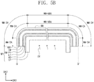
FIGS. 5A to 5G are cross-sectional views illustrating a process of manufacturing a display device according to an embodiment of the inventive concept.FIGS. 5A to 5C are cross-sectional views taken along line III-III' ofFIG. 4A , andFIGS. 5D to 5G are cross-sectional views taken along line II-II' ofFIG. 4A . In this embodiment, a process of manufacturing the display device DD inFIGS. 4B and 4C is exemplarily described. - As illustrated in
FIGS. 5A and5D , a window WM is provided. The window WM includes a first area WM-NBA and a second area WM-BA. The second area WM-BA may include a curved area WM-CA and a side area WM-SA corresponding to the curved area CA and the side area SA of the display device DD (refer toFIG. 1 ), respectively. The curved area WM-CA may have a curvature radius of about 2 mm to about 5 mm. The curvature radius may be measured at an outer surface or an inner surface of the window WM. - An angle between the first area WM-NBA and the side area WM-SA may be about 80° to about 90°. A width SS-W in the third directional axis DR3 of a side surface provided by the side area WM-SA may be about 4 mm to about 8 mm.
- A working panel WP is disposed on a pressing pad SPD. The working panel WP includes: a display module DM; a first adhesive member AM1 disposed on a top surface of the display module DM; a protection film LF disposed below the display module DM; a second adhesive member AM2 coupling the display module DM and the protection film LF; a carrier film CF disposed below the protection film LF; and a carrier adhesive member AD coupling the carrier film CF and the protection film LF. The pressing pad SPD may be a silicon pad.
- The working panel WP and the window WM are aligned with each other, and then the working panel WP is coupled to the window WM The first adhesive member AM1 is coupled to the first area WM-NBA and the second area WM-BA.
- Thereafter, the carrier adhesive member AD, the carrier film CF, and the pressing pad SPD are detached from the protection film LF.
- As illustrated in
FIGS. 5B and5E , a photo-curing process of the carrier adhesive member AD after the pressing pad SPD is removed may be selectively performed. An adhesion force of the carrier adhesive member AD may be weakened by irradiating the carrier adhesive member AD with ultraviolet rays. - As illustrated in
FIGS. 5C and5F , the carrier adhesive member AD having the weakened adhesive force may be detached from the protection film LF in conjunction with the carrier film CF. According to an embodiment of the inventive concept, the photo-curing process may not be performed. Although the photo-curing process is not performed, as an adhesive member having a relatively weak adhesion force is applied to the carrier adhesive member AD, the carrier adhesive member AD and the carrier film CF may be removed from the protection film LF without delamination of the first adhesive member AM1 and the second adhesive member AM2. - Next, as illustrated in
FIG. 5G , a process of bonding a driving control module DCM to the display module DM may be further performed. Also, a process of coupling a lower member to a lower side of the protection film LF may be further performed. However, the embodiment of the inventive concept is not particularly limited to the sequence of the bonding process and the lower member coupling process. - Referring to
FIGS. 5A to 5G , as the first area adhesive member AMP1 having a relatively small elastic modulus is disposed in the bending area WM-BA, a stress applied to the bending area WM-BA of the window WM by the display module DM and the protection film LF may be reduced. As each of the first adhesive member AM1 and the second adhesive member AM2 extends in the bending area WM-BA, the bending stress is reduced. - As the second area adhesive member AM-P2 having a relatively great elastic modulus is disposed between a bonding portion of the display module DM and the protection film LF, the bonding portion of the display module DM may have a relatively great strength in comparison with that of a bending portion of the display module DM. As the strength of the bonding portion of the display module DM is greater than a reference strength, a coupling force between the driving control module DCM and the display module DM may increase, and a defect generated in the bonding process may be reduced.
-
FIG. 6 is a perspective view illustrating a display device DD according to an embodiment of the inventive concept.FIG. 7 is an exploded perspective view illustrating the display device DD according to an embodiment of the inventive concept.FIG. 8 is a cross-sectional view taken along line IV-IV' ofFIG. 6 . Hereinafter, detailed descriptions on the same components described with reference toFIGS. 1 to 5F will be omitted. - As illustrated in
FIG. 6 , a display surface DD-IS includes a display area DD-DA and a non-display area DD-NDA1 and DD-NDA2. The non-display area DD-NDA includes a first non-display area DD-NDA1 and a second non-display area DD-NDA2. - The display surface DD-IS may include a non-bending area NBA and four bending areas BA. Also, the display surface DD-IS may include four corner bending areas CBA. Each of the corner bending areas CBA is disposed between two adjacent bending areas BA. At least a portion of the corner bending area CBA may be the non-display area DD-NDA. The four corner bending areas CBA may correspond to four second non-display areas DD-NDA2, respectively. Four first non-display areas DD-NDA1 may correspond to edge areas of the four bending area BA, respectively.
- As illustrated in
FIG. 7 , a window WM may include a first area WM-NBA (or planar area), four second areas WM-BA (or bending areas), and four third areas WM-CBA (or corner areas). The four second areas WM-BA and the four third areas WM-CBA correspond to the four bending areas BA and the four corner bending areas CBA of the display device DD inFIG. 1 , respectively. Two of the four bending areas WM-BA face each other in the first directional axis, and the other two face each other in the second directional axis DR2. - Referring to
FIGS. 6 to 8 , the display module DM overlaps all of the four bending areas WM-BA. The second portion DM-P2 of the display module DM may protrude to the outside from one of the four bending areas WM-BA. -
FIG. 9 is a plan view illustrating a display module DM according to an embodiment of the inventive concept.FIGS. 10A to 10C are cross-sectional views illustrating a process of manufacturing a display device according to an embodiment of the inventive concept. - As illustrated in
FIG. 9 , the display module DM includes a first portion DM-P1 coupled to the window WM and a second portion DM-P2 extending from the first portion DM-P1. The display module DM may include a non-bending area DM-NBA and four bending areas DM-BA corresponding to the non-bending area NBA and the four bending areas BA inFIG. 6 , respectively. - A method for manufacturing a display device according to the embodiment may be substantially the same as the method for manufacturing the display device described with reference to
FIGS. 5A to 5F . AlthoughFIGS. 10A to 10C are illustrated with respect to a cross-section taken along line II-II' ofFIG. 9 ,FIGS. 10A to 10C correspond toFIGS. 5D to 5F , respectively. Since the window WM inFIG. 2 and the window WM inFIG. 7 are different in shape, cross-sections of the manufacturing process are also different from each other. - On the cross-section, the bending area DM-BA of the display module DM is coupled to the second area WM-BA of the window WM through the first adhesive member AM1. As the first area adhesive member AM-P1 having a relatively small elastic modulus is disposed in the bending area WM-BA, the stress applied to the bending area WM-BA of the window WM by the display module DM and the protection film LF may be reduced. As each of the first adhesive member AM1 and the second adhesive member AM2 extends in the bending area WM-BA, the bending stress may be reduced.
- In an embodiment of the inventive concept, a photo-curing process in
FIG. 10B may be omitted. - As described above, the stress applied to the second area of the window by the bending of the display module and the protection film may be reduced. As the first area adhesive member having a relatively small elastic modulus is disposed between the display module and the protection film, the stress generated at the bending portion of the display module and the bending portion of the protection film, each of which has a small curvature radius, may be reduced. Thus, a crack defect of the window may be reduced.
- As the second area adhesive member having a relatively great elastic modulus is disposed between the bonding portion of the display module and the protection film, the bonding portion of the display module may have a relatively great strength in comparison with the bending portion of the display module. As the strength of the bending portion of the display module is greater than the reference strength, the coupling force between the circuit board and the display module may increase, and the defects generated in the bonding process may be reduced.
- Although the exemplary embodiments of the present invention have been described, it is understood that the present invention should not be limited to these exemplary embodiments but various changes and modifications can be made by one ordinary skilled in the art.
Claims (17)
- A display device (DD) comprising:a window (WM) comprising a first area (WM-NBA) configured to provide a front surface and a second area (WM-BA) bent from the first area to provide at last a side surface;a display module (DM) comprising a first portion (DM-P1) coupled to the window (WM) and a second portion (DM-P2) extending from the first portion (DM-P1);a protection film (LF) comprising a first film portion (LF-P1) corresponding to the first portion (DM-P1) and a second film portion (LF-P2) corresponding to the second portion (DM-P2), the protection film (LF) being disposed below the display module (DM);characterized bya first area adhesive member (AM-P1) configured to couple the first portion (DM-P1) and the first film portion (LF-P1);a second area adhesive member (AM-P2) configured to couple the second portion (DM-P2) and the second film portion (LF-P2) and having an elastic modulus greater than an elastic modulus of the first area adhesive member (AM-P1); anda circuit board (FPCB) coupled to the second portion (DM-P2).
- The display device (DD) of claim 1, wherein the first area adhesive member (AM-P1) has an elastic modulus of about 0.01 MPa to about 10 MPa, and
the second area adhesive member (AM-P2) has an elastic modulus of about 1 MPa to about 200 MPa. - The display device (DD) of at least one of claims 1 or 2, wherein the first area adhesive member (AM-P1) has a thickness greater than a thickness of the second area adhesive member (AM-P2).
- The display device (DD) of claim 3, wherein the first area adhesive member (AM-P1) has the thickness of about 1 µm to 100 µm, and
the second area adhesive member (AM-P2) has the thickness of about 1 µm to 200 µm. - The display device (DD) of at least one of claims 3 or 4, wherein the first film portion (LF-P1) has a thickness less than a thickness of the second film portion (LF-P2).
- The display device (DD) of at least one of claims 3 to 5, wherein on a plane, the first film portion (LF-P1) has an area greater than an area of the second film portion (LF-P2).
- The display device (DD) of at least one of claims 3 to 6, wherein on a plane, the first film portion (LF-P1) is spaced apart from the second film portion (LF-P2).
- The display device (DD) of at least one of claims 1 to 7, wherein the second area (WM-BA) further provides a curved surface, and
the second area (WM-BA) comprises a curved area (CA) configured to provide the curved surface and a side area (SA) configured to provide the side surface. - The display device (DD) of claim 8, wherein the curved area (CA) has a curvature radius of about 2 mm to about 5 mm.
- The display device (DD) of at least one of claims 8 or 9, wherein an angle between the first area (WM-NBA) and the side area (WM-SA) is about 80° to about 90°.
- The display device (DD) of claim 10, wherein the side surface has a width of about 4 mm to about 8 mm.
- The display device (DD) of at least one of claims 1 to 11, wherein the front surface is defined by a first directional axis (DR1) and a second directional axis (DR2),
the second area comprises two bending areas (BA) facing each other in the first directional axis (DR1) and overlapping the display module (DM) and two bending areas (BA) facing each other in the second directional axis (DR2) and overlapping the display module (DM). - The display device (DD) of claim 12, wherein the second portion (DM-P2) protrudes to the outside of one of the bending areas (BA).
- The display device (DD) of at least one of claims 1 to 13, wherein the display module (DM) comprises:a display panel (DP);an input sensor (IS) disposed on the display panel (DP); andan anti-reflection unit (RP) disposed on the display panel (DP).
- The display device (DD) of at least one of claims 1 to 14, wherein the second portion (DM-P2) is bent to face the first portion (DM-P1).
- The display device (DD) of at least one of claims 1 to 15, wherein the first area adhesive member (AM-P1) is coupled to the entire first portion (DM-P1), and the second area adhesive member (AM-P2) is coupled to the entire second portion (DM-P2).
- The display device (DD) of at least one of claims 1 to 16, wherein the second area adhesive member (AM-P2) is coupled to a portion of the first portion (DM-P1).
Applications Claiming Priority (1)
| Application Number | Priority Date | Filing Date | Title |
|---|---|---|---|
| KR1020190084498A KR102639429B1 (en) | 2019-07-12 | 2019-07-12 | Display device and manufacturing method of the same |
Publications (2)
| Publication Number | Publication Date |
|---|---|
| EP3764196A1 true EP3764196A1 (en) | 2021-01-13 |
| EP3764196B1 EP3764196B1 (en) | 2023-03-08 |
Family
ID=71515009
Family Applications (1)
| Application Number | Title | Priority Date | Filing Date |
|---|---|---|---|
| EP20184114.5A Active EP3764196B1 (en) | 2019-07-12 | 2020-07-06 | Display device |
Country Status (4)
| Country | Link |
|---|---|
| US (1) | US11927987B2 (en) |
| EP (1) | EP3764196B1 (en) |
| KR (1) | KR102639429B1 (en) |
| CN (1) | CN112216728A (en) |
Families Citing this family (5)
| Publication number | Priority date | Publication date | Assignee | Title |
|---|---|---|---|---|
| CN110634402A (en) * | 2019-08-28 | 2019-12-31 | 武汉华星光电半导体显示技术有限公司 | Display panel, bending method thereof and display device |
| CN212342186U (en) * | 2020-04-17 | 2021-01-12 | 京东方科技集团股份有限公司 | Curved surface folding display module and mobile terminal |
| JP2022035197A (en) * | 2020-08-20 | 2022-03-04 | 株式会社Joled | Display panel and display device |
| CN113689787B (en) * | 2021-08-02 | 2023-02-07 | 武汉华星光电半导体显示技术有限公司 | Display panel and display device |
| WO2023023888A1 (en) * | 2021-08-23 | 2023-03-02 | 京东方科技集团股份有限公司 | Touch substrate, display touch panel, and display device |
Citations (2)
| Publication number | Priority date | Publication date | Assignee | Title |
|---|---|---|---|---|
| US20190014669A1 (en) * | 2017-07-07 | 2019-01-10 | Samsung Display Co., Ltd. | Display device and method of fabricating the same |
| US20190057645A1 (en) * | 2017-08-18 | 2019-02-21 | Samsung Display Co., Ltd. | Display device and method of fabricating the same |
Family Cites Families (18)
| Publication number | Priority date | Publication date | Assignee | Title |
|---|---|---|---|---|
| JP5623754B2 (en) * | 2010-02-04 | 2014-11-12 | 株式会社ジャパンディスプレイ | Display device and manufacturing method thereof |
| KR101320385B1 (en) * | 2011-06-30 | 2013-10-23 | 삼성디스플레이 주식회사 | Flexible display panel and the display apparatus comprising the flexible display panel |
| KR101767565B1 (en) * | 2012-10-25 | 2017-08-14 | 삼성디스플레이 주식회사 | Apparatus for manufacturing flexible display device and manufacturing method for flexible display device using the same |
| KR20140052732A (en) * | 2012-10-25 | 2014-05-07 | 삼성디스플레이 주식회사 | Display device and method for manufacturing the same |
| KR101987763B1 (en) * | 2013-06-26 | 2019-06-11 | 엘지디스플레이 주식회사 | Method of fabricating flexible display device |
| KR102126712B1 (en) * | 2013-09-30 | 2020-06-26 | 삼성디스플레이 주식회사 | Display apparatus |
| US9430180B2 (en) | 2013-11-15 | 2016-08-30 | Semiconductor Energy Laboratory Co., Ltd | Display panel and electronic device |
| KR102281910B1 (en) * | 2014-06-26 | 2021-07-28 | 삼성디스플레이 주식회사 | Display module and display apparatus having the same |
| KR102250710B1 (en) | 2014-10-31 | 2021-05-10 | 엘지디스플레이 주식회사 | Organic light emitting display device and method of manufacturing the same |
| KR102296749B1 (en) * | 2015-04-03 | 2021-09-03 | 삼성디스플레이 주식회사 | Display device |
| KR102404370B1 (en) * | 2015-10-02 | 2022-06-03 | 삼성디스플레이 주식회사 | Window and display device having the same |
| KR101809991B1 (en) * | 2016-02-01 | 2017-12-18 | 안성룡 | The method for attaching a flexible panel to the curved window glass |
| KR102454824B1 (en) | 2016-03-25 | 2022-10-18 | 삼성디스플레이 주식회사 | Flexible display device |
| KR102451078B1 (en) | 2016-05-25 | 2022-10-06 | 삼성전자주식회사 | Electronic device having display with bended area and manufacturing method thereof |
| KR101871967B1 (en) | 2016-08-30 | 2018-06-28 | 주식회사 나래나노텍 | An Improved Apparatus of Bonding Curved Cover Element |
| KR101955765B1 (en) * | 2016-08-31 | 2019-03-07 | 삼성에스디아이 주식회사 | Polarizing plate and optical display apparatus comprising the same |
| CN106910823B (en) * | 2017-04-05 | 2019-08-06 | 上海天马微电子有限公司 | A kind of flexible display panels and flexible display apparatus |
| KR102404974B1 (en) | 2017-09-12 | 2022-06-03 | 삼성디스플레이 주식회사 | Display device |
-
2019
- 2019-07-12 KR KR1020190084498A patent/KR102639429B1/en active IP Right Grant
-
2020
- 2020-06-17 US US16/903,844 patent/US11927987B2/en active Active
- 2020-07-06 EP EP20184114.5A patent/EP3764196B1/en active Active
- 2020-07-08 CN CN202010650332.XA patent/CN112216728A/en active Pending
Patent Citations (2)
| Publication number | Priority date | Publication date | Assignee | Title |
|---|---|---|---|---|
| US20190014669A1 (en) * | 2017-07-07 | 2019-01-10 | Samsung Display Co., Ltd. | Display device and method of fabricating the same |
| US20190057645A1 (en) * | 2017-08-18 | 2019-02-21 | Samsung Display Co., Ltd. | Display device and method of fabricating the same |
Also Published As
| Publication number | Publication date |
|---|---|
| US20210013447A1 (en) | 2021-01-14 |
| US11927987B2 (en) | 2024-03-12 |
| KR102639429B1 (en) | 2024-02-23 |
| CN112216728A (en) | 2021-01-12 |
| KR20210008262A (en) | 2021-01-21 |
| EP3764196B1 (en) | 2023-03-08 |
Similar Documents
| Publication | Publication Date | Title |
|---|---|---|
| EP3764196B1 (en) | Display device | |
| KR102643282B1 (en) | Display device | |
| EP3664148B1 (en) | Display device and electronic device having the same | |
| US9947882B2 (en) | Electronic devices with robust flexible displays | |
| EP3454375B1 (en) | Organic light emitting display and method for manufacturing the same | |
| US10181576B2 (en) | Display device | |
| KR20200082363A (en) | Flexible display apparatus and electronic device comprising the same | |
| KR102333206B1 (en) | Electronic apparatus | |
| KR20150012389A (en) | flexible touch screen panel and flexible display device with the same | |
| CN111047985B (en) | Display device | |
| US11626567B2 (en) | Display device | |
| CN111338497A (en) | Electronic device | |
| CN114648917A (en) | Electronic device | |
| KR20200049321A (en) | Display apparatus and multi screen display apparatus comprising the same | |
| CN114078381A (en) | Display device and electronic device including the same | |
| KR20220023836A (en) | Display device and electronic device having the same | |
| US11910581B2 (en) | Display device | |
| KR20200057868A (en) | Electronic device | |
| US20200313114A1 (en) | Window for display device, method for manufacturing the same, and display device including the same | |
| US20230403907A1 (en) | Display device and method for manufacturing the same | |
| US20240147642A1 (en) | Display device including fingerprint detection sensor | |
| US20220374047A1 (en) | Display device | |
| KR20220042023A (en) | Pad for priniting, manufacturing method of window using the same, and manufacturing method of electronic device using the same | |
| CN117789597A (en) | Display module and method for attaching a display module and a window member | |
| CN115148092A (en) | Display device, method of manufacturing window, and method of manufacturing display device |
Legal Events
| Date | Code | Title | Description |
|---|---|---|---|
| PUAI | Public reference made under article 153(3) epc to a published international application that has entered the european phase |
Free format text: ORIGINAL CODE: 0009012 |
|
| STAA | Information on the status of an ep patent application or granted ep patent |
Free format text: STATUS: THE APPLICATION HAS BEEN PUBLISHED |
|
| AK | Designated contracting states |
Kind code of ref document: A1 Designated state(s): AL AT BE BG CH CY CZ DE DK EE ES FI FR GB GR HR HU IE IS IT LI LT LU LV MC MK MT NL NO PL PT RO RS SE SI SK SM TR |
|
| AX | Request for extension of the european patent |
Extension state: BA ME |
|
| STAA | Information on the status of an ep patent application or granted ep patent |
Free format text: STATUS: REQUEST FOR EXAMINATION WAS MADE |
|
| 17P | Request for examination filed |
Effective date: 20210712 |
|
| RBV | Designated contracting states (corrected) |
Designated state(s): AL AT BE BG CH CY CZ DE DK EE ES FI FR GB GR HR HU IE IS IT LI LT LU LV MC MK MT NL NO PL PT RO RS SE SI SK SM TR |
|
| GRAP | Despatch of communication of intention to grant a patent |
Free format text: ORIGINAL CODE: EPIDOSNIGR1 |
|
| STAA | Information on the status of an ep patent application or granted ep patent |
Free format text: STATUS: GRANT OF PATENT IS INTENDED |
|
| RIC1 | Information provided on ipc code assigned before grant |
Ipc: H04M 1/18 20060101ALN20220831BHEP Ipc: H04M 1/02 20060101ALI20220831BHEP Ipc: G06F 1/16 20060101AFI20220831BHEP |
|
| INTG | Intention to grant announced |
Effective date: 20220926 |
|
| GRAS | Grant fee paid |
Free format text: ORIGINAL CODE: EPIDOSNIGR3 |
|
| GRAA | (expected) grant |
Free format text: ORIGINAL CODE: 0009210 |
|
| STAA | Information on the status of an ep patent application or granted ep patent |
Free format text: STATUS: THE PATENT HAS BEEN GRANTED |
|
| AK | Designated contracting states |
Kind code of ref document: B1 Designated state(s): AL AT BE BG CH CY CZ DE DK EE ES FI FR GB GR HR HU IE IS IT LI LT LU LV MC MK MT NL NO PL PT RO RS SE SI SK SM TR |
|
| REG | Reference to a national code |
Ref country code: CH Ref legal event code: EP Ref country code: AT Ref legal event code: REF Ref document number: 1553020 Country of ref document: AT Kind code of ref document: T Effective date: 20230315 |
|
| REG | Reference to a national code |
Ref country code: NL Ref legal event code: FP |
|
| REG | Reference to a national code |
Ref country code: DE Ref legal event code: R096 Ref document number: 602020008653 Country of ref document: DE |
|
| REG | Reference to a national code |
Ref country code: IE Ref legal event code: FG4D |
|
| P01 | Opt-out of the competence of the unified patent court (upc) registered |
Effective date: 20230516 |
|
| REG | Reference to a national code |
Ref country code: LT Ref legal event code: MG9D |
|
| PG25 | Lapsed in a contracting state [announced via postgrant information from national office to epo] |
Ref country code: RS Free format text: LAPSE BECAUSE OF FAILURE TO SUBMIT A TRANSLATION OF THE DESCRIPTION OR TO PAY THE FEE WITHIN THE PRESCRIBED TIME-LIMIT Effective date: 20230308 Ref country code: NO Free format text: LAPSE BECAUSE OF FAILURE TO SUBMIT A TRANSLATION OF THE DESCRIPTION OR TO PAY THE FEE WITHIN THE PRESCRIBED TIME-LIMIT Effective date: 20230608 Ref country code: LV Free format text: LAPSE BECAUSE OF FAILURE TO SUBMIT A TRANSLATION OF THE DESCRIPTION OR TO PAY THE FEE WITHIN THE PRESCRIBED TIME-LIMIT Effective date: 20230308 Ref country code: LT Free format text: LAPSE BECAUSE OF FAILURE TO SUBMIT A TRANSLATION OF THE DESCRIPTION OR TO PAY THE FEE WITHIN THE PRESCRIBED TIME-LIMIT Effective date: 20230308 Ref country code: HR Free format text: LAPSE BECAUSE OF FAILURE TO SUBMIT A TRANSLATION OF THE DESCRIPTION OR TO PAY THE FEE WITHIN THE PRESCRIBED TIME-LIMIT Effective date: 20230308 Ref country code: ES Free format text: LAPSE BECAUSE OF FAILURE TO SUBMIT A TRANSLATION OF THE DESCRIPTION OR TO PAY THE FEE WITHIN THE PRESCRIBED TIME-LIMIT Effective date: 20230308 |
|
| PGFP | Annual fee paid to national office [announced via postgrant information from national office to epo] |
Ref country code: NL Payment date: 20230621 Year of fee payment: 4 Ref country code: FR Payment date: 20230621 Year of fee payment: 4 |
|
| REG | Reference to a national code |
Ref country code: AT Ref legal event code: MK05 Ref document number: 1553020 Country of ref document: AT Kind code of ref document: T Effective date: 20230308 |
|
| PG25 | Lapsed in a contracting state [announced via postgrant information from national office to epo] |
Ref country code: SE Free format text: LAPSE BECAUSE OF FAILURE TO SUBMIT A TRANSLATION OF THE DESCRIPTION OR TO PAY THE FEE WITHIN THE PRESCRIBED TIME-LIMIT Effective date: 20230308 Ref country code: GR Free format text: LAPSE BECAUSE OF FAILURE TO SUBMIT A TRANSLATION OF THE DESCRIPTION OR TO PAY THE FEE WITHIN THE PRESCRIBED TIME-LIMIT Effective date: 20230609 Ref country code: FI Free format text: LAPSE BECAUSE OF FAILURE TO SUBMIT A TRANSLATION OF THE DESCRIPTION OR TO PAY THE FEE WITHIN THE PRESCRIBED TIME-LIMIT Effective date: 20230308 |
|
| PG25 | Lapsed in a contracting state [announced via postgrant information from national office to epo] |
Ref country code: SM Free format text: LAPSE BECAUSE OF FAILURE TO SUBMIT A TRANSLATION OF THE DESCRIPTION OR TO PAY THE FEE WITHIN THE PRESCRIBED TIME-LIMIT Effective date: 20230308 Ref country code: RO Free format text: LAPSE BECAUSE OF FAILURE TO SUBMIT A TRANSLATION OF THE DESCRIPTION OR TO PAY THE FEE WITHIN THE PRESCRIBED TIME-LIMIT Effective date: 20230308 Ref country code: PT Free format text: LAPSE BECAUSE OF FAILURE TO SUBMIT A TRANSLATION OF THE DESCRIPTION OR TO PAY THE FEE WITHIN THE PRESCRIBED TIME-LIMIT Effective date: 20230710 Ref country code: EE Free format text: LAPSE BECAUSE OF FAILURE TO SUBMIT A TRANSLATION OF THE DESCRIPTION OR TO PAY THE FEE WITHIN THE PRESCRIBED TIME-LIMIT Effective date: 20230308 Ref country code: CZ Free format text: LAPSE BECAUSE OF FAILURE TO SUBMIT A TRANSLATION OF THE DESCRIPTION OR TO PAY THE FEE WITHIN THE PRESCRIBED TIME-LIMIT Effective date: 20230308 Ref country code: AT Free format text: LAPSE BECAUSE OF FAILURE TO SUBMIT A TRANSLATION OF THE DESCRIPTION OR TO PAY THE FEE WITHIN THE PRESCRIBED TIME-LIMIT Effective date: 20230308 |
|
| PG25 | Lapsed in a contracting state [announced via postgrant information from national office to epo] |
Ref country code: SK Free format text: LAPSE BECAUSE OF FAILURE TO SUBMIT A TRANSLATION OF THE DESCRIPTION OR TO PAY THE FEE WITHIN THE PRESCRIBED TIME-LIMIT Effective date: 20230308 Ref country code: PL Free format text: LAPSE BECAUSE OF FAILURE TO SUBMIT A TRANSLATION OF THE DESCRIPTION OR TO PAY THE FEE WITHIN THE PRESCRIBED TIME-LIMIT Effective date: 20230308 Ref country code: IS Free format text: LAPSE BECAUSE OF FAILURE TO SUBMIT A TRANSLATION OF THE DESCRIPTION OR TO PAY THE FEE WITHIN THE PRESCRIBED TIME-LIMIT Effective date: 20230708 |
|
| PGFP | Annual fee paid to national office [announced via postgrant information from national office to epo] |
Ref country code: DE Payment date: 20230620 Year of fee payment: 4 |
|
| REG | Reference to a national code |
Ref country code: DE Ref legal event code: R097 Ref document number: 602020008653 Country of ref document: DE |
|
| PLBE | No opposition filed within time limit |
Free format text: ORIGINAL CODE: 0009261 |
|
| STAA | Information on the status of an ep patent application or granted ep patent |
Free format text: STATUS: NO OPPOSITION FILED WITHIN TIME LIMIT |
|
| PG25 | Lapsed in a contracting state [announced via postgrant information from national office to epo] |
Ref country code: SI Free format text: LAPSE BECAUSE OF FAILURE TO SUBMIT A TRANSLATION OF THE DESCRIPTION OR TO PAY THE FEE WITHIN THE PRESCRIBED TIME-LIMIT Effective date: 20230308 Ref country code: DK Free format text: LAPSE BECAUSE OF FAILURE TO SUBMIT A TRANSLATION OF THE DESCRIPTION OR TO PAY THE FEE WITHIN THE PRESCRIBED TIME-LIMIT Effective date: 20230308 |
|
| 26N | No opposition filed |
Effective date: 20231211 |
|
| PG25 | Lapsed in a contracting state [announced via postgrant information from national office to epo] |
Ref country code: MC Free format text: LAPSE BECAUSE OF FAILURE TO SUBMIT A TRANSLATION OF THE DESCRIPTION OR TO PAY THE FEE WITHIN THE PRESCRIBED TIME-LIMIT Effective date: 20230308 |
|
| PG25 | Lapsed in a contracting state [announced via postgrant information from national office to epo] |
Ref country code: MC Free format text: LAPSE BECAUSE OF FAILURE TO SUBMIT A TRANSLATION OF THE DESCRIPTION OR TO PAY THE FEE WITHIN THE PRESCRIBED TIME-LIMIT Effective date: 20230308 |
|
| REG | Reference to a national code |
Ref country code: CH Ref legal event code: PL |
|
| REG | Reference to a national code |
Ref country code: BE Ref legal event code: MM Effective date: 20230731 |
|
| PG25 | Lapsed in a contracting state [announced via postgrant information from national office to epo] |
Ref country code: LU Free format text: LAPSE BECAUSE OF NON-PAYMENT OF DUE FEES Effective date: 20230706 |
|
| PG25 | Lapsed in a contracting state [announced via postgrant information from national office to epo] |
Ref country code: LU Free format text: LAPSE BECAUSE OF NON-PAYMENT OF DUE FEES Effective date: 20230706 |