EP3763976B1 - Bauteil mit einem elektronischen informationsträger - Google Patents
Bauteil mit einem elektronischen informationsträger Download PDFInfo
- Publication number
- EP3763976B1 EP3763976B1 EP20184975.9A EP20184975A EP3763976B1 EP 3763976 B1 EP3763976 B1 EP 3763976B1 EP 20184975 A EP20184975 A EP 20184975A EP 3763976 B1 EP3763976 B1 EP 3763976B1
- Authority
- EP
- European Patent Office
- Prior art keywords
- component
- pin
- information carrier
- diaphragm
- carrier
- Prior art date
- Legal status (The legal status is an assumption and is not a legal conclusion. Google has not performed a legal analysis and makes no representation as to the accuracy of the status listed.)
- Active
Links
Images

Classifications
-
- F—MECHANICAL ENGINEERING; LIGHTING; HEATING; WEAPONS; BLASTING
- F16—ENGINEERING ELEMENTS AND UNITS; GENERAL MEASURES FOR PRODUCING AND MAINTAINING EFFECTIVE FUNCTIONING OF MACHINES OR INSTALLATIONS; THERMAL INSULATION IN GENERAL
- F16K—VALVES; TAPS; COCKS; ACTUATING-FLOATS; DEVICES FOR VENTING OR AERATING
- F16K7/00—Diaphragm valves or cut-off apparatus, e.g. with a member deformed, but not moved bodily, to close the passage ; Pinch valves
- F16K7/12—Diaphragm valves or cut-off apparatus, e.g. with a member deformed, but not moved bodily, to close the passage ; Pinch valves with flat, dished, or bowl-shaped diaphragm
-
- F—MECHANICAL ENGINEERING; LIGHTING; HEATING; WEAPONS; BLASTING
- F16—ENGINEERING ELEMENTS AND UNITS; GENERAL MEASURES FOR PRODUCING AND MAINTAINING EFFECTIVE FUNCTIONING OF MACHINES OR INSTALLATIONS; THERMAL INSULATION IN GENERAL
- F16K—VALVES; TAPS; COCKS; ACTUATING-FLOATS; DEVICES FOR VENTING OR AERATING
- F16K37/00—Special means in or on valves or other cut-off apparatus for indicating or recording operation thereof, or for enabling an alarm to be given
- F16K37/0025—Electrical or magnetic means
- F16K37/0041—Electrical or magnetic means for measuring valve parameters
Definitions
- the invention relates to a component in the form of a membrane for a diaphragm valve and/or a diaphragm pump, with an electronic information carrier.
- RFID chips are used in particular as electronic information carriers.
- such electronic information carriers are usually introduced into the corresponding component during production, for example, introduced into an injection mold for producing the component and overmolded there, or, in the case of a multilayer component, arranged between the layers of the component.
- the publication EN 10 2016 106 818 B3 A multilayer membrane is known, wherein a recess is provided in a middle layer into which the information carrier is introduced and covered with the cover layers.
- a membrane according to the preamble of claim 1 is known from the document EN 20 2018 105 892 U1 known.
- the object of the present invention is therefore to provide an improved component in the form of a membrane for a diaphragm valve and/or a diaphragm pump with an electronic information carrier.
- the present invention comprises a component in the form of a membrane for a membrane valve and/or a membrane pump with an electronic information carrier. It is provided that the component has a recess and a pin, wherein the information carrier is connected to the component via the recess and the pin. This ensures simple manufacture and improved recycling.
- the component thus has both a recess and a pin, wherein the electronic information carrier is connected to the component via the recess and the pin.
- the pin is fastened in the recess.
- the recess serves to fasten the pin, and the pin in turn serves to fasten a carrier element for the information carrier to the component.
- the recess is a blind hole.
- a hole can be made particularly easily in a component and then serves to connect to the information carrier by means of a pin inserted into the blind hole.
- the pin can be a stud bolt.
- the pin protrudes from the surface of the component. This allows the electronic information carrier to be attached to the part of the pin protruding from the surface of the component.
- the component comprises a carrier element which is connected to the pin and on and/or in which the information carrier is arranged.
- the carrier element can in particular be a cap.
- the cap thus serves as a carrier for the electronic information carrier and is connected to the pin, whereby the pin is fastened in a recess in the component.
- the carrier element is made of plastic and/or an elastomer.
- the carrier element can be made of a thermoplastic material.
- the carrier element rests on a surface of the component in a peripheral region of the pin.
- the carrier element can have a mushroom shape together with the pin.
- the information carrier is connected to the component by means of the recess, the pin and the carrier element.
- the information carrier is arranged inside the carrier element.
- the information carrier can be enclosed by the material of the carrier element.
- the carrier element is manufactured using the injection molding process, whereby the information carrier is inserted into the injection mold and overmolded with the material of the carrier element.
- the information carrier is arranged on an underside of the carrier element facing the surface of the component.
- the information carrier can be glued to such an underside of the carrier element.
- the information carrier surrounds the recess and/or the pin in a ring shape. This makes it possible to achieve a relatively large base area for the information carrier.
- the information carrier is connected to a sensor arranged in the pin.
- the pin can have a bore into which a sensor is inserted, the information carrier being connected to this sensor.
- the information carrier can be connected to a sensor through the pin.
- the pin can have a hole through which an electronic connection line runs, which connects a sensor arranged within the component to the electronic information carrier.
- the information carrier preferably comprises an evaluation and/or transmission unit in order to evaluate and/or transmit signals from the sensor.
- a detachable connection is provided between the information carrier and the component. This enables easy separation between the information carrier and the component for recycling purposes.
- the pin is detachably connected to the recess.
- the pin can be held in the recess by force and/or by a clip connection.
- the pin can be manufactured in one piece with the carrier element and/or be connected to the carrier element in a material-locking manner - regardless of the connection between the pin and the component.
- the carrier element can be glued to the pin.
- the carrier element is detachably connected to the pin, for example by force-fitting and/or held thereto by a clip connection.
- the pin can be manufactured in one piece with the component or integrally connected to the component - regardless of the connection between the pin and the support element.
- the pin can be glued into the recess.
- the information carrier can be read wirelessly.
- the information carrier is an RFID chip.
- the RFID chip comprises a memory element in which data is stored, whereby this data can be read wirelessly via the RFID chip.
- this data can be product data of the component.
- the RFID chip can be used to read and/or wirelessly transmit sensor data.
- the RFID chip can be an active or a passive RFID chip.
- the electronic information carrier is not arranged inside the component, but positioned outside the component. This results in better optical detection of the position of the information carrier and a better radio connection, since it is surrounded by less metal.
- the carrier element in particular the cap, in or on which the electronic information carrier is arranged, can furthermore have a different colour from the rest of the component.
- the component according to the invention is a planar element.
- the electronic information carrier is also a planar element, wherein the extension plane of the electronic information carrier preferably runs parallel to the extension plane of the planar component.
- the component is a membrane for a membrane valve and/or a membrane pump.
- it can be a multi-layer membrane and/or a membrane with at least one layer made of an elastomer.
- the membrane can also comprise one or more metal layers.
- the membrane has a functional area and a tab, wherein the recess and/or the pin on the Tab is arranged.
- the functional area can be arranged in an area around which the media flows and/or can be deformed during operation.
- the tab on the other hand, preferably protrudes from the area around which the media flows and/or a housing. Alternatively or additionally, the tab can remain undeformed during operation.
- the present invention further comprises a diaphragm valve and/or a diaphragm pump with a component according to the invention in the form of a diaphragm, as described above.
- the membrane is clamped between two housing elements of the diaphragm valve and/or the diaphragm pump.
- the recess and/or the pin is provided in a region of the diaphragm which protrudes from a housing of the diaphragm valve and/or the diaphragm pump.
- an electronic information carrier can be connected to the component on which this information is stored.
- this information can be component parameters and/or sensor data.
- the reading of such an electronic information carrier can be used for condition monitoring.
- the electronic information carrier is in particular a wirelessly readable information carrier, in particular an RFID chip.
- the component is a membrane for a membrane pump and/or a membrane valve.
- the membrane can have a multi-layer structure.
- One or more layers can consist of an elastomer and/or a metal.
- the present invention offers the possibility of separating the electronic information carrier and in particular the RFID chip from the component more easily, thus enabling improved recycling. Furthermore, the readability of the electronic information carrier is improved and manufacturing is simplified.
- the electronic information carrier is not arranged inside the component, and in particular not inside the membrane, but is arranged outside the actual component and connected to the component by means of a pin.
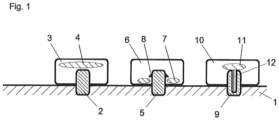
- Fig.1 shows three possibilities how an electronic information carrier 4, 7, 11 can be connected to the component 1 via a pin 2, 5, 9.
- the pin 2, 5, 9 protrudes from a surface of the component.
- a carrier element in the form of a cap 3, 6, 10 is attached to the pin 2, 5, 9, in or on which the information carrier is arranged.
- the cap 3, 6, 10 can in particular be made from an elastomer.
- the electronic information carrier can be arranged inside the cap.
- it can be overmolded with the cap material during the production of the cap.
- the information carrier 7 is arranged on an underside of the cap 6 facing the component 1, for example glued to it.
- the information carrier 7 could also be arranged inside the cap here.
- the electronic information carrier is designed as a flat element which is arranged above the pin 2 in the cap 3.
- the electronic information carrier is ring-shaped and surrounds the pin 5.
- the pin 9 has a bore in which a sensor 12 is arranged.
- the electronic information carrier 11 has connections with which it is connected to the sensor 12.
- a connecting line could pass through the pin 9 in order to connect the electronic information carrier to a sensor arranged within the component 1.
- the electronic information carrier is preferably designed such that it evaluates sensor signals and/or transmits them wirelessly so that the sensor can be read out by means of the electronic information carrier.
- the cap 3, 6, 10 rests with its underside on a surface of the component 1 in a peripheral region of the pin 2, 5, 9. Furthermore, the cap can be glued to the surface in this peripheral region.
- the pin serves as the connection between the component and the cap, which carries the electronic information carrier.
- the cap can be, as shown on the left in Fig.1 shown, pressed onto the pin. Alternatively or additionally, the cap can be glued to the pin and/or the surface of the component.
- the pin 8 has locking lugs which form a clip connection with corresponding recesses in the cap 6.
- the pin 2, 5, 9 is manufactured in one piece with the component.
- it can be a raised pin which is machined.
- the pin is held in a recess in the component.
- this recess can be a blind hole which is made in a surface of the component.
- the recess or the blind hole are preferably perpendicular to a plane of the component, in particular perpendicular to the membrane plane and/or the surface of the component.
- the pin can, for example, be hammered into the recess or blind hole. Alternatively or additionally, the pin can be glued into the recess or blind hole.
- an FDA-compliant adhesive is preferably used.
- an adhesive or a corresponding potting compound accepted in the pharmaceutical industry can be used.
- the component is the membrane of a membrane valve and/or a membrane pump.
- this can be arranged with its functional area in an area around which media flows.
- any other applications are also conceivable.
- the electronic information carrier according to the invention can be arranged inside a drive and/or housing.
- a drive and/or housing can be arranged inside a drive and/or housing.
- the component can therefore have a functional area and a tab, the functional area being arranged within a housing and preferably in contact with the media, while the tab protrudes from the housing.
- the electronic information carrier is preferably arranged on the tab.
- the recess and/or the pin can be arranged on the tab of the component.
- the present invention therefore offers significant advantages both in terms of production and in terms of environmental protection.
- the electronics can be separated from the components relatively easily during recycling. If necessary, the electronics can also be reused.
- connection between the electronic information carrier and the component represents a one-time connection.
- the connection can be designed in such a way that after a separation of the electronic information carrier There is no possibility of reconnecting the components in the same way without this being noticeable optically and/or electronically.
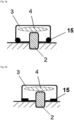
- the Fig. 2a and 2b show examples of the designs of the Fig.1 , wherein a seal 15 seals the cap (3, 6, 10) against the surface of the component 1.
- the seal can be designed as an O-ring or flat seal.
- the seal 15 and/or the pin 2, 5, 9 are destroyed in their function as soon as the cap 3, 6, 10 is removed.
- the information carrier 4, 7, 11 can also be destroyed. This guarantees a one-time connection in this configuration. A new use therefore requires a new or at least a newly activated information carrier in a new cap, which must at least be equipped with a new seal. This restores full functionality.
Landscapes
- Engineering & Computer Science (AREA)
- General Engineering & Computer Science (AREA)
- Mechanical Engineering (AREA)
- Measuring Fluid Pressure (AREA)
- Reciprocating Pumps (AREA)
Description
- Die Erfindung betrifft ein Bauteil in Form einer Membran für ein Membranventil und/oder eine Membranpumpe, mit einem elektronischen Informationsträger.
- Zur Zuordnung von Informationen zu einem Bauteil und/oder zum Auslesen von Sensordaten aus einem Bauteil werden zunehmend elektronische Informationsträger eingesetzt, welche mit dem Bauteil verbunden werden. Insbesondere werden als elektronische Informationsträger RFID-Chips eingesetzt.
- Im Stand der Technik werden solche elektronischen Informationsträger üblicherweise im Rahmen der Herstellung in das entsprechende Bauteil eingebracht, beispielsweise in eine Spritzgussform zur Herstellung des Bauteils eingebracht und dort umspritzt, oder bei einem mehrlagigen Bauteil zwischen den Lagen des Bauteils angeordnet.
- Beispielsweise ist aus der Druckschrift
DE 10 2016 106 818 B3 eine mehrlagige Membran bekannt, wobei in einer mittleren Lage eine Aussparung vorgesehen ist, in welche der Informationsträger eingebracht wird, und mit den Deckschichten bedeckt wird. - Die Herstellung solcher Bauteile ist aufwendig. Weiterhin weisen solche Bauteile im Hinblick auf das Recycling schlechte Eigenschaften auf.
- Eine Membran gemäß dem Oberbegriff von Anspruch 1 ist aus der Druckschrift
DE 20 2018 105 892 U1 bekannt. - Weitere Bauteile mit daran angeordneten Informationsträgern sind aus den Druckschriften
DE 10 2017 128 229 A1 ,DE 20 2018 105 500 U1 undUS 7 256 699 B2 bekannt. - Aufgabe der vorliegenden Erfindung ist es daher, ein verbessertes Bauteil in Form einer Membran für ein Membranventil und/oder eine Membranpumpe mit einem elektronischen Informationsträger zur Verfügung zu stellen.
- Diese Aufgabe wird durch ein Bauteil in Form einer Membran für ein Membranventil und/oder eine Membranpumpe gemäß Anspruch 1 gelöst. Bevorzugte Ausgestaltungen der vorliegenden Erfindung sind Gegenstand der Unteransprüche.
- Die vorliegende Erfindung umfasst ein Bauteil in Form einer Membran für ein Membranventil und/oder eine Membranpumpe mit einem elektronischen Informationsträger. Dabei ist vorgesehen, dass das Bauteil eine Aussparung und einen Stift aufweist, wobei der Informationsträger über die Aussparung und den Stift mit dem Bauteil verbunden ist. Hierdurch wird eine einfache Herstellbarkeit und ein verbessertes Recycling gewährleistet.
- Erfindungsgemäß weist das Bauteil damit sowohl eine Aussparung als auch einen Stift auf, wobei der elektronische Informationsträger über Aussparung und Stift mit dem Bauteil verbunden ist.
- Gemäß der vorliegenden Erfindung ist der Stift in der Aussparung befestigt. Dabei dient die Aussparung der Befestigung des Stiftes, und der Stift wiederum der Befestigung eines Trägerelementes für den Informationsträger mit dem Bauteil.
- Gemäß der Erfindung handelt es sich bei der Aussparung um ein Sackloch. Ein solches kann besonders einfach in ein Bauteil eingebracht werden, und dient dann der Verbindung mit dem Informationsträger mittels eines in das Sackloch eingebrachten Stiftes.
- In einer möglichen Ausgestaltung kann es sich bei dem Stift um einen Stehbolzen handeln.
- Gemäß der Erfindung ragt der Stift aus der Oberfläche des Bauteils heraus. Hierdurch kann der elektronische Informationsträger an dem aus der Oberfläche des Bauteils herausragenden Teil des Stiftes befestigt werden.
- Gemäß der vorliegenden Erfindung umfasst das Bauteil ein Trägerelement, welches mit dem Stift verbunden ist und an und/oder in welchem der Informationsträger angeordnet ist.
- Bei dem Trägerelement kann es sich insbesondere um eine Kappe handeln. Die Kappe dient damit als Träger für den elektronischen Informationsträger und ist mit dem Stift verbunden, wobei der Stift in einer Aussparung des Bauteils befestigt ist.
- In einer möglichen Ausgestaltung der vorliegenden Erfindung ist das Trägerelement aus Kunststoff und/oder einem Elastomer gefertigt. Alternativ oder zusätzlich kann das Trägerelement aus einem thermoplastischen Kunststoff gefertigt sein.
- In einer möglichen Ausgestaltung der vorliegenden Erfindung liegt das Trägerelement in einem Umfangsbereich des Stiftes auf einer Oberfläche des Bauteiles auf. Insbesondere kann das Trägerelement dabei zusammen mit dem Stift eine Pilz-Form aufweisen.
- Erfindungsgemäß besteht eine Reihe von Möglichkeiten, wie der Informationsträger mittels der Aussparung, des Stiftes und des Trägerelementes mit dem Bauteil verbunden ist.
- In einer ersten Ausgestaltung ist der Informationsträger im Inneren des Trägerelementes angeordnet. Insbesondere kann der Informationsträger vom Material des Trägerelementes umschlossen sein. In einer möglichen Ausgestaltung der vorliegenden Erfindung wird das Trägerelement im Spritzgussverfahren hergestellt, wobei der Informationsträger in die Spritzgussform eingebracht und mit dem Material des Trägerelementes umspritzt wird.
- In einer weiteren Ausgestaltung der vorliegenden Erfindung ist der Informationsträger an einer der Oberfläche des Bauteils zugewandten Unterseite des Trägerelementes angeordnet. Beispielsweise kann der Informationsträger mit einer solchen Unterseite des Trägerelementes verklebt werden.
- Weitere mögliche Ausgestaltungen des erfindungsgemäßen Bauteils, welche mit allen der oben genannten Optionen anwendbar sind, werden im Folgenden beschrieben:
In einer möglichen Ausgestaltung der vorliegenden Erfindung umgibt der Informationsträger die Aussparung und/oder den Stift ringförmig. Hierdurch kann eine relativ große Grundfläche des Informationsträgers erreicht werden. - In einer möglichen Ausgestaltung der vorliegenden Erfindung steht der Informationsträger mit einem in dem Stift angeordneten Sensor in Verbindung. Insbesondere kann der Stift dabei eine Bohrung aufweisen, in welche ein Sensor eingebracht ist, wobei der Informationsträger mit diesem Sensor in Verbindung steht.
- Alternativ oder zusätzlich kann der Informationsträger durch den Stift hindurch mit einem Sensor in Verbindung stehen. Insbesondere kann der Stift dabei eine Bohrung aufweisen, durch welche hindurch eine elektronische Verbindungsleitung führt, welche einen innerhalb des Bauteils angeordneten Sensor mit dem elektronischen Informationsträger verbindet.
- Steht der Informationsträger mit einem Sensor in Verbindung, umfasst der Informationsträger bevorzugt eine Auswerte- und/oder Übertragungseinheit, um Signale des Sensors auszuwerten und/oder zu übertragen.
- In einer möglichen Ausgestaltung der vorliegenden Erfindung ist eine lösbare Verbindung zwischen dem Informationsträger und dem Bauteil vorgesehen. Dies ermöglicht eine einfache Trennung zwischen Informationsträger und Bauteil für Zwecke des Recyclings.
- In einer ersten Variante der vorliegenden Erfindung ist der Stift lösbar mit der Aussparung verbunden. Beispielsweise kann der Stift kraftschlüssig und/oder durch eine Clip-Verbindung in der Aussparung gehalten sein.
- Der Stift kann - auch unabhängig von der Verbindung zwischen Stift und Bauteil - einstückig mit dem Trägerelement gefertigt und/oder stoffschlüssig mit dem Trägerelement in Verbindung stehen. Beispielsweise kann das Trägerelement dabei mit dem Stift verklebt sein.
- In einer zweiten Variante der vorliegenden Erfindung ist das Trägerelement lösbar mit dem Stift verbunden, beispielsweise kraftschlüssig und/oder durch eine Clip-Verbindung an diesem gehalten.
- Der Stift kann - auch unabhängig von der Verbindung zwischen Stift und Trägerelement - einstückig mit dem Bauteil gefertigt oder stoffschlüssig mit dem Bauteil verbunden sein. Beispielsweise kann der Stift in der Aussparung verklebt sein.
- In einer möglichen Ausgestaltung der vorliegenden Erfindung ist der Informationsträger drahtlos auslesbar. Insbesondere handelt es sich bei dem Informationsträger um einen RFID-Chip.
- In einer möglichen Ausgestaltung der vorliegenden Erfindung umfasst der RFID-Chip ein Speicherelement, in welchem Daten abgespeichert sind, wobei diese Daten drahtlos über den RFID-Chip ausgelesen werden können. Beispielsweise kann es sich bei diesen Daten um Produktdaten des Bauteils handeln.
- Alternativ oder zusätzlich kann der RFID-Chip zum Auslesen und/oder zum drahtlosen Übertragen von Sensordaten einsetzbar sein.
- Bei dem RFID-Chip kann es sich um einen aktiven oder um einen passiven RFID-Chip handeln.
- Durch die vorliegende Erfindung wird der elektronische Informationsträger nicht innerhalb des Bauteils angeordnet, sondern außerhalb des Bauteils positioniert. Hierdurch ergibt sich zum einen eine bessere optische Erkennung der Position des Informationsträgers und zum anderen eine bessere Funkverbindung, da dieser von weniger Metall umschlossen ist.
- Das Trägerelement, insbesondere die Kappe, in oder an welchem der elektronische Informationsträger angeordnet ist, kann weiterhin eine von dem übrigen Bauteil unterschiedliche Farbe aufweisen.
- Gemäß der vorliegenden Erfindung handelt es sich bei dem erfindungsgemäßen Bauteil um ein flächiges Element.
- Bevorzugt handelt es sich auch bei dem elektronischen Informationsträger um ein flächiges Element, wobei die Erstreckungsebene des elektronischen Informationsträgers bevorzugt parallel zur Erstreckungsebene des flächigen Bauteils verläuft.
- Gemäß der vorliegenden Erfindung handelt es sich bei dem Bauteil um eine Membran für ein Membranventil und/oder eine Membranpumpe. Insbesondere kann es sich um eine mehrschichtige Membran und/oder um eine Membran mit mindestens einer Schicht aus einem Elastomer handeln. Alternativ oder zusätzlich kann die Membran auch eine oder mehrere Metallschichten umfassen.
- In einer möglichen Ausgestaltung der vorliegenden Erfindung weist die Membran ein Funktionsbereich und eine Lasche auf, wobei die Aussparung und/oder der Stift an der Lasche angeordnet ist. Insbesondere kann der Funktionsbereich dabei in einem medienumströmten Bereich angeordnet sein und/oder im Betrieb verformt werden. Die Lasche schaut dagegen bevorzugt aus dem medienumströmten Bereich und/oder einem Gehäuse heraus. Alternativ oder zusätzlich kann die Lasche im Betrieb unverformt bleiben.
- Neben dem erfindungsgemäßen Bauteil umfasst die vorliegende Erfindung weiterhin ein Membranventil und/oder eine Membranpumpe mit einem erfindungsgemäßen Bauteil in Form einer Membran, wie es oben beschrieben wurde.
- In einer möglichen Ausgestaltung der vorliegenden Erfindung ist die Membran zwischen zwei Gehäuseelementen des Membranventils und/oder der Membranpumpe eingespannt.
- In einer möglichen Ausgestaltung der vorliegenden Erfindung ist die Aussparung und/oder der Stift in einem Bereich der Membran vorgesehen, welcher aus einem Gehäuse des Membranventils und/oder der Membranpumpe herausragt.
- Die vorliegende Erfindung wird nun anhand von Ausführungsbespielen und Zeichnungen näher beschrieben.
- Dabei zeigen:
- Fig. 1:
- drei alternative Ausgestaltungen eines erfindungsgemäßen Bauteils mit einem elektronischen Informationsträger in einer Schnittansicht und
- Fig. 2a, 2b
- Möglichkeiten der Abdichtung bei einer Ausgstaltung gemäß
Fig. 1 . - Für eine Membran für ein Membranventil und/oder eine Membranpumpe ist es von Interesse, Informationen zu der Membran elektronisch auslesen zu können. Hierfür kann ein elektronischer Informationsträger mit dem Bauteil verbunden werden, auf welchem diese Informationen abgespeichert sind. Beispielsweise kann es sich dabei um Bauteil-Parameter und/oder Sensordaten handeln.
- Insbesondere kann das Auslesen eines solchen elektronischen Informationsträgers zum Condition-Monitoring eingesetzt werden.
- Im Folgenden werden nun mehrere Ausführungsbeispiele der vorliegenden Erfindung beschrieben, welche unterschiedliche erfindungsgemäße Möglichkeiten zeigen, wie ein elektronischer Informationsträger mit einem Bauteil in Form einer Membran für ein Membranventil und/oder eine Membranpumpe verbunden werden kann.
- Bei dem elektronischen Informationsträger handelt es sich insbesondere um einen drahtlos auslesbaren Informationsträger, insbesondere um einen RFID-Chip. Bei dem Bauteil handelt es sich um eine Membran für eine Mem-branpumpe und/oder ein Membranventil. Die Membran kann mehrschichtig aufgebaut sein. Eine oder mehrere Schichten können aus einem Elastomer und/oder aus einem Metall bestehen.
- Die vorliegende Erfindung bietet die Möglichkeit, den elektronischen Informationsträger und insbesondere den RFID-Chip einfacher von dem Bauteil zu trennen, und ermöglicht damit ein verbessertes Recycling. Weiterhin wird die Auslesbarkeit des elektronischen Informationsträgers verbessert, und die Herstellbarkeit vereinfacht.
- Gemäß einem ersten Aspekt der vorliegenden Erfindung wird der elektronische Informationsträger nicht innerhalb des Bauteils, und insbesondere nicht innerhalb der Membran angeordnet, sondern außerhalb des eigentlichen Bauteils angeordnet und mittels eines Stiftes mit dem Bauteil verbunden.
-
Fig. 1 zeigt drei Möglichkeiten, wie ein elektronischer Informationsträger 4, 7, 11 über einen Stift 2, 5, 9 mit dem Bauteil 1 verbunden werden kann. - Der Stift 2, 5, 9 ragt aus einer Oberfläche des Bauteils heraus. An dem Stift 2, 5, 9 ist ein Trägerelement in Form einer Kappe 3, 6, 10 befestigt, in oder an welcher der Informationsträger angeordnet ist. Die Kappe 3, 6, 10 kann insbesondere aus einem Elastomer gefertigt sein.
- Wie bei dem linken und rechten Ausführungsbeispiel in
Fig. 1 dargestellt ist, kann der elektronische Informationsträger im Inneren der Kappe angeordnet sein. Beispielsweise kann er im Rahnen der Herstellung der Kappe mit dem Material der Kappe umspritzt werden. Bei der mittleren AusgestaltungFig. 1 ist der Informationsträger 7 dagegen auf einer dem Bauteil 1 zugewandten Unterseite der Kappe 6 angeordnet, beispielsweise mit dieser verklebt. Alternativ könnte auch hier der Informationsträger 7 im Inneren der Kappe angeordnet sein. - Bei dem linken in
Fig. 1 dargestellten Ausführungsbeispiel ist der elektronische Informationsträger als flächiges Element ausgeführt, welches oberhalb des Stiftes 2 in der Kappe 3 angeordnet ist. - Bei der mittleren Ausgestaltung in
Fig. 1 ist der elektronische Informationsträger dagegen ringförmig ausgestaltet, und umgibt den Stift 5. - Bei der in
Fig. 1 rechts dargestellten Ausgestaltung weist der Stift 9 eine Bohrung auf, in welcher ein Sensor 12 angeordnet ist. Der elektronischen Informationsträger 11 weist Anschlüsse auf, mit welchem er mit dem Sensor 12 in Verbindung steht. - Alternativ oder zusätzlich könnte eine Verbindungsleitung durch den Stift 9 hindurchgehen, um den elektronischen Informationsträger mit einem innerhalb des Bauteils 1 angeordneten Sensor zu verbinden.
- Bei einer Ausgestaltung mit einem Sensor ist der elektronische Informationsträger bevorzugt so ausgestaltet, das er Sensorsignale auswertet und/oder drahtlos überträgt, sodass der Sensor mittels des elektronischen Informationsträgers ausgelesen werden kann.
- In allen drei in
Fig. 1 dargestellten Ausführungsformen liegt die Kappe 3, 6, 10 mit ihrer Unterseite in einem Umfangsbereich des Stiftes 2, 5, 9 auf einer Oberfläche des Bauteils 1 auf. Weiterhin kann die Kappe in diesem Umfangsbereich mit der Oberfläche verklebt sein. - In einer dargestellten Ausgestaltung dient der Stift der Verbindung zwischen dem Bauteil und der Kappe, welche den elektronischen Informationsträger trägt. Die Kappe kann dabei, wie links in
Fig. 1 dargestellt, auf den Stift aufgepresst werden. Alternativ oder zusätzlich kann die Kappe mit dem Stift und/oder der Oberfläche des Bauteils verklebt werden. - Bei dem in
Fig. 1 in der Mitte dargestellten Ausführungsbeispiel weist der Stift 8 Rastnasen auf, welche mit entsprechenden Aussparungen der Kappe 6 eine Clip-Verbindung bilden. Alternativ oder zusätzlich wäre eine Verschraubung der Kappe auf dem Stift denkbar. - In einer möglichen, nicht dargestellten Ausführungsform ist der Stift 2, 5, 9 einstückig mit dem Bauteil gefertigt.
- In einer möglichen Ausgestaltung kann es sich um einen erhabenen Stift handeln, welcher maschinell bearbeitet wird.
- Bei den in
Fig. 1 dargestellten Ausgestaltungen wird der Stift dagegen in einer Aussparung des Bauteils gehalten. Insbesondere kann es sich bei dieser Aussparung um ein Sackloch handeln, welches in eine Oberfläche des Bauteils eingebracht ist. Die Aussparung bzw. das Sackloch stehen dabei bevorzugt senkrecht auf einer Ebene des Bauteils, insbesondere senkrecht auf der Membranebene und/oder der Oberfläche des Bauteils. - Der Stift kann beispielsweise in die Aussparung bzw. das Sackloch eingeschlagen werden. Alternativ oder zusätzlich kann der Stift in der Aussparung bzw. dem Sackloch verklebt werden.
- Wird eine Verklebung eingesetzt, wir bevorzugt ein FDA-konformer Kleber eingesetzt. Alternativ oder zusätzlich kann ein in der Pharmaindustrie akzeptierter Klebstoff oder eine entsprechende Vergussmasse eingesetzt werden.
- Bei dem Bauteil handelt es sich wie bereits beschrieben um die Membran eines Membranventils und/oder einer Membranpumpe. Insbesondere kann diese mit ihrem Funktionsbereich in einem medienumströmten Bereich angeordnet sein. Jedoch sind auch beliebige andere Anwendungen denkbar.
- In einer ersten Ausgestaltung kann der erfindungsgemäße elektronische Informationsträger im Inneren eines Antriebs und/oder Gehäuses angeordnet werden. Eine solche Vorgehensweise ist beim Einsatz bei einem Membranventil dagegen nicht immer möglich, da der Innenbereich medienberührt ist.
- Das Bauteil kann daher einen Funktionsbereich und eine Lasche aufweisen, wobei der Funktionsbereich innerhalb eines Gehäuses angeordnet und bevorzugt medienberührt ist, während die Lasche aus dem Gehäuse herausschaut. Der elektronische Informationsträger ist bevorzugt an der Lasche angeordnet. Insbesondere kann die Aussparung und/oder der Stift an der Lasche des Bauteils angeordnet sein.
- Die vorliegende Erfindung bietet damit erhebliche Vorteile sowohl bei der Herstellung als auch im Hinblick auf den Umweltschutz. So kann die Elektronik im Rahmen des Recyclings relativ einfach von den Bauteilen getrennt werden. Gegebenenfalls ergibt sich auch eine wiederverwendbare Elektronik.
- Bevorzugt stellt die Verbindung zwischen dem elektronischen Informationsträger und dem Bauteil dabei eine Einmal-Verbindung dar. Insbesondere kann die Verbindung so ausgestaltet sein, dass nach einer Trennung des elektronischen Informationsträgers von dem Bauteil keine Möglichkeit besteht, diese wieder miteinander in gleicher Weise zu verbinden, ohne dass dies optisch und/oder elektronisch bemerkbar wäre.
- Die
Fig. 2a und 2b zeigen beispielhaft die Ausgestaltungen derFig. 1 , wobei eine Dichtung 15 die Kappe (3, 6, 10) gegen die Oberfläche des Bauteils 1 abdichtet. Die Dichtung kann dabei als O-Ring oder Flachdichtung ausgeführt sein. - In einer Ausgestaltung werden Dichtung 15 und/oder der Stift 2, 5, 9 in ihrer Funktion zerstört, sobald die Kappe 3, 6, 10 gelöst wird. Dabei kann der Informationsträger 4, 7, 11 ebenfalls zerstört werden. Dies garantiert die einmalige Verbindung in dieser Konfiguration. Ein neuer Einsatz benötigt also einen neuen oder zumindest einen erneut aktivierten Informationsträger in einer neuen Kappe, die zumindest mit einer neuen Dichtung ausgestattet sein muss. Damit ist die volle Fuktion wieder hergestellt.
Claims (13)
- Bauteil (1) mit einem elektronischen Informationsträger (4), wobei es sich bei dem Bauteil um eine Membran für ein Membranventil und/oder eine Membranpumpe handelt, wobei das Bauteil (1) eine Aussparung und einen Stift (2, 5, 9) aufweist, wobei der Informationsträger (4) über die Aussparung und/oder den Stift (2, 5, 9) mit dem Bauteil (1) verbunden ist, wobei der Stift (2, 5, 9) in der Aussparung befestigt ist, wobei es sich bei der Aussparung um ein Sackloch handelt,
dadurch gekennzeichnet,
dass der Stift (2, 5, 9) aus einer Oberfläche des Bauteils (1) herausragt und ein Trägerelement (3, 6, 10), insbesondere eine Kappe, mit dem Stift (2, 5, 9) verbunden ist, wobei an und/oder in dem Trägerelement (3, 6, 10) der Informationsträger (4) angeordnet ist. - Bauteil nach Anspruch 1, wobei das Trägerelement bevorzugt aus einem Elastomer gefertigt ist.
- Bauteil nach Anspruch 1 oder 2, wobei das Trägerelement (3, 6, 10) in einem Umfangsbereich (15) des Stiftes (2, 5, 9) auf einer Oberfläche des Bauteils aufliegt.
- Bauteil nach Anspruch 1, 2 oder 3, wobei der Informationsträger (4) im Inneren des Trägerelementes (3, 10) angeordnet ist und bevorzugt von dem Material des Trägerelementes (3, 10) umschlossen ist.
- Bauteil nach Anspruch 1, 2 oder 3, wobei der Informationsträger (4) an einer der Oberfläche des Bauteils (1) zugewandten Unterseite des Trägerelementes (6) angeordnet ist.
- Bauteil nach einem der vorangegangenen Ansprüche, wobei der Informationsträger (4) die Aussparung und/oder den Stift (2, 5, 9) ringförmig umgibt.
- Bauteil nach einem der vorangegangenen Ansprüche, wobei der Informationsträger (4) mit einem in dem Stift (9) angeordneten Sensor und/oder durch den Stift (9) hindurch mit einem Sensor in Verbindung steht.
- Bauteil nach einem der vorangegangenen Ansprüche, wobei der Stift (2, 5, 9) lösbar mit der Aussparung verbunden, insbesondere kraftschlüssig und/oder durch eine Clip-Verbindung in dieser gehalten ist, wobei der Stift (2, 5, 9) bevorzugt einstückig mit der Kappe (3, 6, 10) gefertigt und/oder stoffschlüssig mit der Kappe (3, 6, 10) in Verbindung steht.
- Bauteil nach einem der Ansprüche 1 bis 8, wobei der Stift (2, 5, 9) einstückig mit dem Bauteil (1) gefertigt oder stoffschlüssig mit dem Bauteil (1) verbunden ist, wobei bevorzugt die Kappe (3, 6, 10) lösbar mit dem Stift (2, 5, 9) verbunden ist, insbesondere kraftschlüssig und/oder durch eine Clip-Verbindung an diesem gehalten ist.
- Bauteil nach einem der vorangegangenen Ansprüche, wobei es sich bei dem Informationsträger (4) um einen RFID-Chip handelt.
- Bauteil nach einem der vorangegangenen Ansprüche, wobei es sich bei dem Bauteil (1) um eine mehrschichtige Membran und/oder eine Membran mit mindestens einer Schicht aus einem Elastomer handelt.
- Bauteil nach Anspruch 11, wobei die Membran einen Funktionsbereich und eine Lasche aufweist, wobei die Aussparung und/oder der Stift an der Lasche angeordnet ist.
- Membranventil und/oder Membranpumpe mit einem Bauteil (1) nach einem der vorangegangenen Ansprüche, insbesondere mit einer Membran nach einem der Ansprüche 11 oder 12, wobei die Membran bevorzugt zwischen zwei Gehäuseelementen eingespannt ist und/oder wobei die Aussparung und/oder der Stift (2, 5, 9) an einem Bereich der Membran vorgesehen ist, welcher aus einem Gehäuse des Membranventils und/oder der Membranpumpe herausragt.
Applications Claiming Priority (1)
| Application Number | Priority Date | Filing Date | Title |
|---|---|---|---|
| DE102019004723.0A DE102019004723A1 (de) | 2019-07-09 | 2019-07-09 | Bauteil mit einem elektronischen Informationsträger |
Publications (3)
| Publication Number | Publication Date |
|---|---|
| EP3763976A1 EP3763976A1 (de) | 2021-01-13 |
| EP3763976B1 true EP3763976B1 (de) | 2024-05-29 |
| EP3763976C0 EP3763976C0 (de) | 2024-05-29 |
Family
ID=71661619
Family Applications (1)
| Application Number | Title | Priority Date | Filing Date |
|---|---|---|---|
| EP20184975.9A Active EP3763976B1 (de) | 2019-07-09 | 2020-07-09 | Bauteil mit einem elektronischen informationsträger |
Country Status (2)
| Country | Link |
|---|---|
| EP (1) | EP3763976B1 (de) |
| DE (1) | DE102019004723A1 (de) |
Families Citing this family (1)
| Publication number | Priority date | Publication date | Assignee | Title |
|---|---|---|---|---|
| DE102020115205A1 (de) | 2020-06-08 | 2021-12-09 | Bürkert Werke GmbH & Co. KG | Einrichtung zum Steuern oder Messen eines Fluids |
Citations (9)
| Publication number | Priority date | Publication date | Assignee | Title |
|---|---|---|---|---|
| US4781535A (en) | 1987-11-13 | 1988-11-01 | Pulsafeeder, Inc. | Apparatus and method for sensing diaphragm failures in reciprocating pumps |
| US7256699B2 (en) * | 2005-03-24 | 2007-08-14 | Sdgi Holdings, Inc. | Button-type RFID tag |
| DE102008040729A1 (de) | 2008-07-25 | 2010-01-28 | Robert Bosch Gmbh | Drucksensoranordnung |
| DE102013214304A1 (de) | 2013-07-22 | 2015-01-22 | Gemü Gebr. Müller Apparatebau Gmbh & Co. Kommanditgesellschaft | Membran und Verfahren zu deren Herstellung |
| DE102015212997A1 (de) | 2015-07-10 | 2017-01-12 | Gemü Gebr. Müller Apparatebau Gmbh & Co. Kommanditgesellschaft | Membranventil |
| EP3382238A1 (de) | 2017-03-31 | 2018-10-03 | Gemü Gebr. Müller Apparatebau Gmbh & Co. Kommanditgesellschaf | Membran und verfahren zur herstellung der membran |
| DE102017117910A1 (de) | 2017-08-07 | 2019-02-07 | Gemü Gebr. Müller Apparatebau Gmbh & Co. Kommanditgesellschaft | Absperrkörper für ein Fluidventil und Verfahren zur Herstellung eines Absperrkörpers |
| EP3569905A1 (de) | 2018-05-14 | 2019-11-20 | Gemü Gebr. Müller Apparatebau Gmbh & Co. Kommanditgesellschaf | Ventilmembran, membranventil, sowie verfahren zum befestigen eines in einem gehäuse aufgenommenen datenträgers |
| DE102018125524A1 (de) | 2018-10-15 | 2020-04-16 | Samson Aktiengesellschaft | Vorrichtung mit einem Sackloch zum Einbringen eines Transponders |
Family Cites Families (4)
| Publication number | Priority date | Publication date | Assignee | Title |
|---|---|---|---|---|
| DE102016106818B3 (de) * | 2016-04-13 | 2017-07-13 | Gemü Gebr. Müller Apparatebau Gmbh & Co. Kommanditgesellschaft | Ventilelement mit RFID-CHIP |
| DE102017128229A1 (de) * | 2017-11-29 | 2019-05-29 | Bürkert Werke GmbH & Co. KG | Membranbaugruppe für ein Membranventil sowie Membranventil |
| DE202018105500U1 (de) * | 2018-09-25 | 2018-12-19 | Samson Aktiengesellschaft | Membran für ein Membranventil oder Stellventil mit einer Lasche und einem Transponder |
| DE202018105892U1 (de) * | 2018-10-15 | 2018-11-12 | Samson Aktiengesellschaft | Vorrichtung mit einem Sackloch zum Einbringen eines Transponders |
-
2019
- 2019-07-09 DE DE102019004723.0A patent/DE102019004723A1/de active Pending
-
2020
- 2020-07-09 EP EP20184975.9A patent/EP3763976B1/de active Active
Patent Citations (10)
| Publication number | Priority date | Publication date | Assignee | Title |
|---|---|---|---|---|
| US4781535A (en) | 1987-11-13 | 1988-11-01 | Pulsafeeder, Inc. | Apparatus and method for sensing diaphragm failures in reciprocating pumps |
| US7256699B2 (en) * | 2005-03-24 | 2007-08-14 | Sdgi Holdings, Inc. | Button-type RFID tag |
| DE102008040729A1 (de) | 2008-07-25 | 2010-01-28 | Robert Bosch Gmbh | Drucksensoranordnung |
| DE102013214304A1 (de) | 2013-07-22 | 2015-01-22 | Gemü Gebr. Müller Apparatebau Gmbh & Co. Kommanditgesellschaft | Membran und Verfahren zu deren Herstellung |
| DE102015212997A1 (de) | 2015-07-10 | 2017-01-12 | Gemü Gebr. Müller Apparatebau Gmbh & Co. Kommanditgesellschaft | Membranventil |
| EP3382238A1 (de) | 2017-03-31 | 2018-10-03 | Gemü Gebr. Müller Apparatebau Gmbh & Co. Kommanditgesellschaf | Membran und verfahren zur herstellung der membran |
| DE102017117910A1 (de) | 2017-08-07 | 2019-02-07 | Gemü Gebr. Müller Apparatebau Gmbh & Co. Kommanditgesellschaft | Absperrkörper für ein Fluidventil und Verfahren zur Herstellung eines Absperrkörpers |
| EP3569905A1 (de) | 2018-05-14 | 2019-11-20 | Gemü Gebr. Müller Apparatebau Gmbh & Co. Kommanditgesellschaf | Ventilmembran, membranventil, sowie verfahren zum befestigen eines in einem gehäuse aufgenommenen datenträgers |
| DE102018125524A1 (de) | 2018-10-15 | 2020-04-16 | Samson Aktiengesellschaft | Vorrichtung mit einem Sackloch zum Einbringen eines Transponders |
| WO2020078923A1 (de) | 2018-10-15 | 2020-04-23 | Samson Aktiengesellschaft | Vorrichtung mit einem sackloch zum einbringen eines transponders |
Also Published As
| Publication number | Publication date |
|---|---|
| EP3763976A1 (de) | 2021-01-13 |
| DE102019004723A1 (de) | 2021-01-14 |
| EP3763976C0 (de) | 2024-05-29 |
Similar Documents
| Publication | Publication Date | Title |
|---|---|---|
| DE102017128229A1 (de) | Membranbaugruppe für ein Membranventil sowie Membranventil | |
| DE102011087328A1 (de) | Verfahren zur Herstellung einer umspritzten Sensorbaugruppe | |
| EP3864309B1 (de) | Kunststoff-gleitelement mit sensorfunktion, insbesondere mit verschleisserkennung | |
| DE102014205386A1 (de) | Elektronikmodul, insbesondere für Getriebesteuergerät, mit integriertem elektronischem Sensorelement | |
| EP1471335A2 (de) | Sensor mit Hinter-Gewinde zur Befestigung an einem Behältnis sowie Lot-Druck-Kontakt zur Abschirmung | |
| DE202018105500U1 (de) | Membran für ein Membranventil oder Stellventil mit einer Lasche und einem Transponder | |
| WO1997037204A1 (de) | Drucksensor und verfahren zur herstellung eines drucksensors | |
| EP3763976B1 (de) | Bauteil mit einem elektronischen informationsträger | |
| DE102019209030B3 (de) | Drucksensoreinrichtung | |
| DE10221219B4 (de) | Drucksensor | |
| EP3378015A1 (de) | Werkzeug mit rfid-chip und verfahren zum befestigen eines solchen an einem werkzeug | |
| EP3296699B1 (de) | Winkelsensor | |
| EP0891602B1 (de) | Elektronische karte mit einer gehäuseeinrichtung für eine darin implementierte elektronische schaltung sowie ein verfahren zur herstellung einer derartigen karte | |
| EP3853915B1 (de) | Elektromechanischer wandler mit einem schichtaufbau | |
| DE19902450B4 (de) | Miniaturisiertes elektronisches System und zu dessen Herstellung geeignetes Verfahren | |
| DE102007016473A1 (de) | Anschlusseinheit für eine Druckmesszelle | |
| EP1832436A2 (de) | Gummisleeve und Verfahren zur Herstellung desselben | |
| EP1949041B1 (de) | Beschleunigungssensor | |
| EP1279787B1 (de) | Kraftfahrzeugschloss | |
| DE102016219586A1 (de) | Sensorvorrichtung und Verfahren zur Herstellung einer Sensorvorrichtung | |
| DE102015214280A1 (de) | Anhängerkupplung mit Knickwinkelerfassungseinrichtung, Verfahren zur Herstellung einer Anhängerkupplung sowie Knickwinkelerfassungseinrichtung | |
| EP1115087A2 (de) | Verfahren zur Herstellung einer Transponderanordnung | |
| EP2335826A1 (de) | Indentifizierbarer Behälter | |
| DE112014004317B4 (de) | Positionsüberwachungsgerät für einen Linearantrieb | |
| EP1262423A2 (de) | Sprühdose |
Legal Events
| Date | Code | Title | Description |
|---|---|---|---|
| PUAI | Public reference made under article 153(3) epc to a published international application that has entered the european phase |
Free format text: ORIGINAL CODE: 0009012 |
|
| STAA | Information on the status of an ep patent application or granted ep patent |
Free format text: STATUS: THE APPLICATION HAS BEEN PUBLISHED |
|
| AK | Designated contracting states |
Kind code of ref document: A1 Designated state(s): AL AT BE BG CH CY CZ DE DK EE ES FI FR GB GR HR HU IE IS IT LI LT LU LV MC MK MT NL NO PL PT RO RS SE SI SK SM TR |
|
| AX | Request for extension of the european patent |
Extension state: BA ME |
|
| STAA | Information on the status of an ep patent application or granted ep patent |
Free format text: STATUS: REQUEST FOR EXAMINATION WAS MADE |
|
| 17P | Request for examination filed |
Effective date: 20210705 |
|
| STAA | Information on the status of an ep patent application or granted ep patent |
Free format text: STATUS: EXAMINATION IS IN PROGRESS |
|
| 17Q | First examination report despatched |
Effective date: 20231121 |
|
| GRAP | Despatch of communication of intention to grant a patent |
Free format text: ORIGINAL CODE: EPIDOSNIGR1 |
|
| STAA | Information on the status of an ep patent application or granted ep patent |
Free format text: STATUS: GRANT OF PATENT IS INTENDED |
|
| INTG | Intention to grant announced |
Effective date: 20240214 |
|
| GRAS | Grant fee paid |
Free format text: ORIGINAL CODE: EPIDOSNIGR3 |
|
| GRAA | (expected) grant |
Free format text: ORIGINAL CODE: 0009210 |
|
| STAA | Information on the status of an ep patent application or granted ep patent |
Free format text: STATUS: THE PATENT HAS BEEN GRANTED |
|
| AK | Designated contracting states |
Kind code of ref document: B1 Designated state(s): AL AT BE BG CH CY CZ DE DK EE ES FI FR GB GR HR HU IE IS IT LI LT LU LV MC MK MT NL NO PL PT RO RS SE SI SK SM TR |
|
| REG | Reference to a national code |
Ref country code: CH Ref legal event code: EP |
|
| REG | Reference to a national code |
Ref country code: IE Ref legal event code: FG4D Free format text: LANGUAGE OF EP DOCUMENT: GERMAN |
|
| REG | Reference to a national code |
Ref country code: DE Ref legal event code: R096 Ref document number: 502020008114 Country of ref document: DE |
|
| U01 | Request for unitary effect filed |
Effective date: 20240529 |
|
| U07 | Unitary effect registered |
Designated state(s): AT BE BG DE DK EE FI FR IT LT LU LV MT NL PT SE SI Effective date: 20240604 |
|
| U20 | Renewal fee for the european patent with unitary effect paid |
Year of fee payment: 5 Effective date: 20240724 |
|
| PG25 | Lapsed in a contracting state [announced via postgrant information from national office to epo] |
Ref country code: IS Free format text: LAPSE BECAUSE OF FAILURE TO SUBMIT A TRANSLATION OF THE DESCRIPTION OR TO PAY THE FEE WITHIN THE PRESCRIBED TIME-LIMIT Effective date: 20240929 |
|
| PG25 | Lapsed in a contracting state [announced via postgrant information from national office to epo] |
Ref country code: HR Free format text: LAPSE BECAUSE OF FAILURE TO SUBMIT A TRANSLATION OF THE DESCRIPTION OR TO PAY THE FEE WITHIN THE PRESCRIBED TIME-LIMIT Effective date: 20240529 |
|
| PG25 | Lapsed in a contracting state [announced via postgrant information from national office to epo] |
Ref country code: GR Free format text: LAPSE BECAUSE OF FAILURE TO SUBMIT A TRANSLATION OF THE DESCRIPTION OR TO PAY THE FEE WITHIN THE PRESCRIBED TIME-LIMIT Effective date: 20240830 |
|
| PG25 | Lapsed in a contracting state [announced via postgrant information from national office to epo] |
Ref country code: ES Free format text: LAPSE BECAUSE OF FAILURE TO SUBMIT A TRANSLATION OF THE DESCRIPTION OR TO PAY THE FEE WITHIN THE PRESCRIBED TIME-LIMIT Effective date: 20240529 |
|
| PG25 | Lapsed in a contracting state [announced via postgrant information from national office to epo] |
Ref country code: PL Free format text: LAPSE BECAUSE OF FAILURE TO SUBMIT A TRANSLATION OF THE DESCRIPTION OR TO PAY THE FEE WITHIN THE PRESCRIBED TIME-LIMIT Effective date: 20240529 |
|
| PG25 | Lapsed in a contracting state [announced via postgrant information from national office to epo] |
Ref country code: PL Free format text: LAPSE BECAUSE OF FAILURE TO SUBMIT A TRANSLATION OF THE DESCRIPTION OR TO PAY THE FEE WITHIN THE PRESCRIBED TIME-LIMIT Effective date: 20240529 Ref country code: NO Free format text: LAPSE BECAUSE OF FAILURE TO SUBMIT A TRANSLATION OF THE DESCRIPTION OR TO PAY THE FEE WITHIN THE PRESCRIBED TIME-LIMIT Effective date: 20240829 Ref country code: IS Free format text: LAPSE BECAUSE OF FAILURE TO SUBMIT A TRANSLATION OF THE DESCRIPTION OR TO PAY THE FEE WITHIN THE PRESCRIBED TIME-LIMIT Effective date: 20240929 Ref country code: HR Free format text: LAPSE BECAUSE OF FAILURE TO SUBMIT A TRANSLATION OF THE DESCRIPTION OR TO PAY THE FEE WITHIN THE PRESCRIBED TIME-LIMIT Effective date: 20240529 Ref country code: GR Free format text: LAPSE BECAUSE OF FAILURE TO SUBMIT A TRANSLATION OF THE DESCRIPTION OR TO PAY THE FEE WITHIN THE PRESCRIBED TIME-LIMIT Effective date: 20240830 Ref country code: ES Free format text: LAPSE BECAUSE OF FAILURE TO SUBMIT A TRANSLATION OF THE DESCRIPTION OR TO PAY THE FEE WITHIN THE PRESCRIBED TIME-LIMIT Effective date: 20240529 Ref country code: RS Free format text: LAPSE BECAUSE OF FAILURE TO SUBMIT A TRANSLATION OF THE DESCRIPTION OR TO PAY THE FEE WITHIN THE PRESCRIBED TIME-LIMIT Effective date: 20240829 |
|
| PG25 | Lapsed in a contracting state [announced via postgrant information from national office to epo] |
Ref country code: CZ Free format text: LAPSE BECAUSE OF FAILURE TO SUBMIT A TRANSLATION OF THE DESCRIPTION OR TO PAY THE FEE WITHIN THE PRESCRIBED TIME-LIMIT Effective date: 20240529 |
|
| PG25 | Lapsed in a contracting state [announced via postgrant information from national office to epo] |
Ref country code: SK Free format text: LAPSE BECAUSE OF FAILURE TO SUBMIT A TRANSLATION OF THE DESCRIPTION OR TO PAY THE FEE WITHIN THE PRESCRIBED TIME-LIMIT Effective date: 20240529 Ref country code: RO Free format text: LAPSE BECAUSE OF FAILURE TO SUBMIT A TRANSLATION OF THE DESCRIPTION OR TO PAY THE FEE WITHIN THE PRESCRIBED TIME-LIMIT Effective date: 20240529 |
|
| PG25 | Lapsed in a contracting state [announced via postgrant information from national office to epo] |
Ref country code: SM Free format text: LAPSE BECAUSE OF FAILURE TO SUBMIT A TRANSLATION OF THE DESCRIPTION OR TO PAY THE FEE WITHIN THE PRESCRIBED TIME-LIMIT Effective date: 20240529 |
|
| PG25 | Lapsed in a contracting state [announced via postgrant information from national office to epo] |
Ref country code: SM Free format text: LAPSE BECAUSE OF FAILURE TO SUBMIT A TRANSLATION OF THE DESCRIPTION OR TO PAY THE FEE WITHIN THE PRESCRIBED TIME-LIMIT Effective date: 20240529 Ref country code: SK Free format text: LAPSE BECAUSE OF FAILURE TO SUBMIT A TRANSLATION OF THE DESCRIPTION OR TO PAY THE FEE WITHIN THE PRESCRIBED TIME-LIMIT Effective date: 20240529 Ref country code: RO Free format text: LAPSE BECAUSE OF FAILURE TO SUBMIT A TRANSLATION OF THE DESCRIPTION OR TO PAY THE FEE WITHIN THE PRESCRIBED TIME-LIMIT Effective date: 20240529 Ref country code: CZ Free format text: LAPSE BECAUSE OF FAILURE TO SUBMIT A TRANSLATION OF THE DESCRIPTION OR TO PAY THE FEE WITHIN THE PRESCRIBED TIME-LIMIT Effective date: 20240529 |
|
| REG | Reference to a national code |
Ref country code: DE Ref legal event code: R026 Ref document number: 502020008114 Country of ref document: DE |
|
| PG25 | Lapsed in a contracting state [announced via postgrant information from national office to epo] |
Ref country code: MC Free format text: LAPSE BECAUSE OF FAILURE TO SUBMIT A TRANSLATION OF THE DESCRIPTION OR TO PAY THE FEE WITHIN THE PRESCRIBED TIME-LIMIT Effective date: 20240529 |
|
| PLBI | Opposition filed |
Free format text: ORIGINAL CODE: 0009260 |
|
| PLAX | Notice of opposition and request to file observation + time limit sent |
Free format text: ORIGINAL CODE: EPIDOSNOBS2 |
|
| 26 | Opposition filed |
Opponent name: GEMUE GEBR. MUELLER APPARATEBAU GMBH & CO.KOMMANDITGESELLSCHAFT Effective date: 20250205 |
|
| GBPC | Gb: european patent ceased through non-payment of renewal fee |
Effective date: 20240829 |
|
| PG25 | Lapsed in a contracting state [announced via postgrant information from national office to epo] |
Ref country code: GB Free format text: LAPSE BECAUSE OF NON-PAYMENT OF DUE FEES Effective date: 20240829 |
|
| PLBB | Reply of patent proprietor to notice(s) of opposition received |
Free format text: ORIGINAL CODE: EPIDOSNOBS3 |
|
| PG25 | Lapsed in a contracting state [announced via postgrant information from national office to epo] |
Ref country code: IE Free format text: LAPSE BECAUSE OF NON-PAYMENT OF DUE FEES Effective date: 20240709 |
|
| U20 | Renewal fee for the european patent with unitary effect paid |
Year of fee payment: 6 Effective date: 20250722 |
|
| PGFP | Annual fee paid to national office [announced via postgrant information from national office to epo] |
Ref country code: CH Payment date: 20250801 Year of fee payment: 6 |
|
| PG25 | Lapsed in a contracting state [announced via postgrant information from national office to epo] |
Ref country code: CY Free format text: LAPSE BECAUSE OF FAILURE TO SUBMIT A TRANSLATION OF THE DESCRIPTION OR TO PAY THE FEE WITHIN THE PRESCRIBED TIME-LIMIT; INVALID AB INITIO Effective date: 20200709 |
|
| U1N | Appointed representative for the unitary patent procedure changed after the registration of the unitary effect |
Representative=s name: LORENZ SEIDLER GOSSEL PART. MBB; DE |