EP3763900A1 - Door handle, control method of door handled and door handle control device - Google Patents
Door handle, control method of door handled and door handle control device Download PDFInfo
- Publication number
- EP3763900A1 EP3763900A1 EP19212386.7A EP19212386A EP3763900A1 EP 3763900 A1 EP3763900 A1 EP 3763900A1 EP 19212386 A EP19212386 A EP 19212386A EP 3763900 A1 EP3763900 A1 EP 3763900A1
- Authority
- EP
- European Patent Office
- Prior art keywords
- engaging
- assembly
- door handle
- human body
- connecting shaft
- Prior art date
- Legal status (The legal status is an assumption and is not a legal conclusion. Google has not performed a legal analysis and makes no representation as to the accuracy of the status listed.)
- Pending
Links
Images




Classifications
-
- E—FIXED CONSTRUCTIONS
- E05—LOCKS; KEYS; WINDOW OR DOOR FITTINGS; SAFES
- E05B—LOCKS; ACCESSORIES THEREFOR; HANDCUFFS
- E05B13/00—Devices preventing the key or the handle or both from being used
- E05B13/10—Devices preventing the key or the handle or both from being used formed by a lock arranged in the handle
- E05B13/101—Devices preventing the key or the handle or both from being used formed by a lock arranged in the handle for disconnecting the handle
-
- E—FIXED CONSTRUCTIONS
- E05—LOCKS; KEYS; WINDOW OR DOOR FITTINGS; SAFES
- E05B—LOCKS; ACCESSORIES THEREFOR; HANDCUFFS
- E05B47/00—Operating or controlling locks or other fastening devices by electric or magnetic means
-
- E—FIXED CONSTRUCTIONS
- E05—LOCKS; KEYS; WINDOW OR DOOR FITTINGS; SAFES
- E05B—LOCKS; ACCESSORIES THEREFOR; HANDCUFFS
- E05B1/00—Knobs or handles for wings; Knobs, handles, or press buttons for locks or latches on wings
- E05B1/0007—Knobs
-
- E—FIXED CONSTRUCTIONS
- E05—LOCKS; KEYS; WINDOW OR DOOR FITTINGS; SAFES
- E05B—LOCKS; ACCESSORIES THEREFOR; HANDCUFFS
- E05B1/00—Knobs or handles for wings; Knobs, handles, or press buttons for locks or latches on wings
- E05B1/003—Handles pivoted about an axis perpendicular to the wing
-
- E—FIXED CONSTRUCTIONS
- E05—LOCKS; KEYS; WINDOW OR DOOR FITTINGS; SAFES
- E05B—LOCKS; ACCESSORIES THEREFOR; HANDCUFFS
- E05B15/00—Other details of locks; Parts for engagement by bolts of fastening devices
- E05B15/10—Bolts of locks or night latches
-
- E—FIXED CONSTRUCTIONS
- E05—LOCKS; KEYS; WINDOW OR DOOR FITTINGS; SAFES
- E05B—LOCKS; ACCESSORIES THEREFOR; HANDCUFFS
- E05B17/00—Accessories in connection with locks
- E05B17/20—Means independent of the locking mechanism for preventing unauthorised opening, e.g. for securing the bolt in the fastening position
- E05B17/2084—Means to prevent forced opening by attack, tampering or jimmying
-
- E—FIXED CONSTRUCTIONS
- E05—LOCKS; KEYS; WINDOW OR DOOR FITTINGS; SAFES
- E05B—LOCKS; ACCESSORIES THEREFOR; HANDCUFFS
- E05B17/00—Accessories in connection with locks
- E05B17/22—Means for operating or controlling lock or fastening device accessories, i.e. other than the fastening members, e.g. switches, indicators
-
- E—FIXED CONSTRUCTIONS
- E05—LOCKS; KEYS; WINDOW OR DOOR FITTINGS; SAFES
- E05B—LOCKS; ACCESSORIES THEREFOR; HANDCUFFS
- E05B3/00—Fastening knobs or handles to lock or latch parts
-
- E—FIXED CONSTRUCTIONS
- E05—LOCKS; KEYS; WINDOW OR DOOR FITTINGS; SAFES
- E05B—LOCKS; ACCESSORIES THEREFOR; HANDCUFFS
- E05B47/00—Operating or controlling locks or other fastening devices by electric or magnetic means
- E05B47/0001—Operating or controlling locks or other fastening devices by electric or magnetic means with electric actuators; Constructional features thereof
- E05B47/0012—Operating or controlling locks or other fastening devices by electric or magnetic means with electric actuators; Constructional features thereof with rotary electromotors
-
- G—PHYSICS
- G06—COMPUTING OR CALCULATING; COUNTING
- G06V—IMAGE OR VIDEO RECOGNITION OR UNDERSTANDING
- G06V40/00—Recognition of biometric, human-related or animal-related patterns in image or video data
- G06V40/10—Human or animal bodies, e.g. vehicle occupants or pedestrians; Body parts, e.g. hands
- G06V40/12—Fingerprints or palmprints
- G06V40/13—Sensors therefor
- G06V40/1306—Sensors therefor non-optical, e.g. ultrasonic or capacitive sensing
-
- G—PHYSICS
- G07—CHECKING-DEVICES
- G07C—TIME OR ATTENDANCE REGISTERS; REGISTERING OR INDICATING THE WORKING OF MACHINES; GENERATING RANDOM NUMBERS; VOTING OR LOTTERY APPARATUS; ARRANGEMENTS, SYSTEMS OR APPARATUS FOR CHECKING NOT PROVIDED FOR ELSEWHERE
- G07C9/00—Individual registration on entry or exit
-
- G—PHYSICS
- G07—CHECKING-DEVICES
- G07C—TIME OR ATTENDANCE REGISTERS; REGISTERING OR INDICATING THE WORKING OF MACHINES; GENERATING RANDOM NUMBERS; VOTING OR LOTTERY APPARATUS; ARRANGEMENTS, SYSTEMS OR APPARATUS FOR CHECKING NOT PROVIDED FOR ELSEWHERE
- G07C9/00—Individual registration on entry or exit
- G07C9/00174—Electronically operated locks; Circuits therefor; Nonmechanical keys therefor, e.g. passive or active electrical keys or other data carriers without mechanical keys
- G07C9/00563—Electronically operated locks; Circuits therefor; Nonmechanical keys therefor, e.g. passive or active electrical keys or other data carriers without mechanical keys using personal physical data of the operator, e.g. finger prints, retinal images, voicepatterns
-
- E—FIXED CONSTRUCTIONS
- E05—LOCKS; KEYS; WINDOW OR DOOR FITTINGS; SAFES
- E05B—LOCKS; ACCESSORIES THEREFOR; HANDCUFFS
- E05B35/00—Locks for use with special keys or a plurality of keys ; keys therefor
- E05B2035/009—Locks where a characteristic part of the user's body is used as a key
-
- E—FIXED CONSTRUCTIONS
- E05—LOCKS; KEYS; WINDOW OR DOOR FITTINGS; SAFES
- E05B—LOCKS; ACCESSORIES THEREFOR; HANDCUFFS
- E05B47/00—Operating or controlling locks or other fastening devices by electric or magnetic means
- E05B2047/0048—Circuits, feeding, monitoring
- E05B2047/005—Opening, closing of the circuit
- E05B2047/0056—Opening, closing of the circuit by sensing the presence of a person, e.g. body heat sensor
-
- E—FIXED CONSTRUCTIONS
- E05—LOCKS; KEYS; WINDOW OR DOOR FITTINGS; SAFES
- E05B—LOCKS; ACCESSORIES THEREFOR; HANDCUFFS
- E05B47/00—Operating or controlling locks or other fastening devices by electric or magnetic means
- E05B47/06—Controlling mechanically-operated bolts by electro-magnetically-operated detents
- E05B47/0657—Controlling mechanically-operated bolts by electro-magnetically-operated detents by locking the handle, spindle, follower or the like
- E05B47/0661—Controlling mechanically-operated bolts by electro-magnetically-operated detents by locking the handle, spindle, follower or the like axially, i.e. with an axially engaging blocking element
-
- E—FIXED CONSTRUCTIONS
- E05—LOCKS; KEYS; WINDOW OR DOOR FITTINGS; SAFES
- E05B—LOCKS; ACCESSORIES THEREFOR; HANDCUFFS
- E05B47/00—Operating or controlling locks or other fastening devices by electric or magnetic means
- E05B47/06—Controlling mechanically-operated bolts by electro-magnetically-operated detents
- E05B47/0676—Controlling mechanically-operated bolts by electro-magnetically-operated detents by disconnecting the handle
- E05B47/068—Controlling mechanically-operated bolts by electro-magnetically-operated detents by disconnecting the handle axially, i.e. with an axially disengaging coupling element
-
- E—FIXED CONSTRUCTIONS
- E05—LOCKS; KEYS; WINDOW OR DOOR FITTINGS; SAFES
- E05B—LOCKS; ACCESSORIES THEREFOR; HANDCUFFS
- E05B49/00—Electric permutation locks; Circuits therefor ; Mechanical aspects of electronic locks; Mechanical keys therefor
-
- G—PHYSICS
- G06—COMPUTING OR CALCULATING; COUNTING
- G06V—IMAGE OR VIDEO RECOGNITION OR UNDERSTANDING
- G06V40/00—Recognition of biometric, human-related or animal-related patterns in image or video data
- G06V40/10—Human or animal bodies, e.g. vehicle occupants or pedestrians; Body parts, e.g. hands
- G06V40/16—Human faces, e.g. facial parts, sketches or expressions
- G06V40/172—Classification, e.g. identification
Definitions
- the present disclosure relates to the technical field of smart homes, in particular to a door handle, a control method of a door handle, a device storage medium, a safety door lock and a safety door.
- a mechanical switch is added to an indoor door handle, and a pressing direction of the mechanical switch is perpendicular to a twisting direction of a traditional door handle.
- the mechanical switch needs to be pressed and the door handle needs to be twisted, so that the door can be opened from the indoor, thereby preventing from unlocking through the peephole and ensuring the indoor safety.
- the embodiments of the present disclosure provide a door handle, a control method of a door handle, a device storage medium, a safety door lock and a safety door.
- the technical solution is as follows.
- a door handle is provided.
- the door handle is installed corresponding to a lock body connecting shaft of a safety door lock.
- the door handle includes a human body detection sensor, a controller, a servo assembly and an engaging assembly; wherein the controller is electrically connected with the human body detection sensor and the servo assembly, respectively, and the engaging assembly follows the servo assembly; the engaging assembly includes a first engaging state and a second engaging state; and wherein the door handle has a capability of driving the lock body connecting shaft to rotate when the engaging assembly is in the first engaging state; and the door handle has no capability of driving the lock body connecting shaft to rotate when the engaging assembly is in the second engaging state.
- the controller is used for instructing the servo assembly to control the engaging assembly to enter the first engaging state when a human body is detected according to sensor data of the human body detection sensor; and the controller is also used for instructing the servo assembly to control the engaging assembly to enter the second engaging state when no human body is detected according to the sensor data of the human body detection sensor.
- the engaging assembly rotates with a handle housing of the door handle and the engaging assembly is disposed in correspondence with the lock body connecting shaft; the engaging assembly is meshed with the lock body connecting shaft when the engaging assembly is in the first engaging state; and the engaging assembly is separated from the lock body connecting shaft when the engaging assembly is in the second engaging state.
- a first meshing structure is provided on one end of the engaging assembly close to the lock body connecting shaft; the first meshing structure is meshed with a second meshing structure on one end of the lock body connecting shaft close to the engaging assembly when the engaging assembly is in the first engaging state; and the first meshing structure is separated from the second meshing structure on one end of the lock body connecting shaft close to the engaging assembly when the engaging assembly is in the second engaging state.
- the controller is used to instruct the servo assembly to control the engaging assembly to move towards a direction close to the lock body connecting shaft when a human body is detected according to sensor data of the human body detection sensor, so that the engaging assembly enters the first engaging state; and the controller is also used to instruct the servo assembly to control the engaging assembly to move towards a direction away from the lock body connecting shaft when no human body is detected according to the sensor data of the human body detection sensor, so that the engaging assembly enters the second engaging state.
- the human body detection sensor includes at least one of the following sensors:
- a control method of a door handle is provided, which is performed by a controller in a door handle according to any one of embodiments of the first aspect described above.
- the method includes:
- a first meshing structure is provided on one end of the engaging assembly close to the lock body connecting shaft; when the engaging assembly is in the first engaging state, the first meshing structure is meshed with a second meshing structure on one end of the lock body connecting shaft close to the engaging assembly; and when the engaging assembly is in the second engaging state, the first meshing structure is separated from a second meshing structure on one end of the lock body connecting shaft close to the engaging assembly; instructing the servo assembly to control the engaging assembly to enter the first engaging state when the human body is detected according to the sensor data includes:
- the human body detection sensor includes at least one of the following sensors:
- a door handle control device used in a controller in a door handle according to any one of embodiments of the first aspect.
- the device includes:
- a first meshing structure is provided on one end of the engaging assembly close to the lock body connecting shaft; the first meshing structure is meshed with a second meshing structure on one end of the lock body connecting shaft close to the engaging assembly when the engaging assembly is in the first engaging state; and the first meshing structure is separated from a second meshing structure on one end of the lock body connecting shaft close to the engaging assembly when the engaging assembly is in the second engaging state; the first control module is used to:
- the human body detection sensor includes at least one of the following sensors:
- a computer-readable storage medium having executable instructions which are invoked by a processor to implement a control method of a door handle of any one of embodiments of the second aspect is provided.
- a safety door lock including a door handle and a lock body connecting shaft is provided, and the door handle is a door handle according to any one of embodiments of the first aspect.
- a safety door including at least one safety door lock according to the fifth aspect is provided.
- the door handle provided by the present disclosure is installed corresponding to a lock body connecting shaft of the safety door lock.
- the door handle includes a human body detection sensor, a controller, a servo assembly and an engaging assembly.
- the controller is respectively electrically connected with the human body detection sensor and the servo assembly, and the engaging assembly follows the servo assembly.
- the engaging assembly includes a first engaging state and a second engaging state. When the engaging assembly is in the first engaging state, the door handle has the capability of driving the lock body connecting shaft to rotate; and when the engaging assembly is in the second engaging state, the door handle has no capability of driving the lock body connecting shaft to rotate.
- the present disclosure uses cooperation of the human body detection sensor and the servo assembly, so that the servo assembly controls the engaging assembly to be in the first engaged state or the second engaged state, and the door handle has the capability of driving the locking body to rotate when the engaging assembly is in the first engaged state, so that the user can twist the door handle and drive the lock body to rotate, so as to unlock and open the door without extra mechanical switches, and thus the present disclosure simultaneously possesses the function of preventing from unlocking through a peephole and improves the efficiency of opening the door.
- a peephole refers to a door mirror installed on the door for observing outdoor conditions from the indoor, and commonly called as a cat's eye.
- the user pays more and more attention to indoor safety, and people usually install a peephole on the door in the room, so that when someone knocks the door, the outdoor condition may be confirmed from indoor earlier, thereby confirming whether the door would be opened.
- the peephole also has certain safety hazards. For example, the peephole can be pried out from the outside, so that the door can be opened from the indoor through the peephole.
- a mechanical switch is added to the indoor door handle, and when the door is opened from the indoor, the door handle needs to be rotated in a conventional twisting manner, and the mechanical switch needs to be pressed down to open the door from the indoor.
- Fig. 1(a) which is a front view of an indoor door handle, a door handle 101 and a mechanical switch 102 are included.
- Fig. 1(a) which is a front view of an indoor door handle, a door handle 101 and a mechanical switch 102 are included.
- Fig. 1(a) which is a front view of an indoor door handle
- a door handle 101 and a mechanical switch 102 are included.
- Fig. 1(a) which is a front view of an indoor door handle
- FIG. 1 (b) which is a top view of the indoor door handle including a door handle 101, a mechanical switch 102, and a lock body connecting shaft 103.
- the lock body connecting shaft 103 may be connected with a lock core of a lock installed on the door, and the lock is unlocked by the rotation of the lock body connecting shaft.
- the user may press the mechanical switch 102 in a direction of arrow (pressing direction) shown in Fig. 1(b) , and then turns the door handle 101 in the direction of the arrow (rotating direction) shown in Fig. 1(a) .
- the door handle 101 is twisted and the lock body connecting shaft 103 is rotated in the same direction as the rotating direction of the door handle, thereby unlocking the lock installed on the door, and thus opening the door.
- the present disclosure provides a door handle.
- Fig. 2 a schematic structural view of a door handle according to an embodiment of the present disclosure is shown.
- the door handle may be installed corresponding to the lock body connecting shaft of the safety door lock, and optionally, the lock body connecting shaft of the safety door lock may be the lock body connecting shaft shown in Fig. 1 .
- Fig. 2 a schematic structural view of a door handle according to an embodiment of the present disclosure is shown.
- the door handle may be installed corresponding to the lock body connecting shaft of the safety door lock, and optionally, the lock body connecting shaft of the safety door lock may be the lock body connecting shaft shown in Fig. 1 .
- the door handle includes a handle housing 201, a human body detection sensor 202, a controller 203, a servo assembly 204 and an engaging assembly 205; wherein the controller 203 is electrically connected with the human body detection sensor 202 and the servo assembly 204, respectively, and the engaging assembly 205 follows the servo assembly 204; the engaging assembly 205 includes a first engaging state and a second engaging state; wherein the door handle has a capability of driving the lock body connecting shaft to rotate when the engaging assembly 205 is in the first engaging state; and the door handle has no capability of driving the lock body connecting shaft to rotate when the engaging assembly 205 is in the second engaging state.
- the controller 203 is used to instruct the servo assembly 204 to control the engaging assembly 205 to enter the first engaging state when a human body is detected according to the sensor data of the human body detection sensor 202; and the controller 203 is used to instruct the servo assembly 204 to control the engaging assembly 205 to enter the second engaging state when no human body is detected according to the sensor data of the human body detection sensor 202.
- the engaging assembly 205 rotates with the handle housing 201, and the engaging assembly 205 is disposed in correspondence with the lock body connecting shaft; the engaging assembly 205 is meshed with the lock body connecting shaft when the engaging assembly 205 is in the first engaging state; and the engaging assembly 205 is separated from the lock body connecting shaft when the engaging assembly 205 is in the second engaging state.
- a first meshing structure is provided on one end of the engaging assembly 205 close to the lock body connecting shaft; the first meshing structure is meshed with a second meshing structure on one end of the lock body connecting shaft close to the engaging assembly 205 when the engaging assembly 205 is in the first engaging state; and the first meshing structure is separated from the second meshing structure on one end of the lock body connecting shaft close to the engaging assembly 205 when the engaging assembly 205 is in the second engaging state.
- the controller 203 is used to instruct the servo assembly 204 to control the engaging assembly 205 to move towards a direction close to the lock body connecting shaft when a human body is detected according to sensor data of the human body detection sensor 202, so that the engaging assembly 205 enters the first engaging state; and the controller 203 is also used to instruct the servo assembly 204 to control the engaging assembly 205 to move towards a direction away from the lock body connecting shaft when no human body is detected according to the sensor data of the human body detection sensor 202, so that the engaging assembly 205 enters the second engaging state.
- the human body detection sensor 202 includes at least one of the following sensors:
- the door handle provided by the present disclosure is installed corresponding to a lock body connecting shaft of the safety door lock.
- the door handle includes a human body detection sensor, a controller, a servo assembly and an engaging assembly.
- the controller is respectively electrically connected with the human body detection sensor and the servo assembly, and the engaging assembly follows the servo assembly.
- the engaging assembly includes a first engaging state and a second engaging state. When the engaging assembly is in the first engaging state, the door handle has the capability of driving the lock body connecting shaft to rotate; and when the engaging assembly is in the second engaging state, the door handle has no capability of driving the lock body connecting shaft to rotate.
- the present disclosure uses cooperation of the human body detection sensor and the servo assembly, so that the servo assembly controls the engaging assembly to be in the first engaged state or the second engaged state, and the door handle has the capability of driving the locking body to rotate when the engaging assembly is in the first engaged state, so that the user can twist the door handle and drive the lock body to rotate, so as to unlock and open the door without extra mechanical switches, and thus the present disclosure simultaneously possesses the function of preventing from unlocking through a peephole and improves the efficiency of opening the door.
- the servo assembly may include a motor and a motor drive shaft, and the first engaging state and the second engaging state of the engaging assembly are achieved by driving the motor drive shaft by the motor in the servo assembly.
- Fig. 3 a schematic structural view of a door handle according to an embodiment of the present disclosure is shown.
- the door handle may be installed corresponding to the lock body connecting shaft of the safety door lock, and optionally, the lock body connecting shaft of the safety door lock may be the lock body connecting shaft shown in Fig. 1 .
- the door handle includes a handle housing 301, a human body detection sensor 302, a controller 303, a servo assembly 304 and an engaging assembly 305.
- the controller is electrically connected with the human body detection sensor and the servo assembly respectively, and the engaging assembly follows the servo assembly; the engaging assembly includes a first engaging state and a second engaging state; the door handle has a capability of driving the lock body connecting shaft to rotate when the engaging assembly is in the first engaging state; and the door handle has no capability of driving the lock body connecting shaft to rotate when the engaging assembly is in the second engaging state.
- the human body detection sensor, the controller, the servo assembly and the engaging assembly are disposed in the handle housing, and one possible arrangement position of assemblies is shown in Fig. 3 .
- the controller may be electrically connected with the human body detection sensor via the handle housing, and may also be electrically connected with the servo assembly via the handle housing.
- the servo assembly may further include a motor 304b and a motor driving shaft 304a, and the engaging assembly is controlled by the motor driving shaft in the servo assembly.
- the motor driving shaft may be screwed with the motor via threads, and the motor may control the movement of the motor driving shaft by screwing between the motor itself and the motor driving shaft, so that the engaging assembly follows the motor driving shaft.
- the engaging assembly is in the first engaging state, and the engaging assembly is connected with the lock body connecting shaft. At this time, when the door handle is rotated in the direction of the arrow in Fig. 3 , the door handle may drive the lock body connecting shaft to rotate.
- Fig. 4 a schematic structural view of a door handle according to an embodiment of the disclosure is shown, and as shown in Fig. 4 , the door handle includes a handle housing 301, a human body detection sensor 302, a controller 303, a servo assembly 304 and an engaging assembly 305.
- the engaging assembly is in a second engaging state, and the engaging assembly is separated from the lock body connecting shaft, and at this time, the lock body connecting shaft cannot be driven to rotate when the door handle is rotated in the direction of the arrow in Fig. 4 .
- the engaging assembly may rotate with the handle housing, and the engaging assembly is disposed corresponding to the lock body connecting shaft.
- meshing structures are correspondingly disposed on the above-mentioned engaging assembly and the lock body connecting shaft.
- a first meshing structure is disposed on one end of the engaging assembly close to the lock body connecting shaft
- a second meshing structure is correspondingly disposed on one end of the lock body connecting shaft close to the engaging assembly
- the first meshing structure and the second meshing structure may be meshed each other, so that the first meshing structure may drive the lock body connecting shaft to rotate with the second meshing structure when the engaging assembly rotates.
- the engaging assembly when the engaging assembly is in the first engaging state, the engaging assembly is meshed with the lock body connecting shaft; and when the engaging assembly is in the second engaging state, the engaging assembly is separated from the lock body connecting shaft.
- the handle housing when the engaging assembly is meshed with the lock body connecting shaft, the handle housing is rotated to drive the engaging assembly to rotate, and the engaging assembly and the lock body connecting shaft are meshed to drive the lock body connecting shaft to rotate, so that unlocking is realized.
- Fig. 3 when the engaging assembly is meshed with the lock body connecting shaft, the handle housing is rotated to drive the engaging assembly to rotate, and the engaging assembly and the lock body connecting shaft are meshed to drive the lock body connecting shaft to rotate, so that unlocking is realized.
- the engaging assembly when the engaging assembly is separated from the lock body connecting shaft, the engaging assembly may be driven to rotate when the handle housing is rotated, however, the engaging assembly is separated from the lock body connecting shaft and cannot drive the lock body connecting shaft to rotate, so that rotation of the door handle cannot realize unlocking at this time.
- the controller may be provided inside the handle housing or may be provided at a location other than the handle housing, for example, inside a lock of a safety door lock, inside a door in which the safety door lock is installed, or the like. That is, the controller may be electrically connected with the human body detection sensor and the servo assembly, and may receive sensor data of the human body detection sensor and control the servo assembly.
- the specific arrangement position of the controller is not limited in the embodiments of the present disclosure.
- the controller may be used to instruct the servo assembly to control the engaging assembly to enter the first engaging state when the human body is detected according to the sensor data of the human body detection sensor.
- the human body detection sensor may receive information of the user's hand, generate sensor data, and transmit the generated sensor data to a controller by electrical connection with the controller, then the controller analyzes the sensor data according to the received sensor data, and sends a control signal to a servo assembly when the human body information is detected so as to instruct the servo assembly to control an engaging assembly to enter a first engaging state.
- the human body detection sensor may receive information of the user's hand, generate sensor data, and transmit the generated sensor data to a controller by electrical connection with the controller, then the controller analyzes the sensor data according to the received sensor data, and sends a control signal to a servo assembly when the human body information is detected so as to instruct the servo assembly to control an engaging assembly to enter a first engaging state.
- the controller when the controller detects the presence of a human body according to the received sensor data, it may transmit a control signal to the servo assembly to control the motor in the servo assembly to start operation, thereby changing the motor drive shaft from the state shown in Fig. 4 to the state shown in Fig. 3 , and controlling the engaging assembly to change from the second engaging state to the first engaging state.
- the controller may instruct the servo assembly to control the engaging assembly to enter the second engaging state when no human body is detected according to the sensor data of the human body detection sensor.
- the human body detection sensor continues to receive information during a time that the user holds the door handle to a time that the user releases the door handle, the information that may be received does not include human body information, and in the generated sensor data, there may be no human body information data, so that the human body detection sensor transmits the generated sensor data to the controller by the above electrical connection at this time, and the controller analyzes the sensor data according to the received sensor data.
- the controller When no human body is detected, the controller sends a control signal to the servo assembly, and instructs the servo assembly to control the engaging assembly to enter the second engaging state.
- the controller may transmit a control signal to the servo assembly to control the motor in the servo assembly to start operation, thereby changing the motor drive shaft from the state shown in Fig. 3 to the state shown in Fig. 4 , and controlling the engaging assembly to change from the first engaging state to the second engaging state.
- the controller may be used to instruct the servo assembly to control the engaging assembly to move in a direction approaching the lock body connecting shaft when a human body is detected according to the sensor data of the human body detection sensor, so that the engaging assembly enters a first engaging state; that is, in the process of changing the motor drive shaft from the state shown in Fig. 4 to the state shown in Fig. 3 to control the engaging assembly to change from the second engaging state to the first engaging state, the engaging assembly moves in a direction approaching the lock body connecting shaft, so that the engaging assembly may enter the first engaging state.
- the controller may be used to instruct the servo assembly to control the engaging assembly to move towards a direction away from the lock body connecting shaft when no human body is detected according to the sensor data of the human body detection sensor, so that the engaging assembly enters the second engaging state. That is, in the process of changing the motor drive shaft from the state shown in Fig. 3 to the state shown in Fig. 4 to control the engaging assembly to change from the first engaging state to the second engaging state, the engaging assembly moves in a direction away from the lock body connecting shaft, so that the engaging assembly may enter the second engaging state.
- the human body detection sensor used in the above-mentioned door handle may include at least one of the following sensors: a human body heat release infrared sensor disposed on the handle housing; a finger vein sensor disposed on the handle housing; a fingerprint sensor disposed on the handle housing; a touch sensor disposed on the handle housing; a face detection sensor disposed outside the handle housing; and an iris detection sensor disposed outside the handle housing. That is, the human body detection sensor may be disposed on the handle housing, or may be disposed on a safety door lock or a door controlled by the door handle, which is not limited in this embodiment of the present disclosure.
- the touch sensor may include a resistive touch sensor, a capacitive touch sensor, and a surface acoustic wave touch sensor, and the generated sensor data is transmitted to the controller for detection by the controller, similar to the implementation principle of a touch screen.
- the human body detection sensor is a human body heat release infrared sensor
- the human body heat release infrared sensor disposed on the handle housing of the door handle may generate sensor data, transmit the generated sensor data to the electrically connected controller, and detect whether a human body exists by the controller according to the sensor data transmitted by the human body detection sensor, thereby instructing the servo assembly to perform a responsive action.
- application principles of other human body detection sensors are also similar, and the detailed description thereof will be omitted herein.
- the door handle provided by the present disclosure is installed corresponding to a lock body connecting shaft of the safety door lock.
- the door handle includes a human body detection sensor, a controller, a servo assembly and an engaging assembly.
- the controller is respectively electrically connected with the human body detection sensor and the servo assembly, and the engaging assembly follows the servo assembly.
- the engaging assembly includes a first engaging state and a second engaging state. When the engaging assembly is in the first engaging state, the door handle has the capability of driving the lock body connecting shaft to rotate; and when the engaging assembly is in the second engaging state, the door handle has no capability of driving the lock body connecting shaft to rotate.
- the present disclosure uses cooperation of the human body detection sensor and the servo assembly, so that the servo assembly controls the engaging assembly to be in the first engaged state or the second engaged state, and the door handle has the capability of driving the locking body to rotate when the engaging assembly is in the first engaged state, so that the user can twist the door handle and drive the lock body to rotate, so as to unlock and open the door without extra mechanical switches, and thus the present disclosure simultaneously possesses the function of preventing from unlocking through a peephole and improves the efficiency of opening the door.
- the servo assembly may directly control the engaging assembly to switch between the first engaging state and the second engaging state.
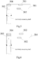
- Fig. 5 a schematic structural view of a door handle according to an embodiment of the present disclosure is shown, and as shown in Fig. 5 , the door handle may be installed corresponding to the lock body connecting shaft of the safety door lock, and optionally, the lock body connecting shaft of the safety door lock may be the lock body connecting shaft shown in Fig. 1 .
- the door handle includes a handle housing 501, a human body detection sensor 502, a controller 503, a servo assembly 504 and an engaging assembly 505.
- the controller is electrically connected with the human body detection sensor and the servo assembly respectively, and the engaging assembly follows the servo assembly; the engaging assembly includes a first engaging state and a second engaging state; the door handle has a capability of driving the lock body connecting shaft to rotate when the engaging assembly is in the first engaging state; and the door handle has no capability of driving the lock body connecting shaft to rotate when the engaging assembly is in the second engaging state.
- the human body detection sensor, the controller, the servo assembly and the engaging assembly are disposed in the handle housing, and one possible arrangement position of assemblies is shown in Fig. 5 .
- the controller may be electrically connected with the human body detection sensor via the handle housing, and may also be electrically connected with the servo assembly via the handle housing.
- the engaging assembly may also be directly connected with the servo assembly, and when the servo assembly is driven to directly bring the engaging assembly to be switched between the first engaging state and the second engaging state, so that the engaging assembly follows the servo assembly.
- the engaging assembly is in the first engaging state, and the engaging assembly is connected with the lock body connecting shaft. At this time, when the door handle is rotated in the direction of the arrow in Fig. 5 , the door handle may drive the lock body connecting shaft to rotate.
- Fig. 6 a schematic structural view of a door handle according to an embodiment of the disclosure is shown, and as shown in Fig. 6 , the door handle includes a handle housing 501, a human body detection sensor 502, a controller 503, a servo assembly 504 and an engaging assembly 505.
- the engaging assembly is in a second engaging state, and the engaging assembly is separated from the lock body connecting shaft, and at this time, the lock body connecting shaft cannot be driven to rotate when the door handle is rotated in the direction of the arrow in Fig. 6 .
- the engaging assembly may rotate with the handle housing, and the engaging assembly is disposed corresponding to the lock body connecting shaft.
- meshing structures are correspondingly disposed on the above-mentioned engaging assembly and the lock body connecting shaft.
- a first meshing structure is disposed on one end of the engaging assembly close to the lock body connecting shaft
- a second meshing structure is correspondingly disposed on one end of the lock body connecting shaft close to the engaging assembly
- the first meshing structure and the second meshing structure may be meshed each other (at the first engaging state at this time), so that the first meshing structure may drive the lock body connecting shaft to rotate with the second meshing structure when the engaging assembly rotates.
- the engaging assembly when the engaging assembly is meshed with the lock body connecting shaft, the handle housing is rotated to drive the engaging assembly to rotate, and the engaging assembly and the lock body connecting shaft are meshed to drive the lock body connecting shaft to rotate, so that unlocking is realized.
- the engaging assembly when the engaging assembly is separated from the lock body connecting shaft, the engaging assembly may be driven to rotate when the handle housing is rotated, however, the engaging assembly is separated from the lock body connecting shaft and cannot drive the lock body connecting shaft to rotate, so that rotation of the door handle cannot realize unlocking at this time.
- the controller in the embodiment of the present disclosure may be used to instruct the servo assembly to control the engaging assembly to enter the first engaging state (as shown in Fig. 5 ) when a human body is detected according to the sensor data of the human body detection sensor. And, the servo assembly is instructed to control the engaging assembly to enter a second engaging state (as shown in Fig. 6 ) when no human body is detected according to the sensor data of the human body detection sensor.
- the operation of the controller in this embodiment is similar to that of the controller in the above embodiment, and will not be repeated herein.
- the arrangement position of the controller in this embodiment may also refer to the arrangement position of the controller in the above embodiment.
- the servo assembly directly controls the engaging assembly to enter the first engaging state or the second engaging state, and in one possible implementation, i.e., the engaging assembly is designed as a part of the servo assembly, which should also be within the protection scope of the present disclosure.
- the operation of the human body detection sensor in this embodiment is also similar to the operation of the human body detection sensor in the above embodiment, and various types of the human body detection sensor may also refer to the description in the above embodiment, which is not repeated herein.
- the door handle provided by the present disclosure is installed corresponding to a lock body connecting shaft of the safety door lock.
- the door handle includes a human body detection sensor, a controller, a servo assembly and an engaging assembly.
- the controller is respectively electrically connected with the human body detection sensor and the servo assembly, and the engaging assembly follows the servo assembly.
- the engaging assembly includes a first engaging state and a second engaging state. When the engaging assembly is in the first engaging state, the door handle has the capability of driving the lock body connecting shaft to rotate; and when the engaging assembly is in the second engaging state, the door handle has no capability of driving the lock body connecting shaft to rotate.
- the present disclosure uses cooperation of the human body detection sensor and the servo assembly, so that the servo assembly controls the engaging assembly to be in the first engaged state or the second engaged state, and the door handle has the capability of driving the locking body to rotate when the engaging assembly is in the first engaged state, so that the user can twist the door handle and drive the lock body to rotate, so as to unlock and open the door without extra mechanical switches, and thus the present disclosure simultaneously possesses the function of preventing from unlocking through a peephole and improves the efficiency of opening the door.
- the door handle may not have the capability of driving the lock body connecting shaft to rotate in the first engaging state corresponding to Figs. 3 and 5 , and the door handle has the capability of driving the lock body connecting shaft to rotate in the second engaging state corresponding to Figs. 4 and 6 .
- the door handle has the capability of driving the locking body to rotate, and in a case that the first meshing structure disposed on one end of the engaging assembly close to the lock body connecting shaft is meshed with the second meshing structure disposed on one end of the lock body connecting shaft close to the engaging assembly, the door handle has no capability of driving the locking body to rotate.
- the embodiments of the present disclosure are not limited thereto.
- the door handle may not drive the lock body connecting shaft to rotate by the engaging assembly, i.e., the door handle may be directly connected with the lock body connecting shaft, and when the door handle rotates, the lock body connecting shaft is driven to rotate.
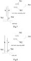
- Fig. 7 a schematic structural view of a door handle according to an embodiment of the present disclosure is shown, and as shown in Fig. 7 , the door handle may be installed corresponding to the lock body connecting shaft of the safety door lock, and optionally, the lock body connecting shaft of the safety door lock may be the lock body connecting shaft shown in Fig. 1 .
- the door handle includes a handle housing 701, a human body detection sensor 702, a controller 703, a servo assembly 704, and an engaging assembly 705.
- the controller is electrically connected with the human body detection sensor and the servo assembly respectively, and the engaging assembly follows the servo assembly; the engaging assembly includes a first engaging state and a second engaging state; the door handle has the capability of rotating when the engaging assembly is in a first engaging state; and the door handle has no capability of rotating when the engaging assembly is in the second engaging state.
- the human body detection sensor, the controller, the servo assembly and the engaging assembly are disposed in the handle housing, and one possible arrangement position of assemblies is shown in Fig. 7 .
- the controller may be electrically connected with the human body detection sensor via the handle housing, and may also be electrically connected with the servo assembly via the handle housing.
- the engaging assembly may also be directly connected with the servo assembly, and when the servo assembly is driven to directly bring the engaging assembly to be switched between the first engaging state and the second engaging state, so that the engaging assembly follows the servo assembly.
- the engaging assembly is in a first engaging state, and the engaging assembly and the lock body are connected with each other, and at this time, when the door handle is rotated in the direction of the arrow shown in Fig. 7 , the door handle cannot be rotated together with the lock body connecting shaft.
- Fig. 8 which is a schematic structural view of a door handle according to an embodiment of the present disclosure, the door handle includes a handle housing 701, a human body detection sensor 702, a controller 703, a servo assembly 704, and an engaging assembly 705. As shown in Fig.
- the engaging assembly is in the second engaging state, and the engaging assembly and the lock body are separated from each other, and at this time, when the door handle is rotated in the direction of the arrow shown in Fig. 8 , the door handle may be rotated together with the lock body connecting shaft.
- a meshing structure is correspondingly disposed between the engaging assembly and the lock body.
- a first meshing structure is disposed on one end of the engaging assembly close to the lock body, and a second meshing structure is correspondingly disposed on one end of the lock body close to the engaging assembly, and the first meshing structure may be meshed with the second meshing structure (at the first engaging state at this time).
- the door handle may be locked through first meshing structure and second meshing structure, so that the door handle may not be rotated with the lock body connecting shaft.
- the first meshing structure is meshed with the second meshing structure on one end of the lock body close to the engaging assembly.
- the first meshing structure when the engaging assembly is in the first engaging state, the first meshing structure is separated from the second meshing structure on one end of the lock body close to the engaging assembly.
- the separation of the first meshing structure and the second meshing structure enables the door handle to rotate together with the lock body connecting shaft.
- the controller in the embodiment of the present disclosure may be used to instruct the servo assembly to control the engaging assembly to enter the first engaging state (as shown in Fig. 8 ) when a human body is detected according to the sensor data of the human body detection sensor. And, the servo assembly is instructed to control the engaging assembly to enter a second engaging state (as shown in Fig. 7 ) when no human body is detected according to the sensor data of the human body detection sensor.
- the operation of the controller in this embodiment is similar to that of the controller in the above embodiment, and will not be repeated herein.
- the arrangement position of the controller in this embodiment may also refer to the arrangement position of the controller in the above embodiment.
- the operation of the human body detection sensor in this embodiment is also similar to the operation of the human body detection sensor in the above embodiment, and various types of the human body detection sensor may also refer to the description in the above embodiment, which is not repeated herein.
- the door handle provided by the present disclosure is installed corresponding to a lock body connecting shaft of the safety door lock.
- the door handle includes a human body detection sensor, a controller, a servo assembly and an engaging assembly.
- the controller is respectively electrically connected with the human body detection sensor and the servo assembly, and the engaging assembly follows the servo assembly.
- the engaging assembly includes a first engaging state and a second engaging state. When the engaging assembly is in the first engaging state, the door handle has the capability of driving the lock body connecting shaft to rotate; and when the engaging assembly is in the second engaging state, the door handle has no capability of driving the lock body connecting shaft to rotate.
- the present disclosure uses cooperation of the human body detection sensor and the servo assembly, so that the servo assembly controls the engaging assembly to be in the first engaged state or the second engaged state, and the door handle has the capability of driving the locking body to rotate when the engaging assembly is in the first engaged state, so that the user can twist the door handle and drive the lock body to rotate, so as to unlock and open the door without extra mechanical switches, and thus the present disclosure simultaneously possesses the function of preventing from unlocking through a peephole and improves the efficiency of opening the door.
- a method flowchart of a control method of a door handle according to an embodiment of the present disclosure is shown, and the method may be performed by a controller in the door handle shown in the above embodiments.
- the control method of the door handle may include: step 901: receiving sensor data of the human body detection sensor.
- the controller may receive the sensor data transmitted from the human body detection sensor and detect the sensor data.
- the controller may transmit the sensor data through an electrical connection circuit between the human body detection sensors.
- the sensor data is sent to the controller, and the controller detects whether the sensor data belongs to the sensor data of the human body.
- the human body detection sensor used in the above-mentioned door handle may include at least one of the following sensors: a human body heat release infrared sensor disposed on the handle housing; a finger vein sensor disposed on the handle housing; a fingerprint sensor disposed on the handle housing; a touch sensor disposed on the handle housing; a face detection sensor disposed outside the handle housing; and an iris detection sensor disposed outside the handle housing.
- the human body detection sensor on the door handle may generate corresponding sensor data by the hand and transmit the sensor data to the controller.
- the human body detection sensor is an iris detection sensor
- the iris detection sensor may receive iris information of the user, generate corresponding sensor data and send the sensor data to the controller. Accordingly, the controller receives sensor data of various human body detection sensors.
- the method further includes step 902: instructing the servo assembly to control the engaging assembly to enter a first engaging state when a human body is detected according to the sensor data.
- a control instruction is sent to the servo assembly to instruct the servo assembly to drive, so that the engaging assembly is controlled by the servo assembly to enter a first engaging state.
- forms of the servo assembly and the engaging assembly may refer to the description in the above embodiments, and are not repeated herein.
- a first meshing structure is disposed on one end of the engaging assembly close to the lock body connecting shaft; and the meshing structure is meshed with the second meshing structure on one end of the lock body connecting shaft close to the engaging assembly when the engaging assembly is in the first engaging state. That is, when the human body is detected according to the sensor data of the human body detection sensor, the controller may instruct the servo assembly to control the engaging assembly to move in a direction approaching the connecting shaft of the lock body so that the engaging assembly enters the first engaging state, such as the process from Fig. 4 to Fig. 3 , or from the process of Fig. 6 to Fig. 5 as mentioned above; when the engaging assembly is in the first engaging state, the door handle has the capability of driving the lock body connecting shaft to rotate.
- the controller may control the engaging assembly to enter the first engaging state shown in Fig. 8 , and the first meshing structure is separated from the second meshing structure on one end of the lock body close to the engaging assembly.
- the door handle has the capability of driving the lock body connecting shaft to rotate.
- the method further includes step 903: instructing the servo assembly to control the engaging assembly to enter a second engaging state when no human body is detected according to the sensor data.
- the controller When no human body is detected by the controller according to the received sensor data, the controller sends a control instruction to the servo assembly to instruct the servo assembly to drive, so that the engaging assembly is controlled to enter the second engaging state through the servo assembly.
- the controller may instruct the servo assembly to control the engaging assembly to move in a direction away from the lock body connecting shaft, so that the engaging assembly enters the second engaging state, such as the process from Fig. 3 to Fig. 4 , or the process from Fig. 5 to Fig. 6 ; and when the engaging assembly is in the second engaging state, the door handle has no the capability of driving the lock body connecting shaft to rotate.
- the controller may control the engaging assembly to enter the second engaging state shown in Fig. 7 , and the first meshing structure is meshed with the second meshing structure on one end of the lock body close to the engaging assembly.
- the door handle has no capability of driving the lock body connecting shaft to rotate.
- the door handle provided by the present disclosure is installed corresponding to a lock body connecting shaft of the safety door lock.
- the door handle includes a human body detection sensor, a controller, a servo assembly and an engaging assembly.
- the controller is respectively electrically connected with the human body detection sensor and the servo assembly, and the engaging assembly follows the servo assembly.
- the engaging assembly includes a first engaging state and a second engaging state. When the engaging assembly is in the first engaging state, the door handle has the capability of driving the lock body connecting shaft to rotate; and when the engaging assembly is in the second engaging state, the door handle has no capability of driving the lock body connecting shaft to rotate.
- the present disclosure uses cooperation of the human body detection sensor and the servo assembly, so that the servo assembly controls the engaging assembly to be in the first engaged state or the second engaged state, and the door handle has the capability of driving the locking body to rotate when the engaging assembly is in the first engaged state, so that the user can twist the door handle and drive the lock body to rotate, so as to unlock and open the door without extra mechanical switches, and thus the present disclosure simultaneously possesses the function of preventing from unlocking through a peephole and improves the efficiency of opening the door.
- a block diagram of a door handle control device according to an embodiment of the disclosure is shown.
- the method may be used in the controller of the door handle shown in the various embodiments described above, and as shown in Fig. 10 , the door handle control device may include the following modules:
- a first meshing structure is provided on one end of the engaging assembly close to the lock body connecting shaft; the first meshing structure is meshed with a second meshing structure on one end of the lock body connecting shaft close to the engaging assembly when the engaging assembly is in the first engaging state; and the first meshing structure is separated from a second meshing structure on one end of the lock body connecting shaft close to the engaging assembly when the engaging assembly is in the second engaging state; the first control module is used to:
- the human body detection sensor includes at least one of the following sensors:
- the functions described in the embodiments of the present disclosure may be implemented in hardware, software, firmware, or any combination thereof in one or more of the examples described above.
- these functions may be stored in a computer-readable medium or transmitted as one or more instructions or codes on a computer-readable medium.
- the computer-readable medium includes both a computer storage medium and a communication medium including any medium that facilitates transfer of a computer program from one place to another.
- the storage medium may be any available medium that can be accessed by a general or specific computer.
- the embodiments of the present disclosure also provide a computer-readable storage medium having executable instructions embodied therein that are invoked by a processor to implement the control method of the door handle described above.
- a schematic structural view of a safety door lock according to an embodiment of the disclosure is shown, and as shown in Fig. 11 , the safety door lock includes a door handle 1101, a lock body connecting shaft 1102, and a lock body 1103.
- the door handle 1101 may be any door handle provided in the above embodiments, and optionally, the door handle may be provided with the human body detection sensor and the controller in the above embodiments.
- the controller detects the sensor data transmitted by the human body detection sensor, and optionally, the controller may control the door handle in the manner described in the above embodiments.
- the human body detection sensor may transmit the sensor data to the controller, and accordingly, when the human body is detected by the controller, the controller may control the servo assembly in the door handle to work, so that when the user rotates the door handle, the lock body connecting shaft may also rotate along with the door handle, and the lock body is unlocked.
- the controller installed in the door handle may also be disposed in the lock body of the safety door lock or disposed in the lock body connecting shaft, which is not limited by the embodiments of the present disclosure.
- the embodiments of the present disclosure also provide a schematic structural view of a safety door on which at least one safety door lock as shown in Fig. 11 is installed.
- the sensor data may be sent to the controller through the human body detection sensor.
- the human body detection sensor detects the human body.
- the state that the door handle has no the capability of driving the lock body connecting shaft to rotate is changed into the state that the door handle has the capability of driving the lock body connecting shaft to rotate, so that the safety door lock may be opened when the user rotates the door handle, thereby achieving the effect of door opening.
- an iris detection sensor or a face detection sensor is disposed on the safety door, i.e., when the human body detection sensor is an iris detection sensor or a face detection sensor, it may be disposed on the safety door.
Landscapes
- Engineering & Computer Science (AREA)
- Physics & Mathematics (AREA)
- General Physics & Mathematics (AREA)
- Mechanical Engineering (AREA)
- Human Computer Interaction (AREA)
- Multimedia (AREA)
- Theoretical Computer Science (AREA)
- Lock And Its Accessories (AREA)
Abstract
Description
- The present disclosure relates to the technical field of smart homes, in particular to a door handle, a control method of a door handle, a device storage medium, a safety door lock and a safety door.
- With the development of science and technology, people pay more and more attention to the safety problem in daily life, and most door locks are provided with peepholes so as to observe conditions outside the door. However, the presence of peephole on the door may cause some safety problems.
- In the related art, in order to prevent a lawless person from opening a door through a peephole, a mechanical switch is added to an indoor door handle, and a pressing direction of the mechanical switch is perpendicular to a twisting direction of a traditional door handle. When the door is opened from the indoor, the mechanical switch needs to be pressed and the door handle needs to be twisted, so that the door can be opened from the indoor, thereby preventing from unlocking through the peephole and ensuring the indoor safety.
- The embodiments of the present disclosure provide a door handle, a control method of a door handle, a device storage medium, a safety door lock and a safety door. The technical solution is as follows.
- According to a first aspect of the present disclosure, a door handle is provided. The door handle is installed corresponding to a lock body connecting shaft of a safety door lock. The door handle includes a human body detection sensor, a controller, a servo assembly and an engaging assembly;
wherein the controller is electrically connected with the human body detection sensor and the servo assembly, respectively, and the engaging assembly follows the servo assembly;
the engaging assembly includes a first engaging state and a second engaging state; and
wherein the door handle has a capability of driving the lock body connecting shaft to rotate when the engaging assembly is in the first engaging state; and the door handle has no capability of driving the lock body connecting shaft to rotate when the engaging assembly is in the second engaging state. - Optionally, the controller is used for instructing the servo assembly to control the engaging assembly to enter the first engaging state when a human body is detected according to sensor data of the human body detection sensor; and
the controller is also used for instructing the servo assembly to control the engaging assembly to enter the second engaging state when no human body is detected according to the sensor data of the human body detection sensor. - Optionally, the engaging assembly rotates with a handle housing of the door handle and the engaging assembly is disposed in correspondence with the lock body connecting shaft;
the engaging assembly is meshed with the lock body connecting shaft when the engaging assembly is in the first engaging state; and
the engaging assembly is separated from the lock body connecting shaft when the engaging assembly is in the second engaging state. - Optionally, a first meshing structure is provided on one end of the engaging assembly close to the lock body connecting shaft;
the first meshing structure is meshed with a second meshing structure on one end of the lock body connecting shaft close to the engaging assembly when the engaging assembly is in the first engaging state; and
the first meshing structure is separated from the second meshing structure on one end of the lock body connecting shaft close to the engaging assembly when the engaging assembly is in the second engaging state. - Optionally, the controller is used to instruct the servo assembly to control the engaging assembly to move towards a direction close to the lock body connecting shaft when a human body is detected according to sensor data of the human body detection sensor, so that the engaging assembly enters the first engaging state; and
the controller is also used to instruct the servo assembly to control the engaging assembly to move towards a direction away from the lock body connecting shaft when no human body is detected according to the sensor data of the human body detection sensor, so that the engaging assembly enters the second engaging state. - Optionally, the human body detection sensor includes at least one of the following sensors:
- a human body heat release infrared sensor disposed on a handle housing of the door handle;
- a finger vein sensor disposed on the handle housing of the door handle;
- a fingerprint sensor disposed on the handle housing of the door handle;
- a touch sensor disposed on the handle housing of the door handle;
- a face detection sensor disposed outside the handle housing of the door handle; and
- an iris detection sensor disposed outside the handle housing of the door handle.
- According to a second aspect of the present disclosure, a control method of a door handle is provided, which is performed by a controller in a door handle according to any one of embodiments of the first aspect described above. The method includes:
- receiving sensor data of a human body detection sensor;
- instructing the servo assembly to control the engaging assembly to enter a first engaging state when a human body is detected according to the sensor data; and
- instructing the servo assembly to control the engaging assembly to enter a second engaging state when no human body is detected according to the sensor data;
- wherein the door handle has a capability of driving the lock body connecting shaft to rotate when the engaging assembly is in the first engaging state; and the door handle has no the capability of driving the lock body connecting shaft to rotate when the engaging assembly is in the second engaging state.
- Optionally, a first meshing structure is provided on one end of the engaging assembly close to the lock body connecting shaft; when the engaging assembly is in the first engaging state, the first meshing structure is meshed with a second meshing structure on one end of the lock body connecting shaft close to the engaging assembly; and when the engaging assembly is in the second engaging state, the first meshing structure is separated from a second meshing structure on one end of the lock body connecting shaft close to the engaging assembly;
instructing the servo assembly to control the engaging assembly to enter the first engaging state when the human body is detected according to the sensor data includes: - when the human body is detected according to the sensor data of the human body detection sensor, instructing the servo assembly to control the engaging assembly to move towards a direction close to the lock body connecting shaft, so that the engaging assembly enters the first engaging state; and
- instructing the servo assembly to control the engaging assembly to enter the second engaging state when no human body is detected according to the sensor data includes:
when no human body is detected according to the sensor data of the human body detection sensor, instructing the servo assembly to control the engaging assembly to move towards a direction away from the lock body connecting shaft, so that the engaging assembly enters the second engaging state. - Optionally, the human body detection sensor includes at least one of the following sensors:
- a human body heat release infrared sensor disposed on a handle housing of the door handle;
- a finger vein sensor disposed on the handle housing of the door handle;
- a fingerprint sensor disposed on the handle housing of the door handle;
- a touch sensor disposed on the handle housing of the door handle;
- a face detection sensor disposed outside the handle housing of the door handle; and
- an iris detection sensor disposed outside the handle housing of the door handle.
- According to a third aspect of the present disclosure, a door handle control device used in a controller in a door handle according to any one of embodiments of the first aspect is provided. The device includes:
- a data receiving module used to receive sensor data of the human body detection sensor;
- a first control module used to instruct the servo assembly to control the engaging assembly to enter a first engaging state when a human body is detected according to the sensor data; and
- a second control module used to instruct the servo assembly to control the engaging assembly to enter a second engaging state when no human body is detected according to the sensor data;
- wherein the door handle has a capability of driving the lock body connecting shaft to rotate when the engaging assembly is in the first engaging state; and the door handle has no the capability of driving the lock body connecting shaft to rotate when the engaging assembly is in the second engaging state.
- Optionally, a first meshing structure is provided on one end of the engaging assembly close to the lock body connecting shaft; the first meshing structure is meshed with a second meshing structure on one end of the lock body connecting shaft close to the engaging assembly when the engaging assembly is in the first engaging state; and the first meshing structure is separated from a second meshing structure on one end of the lock body connecting shaft close to the engaging assembly when the engaging assembly is in the second engaging state;
the first control module is used to: - instruct the servo assembly to control the engaging assembly to move towards a direction close to the lock body connecting shaft when the human body is detected according to the sensor data of the human body detection sensor, so that the engaging assembly enters the first engaging state; and
- the second control module is used to:
instruct the servo assembly to control the engaging assembly to move in a direction away from the lock body connecting shaft when the human body is detected according to the sensor data of the human body detection sensor, so that the engaging assembly enters the second engaging state. - Optionally, the human body detection sensor includes at least one of the following sensors:
- a human body heat release infrared sensor disposed on a handle housing of the door handle;
- a finger vein sensor disposed on the handle housing of the door handle;
- a fingerprint sensor disposed on the handle housing of the door handle;
- a touch sensor disposed on the handle housing of the door handle;
- a face detection sensor disposed outside the handle housing of the door handle; and
- an iris detection sensor disposed outside the handle housing of the door handle.
- According to a fourth aspect of the present disclosure, a computer-readable storage medium having executable instructions which are invoked by a processor to implement a control method of a door handle of any one of embodiments of the second aspect is provided.
- According to a fifth aspect of the present disclosure, a safety door lock including a door handle and a lock body connecting shaft is provided, and the door handle is a door handle according to any one of embodiments of the first aspect.
- According to a sixth aspect of the present disclosure, a safety door including at least one safety door lock according to the fifth aspect is provided.
- The technical solution provided by the embodiments of the present disclosure at least includes the following beneficial effects.
- The door handle provided by the present disclosure is installed corresponding to a lock body connecting shaft of the safety door lock. The door handle includes a human body detection sensor, a controller, a servo assembly and an engaging assembly. The controller is respectively electrically connected with the human body detection sensor and the servo assembly, and the engaging assembly follows the servo assembly. The engaging assembly includes a first engaging state and a second engaging state. When the engaging assembly is in the first engaging state, the door handle has the capability of driving the lock body connecting shaft to rotate; and when the engaging assembly is in the second engaging state, the door handle has no capability of driving the lock body connecting shaft to rotate. The present disclosure uses cooperation of the human body detection sensor and the servo assembly, so that the servo assembly controls the engaging assembly to be in the first engaged state or the second engaged state, and the door handle has the capability of driving the locking body to rotate when the engaging assembly is in the first engaged state, so that the user can twist the door handle and drive the lock body to rotate, so as to unlock and open the door without extra mechanical switches, and thus the present disclosure simultaneously possesses the function of preventing from unlocking through a peephole and improves the efficiency of opening the door.
- It should be understood that both the foregoing general description and the following detailed description are exemplary and explanatory only and are not restrictive of the present disclosure.
- The accompanying drawings, which are incorporated in and constitute part of this specification, illustrate embodiments consistent with the present disclosure and, together with the description, serve to explain the principles of the present disclosure.
-
Fig. 1 is a schematic structural view of an indoor door handle according to an embodiment of the present disclosure; -
Fig. 2 is a schematic structural view of a door handle according to an embodiment of the present disclosure; -
Fig. 3 is a schematic structural view of a door handle according to an embodiment of the present disclosure; -
Fig. 4 is a schematic structural view of a door handle ofFig. 3 according to an embodiment of the present disclosure; -
Fig. 5 is a schematic structural view of a door handle according to an embodiment of the present disclosure; -
Fig. 6 is a schematic structural view of a door handle ofFig. 5 according to an embodiment of the present disclosure; -
Fig. 7 is a schematic structural view of a door handle according to an embodiment of the present disclosure; -
Fig. 8 is a schematic structural view of a door handle ofFig. 7 according to an embodiment of the present disclosure; -
Fig. 9 is a method flow diagram of a control method of a door handle according to an embodiment of the present disclosure; -
Fig. 10 is a device block diagram of a door handle control device according to an embodiment of the present disclosure; and -
Fig. 11 is a schematic structural view of a safety door lock according to an embodiment of the present disclosure. - Reference will now be made in detail to the exemplary embodiments, examples of which are illustrated in the accompanying drawings. When the following description refers to the accompanying drawings, the same numbers in different drawings represent the same or similar elements unless otherwise indicated. The implementations described in the following exemplary embodiments do not represent all implementations consistent with the present disclosure. Rather, they are merely examples of devices and methods consistent with certain aspects of the present disclosure, as detailed in the appended claims.
- The solution provided by the present disclosure can be used in the scenario that a user opens the door from the indoor in daily life, and for convenience of understanding, some terms and application scenarios related to by the embodiment of the present disclosure are briefly introduced below.
- A peephole refers to a door mirror installed on the door for observing outdoor conditions from the indoor, and commonly called as a cat's eye.
- With the continuous improvement of people's living standard, the user pays more and more attention to indoor safety, and people usually install a peephole on the door in the room, so that when someone knocks the door, the outdoor condition may be confirmed from indoor earlier, thereby confirming whether the door would be opened. However, the peephole also has certain safety hazards. For example, the peephole can be pried out from the outside, so that the door can be opened from the indoor through the peephole.
- In the related art, in order to prevent from opening the door from the indoor through the peephole, a mechanical switch is added to the indoor door handle, and when the door is opened from the indoor, the door handle needs to be rotated in a conventional twisting manner, and the mechanical switch needs to be pressed down to open the door from the indoor. Referring to
Fig. 1 , a schematic structural view of an indoor door handle according to an embodiment of the present disclosure is shown. As shown inFig. 1(a) , which is a front view of an indoor door handle, adoor handle 101 and amechanical switch 102 are included. As shown inFig. 1 (b) , which is a top view of the indoor door handle including adoor handle 101, amechanical switch 102, and a lockbody connecting shaft 103. The lockbody connecting shaft 103 may be connected with a lock core of a lock installed on the door, and the lock is unlocked by the rotation of the lock body connecting shaft. When the user wants to open the door from the indoor, the user may press themechanical switch 102 in a direction of arrow (pressing direction) shown inFig. 1(b) , and then turns thedoor handle 101 in the direction of the arrow (rotating direction) shown inFig. 1(a) . Then, thedoor handle 101 is twisted and the lockbody connecting shaft 103 is rotated in the same direction as the rotating direction of the door handle, thereby unlocking the lock installed on the door, and thus opening the door. - When the user opens the door from the indoor, it is necessary to hold the door handle and additionally press the mechanical switch, so that operation steps of opening the door from the indoor become complicated, and the door opening efficiency is reduced.
- In order to solve the above-described problems, the present disclosure provides a door handle. Referring to
Fig. 2 , a schematic structural view of a door handle according to an embodiment of the present disclosure is shown. As shown inFig. 2 , the door handle may be installed corresponding to the lock body connecting shaft of the safety door lock, and optionally, the lock body connecting shaft of the safety door lock may be the lock body connecting shaft shown inFig. 1 . As shown inFig. 2 , the door handle includes ahandle housing 201, a humanbody detection sensor 202, acontroller 203, aservo assembly 204 and an engagingassembly 205;
wherein thecontroller 203 is electrically connected with the humanbody detection sensor 202 and theservo assembly 204, respectively, and the engagingassembly 205 follows theservo assembly 204;
the engagingassembly 205 includes a first engaging state and a second engaging state;
wherein the door handle has a capability of driving the lock body connecting shaft to rotate when the engagingassembly 205 is in the first engaging state; and the door handle has no capability of driving the lock body connecting shaft to rotate when the engagingassembly 205 is in the second engaging state. - Optionally, the
controller 203 is used to instruct theservo assembly 204 to control the engagingassembly 205 to enter the first engaging state when a human body is detected according to the sensor data of the humanbody detection sensor 202; and
thecontroller 203 is used to instruct theservo assembly 204 to control the engagingassembly 205 to enter the second engaging state when no human body is detected according to the sensor data of the humanbody detection sensor 202. - Optionally, the engaging
assembly 205 rotates with thehandle housing 201, and the engagingassembly 205 is disposed in correspondence with the lock body connecting shaft;
the engagingassembly 205 is meshed with the lock body connecting shaft when the engagingassembly 205 is in the first engaging state; and
the engagingassembly 205 is separated from the lock body connecting shaft when the engagingassembly 205 is in the second engaging state. - Optionally, a first meshing structure is provided on one end of the engaging
assembly 205 close to the lock body connecting shaft;
the first meshing structure is meshed with a second meshing structure on one end of the lock body connecting shaft close to the engagingassembly 205 when the engagingassembly 205 is in the first engaging state; and
the first meshing structure is separated from the second meshing structure on one end of the lock body connecting shaft close to the engagingassembly 205 when the engagingassembly 205 is in the second engaging state. - Optionally, the
controller 203 is used to instruct theservo assembly 204 to control the engagingassembly 205 to move towards a direction close to the lock body connecting shaft when a human body is detected according to sensor data of the humanbody detection sensor 202, so that the engagingassembly 205 enters the first engaging state; and
thecontroller 203 is also used to instruct theservo assembly 204 to control the engagingassembly 205 to move towards a direction away from the lock body connecting shaft when no human body is detected according to the sensor data of the humanbody detection sensor 202, so that the engagingassembly 205 enters the second engaging state. - Optionally, the human
body detection sensor 202 includes at least one of the following sensors: - a human body heat release infrared sensor disposed on the
handle housing 201 of the door handle; - a finger vein sensor disposed on the
handle housing 201 of the door handle; - a fingerprint sensor disposed on the
handle housing 201 of the door handle; - a touch sensor disposed on the
handle housing 201 of the door handle; - a face detection sensor disposed outside the
handle housing 201 of the door handle; and - an iris detection sensor disposed outside the
handle housing 201 of the door handle. - In conclusion, the door handle provided by the present disclosure is installed corresponding to a lock body connecting shaft of the safety door lock. The door handle includes a human body detection sensor, a controller, a servo assembly and an engaging assembly. The controller is respectively electrically connected with the human body detection sensor and the servo assembly, and the engaging assembly follows the servo assembly. The engaging assembly includes a first engaging state and a second engaging state. When the engaging assembly is in the first engaging state, the door handle has the capability of driving the lock body connecting shaft to rotate; and when the engaging assembly is in the second engaging state, the door handle has no capability of driving the lock body connecting shaft to rotate. The present disclosure uses cooperation of the human body detection sensor and the servo assembly, so that the servo assembly controls the engaging assembly to be in the first engaged state or the second engaged state, and the door handle has the capability of driving the locking body to rotate when the engaging assembly is in the first engaged state, so that the user can twist the door handle and drive the lock body to rotate, so as to unlock and open the door without extra mechanical switches, and thus the present disclosure simultaneously possesses the function of preventing from unlocking through a peephole and improves the efficiency of opening the door.
- In one possible implementation, the servo assembly may include a motor and a motor drive shaft, and the first engaging state and the second engaging state of the engaging assembly are achieved by driving the motor drive shaft by the motor in the servo assembly. Referring to
Fig. 3 , a schematic structural view of a door handle according to an embodiment of the present disclosure is shown. As shown inFig. 3 , the door handle may be installed corresponding to the lock body connecting shaft of the safety door lock, and optionally, the lock body connecting shaft of the safety door lock may be the lock body connecting shaft shown inFig. 1 . As shown inFig. 3 , the door handle includes ahandle housing 301, a humanbody detection sensor 302, acontroller 303, aservo assembly 304 and an engagingassembly 305. - The controller is electrically connected with the human body detection sensor and the servo assembly respectively, and the engaging assembly follows the servo assembly; the engaging assembly includes a first engaging state and a second engaging state; the door handle has a capability of driving the lock body connecting shaft to rotate when the engaging assembly is in the first engaging state; and the door handle has no capability of driving the lock body connecting shaft to rotate when the engaging assembly is in the second engaging state.
- As shown in
Fig. 3 , the human body detection sensor, the controller, the servo assembly and the engaging assembly are disposed in the handle housing, and one possible arrangement position of assemblies is shown inFig. 3 . The controller may be electrically connected with the human body detection sensor via the handle housing, and may also be electrically connected with the servo assembly via the handle housing. Optionally, as shown inFig. 3 , the servo assembly may further include amotor 304b and amotor driving shaft 304a, and the engaging assembly is controlled by the motor driving shaft in the servo assembly. Optionally, the motor driving shaft may be screwed with the motor via threads, and the motor may control the movement of the motor driving shaft by screwing between the motor itself and the motor driving shaft, so that the engaging assembly follows the motor driving shaft. - As shown in
Fig. 3 , the engaging assembly is in the first engaging state, and the engaging assembly is connected with the lock body connecting shaft. At this time, when the door handle is rotated in the direction of the arrow inFig. 3 , the door handle may drive the lock body connecting shaft to rotate. Referring toFig. 4 , a schematic structural view of a door handle according to an embodiment of the disclosure is shown, and as shown inFig. 4 , the door handle includes ahandle housing 301, a humanbody detection sensor 302, acontroller 303, aservo assembly 304 and an engagingassembly 305. As shown inFig. 4 , the engaging assembly is in a second engaging state, and the engaging assembly is separated from the lock body connecting shaft, and at this time, the lock body connecting shaft cannot be driven to rotate when the door handle is rotated in the direction of the arrow inFig. 4 . - In one possible implementation, as shown in
Figs. 3 or 4 , the engaging assembly may rotate with the handle housing, and the engaging assembly is disposed corresponding to the lock body connecting shaft. Optionally, meshing structures are correspondingly disposed on the above-mentioned engaging assembly and the lock body connecting shaft. A first meshing structure is disposed on one end of the engaging assembly close to the lock body connecting shaft, a second meshing structure is correspondingly disposed on one end of the lock body connecting shaft close to the engaging assembly, and the first meshing structure and the second meshing structure may be meshed each other, so that the first meshing structure may drive the lock body connecting shaft to rotate with the second meshing structure when the engaging assembly rotates. As shown inFig. 3 , when the engaging assembly is in the first engaging state, the first meshing structure is meshed with the second meshing structure on one end of the lock body connecting shaft close to the engaging assembly; as shown inFig. 4 , when the engaging assembly is in the second engaging state, the first meshing structure is separated from the second meshing structure on one end of the lock body connecting shaft close to the engaging assembly. - Optionally, when the engaging assembly is in the first engaging state, the engaging assembly is meshed with the lock body connecting shaft; and when the engaging assembly is in the second engaging state, the engaging assembly is separated from the lock body connecting shaft. As shown in
Fig. 3 , when the engaging assembly is meshed with the lock body connecting shaft, the handle housing is rotated to drive the engaging assembly to rotate, and the engaging assembly and the lock body connecting shaft are meshed to drive the lock body connecting shaft to rotate, so that unlocking is realized. As shown inFig. 4 , when the engaging assembly is separated from the lock body connecting shaft, the engaging assembly may be driven to rotate when the handle housing is rotated, however, the engaging assembly is separated from the lock body connecting shaft and cannot drive the lock body connecting shaft to rotate, so that rotation of the door handle cannot realize unlocking at this time. - The controller may be provided inside the handle housing or may be provided at a location other than the handle housing, for example, inside a lock of a safety door lock, inside a door in which the safety door lock is installed, or the like. That is, the controller may be electrically connected with the human body detection sensor and the servo assembly, and may receive sensor data of the human body detection sensor and control the servo assembly. The specific arrangement position of the controller is not limited in the embodiments of the present disclosure.
- Optionally, the controller may be used to instruct the servo assembly to control the engaging assembly to enter the first engaging state when the human body is detected according to the sensor data of the human body detection sensor. For example, taking a sensor disposed on a handle housing of a door handle as an example of the human body detection sensor, when the user holds the door handle, the human body detection sensor may receive information of the user's hand, generate sensor data, and transmit the generated sensor data to a controller by electrical connection with the controller, then the controller analyzes the sensor data according to the received sensor data, and sends a control signal to a servo assembly when the human body information is detected so as to instruct the servo assembly to control an engaging assembly to enter a first engaging state. As shown in
Fig. 4 , when the controller detects the presence of a human body according to the received sensor data, it may transmit a control signal to the servo assembly to control the motor in the servo assembly to start operation, thereby changing the motor drive shaft from the state shown inFig. 4 to the state shown inFig. 3 , and controlling the engaging assembly to change from the second engaging state to the first engaging state. - Optionally, the controller may instruct the servo assembly to control the engaging assembly to enter the second engaging state when no human body is detected according to the sensor data of the human body detection sensor. For example, taking a sensor disposed on a handle housing of a door handle as an example of the human body detection sensor, the human body detection sensor continues to receive information during a time that the user holds the door handle to a time that the user releases the door handle, the information that may be received does not include human body information, and in the generated sensor data, there may be no human body information data, so that the human body detection sensor transmits the generated sensor data to the controller by the above electrical connection at this time, and the controller analyzes the sensor data according to the received sensor data. When no human body is detected, the controller sends a control signal to the servo assembly, and instructs the servo assembly to control the engaging assembly to enter the second engaging state. As shown in
Fig. 3 , when the controller detects no human body according to the received sensor data, the controller may transmit a control signal to the servo assembly to control the motor in the servo assembly to start operation, thereby changing the motor drive shaft from the state shown inFig. 3 to the state shown inFig. 4 , and controlling the engaging assembly to change from the first engaging state to the second engaging state. - Optionally, the controller may be used to instruct the servo assembly to control the engaging assembly to move in a direction approaching the lock body connecting shaft when a human body is detected according to the sensor data of the human body detection sensor, so that the engaging assembly enters a first engaging state; that is, in the process of changing the motor drive shaft from the state shown in
Fig. 4 to the state shown inFig. 3 to control the engaging assembly to change from the second engaging state to the first engaging state, the engaging assembly moves in a direction approaching the lock body connecting shaft, so that the engaging assembly may enter the first engaging state. - The controller may be used to instruct the servo assembly to control the engaging assembly to move towards a direction away from the lock body connecting shaft when no human body is detected according to the sensor data of the human body detection sensor, so that the engaging assembly enters the second engaging state. That is, in the process of changing the motor drive shaft from the state shown in
Fig. 3 to the state shown inFig. 4 to control the engaging assembly to change from the first engaging state to the second engaging state, the engaging assembly moves in a direction away from the lock body connecting shaft, so that the engaging assembly may enter the second engaging state. - Optionally, the human body detection sensor used in the above-mentioned door handle may include at least one of the following sensors: a human body heat release infrared sensor disposed on the handle housing; a finger vein sensor disposed on the handle housing; a fingerprint sensor disposed on the handle housing; a touch sensor disposed on the handle housing; a face detection sensor disposed outside the handle housing; and an iris detection sensor disposed outside the handle housing. That is, the human body detection sensor may be disposed on the handle housing, or may be disposed on a safety door lock or a door controlled by the door handle, which is not limited in this embodiment of the present disclosure. The touch sensor may include a resistive touch sensor, a capacitive touch sensor, and a surface acoustic wave touch sensor, and the generated sensor data is transmitted to the controller for detection by the controller, similar to the implementation principle of a touch screen. For example, when the human body detection sensor is a human body heat release infrared sensor, the user holds the door handle by hand, the human body heat release infrared sensor disposed on the handle housing of the door handle may generate sensor data, transmit the generated sensor data to the electrically connected controller, and detect whether a human body exists by the controller according to the sensor data transmitted by the human body detection sensor, thereby instructing the servo assembly to perform a responsive action. Optionally, application principles of other human body detection sensors are also similar, and the detailed description thereof will be omitted herein.
- In conclusion, the door handle provided by the present disclosure is installed corresponding to a lock body connecting shaft of the safety door lock. The door handle includes a human body detection sensor, a controller, a servo assembly and an engaging assembly. The controller is respectively electrically connected with the human body detection sensor and the servo assembly, and the engaging assembly follows the servo assembly. The engaging assembly includes a first engaging state and a second engaging state. When the engaging assembly is in the first engaging state, the door handle has the capability of driving the lock body connecting shaft to rotate; and when the engaging assembly is in the second engaging state, the door handle has no capability of driving the lock body connecting shaft to rotate. The present disclosure uses cooperation of the human body detection sensor and the servo assembly, so that the servo assembly controls the engaging assembly to be in the first engaged state or the second engaged state, and the door handle has the capability of driving the locking body to rotate when the engaging assembly is in the first engaged state, so that the user can twist the door handle and drive the lock body to rotate, so as to unlock and open the door without extra mechanical switches, and thus the present disclosure simultaneously possesses the function of preventing from unlocking through a peephole and improves the efficiency of opening the door.
- In one possible implementation, the servo assembly may directly control the engaging assembly to switch between the first engaging state and the second engaging state. Referring to
Fig. 5 , a schematic structural view of a door handle according to an embodiment of the present disclosure is shown, and as shown inFig. 5 , the door handle may be installed corresponding to the lock body connecting shaft of the safety door lock, and optionally, the lock body connecting shaft of the safety door lock may be the lock body connecting shaft shown inFig. 1 . As shown inFig. 5 , the door handle includes ahandle housing 501, a humanbody detection sensor 502, acontroller 503, aservo assembly 504 and an engagingassembly 505. - The controller is electrically connected with the human body detection sensor and the servo assembly respectively, and the engaging assembly follows the servo assembly; the engaging assembly includes a first engaging state and a second engaging state; the door handle has a capability of driving the lock body connecting shaft to rotate when the engaging assembly is in the first engaging state; and the door handle has no capability of driving the lock body connecting shaft to rotate when the engaging assembly is in the second engaging state.
- The human body detection sensor, the controller, the servo assembly and the engaging assembly are disposed in the handle housing, and one possible arrangement position of assemblies is shown in
Fig. 5 . The controller may be electrically connected with the human body detection sensor via the handle housing, and may also be electrically connected with the servo assembly via the handle housing. The engaging assembly may also be directly connected with the servo assembly, and when the servo assembly is driven to directly bring the engaging assembly to be switched between the first engaging state and the second engaging state, so that the engaging assembly follows the servo assembly. - As shown in
Fig. 5 , the engaging assembly is in the first engaging state, and the engaging assembly is connected with the lock body connecting shaft. At this time, when the door handle is rotated in the direction of the arrow inFig. 5 , the door handle may drive the lock body connecting shaft to rotate. Referring toFig. 6 , a schematic structural view of a door handle according to an embodiment of the disclosure is shown, and as shown inFig. 6 , the door handle includes ahandle housing 501, a humanbody detection sensor 502, acontroller 503, aservo assembly 504 and an engagingassembly 505. As shown inFig. 6 , the engaging assembly is in a second engaging state, and the engaging assembly is separated from the lock body connecting shaft, and at this time, the lock body connecting shaft cannot be driven to rotate when the door handle is rotated in the direction of the arrow inFig. 6 . - In one possible implementation, as shown in
Figs. 5 or 6 , the engaging assembly may rotate with the handle housing, and the engaging assembly is disposed corresponding to the lock body connecting shaft. Optionally, meshing structures are correspondingly disposed on the above-mentioned engaging assembly and the lock body connecting shaft. A first meshing structure is disposed on one end of the engaging assembly close to the lock body connecting shaft, a second meshing structure is correspondingly disposed on one end of the lock body connecting shaft close to the engaging assembly, and the first meshing structure and the second meshing structure may be meshed each other (at the first engaging state at this time), so that the first meshing structure may drive the lock body connecting shaft to rotate with the second meshing structure when the engaging assembly rotates. As shown inFig. 5 , when the engaging assembly is in the first engaging state, the first meshing structure is meshed with the second meshing structure on one end of the lock body connecting shaft close to the engaging assembly; as shown inFig. 6 , when the engaging assembly is in the second engaging state, the first meshing structure is separated from the second meshing structure on one end of the lock body connecting shaft close to the engaging assembly. - As shown in
Fig. 5 , when the engaging assembly is meshed with the lock body connecting shaft, the handle housing is rotated to drive the engaging assembly to rotate, and the engaging assembly and the lock body connecting shaft are meshed to drive the lock body connecting shaft to rotate, so that unlocking is realized. As shown inFig. 6 , when the engaging assembly is separated from the lock body connecting shaft, the engaging assembly may be driven to rotate when the handle housing is rotated, however, the engaging assembly is separated from the lock body connecting shaft and cannot drive the lock body connecting shaft to rotate, so that rotation of the door handle cannot realize unlocking at this time. - Optionally, the controller in the embodiment of the present disclosure may be used to instruct the servo assembly to control the engaging assembly to enter the first engaging state (as shown in
Fig. 5 ) when a human body is detected according to the sensor data of the human body detection sensor. And, the servo assembly is instructed to control the engaging assembly to enter a second engaging state (as shown inFig. 6 ) when no human body is detected according to the sensor data of the human body detection sensor. The operation of the controller in this embodiment is similar to that of the controller in the above embodiment, and will not be repeated herein. In addition, the arrangement position of the controller in this embodiment may also refer to the arrangement position of the controller in the above embodiment. It should be noted that, in this embodiment, the servo assembly directly controls the engaging assembly to enter the first engaging state or the second engaging state, and in one possible implementation, i.e., the engaging assembly is designed as a part of the servo assembly, which should also be within the protection scope of the present disclosure. - Optionally, the operation of the human body detection sensor in this embodiment is also similar to the operation of the human body detection sensor in the above embodiment, and various types of the human body detection sensor may also refer to the description in the above embodiment, which is not repeated herein.
- In conclusion, the door handle provided by the present disclosure is installed corresponding to a lock body connecting shaft of the safety door lock. The door handle includes a human body detection sensor, a controller, a servo assembly and an engaging assembly. The controller is respectively electrically connected with the human body detection sensor and the servo assembly, and the engaging assembly follows the servo assembly. The engaging assembly includes a first engaging state and a second engaging state. When the engaging assembly is in the first engaging state, the door handle has the capability of driving the lock body connecting shaft to rotate; and when the engaging assembly is in the second engaging state, the door handle has no capability of driving the lock body connecting shaft to rotate. The present disclosure uses cooperation of the human body detection sensor and the servo assembly, so that the servo assembly controls the engaging assembly to be in the first engaged state or the second engaged state, and the door handle has the capability of driving the locking body to rotate when the engaging assembly is in the first engaged state, so that the user can twist the door handle and drive the lock body to rotate, so as to unlock and open the door without extra mechanical switches, and thus the present disclosure simultaneously possesses the function of preventing from unlocking through a peephole and improves the efficiency of opening the door.
- It should be noted that in the embodiments shown in
Figs. 3, 4 ,5 and 6 , the door handle may not have the capability of driving the lock body connecting shaft to rotate in the first engaging state corresponding toFigs. 3 and5 , and the door handle has the capability of driving the lock body connecting shaft to rotate in the second engaging state corresponding toFigs. 4 and6 . That is, in a case that the first meshing structure disposed on one end of the engaging assembly close to the lock body connecting shaft is separated from the second meshing structure disposed on one end of the lock body connecting shaft close to the engaging assembly, the door handle has the capability of driving the locking body to rotate, and in a case that the first meshing structure disposed on one end of the engaging assembly close to the lock body connecting shaft is meshed with the second meshing structure disposed on one end of the lock body connecting shaft close to the engaging assembly, the door handle has no capability of driving the locking body to rotate. The embodiments of the present disclosure are not limited thereto. - In one possible implementation, the door handle may not drive the lock body connecting shaft to rotate by the engaging assembly, i.e., the door handle may be directly connected with the lock body connecting shaft, and when the door handle rotates, the lock body connecting shaft is driven to rotate. Referring to
Fig. 7 , a schematic structural view of a door handle according to an embodiment of the present disclosure is shown, and as shown inFig. 7 , the door handle may be installed corresponding to the lock body connecting shaft of the safety door lock, and optionally, the lock body connecting shaft of the safety door lock may be the lock body connecting shaft shown inFig. 1 . As shown inFig. 7 , the door handle includes ahandle housing 701, a humanbody detection sensor 702, acontroller 703, aservo assembly 704, and an engagingassembly 705. - The controller is electrically connected with the human body detection sensor and the servo assembly respectively, and the engaging assembly follows the servo assembly; the engaging assembly includes a first engaging state and a second engaging state; the door handle has the capability of rotating when the engaging assembly is in a first engaging state; and the door handle has no capability of rotating when the engaging assembly is in the second engaging state.
- The human body detection sensor, the controller, the servo assembly and the engaging assembly are disposed in the handle housing, and one possible arrangement position of assemblies is shown in
Fig. 7 . The controller may be electrically connected with the human body detection sensor via the handle housing, and may also be electrically connected with the servo assembly via the handle housing. The engaging assembly may also be directly connected with the servo assembly, and when the servo assembly is driven to directly bring the engaging assembly to be switched between the first engaging state and the second engaging state, so that the engaging assembly follows the servo assembly. - As shown in
Fig. 7 , the engaging assembly is in a first engaging state, and the engaging assembly and the lock body are connected with each other, and at this time, when the door handle is rotated in the direction of the arrow shown inFig. 7 , the door handle cannot be rotated together with the lock body connecting shaft. Referring toFig. 8 , which is a schematic structural view of a door handle according to an embodiment of the present disclosure, the door handle includes ahandle housing 701, a humanbody detection sensor 702, acontroller 703, aservo assembly 704, and an engagingassembly 705. As shown inFig. 8 , the engaging assembly is in the second engaging state, and the engaging assembly and the lock body are separated from each other, and at this time, when the door handle is rotated in the direction of the arrow shown inFig. 8 , the door handle may be rotated together with the lock body connecting shaft. - As shown in
Fig. 7 or Fig. 8 , a meshing structure is correspondingly disposed between the engaging assembly and the lock body. A first meshing structure is disposed on one end of the engaging assembly close to the lock body, and a second meshing structure is correspondingly disposed on one end of the lock body close to the engaging assembly, and the first meshing structure may be meshed with the second meshing structure (at the first engaging state at this time). The door handle may be locked through first meshing structure and second meshing structure, so that the door handle may not be rotated with the lock body connecting shaft. As shown inFig. 7 , when the engaging assembly is in the second engaging state, the first meshing structure is meshed with the second meshing structure on one end of the lock body close to the engaging assembly. As shown inFig. 8 , when the engaging assembly is in the first engaging state, the first meshing structure is separated from the second meshing structure on one end of the lock body close to the engaging assembly. The separation of the first meshing structure and the second meshing structure enables the door handle to rotate together with the lock body connecting shaft. - Optionally, the controller in the embodiment of the present disclosure may be used to instruct the servo assembly to control the engaging assembly to enter the first engaging state (as shown in
Fig. 8 ) when a human body is detected according to the sensor data of the human body detection sensor. And, the servo assembly is instructed to control the engaging assembly to enter a second engaging state (as shown inFig. 7 ) when no human body is detected according to the sensor data of the human body detection sensor. The operation of the controller in this embodiment is similar to that of the controller in the above embodiment, and will not be repeated herein. In addition, the arrangement position of the controller in this embodiment may also refer to the arrangement position of the controller in the above embodiment. Optionally, the operation of the human body detection sensor in this embodiment is also similar to the operation of the human body detection sensor in the above embodiment, and various types of the human body detection sensor may also refer to the description in the above embodiment, which is not repeated herein. - In conclusion, the door handle provided by the present disclosure is installed corresponding to a lock body connecting shaft of the safety door lock. The door handle includes a human body detection sensor, a controller, a servo assembly and an engaging assembly. The controller is respectively electrically connected with the human body detection sensor and the servo assembly, and the engaging assembly follows the servo assembly. The engaging assembly includes a first engaging state and a second engaging state. When the engaging assembly is in the first engaging state, the door handle has the capability of driving the lock body connecting shaft to rotate; and when the engaging assembly is in the second engaging state, the door handle has no capability of driving the lock body connecting shaft to rotate. The present disclosure uses cooperation of the human body detection sensor and the servo assembly, so that the servo assembly controls the engaging assembly to be in the first engaged state or the second engaged state, and the door handle has the capability of driving the locking body to rotate when the engaging assembly is in the first engaged state, so that the user can twist the door handle and drive the lock body to rotate, so as to unlock and open the door without extra mechanical switches, and thus the present disclosure simultaneously possesses the function of preventing from unlocking through a peephole and improves the efficiency of opening the door.
- Referring to
Fig. 9 , a method flowchart of a control method of a door handle according to an embodiment of the present disclosure is shown, and the method may be performed by a controller in the door handle shown in the above embodiments. As shown inFig. 9 , the control method of the door handle may include:
step 901: receiving sensor data of the human body detection sensor. - The controller may receive the sensor data transmitted from the human body detection sensor and detect the sensor data. Optionally, the controller may transmit the sensor data through an electrical connection circuit between the human body detection sensors. In one possible implementation, when the human body information is received by the human body detection sensor, the sensor data is correspondingly generated, the sensor data is sent to the controller, and the controller detects whether the sensor data belongs to the sensor data of the human body.
- Optionally, the human body detection sensor used in the above-mentioned door handle may include at least one of the following sensors: a human body heat release infrared sensor disposed on the handle housing; a finger vein sensor disposed on the handle housing; a fingerprint sensor disposed on the handle housing; a touch sensor disposed on the handle housing; a face detection sensor disposed outside the handle housing; and an iris detection sensor disposed outside the handle housing. For example, when the user holds the door handle by hand, the human body detection sensor on the door handle may generate corresponding sensor data by the hand and transmit the sensor data to the controller. When the human body detection sensor is an iris detection sensor, the iris detection sensor may receive iris information of the user, generate corresponding sensor data and send the sensor data to the controller. Accordingly, the controller receives sensor data of various human body detection sensors.
- The method further includes step 902: instructing the servo assembly to control the engaging assembly to enter a first engaging state when a human body is detected according to the sensor data.
- When the controller detects a human body according to the received sensor data, a control instruction is sent to the servo assembly to instruct the servo assembly to drive, so that the engaging assembly is controlled by the servo assembly to enter a first engaging state. Optionally, forms of the servo assembly and the engaging assembly may refer to the description in the above embodiments, and are not repeated herein.
- According to the above embodiments, a first meshing structure is disposed on one end of the engaging assembly close to the lock body connecting shaft; and the meshing structure is meshed with the second meshing structure on one end of the lock body connecting shaft close to the engaging assembly when the engaging assembly is in the first engaging state. That is, when the human body is detected according to the sensor data of the human body detection sensor, the controller may instruct the servo assembly to control the engaging assembly to move in a direction approaching the connecting shaft of the lock body so that the engaging assembly enters the first engaging state, such as the process from
Fig. 4 to Fig. 3 , or from the process ofFig. 6 to Fig. 5 as mentioned above; when the engaging assembly is in the first engaging state, the door handle has the capability of driving the lock body connecting shaft to rotate. - It should be noted that, in the embodiment of
Fig. 7 , the controller may control the engaging assembly to enter the first engaging state shown inFig. 8 , and the first meshing structure is separated from the second meshing structure on one end of the lock body close to the engaging assembly. When the engaging assembly is in the first engaging state, the door handle has the capability of driving the lock body connecting shaft to rotate. - The method further includes step 903: instructing the servo assembly to control the engaging assembly to enter a second engaging state when no human body is detected according to the sensor data.
- When no human body is detected by the controller according to the received sensor data, the controller sends a control instruction to the servo assembly to instruct the servo assembly to drive, so that the engaging assembly is controlled to enter the second engaging state through the servo assembly.
- When the engaging assembly is in the second engaging state, the first meshing structure is separated from the second meshing structure on one end of the lock body connecting shaft close to the engaging assembly; and when the engaging assembly is in the second engaging state, the door handle has no capability of driving the lock body connecting shaft to rotate. That is, when no human body is detected according to the sensor data of the human body detection sensor, the controller may instruct the servo assembly to control the engaging assembly to move in a direction away from the lock body connecting shaft, so that the engaging assembly enters the second engaging state, such as the process from
Fig. 3 to Fig. 4 , or the process fromFig. 5 to Fig. 6 ; and when the engaging assembly is in the second engaging state, the door handle has no the capability of driving the lock body connecting shaft to rotate. - In the embodiment of
Fig. 7 , the controller may control the engaging assembly to enter the second engaging state shown inFig. 7 , and the first meshing structure is meshed with the second meshing structure on one end of the lock body close to the engaging assembly. When the engaging assembly is in the second engaging state, the door handle has no capability of driving the lock body connecting shaft to rotate. - In conclusion, the door handle provided by the present disclosure is installed corresponding to a lock body connecting shaft of the safety door lock. The door handle includes a human body detection sensor, a controller, a servo assembly and an engaging assembly. The controller is respectively electrically connected with the human body detection sensor and the servo assembly, and the engaging assembly follows the servo assembly. The engaging assembly includes a first engaging state and a second engaging state. When the engaging assembly is in the first engaging state, the door handle has the capability of driving the lock body connecting shaft to rotate; and when the engaging assembly is in the second engaging state, the door handle has no capability of driving the lock body connecting shaft to rotate. The present disclosure uses cooperation of the human body detection sensor and the servo assembly, so that the servo assembly controls the engaging assembly to be in the first engaged state or the second engaged state, and the door handle has the capability of driving the locking body to rotate when the engaging assembly is in the first engaged state, so that the user can twist the door handle and drive the lock body to rotate, so as to unlock and open the door without extra mechanical switches, and thus the present disclosure simultaneously possesses the function of preventing from unlocking through a peephole and improves the efficiency of opening the door.
- The following are device embodiments of the present disclosure that may be used to perform method embodiments of the present disclosure. For details that are not disclosed in the device embodiments of the present disclosure, reference is made to the method embodiments of the present disclosure.
- Referring to
Fig. 10 , a block diagram of a door handle control device according to an embodiment of the disclosure is shown. As shown inFig. 10 , the method may be used in the controller of the door handle shown in the various embodiments described above, and as shown inFig. 10 , the door handle control device may include the following modules: - a
data receiving module 1001 used to receive sensor data of the human body detection sensor; - a
first control module 1002 used to instruct the servo assembly to control the engaging assembly to enter a first engaging state when a human body is detected according to the sensor data; and - a
second control module 1003 used to instruct the servo assembly to control the engaging assembly to enter a second engaging state when no human body is detected according to the sensor data; - wherein the door handle has a capability of driving the lock body connecting shaft to rotate when the engaging assembly is in the first engaging state; and the door handle has no capability of driving the lock body connecting shaft to rotate when the engaging assembly is in the second engaging state.
- Optionally, a first meshing structure is provided on one end of the engaging assembly close to the lock body connecting shaft; the first meshing structure is meshed with a second meshing structure on one end of the lock body connecting shaft close to the engaging assembly when the engaging assembly is in the first engaging state; and the first meshing structure is separated from a second meshing structure on one end of the lock body connecting shaft close to the engaging assembly when the engaging assembly is in the second engaging state;
the first control module is used to: - instruct the servo assembly to control the engaging assembly to move towards a direction close to the lock body connecting shaft when the human body is detected according to the sensor data of the human body detection sensor, so that the engaging assembly enters the first engaging state; and
- the second control module is used to:
instruct the servo assembly to control the engaging assembly to move in a direction away from the lock body connecting shaft when the human body is detected according to the sensor data of the human body detection sensor, so that the engaging assembly enters the second engaging state. - Optionally, the human body detection sensor includes at least one of the following sensors:
- a human body heat release infrared sensor disposed on a handle housing of the door handle;
- a finger vein sensor disposed on the handle housing of the door handle;
- a fingerprint sensor disposed on the handle housing of the door handle;
- a touch sensor disposed on the handle housing of the door handle;
- a face detection sensor disposed outside the handle housing of the door handle; and
- an iris detection sensor disposed outside the handle housing of the door handle.
- Those skilled in the art will appreciate that the functions described in the embodiments of the present disclosure may be implemented in hardware, software, firmware, or any combination thereof in one or more of the examples described above. When implemented in software, these functions may be stored in a computer-readable medium or transmitted as one or more instructions or codes on a computer-readable medium. The computer-readable medium includes both a computer storage medium and a communication medium including any medium that facilitates transfer of a computer program from one place to another. The storage medium may be any available medium that can be accessed by a general or specific computer.
- The embodiments of the present disclosure also provide a computer-readable storage medium having executable instructions embodied therein that are invoked by a processor to implement the control method of the door handle described above.
- Referring to
Fig. 11 , a schematic structural view of a safety door lock according to an embodiment of the disclosure is shown, and as shown inFig. 11 , the safety door lock includes adoor handle 1101, a lockbody connecting shaft 1102, and alock body 1103. - The
door handle 1101 may be any door handle provided in the above embodiments, and optionally, the door handle may be provided with the human body detection sensor and the controller in the above embodiments. The controller detects the sensor data transmitted by the human body detection sensor, and optionally, the controller may control the door handle in the manner described in the above embodiments. - Optionally, when the user holds the shown door handle, the human body detection sensor may transmit the sensor data to the controller, and accordingly, when the human body is detected by the controller, the controller may control the servo assembly in the door handle to work, so that when the user rotates the door handle, the lock body connecting shaft may also rotate along with the door handle, and the lock body is unlocked.
- In one possible implementation, the controller installed in the door handle may also be disposed in the lock body of the safety door lock or disposed in the lock body connecting shaft, which is not limited by the embodiments of the present disclosure.
- The embodiments of the present disclosure also provide a schematic structural view of a safety door on which at least one safety door lock as shown in
Fig. 11 is installed. When the user opens the door in the above-mentioned manner, the sensor data may be sent to the controller through the human body detection sensor. When the human body is detected by the human body detection sensor, the state that the door handle has no the capability of driving the lock body connecting shaft to rotate is changed into the state that the door handle has the capability of driving the lock body connecting shaft to rotate, so that the safety door lock may be opened when the user rotates the door handle, thereby achieving the effect of door opening. Optionally, an iris detection sensor or a face detection sensor is disposed on the safety door, i.e., when the human body detection sensor is an iris detection sensor or a face detection sensor, it may be disposed on the safety door. - Other embodiments of the present disclosure will be apparent to those skilled in the art after considering the specification and practice of the invention disclosed herein. The present disclosure is intended to cover any variations, uses, or adaptations of the present disclosure, which follows general principles of the present disclosure and includes the common knowledge or customary technical means in the art that are not disclosed in the present disclosure.
Claims (14)
- A door handle (101), characterized in that the door handle (101) is installed corresponding to a lock body connecting shaft (103) of a safety door lock; the door handle (101) comprises: a human body detection sensor (202), a controller (203), a servo assembly (204) and an engaging assembly (205);
wherein the controller (203) is electrically connected with the human body detection sensor (202) and the servo assembly (204), respectively, and the engaging assembly (205) follows the servo assembly (204);
the engaging assembly (205) comprises a first engaging state and a second engaging state;
wherein the door handle (101) has a capability of driving the lock body connecting shaft (103) to rotate when the engaging assembly (205) is in the first engaging state; and the door handle (101) has no capability of driving the lock body connecting shaft (103) to rotate when the engaging assembly (205) is in the second engaging state. - The door handle (101) according to claim 1, characterized in that
the controller (203) is used to instruct the servo assembly (204) to control the engaging assembly (205) to enter the first engaging state when a human body is detected according to sensor data of the human body detection sensor (202); and
the controller (203) is further used to instruct the servo assembly (204) to control the engaging assembly (205) to enter the second engaging state when no human body is detected according to the sensor data of the human body detection sensor (202). - The door handle (101) according to claim 1 or 2, characterized in that the engaging assembly (205) rotates with a handle housing (201) of the door handle (101) and the engaging assembly (205) is disposed in correspondence with the lock body connecting shaft (103);
the engaging assembly (205) is meshed with the lock body connecting shaft (103) when the engaging assembly (205) is in the first engaging state; and
the engaging assembly (205) is separated from the lock body connecting shaft (103) when the engaging assembly (205) is in the second engaging state. - The door handle (101) according to claim 1, characterized in that a first meshing structure is provided on one end of the engaging assembly (205) close to the lock body connecting shaft (103);
the first meshing structure is meshed with a second meshing structure on one end of the lock body connecting shaft (103) close to the engaging assembly (205) when the engaging assembly (205) is in the first engaging state; and
the first meshing structure is separated from the second meshing structure on one end of the lock body connecting shaft (103) close to the engaging assembly (205) when the engaging assembly (205) is in the second engaging state. - The door handle (101) according to claim 1, characterized in that
the controller (203) is used to instruct the servo assembly (204) to control the engaging assembly (205) to move towards a direction close to the lock body connecting shaft (103) when a human body is detected according to sensor data of the human body detection sensor (202), so that the engaging assembly (205) enters the first engaging state; and
the controller (203) is also used to instruct the servo assembly (204) to control the engaging assembly (205) to move towards a direction away from the lock body connecting shaft (103) when no human body is detected according to the sensor data of the human body detection sensor (202), so that the engaging assembly (205) enters the second engaging state. - The door handle (101) according to any one of claims 1 to 5, characterized in that the human body detection sensor (202) comprises at least one of the following sensors:a human body heat release infrared sensor disposed on a handle housing (201) of the door handle (101);a finger vein sensor disposed on the handle housing (201) of the door handle (101);a fingerprint sensor disposed on the handle housing (201) of the door handle (101);a touch sensor disposed on the handle housing (201) of the door handle (101);a face detection sensor disposed outside the handle housing (201) of the door handle (101); andan iris detection sensor disposed outside the handle housing (201) of the door handle (101).
- A control method of a door handle (101), characterized in that the method is performed by the controller (203) in the door handle (101) according to any one of claims 1 to 6, the method comprising:receiving sensor data of the human body detection sensor (202);instructing the servo assembly (204) to control the engaging assembly (205) to enter the first engaging state when a human body is detected according to the sensor data; andinstructing the servo assembly (204) to control the engaging assembly (205) to enter the second engaging state when no human body is detected according to the sensor data;wherein the door handle (101) has a capability of driving the lock body connecting shaft (103) to rotate when the engaging assembly (205) is in the first engaging state; and the door handle (101) has no capability of driving the lock body connecting shaft (103) to rotate when the engaging assembly (205) is in the second engaging state.
- The method according to claim 7, characterized in that a first meshing structure is provided on one end of the engaging assembly (205) close to the lock body connecting shaft (103); when the engaging assembly (205) is in the first engaging state, the first meshing structure is meshed with a second meshing structure on one end of the lock body connecting shaft (103) close to the engaging assembly (205); and when the engaging assembly (205) is in the second engaging state, the first meshing structure is separated from a second meshing structure on one end of the lock body connecting shaft (103) close to the engaging assembly (205);
instructing the servo assembly (204) to control the engaging assembly (205) to enter the first engaging state when the human body is detected according to the sensor data comprises:when the human body is detected according to the sensor data of the human body detection sensor (202), instructing the servo assembly (204) to control the engaging assembly (205) to move towards a direction close to the lock body connecting shaft (103), so that the engaging assembly (205) enters the first engaging state; andinstructing the servo assembly (204) to control the engaging assembly (205) to enter the second engaging state when no human body is detected according to the sensor data comprises:
when no human body is detected according to the sensor data of the human body detection sensor (202), instructing the servo assembly (204) to control the engaging assembly (205) to move towards a direction away from the lock body connecting shaft (103), so that the engaging assembly (205) enters the second engaging state. - The method according to claim 7 or 8, characterized in that the body detection sensor comprises at least one of the following sensors:a human body heat release infrared sensor disposed on a handle housing (201) of the door handle (101);a finger vein sensor disposed on the handle housing (201) of the door handle (101);a fingerprint sensor disposed on the handle housing (201) of the door handle (101);a touch sensor disposed on the handle housing (201) of the door handle (101);a face detection sensor disposed outside the handle housing (201) of the door handle (101); andan iris detection sensor disposed outside the handle housing (201) of the door handle (101).
- A door handle control device, characterized in that the device is used in a controller (203) of a door handle (101) according to any one of claims 1 to 6, the device comprising:a data receiving module (1001) used to receive sensor data of the human body detection sensor (202);a first control module (1002) used to instruct the servo assembly (204) to control the engaging assembly (205) to enter a first engaging state when a human body is detected according to the sensor data; anda second control module (1003) used to instruct the servo assembly (204) to control the engaging assembly (205) to enter a second engaging state when no human body is detected according to the sensor data;wherein the door handle (101) has a capability of driving the lock body connecting shaft (103) to rotate when the engaging assembly (205) is in the first engaging state; and the door handle (101) has no capability of driving the lock body connecting shaft (103) to rotate when the engaging assembly (205) is in the second engaging state.
- The device according to claim 10, characterized in that a first meshing structure is provided on one end of the engaging assembly (205) close to the lock body connecting shaft (103); the first meshing structure is meshed with a second meshing structure on one end of the lock body connecting shaft (103) close to the engaging assembly (205) when the engaging assembly (205) is in the first engaging state; and the first meshing structure is separated from a second meshing structure on one end of the lock body connecting shaft (103) close to the engaging assembly (205) when the engaging assembly (205) is in the second engaging state;
the first control module (1002) is used to:instruct the servo assembly (204) to control the engaging assembly (205) to move towards a direction close to the lock body connecting shaft (103) when the human body is detected according to the sensor data of the human body detection sensor (202), so that the engaging assembly (205) enters the first engaging state; andthe second control module (1003) is used to:
instruct the servo assembly (204) to control the engaging assembly (205) to move in a direction away from the lock body connecting shaft (103) when the human body is detected according to the sensor data of the human body detection sensor (202), so that the engaging assembly (205) enters the second engaging state. - The device according to claim 10 or 11, characterized in that the human body detection sensor (202) comprises at least one of the following sensors:a human body heat release infrared sensor disposed on a handle housing (201) of the door handle (101);a finger vein sensor disposed on the handle housing (201) of the door handle (101);a fingerprint sensor disposed on the handle housing (201) of the door handle (101);a touch sensor disposed on the handle housing (201) of the door handle (101);a face detection sensor disposed outside the handle housing (201) of the door handle (101); andan iris detection sensor disposed outside the handle housing (201) of the door handle (101).
- A safety door lock, characterized in that the safety door lock comprises a door handle (101) and a lock body connecting shaft (103), wherein the door handle (101) is the door handle (101) according to any one of claims 1 to 6.
- A safety door, characterized in that the safety door comprises at least one safety door lock according to claim 13.
Applications Claiming Priority (1)
| Application Number | Priority Date | Filing Date | Title |
|---|---|---|---|
| CN201910629975.3A CN112211490B (en) | 2019-07-12 | 2019-07-12 | Door handle, door handle control method, door handle control device and storage medium |
Publications (1)
| Publication Number | Publication Date |
|---|---|
| EP3763900A1 true EP3763900A1 (en) | 2021-01-13 |
Family
ID=68732821
Family Applications (1)
| Application Number | Title | Priority Date | Filing Date |
|---|---|---|---|
| EP19212386.7A Pending EP3763900A1 (en) | 2019-07-12 | 2019-11-29 | Door handle, control method of door handled and door handle control device |
Country Status (7)
| Country | Link |
|---|---|
| US (1) | US11113909B2 (en) |
| EP (1) | EP3763900A1 (en) |
| JP (1) | JP7153032B2 (en) |
| KR (1) | KR102235991B1 (en) |
| CN (1) | CN112211490B (en) |
| RU (1) | RU2728400C1 (en) |
| WO (1) | WO2021007956A1 (en) |
Families Citing this family (2)
| Publication number | Priority date | Publication date | Assignee | Title |
|---|---|---|---|---|
| CN114109137B (en) * | 2021-11-19 | 2024-05-31 | 无锡睿勤科技有限公司 | Handle device and door lock capable of preventing peephole unlocking |
| KR102823234B1 (en) | 2023-02-21 | 2025-06-25 | 주식회사 뉴런모터스 | Truck detachable agricultural machinery ladder device for up and down vehicle |
Citations (7)
| Publication number | Priority date | Publication date | Assignee | Title |
|---|---|---|---|---|
| DE29913939U1 (en) * | 1999-08-16 | 1999-12-16 | Siegenia-Frank Kg, 57074 Siegen | Hand lever |
| WO2002095170A1 (en) * | 2001-05-19 | 2002-11-28 | Keico Hightech Inc. | Door lock handle with fingerprint recognition function |
| DE102008020726A1 (en) * | 2008-04-25 | 2009-10-29 | Trautmann, Günter, Dipl.-Ing. Dipl.-Designer | Door handle, has reading antenna, control, minimotor, disk clutch, energy supply and integrated safety electronics, where minimotor displaces clutch and connects handle and key with each other by square cut |
| DE102008027001A1 (en) * | 2008-06-05 | 2009-12-10 | Trautmann, Günter, Dipl.-Ing. Dipl.-Designer | Terrace door and/or window handle, has lock unit for locking opening or tilting of handle, and square pin firmly connected with handle, where opening or tilting of handle is unlocked with transposer |
| US20130015671A1 (en) * | 2010-03-23 | 2013-01-17 | Johan Calleberg | Selectively disengageable and couplable handle with motor |
| CN108182749A (en) * | 2018-02-13 | 2018-06-19 | 南京东屋电气有限公司 | A kind of door lock with separate type infrared image acquisition device |
| WO2018151730A1 (en) * | 2017-02-17 | 2018-08-23 | Hewlett-Packard Development Company, L.P. | Door access device |
Family Cites Families (33)
| Publication number | Priority date | Publication date | Assignee | Title |
|---|---|---|---|---|
| JPS5040774Y1 (en) * | 1970-03-03 | 1975-11-20 | ||
| JP3614789B2 (en) * | 2001-03-28 | 2005-01-26 | 株式会社ホンダロック | Vehicle out-handle device |
| KR100574688B1 (en) * | 2003-07-29 | 2006-04-28 | 주식회사 종합건축사사무소금성 | Electronic door lock device |
| US7698917B2 (en) * | 2006-03-06 | 2010-04-20 | Handytrac Systems, Llc | Electronic deadbolt lock with a leverage handle |
| KR20080005303U (en) * | 2007-05-08 | 2008-11-12 | 인영식 | Digital door lock with various electronic key input means on the indoor side |
| JP2009268656A (en) * | 2008-05-07 | 2009-11-19 | Sanshu Kogyo Kk | Inserting lock for bags |
| KR101090379B1 (en) * | 2010-02-24 | 2011-12-07 | (주)락시스 | Lever Type Digilog Door Lock |
| US9316022B2 (en) * | 2012-12-18 | 2016-04-19 | Stanley Security Solutions, Inc. | Lock assembly having lock position sensor |
| CN203412396U (en) * | 2013-06-06 | 2014-01-29 | 杨建光 | Contact palm induction lock and intelligent induction anti-theft door |
| KR20150055891A (en) * | 2013-11-14 | 2015-05-22 | 현대자동차주식회사 | Door handle locking device for vehicle and controlling method thereof |
| KR20160048253A (en) * | 2014-10-23 | 2016-05-04 | 주식회사 거봉 | Inner Handle for Doorlock System |
| US20170004577A1 (en) | 2015-05-27 | 2017-01-05 | Complii Pty Ltd | Apparatus, system and method for enabling account opening |
| CN205012759U (en) * | 2015-09-01 | 2016-02-03 | 广东安保翼家物联网智能科技股份有限公司 | Prevent cat eye and open lock |
| CN105064789B (en) * | 2015-09-06 | 2018-04-13 | 北京安恒利通科技股份公司 | A kind of door handle of integrated door lock |
| US20170114577A1 (en) * | 2015-10-27 | 2017-04-27 | Methode Electronics, Inc. | Touch-sensitive door handle with temperature sensing |
| KR101874075B1 (en) * | 2015-10-30 | 2018-07-03 | 에스케이테크엑스 주식회사 | Method and application for opening smart door-lock |
| CN205990836U (en) * | 2015-11-11 | 2017-03-01 | 西安慧晶智能科技有限公司 | A kind of fingerprint password anti-theft lock automatic control system |
| CN105239827A (en) * | 2015-11-11 | 2016-01-13 | 西安慧晶智能科技有限公司 | Front handle structure of fingerprint password anti-theft lock |
| ES2796308T3 (en) * | 2016-09-23 | 2020-11-26 | Assa Abloy Opening Solutions Sweden Ab | Handle device |
| CN206438857U (en) * | 2017-01-19 | 2017-08-25 | 北京初创未来科技有限公司 | A kind of safe-guard door lock and the antitheft door containing it |
| CN107191071A (en) * | 2017-06-09 | 2017-09-22 | 北京初创未来科技有限公司 | A kind of intelligent anti-theft lock, door lock burglary-resisting system and its control method |
| JP2019019465A (en) * | 2017-07-12 | 2019-02-07 | 株式会社シブタニ | Surface mounting type cremorne lock |
| CN107217915A (en) * | 2017-08-09 | 2017-09-29 | 黄冬春 | A kind of intelligent fingerprint lock hand handle |
| CN107663974A (en) * | 2017-09-21 | 2018-02-06 | 云丁网络技术(北京)有限公司 | A kind of automatic locking method of smart lock and smart lock |
| CN107762363A (en) * | 2017-10-24 | 2018-03-06 | 四川星门科技有限公司 | Using the automatic safety door of iris recognition technology |
| JP3230573U (en) * | 2018-02-12 | 2021-02-12 | 廈門美科安防科技有限公司 | Electronic lock |
| KR101962783B1 (en) * | 2018-04-02 | 2019-03-27 | (주)혜강씨큐리티 | Inner Multi - Function Handle of Digital Doorlock |
| CN208137674U (en) * | 2018-04-27 | 2018-11-23 | 伍志琴 | A kind of handle lock |
| CN208225152U (en) * | 2018-05-29 | 2018-12-11 | 深圳市德普蓝思实业有限公司 | A kind of door handle formula fingerprint recognition and door lock of swiping the card |
| CN108590340A (en) * | 2018-06-27 | 2018-09-28 | 北京洛克欧乐科技股份有限公司 | A kind of electronics lock handle of built-in clutch |
| CN208416145U (en) * | 2018-06-28 | 2019-01-22 | 佛山市南海晋丽五金科技有限公司 | A kind of fingerprint anti-theft lock handle with clutch control function |
| CN109577748A (en) * | 2019-01-07 | 2019-04-05 | 佛山市智家人智能科技有限公司 | A kind of fission smart lock |
| CN110259268A (en) * | 2019-06-18 | 2019-09-20 | 广东汇泰龙科技股份有限公司 | A kind of anti-opal method of controlling switch of the electronics of door lock and switch |
-
2019
- 2019-07-12 CN CN201910629975.3A patent/CN112211490B/en active Active
- 2019-09-27 WO PCT/CN2019/108659 patent/WO2021007956A1/en not_active Ceased
- 2019-09-27 JP JP2019561149A patent/JP7153032B2/en active Active
- 2019-09-27 RU RU2019141817A patent/RU2728400C1/en active
- 2019-09-27 KR KR1020197032471A patent/KR102235991B1/en active Active
- 2019-11-26 US US16/695,798 patent/US11113909B2/en active Active
- 2019-11-29 EP EP19212386.7A patent/EP3763900A1/en active Pending
Patent Citations (7)
| Publication number | Priority date | Publication date | Assignee | Title |
|---|---|---|---|---|
| DE29913939U1 (en) * | 1999-08-16 | 1999-12-16 | Siegenia-Frank Kg, 57074 Siegen | Hand lever |
| WO2002095170A1 (en) * | 2001-05-19 | 2002-11-28 | Keico Hightech Inc. | Door lock handle with fingerprint recognition function |
| DE102008020726A1 (en) * | 2008-04-25 | 2009-10-29 | Trautmann, Günter, Dipl.-Ing. Dipl.-Designer | Door handle, has reading antenna, control, minimotor, disk clutch, energy supply and integrated safety electronics, where minimotor displaces clutch and connects handle and key with each other by square cut |
| DE102008027001A1 (en) * | 2008-06-05 | 2009-12-10 | Trautmann, Günter, Dipl.-Ing. Dipl.-Designer | Terrace door and/or window handle, has lock unit for locking opening or tilting of handle, and square pin firmly connected with handle, where opening or tilting of handle is unlocked with transposer |
| US20130015671A1 (en) * | 2010-03-23 | 2013-01-17 | Johan Calleberg | Selectively disengageable and couplable handle with motor |
| WO2018151730A1 (en) * | 2017-02-17 | 2018-08-23 | Hewlett-Packard Development Company, L.P. | Door access device |
| CN108182749A (en) * | 2018-02-13 | 2018-06-19 | 南京东屋电气有限公司 | A kind of door lock with separate type infrared image acquisition device |
Also Published As
| Publication number | Publication date |
|---|---|
| US11113909B2 (en) | 2021-09-07 |
| US20210012596A1 (en) | 2021-01-14 |
| JP2021533283A (en) | 2021-12-02 |
| KR102235991B1 (en) | 2021-04-05 |
| RU2728400C1 (en) | 2020-07-29 |
| WO2021007956A1 (en) | 2021-01-21 |
| JP7153032B2 (en) | 2022-10-13 |
| KR20210010292A (en) | 2021-01-27 |
| CN112211490A (en) | 2021-01-12 |
| CN112211490B (en) | 2022-03-25 |
Similar Documents
| Publication | Publication Date | Title |
|---|---|---|
| CN106097527A (en) | Intelligence controlling device for doors and control method | |
| EP3763900A1 (en) | Door handle, control method of door handled and door handle control device | |
| CN103530921A (en) | Method of remotely and intelligently controlling electronic lock | |
| CA2452003C (en) | Remote release for a movable barrier arrangement | |
| CN101775954B (en) | Intelligent anti-theft door | |
| CN104405184A (en) | Composite functional intelligent door lock | |
| CN110593661B (en) | A smart lock control method and smart lock using the same | |
| CN108015780B (en) | Indoor multifunctional door-watching robot | |
| CN210460402U (en) | Domestic burglary-resisting door based on information interaction technique | |
| CN105649424A (en) | Lock control mechanism and method of electric control lock controlled through mobile terminal | |
| KR101839062B1 (en) | Lock system for automatic door with sensor motor a point of contect swithc using bluetooth | |
| CN110322608A (en) | Based on the intelligence community guest system remotely controlled | |
| CN105931339A (en) | Intelligent lock capable of realizing security certificate based on mobile equipment Bluetooth and certificating method of intelligent lock | |
| CN113738193B (en) | Intelligent door lock quick-opening handle power-assisted lock opening and closing structure and power-assisted lock opening and closing method | |
| CN2908708Y (en) | Key lock separated electronic trick lock | |
| CN206000339U (en) | Intelligent door | |
| CN222894130U (en) | Clutch module of electronic lock and electronic lock | |
| CN217821697U (en) | Safety protection cabinet | |
| CN111583450A (en) | Intelligent door | |
| CN217841211U (en) | Remote control door controller with identity authentication function | |
| CN216277316U (en) | Handle for lock body, control system and lock body | |
| CN221298865U (en) | Intelligent door lock and intelligent door lock system | |
| CN217386406U (en) | Intelligent linkage interaction system of intelligent lock and intelligent lock | |
| CN119957020A (en) | Intelligent locking lock | |
| KR200407889Y1 (en) | Electronic door lock device with home automation mode selection |
Legal Events
| Date | Code | Title | Description |
|---|---|---|---|
| PUAI | Public reference made under article 153(3) epc to a published international application that has entered the european phase |
Free format text: ORIGINAL CODE: 0009012 |
|
| STAA | Information on the status of an ep patent application or granted ep patent |
Free format text: STATUS: THE APPLICATION HAS BEEN PUBLISHED |
|
| AK | Designated contracting states |
Kind code of ref document: A1 Designated state(s): AL AT BE BG CH CY CZ DE DK EE ES FI FR GB GR HR HU IE IS IT LI LT LU LV MC MK MT NL NO PL PT RO RS SE SI SK SM TR |
|
| AX | Request for extension of the european patent |
Extension state: BA ME |
|
| STAA | Information on the status of an ep patent application or granted ep patent |
Free format text: STATUS: REQUEST FOR EXAMINATION WAS MADE |
|
| 17P | Request for examination filed |
Effective date: 20210514 |
|
| RBV | Designated contracting states (corrected) |
Designated state(s): AL AT BE BG CH CY CZ DE DK EE ES FI FR GB GR HR HU IE IS IT LI LT LU LV MC MK MT NL NO PL PT RO RS SE SI SK SM TR |
|
| RIN1 | Information on inventor provided before grant (corrected) |
Inventor name: WANG, PENG |
|
| STAA | Information on the status of an ep patent application or granted ep patent |
Free format text: STATUS: EXAMINATION IS IN PROGRESS |
|
| 17Q | First examination report despatched |
Effective date: 20211214 |