EP3763857A1 - Spinning machine and method for controlling spinning machine - Google Patents
Spinning machine and method for controlling spinning machine Download PDFInfo
- Publication number
- EP3763857A1 EP3763857A1 EP20179915.2A EP20179915A EP3763857A1 EP 3763857 A1 EP3763857 A1 EP 3763857A1 EP 20179915 A EP20179915 A EP 20179915A EP 3763857 A1 EP3763857 A1 EP 3763857A1
- Authority
- EP
- European Patent Office
- Prior art keywords
- roving
- supply stop
- spinning
- return
- bar
- Prior art date
- Legal status (The legal status is an assumption and is not a legal conclusion. Google has not performed a legal analysis and makes no representation as to the accuracy of the status listed.)
- Granted
Links
Images






Classifications
-
- D—TEXTILES; PAPER
- D01—NATURAL OR MAN-MADE THREADS OR FIBRES; SPINNING
- D01H—SPINNING OR TWISTING
- D01H13/00—Other common constructional features, details or accessories
- D01H13/14—Warning or safety devices, e.g. automatic fault detectors, stop motions ; Monitoring the entanglement of slivers in drafting arrangements
- D01H13/16—Warning or safety devices, e.g. automatic fault detectors, stop motions ; Monitoring the entanglement of slivers in drafting arrangements responsive to reduction in material tension, failure of supply, or breakage, of material
- D01H13/18—Warning or safety devices, e.g. automatic fault detectors, stop motions ; Monitoring the entanglement of slivers in drafting arrangements responsive to reduction in material tension, failure of supply, or breakage, of material stopping supply only
- D01H13/185—Warning or safety devices, e.g. automatic fault detectors, stop motions ; Monitoring the entanglement of slivers in drafting arrangements responsive to reduction in material tension, failure of supply, or breakage, of material stopping supply only a plate moving in the nip of drafting or guiding cylinders
-
- D—TEXTILES; PAPER
- D01—NATURAL OR MAN-MADE THREADS OR FIBRES; SPINNING
- D01H—SPINNING OR TWISTING
- D01H13/00—Other common constructional features, details or accessories
- D01H13/14—Warning or safety devices, e.g. automatic fault detectors, stop motions ; Monitoring the entanglement of slivers in drafting arrangements
- D01H13/16—Warning or safety devices, e.g. automatic fault detectors, stop motions ; Monitoring the entanglement of slivers in drafting arrangements responsive to reduction in material tension, failure of supply, or breakage, of material
- D01H13/18—Warning or safety devices, e.g. automatic fault detectors, stop motions ; Monitoring the entanglement of slivers in drafting arrangements responsive to reduction in material tension, failure of supply, or breakage, of material stopping supply only
-
- D—TEXTILES; PAPER
- D01—NATURAL OR MAN-MADE THREADS OR FIBRES; SPINNING
- D01H—SPINNING OR TWISTING
- D01H13/00—Other common constructional features, details or accessories
- D01H13/32—Counting, measuring, recording or registering devices
Definitions
- the present disclosure relates to a spinning machine and a method for controlling a spinning machine.
- Some spinning machines including a drafting device for drawing out a roving include a roving-supply stop device for stopping supply of the roving to the drafting device.
- Japanese Patent Application Publication No. 57-133224 discloses a roving-supply stop device that fits a locking shell to a bottom roller of a pair of back rollers, which is disposed at an input portion of a drafting device and includes a top roller and the bottom roller, so that the locking shell placed under the top roller stops the supply of a roving.
- This roving-supply stop device includes a slider for operating the locking shell, a compression spring for applying an urging force to the slider, and an exciting pin that is engageable with the slider and configured to hold the locking shell in its ready position against the urging force of the compression spring. According to this configuration, the slider is released from engagement with the exciting pin by the operation of the exciting pin and is moved by the urging force of the compression spring, so that the locking shell is placed under the top roller and stops the supply of the roving.
- the single spinning machine includes a plurality of units of spinning, and each of the units of spinning includes a roving-supply stop device.
- each roving-supply stop device is individually driven by a high-capacity solenoid device, it leads to upsizing of the roving-supply stop device, thereby increasing the cost of the roving-supply stop device.
- the present disclosure which has been made in light of the above-mentioned problem, is directed to providing a spinning machine and a method for controlling the spinning machine that enables automatic return of a roving-supply stop device and allows downsizing of the roving-supply stop device.
- a spinning machine that includes a plurality of units of spinning each including a drafting device for drawing out a roving and a roving-supply stop device for stopping supply of the roving to the drafting device.
- the roving-supply stop devices of the units of spinning are arranged in a longitudinal direction of a base of the spinning machine and each include a roving-supply stop member, an urging member, and a holding member.
- the roving-supply stop member is shifted between a first position for allowing the supply of the roving to the drafting device and a second position for stopping the supply of the roving to the drafting device.
- the urging member urges the roving-supply stop member to the second position.
- the holding member holds the roving-supply stop member in the first position against an urging force of the urging member.
- the spinning machine further includes a return mechanism that includes a moving member, a drive part, and a return member.
- the moving member extends in the base longitudinal direction and is disposed movably in the base longitudinal direction.
- the drive part moves the moving member in the base longitudinal direction.
- the return member is disposed on the moving member and moved together with the moving member when the drive part moves the moving member in the base longitudinal direction.
- the return mechanism engages the return member with two or more of the roving-supply stop members in the second position when the drive part moves the moving member together with the return member in the base longitudinal direction, and returns the two or more of the roving-supply stop members from the second position to the first position against the urging force of the urging member through the engagement of the return member with the two or more of the roving-supply stop members in the second position.
- the spinning machine includes a plurality of units of spinning each including a drafting device for drawing out a roving and a roving-supply stop device for stopping supply of the roving to the drafting device.
- the roving-supply stop devices of the units of spinning are arranged in a longitudinal direction of a base of the spinning machine.
- the roving-supply stop device is switched between a first state for allowing the supply of the roving to the drafting device and a second state for stopping the supply of the roving to the drafting device.
- the method for controlling the spinning machine includes spinning a yarn supplied from the drafting device.
- the method for controlling the spinning machine further includes returning the roving-supply stop device from the second state to the first state before spinning ends when the roving-supply stop device is switched from the first state to the second state during the spinning.
- FIG. 1 is a schematic view illustrating an exemplary configuration of the pot spinning machine according to the first embodiment of the present disclosure.
- a pot spinning machine 1 includes a drafting device 2, a roving-supply stop device 3, a yarn introduction pipe 4, a pot 5, a bobbin support part 6, and a yarn breakage sensor 7. These elements cooperate to form a unit of spinning.
- the pot spinning machine 1 includes a plurality of units of spinning with a common configuration, and the following will focus on the configuration of a single unit of spinning.
- the drafting device 2 is a device for drawing out a roving 9 serving as a yarn material to a predetermined thickness.
- the drafting device 2 includes multiple pairs of rollers that include a pair of back rollers 15, a pair of middle rollers 16, and a pair of front rollers 17.
- the multiple pairs of rollers are arranged from upstream to downstream of a roving delivery direction in the following order; the pair of back rollers 15, the pair of middle rollers 16, and the pair of front rollers 17.
- the pair of back rollers 15 includes a back top roller 15a and a back bottom roller 15b.
- the back top roller 15a and the back bottom roller 15b are in contact with each other under a predetermined pressure.
- the back top roller 15a is a driven roller
- the back bottom roller 15b is a drive roller. Accordingly, the back top roller 15a is rotated by rotation of the back bottom roller 15b.
- the pair of middle rollers 16 includes a middle top roller 16a and a middle bottom roller 16b.
- the middle top roller 16a and the middle bottom roller 16b are in contact with each other under a predetermined pressure.
- the middle top roller 16a is a driven roller
- the middle bottom roller 16b is a drive roller. Accordingly, the middle top roller 16a is rotated by rotation of the middle bottom roller 16b.
- a pair of aprons 19 is wound around the pair of middle rollers 16.
- the pair of aprons 19 includes a top apron 19a and a bottom apron 19b.
- the top apron 19a is wound over the middle top roller 16a
- the bottom apron 19b is wound over the middle bottom roller 16b.
- the pair of front rollers 17 includes a front top roller 17a and a front bottom roller 17b.
- the front top roller 17a and the front bottom roller 17b are in contact with each other under a predetermined pressure.
- the front top roller 17a is a driven roller
- the front bottom roller 17b is a drive roller. Accordingly, the front top roller 17a is rotated by rotation of the front bottom roller 17b.
- the pairs of rollers 15, 16, and 17 rotate at respective predetermined rotational speeds.
- the rotational speeds of the pairs of rollers 15, 16, and 17 are defined by revolutions per minute (rpm)
- the rpm of the pair of middle rollers 16 is greater than the rpm of the pair of back rollers 15, and the rpm of the pair of front rollers 17 is greater than the rpm of the pair of middle rollers 16.
- the rpm of the pairs of rollers 15, 16, and 17 are different from each other, and the drafting device 2 draws out the roving 9 by using the difference in rpm among the pairs of rollers 15, 16, and 17, that is, the difference in rotational speed among the pairs of rollers 15, 16, and 17.
- a yarn 20 that has been drawn out by the drafting device 2 to a predetermined thickness is supplied from the drafting device 2 to the yarn introduction pipe 4 through a yarn suction pipe 22.
- the roving-supply stop device 3 is a device for stopping supply of the roving 9 to the drafting device 2.
- the roving-supply stop device 3 includes a stopper 30.
- the stopper 30 is disposed so as to move toward or away from the pair of back rollers 15 of the drafting device 2.
- the roving-supply stop device 3 places the stopper 30 between the back top roller 15a and the back bottom roller 15b of the pair of back rollers 15 to stop the supply of the roving 9 to the drafting device 2.
- the stopper 30 When the roving-supply stop device 3 is activated, the stopper 30 is moved toward a nipping position of the pair of back rollers 15. The stopper 30 is placed between the back top roller 15a and the back bottom roller 15b. The stopper 30 blocks the transmission of the rotation of the back bottom roller 15b to the back top roller 15a. Further, the roving 9 is caught between the back top roller 15a and the stopper 30. This stops the supply of the roving 9 to the drafting device 2.
- the yarn introduction pipe 4 introduces the yarn 20, which has been supplied from the drafting device 2 through the yarn suction pipe 22, to the pot 5.
- the yarn 20 drawn out by the drafting device 2 is introduced into the yarn suction pipe 22, for example, by swirling air flow, and the yarn 20 is further introduced into the yarn introduction pipe 4 through the yarn suction pipe 22.
- the yarn introduction pipe 4 has a long thin tube-like shape.
- the yarn introduction pipe 4 is disposed downstream from the drafting device 2, and is coaxial with the pot 5. A lower portion of the yarn introduction pipe 4 is disposed in the pot 5.
- the yarn introduction pipe 4 has a yarn outlet 4a at a bottom end of the yarn introduction pipe 4.
- the yarn 20 introduced into the yarn introduction pipe 4 is discharged from the yarn outlet 4a of the yarn introduction pipe 4.
- the pot 5 is used for formation of a cake 24 and rewinding of the yarn 20.
- the pot 5 has a cylindrical shape.
- the pot 5 is rotatable about a central axis K of the pot 5.
- the central axis K of the pot 5 is disposed parallel to a vertical direction. Accordingly, one side of the pot 5 is an upper side, and the other side of the pot 5 is a lower side in the central axis K direction.
- the pot 5 has an opening 5a at a bottom end of the pot 5.
- the cake 24 is a deposit of the yarn 20 that is formed on an inside wall 5b of the pot 5.
- the bobbin support part 6 supports a bobbin 25.
- the bobbin support part 6 is movable in an up-down direction.
- the bobbin support part 6 includes a bobbin seat 26 and a bobbin attachment portion 27.
- the bobbin seat 26 has a plate-like shape.
- the bobbin attachment portion 27 is fixed to the bobbin seat 26.
- the yarn breakage sensor 7 is a sensor for detecting the occurrence of a yarn breakage.
- the yarn breakage sensor 7 is disposed downstream from the drafting device 2.
- Steps performed by the pot spinning machine 1 include at least a spinning step in which the yarn 20 supplied from the drafting device 2 is spun into the pot 5, and a rewinding step in which the yarn 20 spun into the pot 5 is rewound onto the bobbin 25.
- the following will describe the operation of the pot spinning machine 1 at the spinning step and the rewinding step.
- the spinning step and the rewinding step are performed while the pot 5 is rotated at a predetermined rotational speed.
- the pair of back rollers 15, the pair of middle rollers 16, and the pair of front rollers 17 are each rotated at a predetermined rotational speed.
- the rotation of each pair of rollers 15, 16, and 17 delivers the roving 9.
- the pair of middle rollers 16 is rotated faster than the pair of back rollers 15, and the pair of front rollers 17 is rotated faster than the pair of middle rollers 16. In this way, the roving 9 is drawn out to a predetermined thickness by a difference in rotational speed among the pairs of rollers 15, 16, and 17.
- the yarn 20 that has been drawn out by the drafting device 2 is introduced from the drafting device 2 into the yarn introduction pipe 4 through the yarn suction pipe 22.
- the yarn 20 that has been introduced into the yarn introduction pipe 4 is spun from the yarn outlet 4a of the yarn introduction pipe 4 and onto the inside wall 5b of the pot 5 by a centrifugal force generated by the rotation of the pot 5.
- the yarn 20 is twisted by the rotation of the pot 5.
- the yarn introduction pipe 4 reciprocates in the up-down direction at a predetermined cycle while shifting its position downward stepwise. Accordingly, a predetermined amount of the yarn 20 is deposited on the inside wall 5b of the pot 5. As a result, the cake 24 is formed on the inside wall 5b of the pot 5.
- yarn cutting is performed. Specifically, the rotation of the pair of back rollers 15 and the rotation of the pair of middle rollers 16 are both stopped with the pair of front rollers 17 rotating. This makes the yarn 20 forcibly cut at a position proximal to the pair of front rollers 17. The spinning step then ends.
- the bobbin seat 26 moves upward with the pot 5 rotating at the predetermined rotational speed.
- the bobbin 25 moves upward together with the bobbin seat 26, and the yarn introduction pipe 4 moves upward so as not to contact the bobbin 25.
- the bobbin 25 enters the pot 5 through the opening 5a of the pot 5. Accordingly, the bobbin 25 is inserted into the pot 5.
- a feeler (not illustrated) contacts the inside wall 5b of the pot 5 to remove the yarn 20 wound on a bottom end side of the cake 24 from the inside wall 5b of the pot 5.
- the yarn 20 removed from the inside wall 5b of the pot 5 is wound onto the bobbin 25, which starts the yarn rewinding onto the bobbin 25.
- the bobbin seat 26 moves downward. Consequently, the bobbin 25 onto which the yarn 20 is rewound, i.e., the full bobbin 25, is removed from the pot 5. The rewinding step then ends.
- a yarn breakage may occur during spinning for any reason.
- the occurrence of the yarn breakage is detected by the yarn breakage sensor 7.
- the yarn cutting is intentionally performed in a state where a predetermined amount of the yarn 20 is wound onto the inside wall 5b of the pot 5, that is, after the formation of the cake 24 ends.
- the yarn breakage is a phenomenon that the yarn 20 is broken for any reason before the predetermined amount of the yarn 20 is wound onto the inside wall 5b of the pot 5, that is, during the formation of the cake 24.
- the yarn 20 fed from the drafting device 2 is collected by a yarn collecting device (not illustrated).
- the yarn collecting device is called a pneumatic device, and includes a nozzle for collecting yarn.
- the yarn collecting device sucks in the yarn 20 with air via the nozzle to collect the yarn 20.
- the roving-supply stop device 3 and the yarn breakage sensor 7 are used to suppress the yarn 20 from being unnecessarily collected by the yarn collecting device.
- the yarn breakage sensor 7 outputs a yarn breakage detection signal, and the signal activates the roving-supply stop device 3 in the unit of spinning in which the yarn breakage has occurred.
- the following will describe the configuration and the operation of the roving-supply stop device 3.
- the roving-supply stop device 3 includes a case 31, a lever 32, a stopper mechanism 33, and an urging member 34 other than the above-described stopper 30.
- the stopper mechanism 33 and the urging member 34 are accommodated in the case 31.
- the lever 32 is disposed movably in a direction Y to allow the stopper 30 to move toward or away from the pair of back rollers 15.
- the stopper 30 is fixed to a distal end of the lever 32.
- the lever 32 has a recess 36.
- the recess 36 is opened upward.
- the lever 32 has a pressure receiving portion 37.
- the pressure receiving portion 37 protrudes downward.
- the pressure receiving portion 37 may be formed integrally with the lever 32, or may be fixed to the lever 32 with a screw, an adhesive, or the like.
- the lever 32 has a standing portion 35 formed integrally with a proximal end of the lever 32.
- the lever 32 having the standing portion 35 and the stopper 30 attached to the lever 32 cooperate to form a roving-supply stop member.
- the stopper mechanism 33 has an electromagnetic pin 38.
- the electromagnetic pin 38 corresponds to a holding member for holding the roving-supply stop member, which includes the stopper 30 and the lever 32, in a first position (described later), against the urging force of the urging member 34.
- the electromagnetic pin 38 is fitted in the recess 36 of the lever 32 to regulate the movement of the lever 32 against the urging force of the urging member 34.
- the electromagnetic pin 38 is disposed movably in the up-down direction.
- the electromagnetic pin 38 is moved upward by a magnetic force generated through energization of a magnet coil (not illustrated). When the magnetic coil is not energized, the electromagnetic pin 38 receives a downward force under the weight of the electromagnetic pin 38 or from a spring (not illustrated).
- the urging member 34 is a member for urging the roving-supply stop member, which includes the stopper 30 and the lever 32, toward a second position (which will be described later).
- the urging member 34 urges the lever 32 in a direction in which the stopper 30 approaches the pair of back rollers 15 (the leftward direction of FIG. 2 ).
- the urging member 34 is provided by a compression coil spring in this embodiment.
- the urging member 34 applies the urging force (pressure of spring) to the pressure receiving portion 37 of the lever 32.
- the urging member 34 is not limited to a compression coil spring, but may be an extension coil spring or an elastic member (for example, rubber) other than the spring.
- the lever 32 may be urged by a pressure of fluid, such as air.
- the roving-supply stop device 3 that has the above-described configuration is switched between a first state for allowing the supply of the roving 9 to the drafting device 2 (hereinafter called a roving-supply allowable state) and a second state for stopping the supply of the roving 9 to the drafting device 2 (hereinafter called a roving-supply stop state). Switching of the state of the roving-supply stop device 3 is performed by activating the roving-supply stop device 3 or by returning the roving-supply stop device 3.
- activating the roving-supply stop device 3 means switching the state of the roving-supply stop device 3 from the roving-supply allowable state to the roving-supply stop state
- returning the roving-supply stop device 3 means switching the state of the roving-supply stop device 3 from the roving-supply stop state to the roving-supply allowable state.
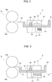
- FIG. 2 illustrates the roving-supply stop device 3 in the roving-supply allowable state. In the roving-supply allowable state, the stopper 30 is located away (retracted) from a nipping portion of the pair of back rollers 15.
- FIG. 3 illustrates the roving-supply stop device 3 in the roving-supply stop state.
- the stopper 30 is inserted in the nipping portion of the pair of back rollers 15.
- the stopper 30 and the lever 32 are arranged in the second position where the supply of the roving 9 to the drafting device 2 is stopped.
- switching the state of the roving-supply stop device 3 from the roving-supply allowable state to the roving-supply stop state means shifting the position of the stopper 30 and the lever 32 forming the roving-supply stop member from the first position illustrated in FIG. 2 to the second position illustrated in FIG. 3 .
- Switching the state of the roving-supply stop device 3 from the roving-supply stop state to the roving-supply allowable state means shifting the position of the stopper 30 and the lever 32 from the second position in FIG. 3 to the first position in FIG. 2 .
- the electromagnetic pin 38 of the stopper mechanism 33 is moved upward through a short energization of the electromagnetic coil. This causes the electromagnetic pin 38 to come off the recess 36 of the lever 32.
- the lever 32 is moved in the direction Y1 in FIG. 3 by the urging force of the urging member 34.
- the stopper 30 is moved to the second position illustrated in FIG. 3 , and is placed between the back top roller 15a and the back bottom roller 15b. This stops the supply of the roving 9 to the drafting device 2.
- the lever 32 is moved from its position in FIG. 3 in the direction Y2 by the operation of a return mechanism, which will be described later, against the urging force of the urging member 34.
- the recess 36 of the lever 32 reaches the position of the electromagnetic pin 38 of the stopper mechanism 33, the electromagnetic pin 38 is fitted in the recess 36 as illustrated in FIG. 2 .
- the stopper 30 is located away from the pair of back rollers 15, that is, the stopper 30 returns to the first position illustrated in FIG. 2 . This allows the supply of the roving 9 to the drafting device 2.
- the return mechanism is a mechanism for returning the roving-supply stop device 3 from the roving-supply stop state to the roving-supply allowable state automatically. "Automatically” described here means “without manual operation by an operator”. Returning the roving-supply stop device 3 means returning the stopper 30 and the lever 32, which form the roving-supply stop member, from the second position to the first position.
- the pot spinning machine 1 includes the return mechanism, which, in this embodiment, is a return mechanism 41.
- the return mechanism 41 includes a bar 42, a drive part 43, and a plurality of return members 44.
- the bar 42 is disposed movably in a longitudinal direction X of a base of the pot spinning machine 1.
- the drive part 43 moves the bar 42 in the base longitudinal direction X.
- Each of the return members 44 is disposed on the bar 42.
- the roving-supply stop devices 3 of the units of spinning are arranged in the base longitudinal direction X.
- the roving-supply stop devices 3 are located away from each other at regular intervals in the base longitudinal direction X.
- the bar 42 is a long member extending in the base longitudinal direction X, and corresponds to a moving member of the present disclosure.
- the roving-supply stop devices 3 are arranged in the base longitudinal direction X, and as illustrated in FIG. 2 , the bar 42 is disposed on each of the levers 32 of the arranged roving-supply stop devices 3 and interposed between the standing portion 35 of each lever 32 and the case 31.
- the bar 42 is disposed such that the bar 42 is reciprocable in the base longitudinal direction X.
- the bar 42 includes a plurality of connecting bars 42a, 42b wherein the connecting bar 42a is connected to the connecting bar 42b in the base longitudinal direction X.
- the connecting bar 42a and the connecting bar 42b are arranged adjacent to each other in the base longitudinal direction X, and connected to each other at a connection 45.
- FIG. 4 focuses on one of the connecting bars 42a and one of the connecting bars 42b; however, a predetermined number of unillustrated connecting bars are connected through the connections 45 on the left side of the connecting bar 42b illustrated in FIG. 4 .
- the configuration of the connection 45 will be described later.
- the drive part 43 includes an air cylinder 51 as a drive source and a bracket 52 that is reciprocated in the base longitudinal direction X by the air cylinder 51.
- the air cylinder 51 has a piston rod 53.
- the piston rod 53 is reciprocated in the base longitudinal direction X by the air cylinder 51.
- the bracket 52 is fixed to a leading end of the piston rod 53 with a pair of nuts 54.
- One end of the bar 42 is fixed to the bracket 52 with a screw or the like.
- the return member 44 is a member that moves together with the bar 42 when the bar 42 is moved by the drive part 43 in the base longitudinal direction X.
- the return mechanism 41 is a mechanism that engages the return member 44 with two or more of the roving-supply stop members in the second position when the drive part 43 of the return mechanism 41 moves the bar 42 and the return member 44 in the base longitudinal direction X and returns the two or more of the roving-supply stop members from the second position to the first position against the urging force of the urging member 34 through the engagement of the return member 44 with the two or more of the roving-supply stop members in the second position.
- the plurality of roving-supply stop devices 3 of the pot spinning machine 1 is returned simultaneously by as many return members 44 as the roving-supply stop devices 3. This increases the drive force required for the drive part 43 and increases the size of the air cylinder 51.
- one return member 44 is disposed for every N number (N is an integer greater than or equal to 2) of the roving-supply stop devices 3 when M number of the units of spinning are disposed. N is less than M. Specifically, one return member 44 is disposed for every four roving-supply stop devices 3.
- the return member 44 is arranged in a middle position between two adjacent roving-supply stop devices 3 in the base longitudinal direction X.
- the return member 44 is fixed to the bar 42 with a screw or the like.
- the return member 44 has an inclined portion 55 that is inclined to the base longitudinal direction X.
- the inclined portion 55 is engageable with the standing portion 35 of each lever 32 of the roving-supply stop devices 3 arranged in the base longitudinal direction X.
- the operation of the return mechanism 41 is performed by reciprocation of the bar 42 in the base longitudinal direction X by the air cylinder 51 of the drive part 43.
- the bar 42 is moved by the air cylinder 51 in a direction X1, so that the return member 44 moves in the direction X1 as the bar 42 moves.
- the inclined portion 55 of the return member 44 engages with the standing portion 35 of the lever 32 of the roving-supply stop device 3 in the roving-supply stop state, which causes the stopper 30 to be retracted together with the lever 32.
- FIG. 6 at (A)-(C) illustrates movement of the roving-supply stop devices 3 in that situation.
- the electromagnetic pin 38 is fitted in the recess 36 of the lever 32. Accordingly, the lever 32 is held in the first position against the urging force of the urging member 34.
- the return member 44 passes between the case 31 and the standing portion 35 as the bar 42 further moves.
- Such an operation of the return mechanism 41 enables the state of the roving-supply stop device 3 to return from the roving-supply stop state to the roving-supply allowable state. That is, the operation of the return mechanism 41 enables the stopper 30 and the lever 32 to return from the second position in FIG. 3 to the first position in FIG. 2 . All the roving-supply stop devices 3 arranged in the base longitudinal direction X might be in the roving-supply stop state.
- the return member 44 sequentially engages with the levers 32 of the roving-supply stop devices 3, which enables all the roving-supply stop devices 3 to return to the roving-supply allowable state.
- one return member 44 is disposed for every four roving-supply stop devices 3, so that one return member 44 enables the four roving-supply stop devices 3 to sequentially return from the roving-supply stop state to the roving-supply allowable state.
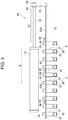
- FIG. 7 is a plane view with a fragmentary sectional view illustrating a connection when a bar spacing is decreased
- FIG. 8 illustrates a view of the connection of FIG. 7 when the connection is viewed in a direction R1.
- FIG. 9 is a plane view with a fragmentary sectional view illustrating the connection when the bar spacing is increased
- FIG. 10 is a view of the connection of FIG. 9 when the connection is viewed in a direction R2.
- a bar spacing change mechanism 60 is disposed at the connection 45.
- the bar spacing change mechanism 60 is a mechanism for changing a space between the connecting bars 42a, 42b depending on a moving direction in which the bar 42 moves when the bar 42 reciprocates along the base longitudinal direction X.
- the bar spacing change mechanism 60 is configured with the return member 44.
- the return member 44 connects the connecting bar 42a to the connecting bar 42b.
- the return member 44 has a wedge portion 61 that includes the inclined portion 55 and an attachment portion 62 that has a structure integral with the wedge portion 61.
- the wedge portion 61 protrudes in a direction perpendicular to a longitudinal direction of the bar 42 (the base longitudinal direction X).
- the attachment portion 62 is attached to the bar 42, so that the return member 44 connects the connecting bar 42a to the connecting bar 42b.
- the attachment portion 62 is attached to the bar 42 with two screws 63, 64.
- the screw 63 is screwed into a screw hole 46 formed in the connecting bar 42a
- the screw 64 is screwed into a screw hole 47 formed in the connecting bar 42b.
- the screw 64 is not illustrated in FIGS. 8 to 10 .
- the attachment portion 62 is fixed to the connecting bar 42a with the tightened screw 63.
- the attachment portion 62 has a long hole 65.
- the long hole 65 has a long axis in the longitudinal direction of the bar 42.
- a collar 66 having a cylindrical shape is inserted into the long hole 65.
- the collar 66 is fixed to the connecting bar 42b with the tightened screw 64.
- the collar 66 is movable in the long axis of the long hole 65.
- the bar spacing change mechanism 60 operates as follows when the bar 42 is reciprocated by the air cylinder 51 in the base longitudinal direction X.
- the direction X1 and the direction X2 respectively correspond to opposite directions along the base longitudinal direction X.
- the bar spacing change mechanism 60 that operates in such a way is disposed at the connection 45.
- This allows the space between the connecting bars 42a, 42b to increase from the space L1 to the space L2 when the bar 42 moves in the direction X1.
- This also allows the space between the connecting bars 42a, 42b to decrease from the space L2 to the space L1 when the bar 42 moves in the direction X2.
- the space between the connecting bars 42a, 42b is set to the space L1 before the bar 42 moves in the direction X1, or after the bar 42 moves in the direction X2, so that the return member 44 is accurately positioned between the adjacent levers 32 of the roving-supply stop devices 3 in the base longitudinal direction X.
- the roving-supply stop devices 3 are arranged at regular intervals in the base longitudinal direction X, and a space between two adjacent roving-supply stop devices 3 is referred to as a distance P1.
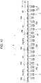
- the connecting bars 42a, 42b and connecting bars 42c (only three bars 42a, 42b, 42c are illustrated in FIG. 11 ), which cooperate to form the bar 42, are arranged and connected to each other.
- the return members 44 (44a to 44e) are disposed on the bar 42. Specifically, two return members 44a, 44b are fixed to the connecting bar 42a. In a similar way, two return members 44c, 44d are fixed to the connecting bar 42b, and two return members 44e (only one of them is illustrated in FIG. 11 ) are fixed to the return member 44c.
- the return member 44b connects the connecting bar 42a to the connecting bar 42b, and forms the above-described bar spacing change mechanism 60 (see FIGS. 7 to 10 ) at the connection 45 where the connecting bars 42a, 42b are connected to each other.
- the return member 44d connects the connecting bar 42b to the connecting bar 42c, and forms the above-described bar spacing change mechanism 60 at the connection 45 where the connecting bars 42b, 42c are connected to each other.
- a distance between the return member 44a and the return member 44b and a distance between the return member 44c and the return member 44d are each referred to as a distance P2, and each distance P2 is set to an integer multiple of the distance P1.
- one return member 44 is disposed for every four roving-supply stop devices 3, so that the distance P2 is set to four times the distance P1.
- a distance P3 between the return member 44b and the return member 44c is equal to the distance P2.
- the distance P3 between the return member 44d and the return member 44e is equal to the distance P2.
- FIG. 11 illustrates an arrangement before the bar 42 moves in the direction X1 or after the bar 42 moves in the direction X2.
- each of the distances P2, P3 between the adjacent return members 44 in the base longitudinal direction X is an integer multiple of the distance P1 between the adjacent roving-supply stop devices 3. Accordingly, each of the return members 44 (44a to 44e) is accurately positioned between the levers 32 of the roving-supply stop devices 3 adjacent in the base longitudinal direction X.
- FIG. 11 illustrates an arrangement before the bar 42 moves in the direction X1 or after the bar 42 moves in the direction X2.
- the bar spacing change mechanism 60 operates as described above first to move the connecting bar 42a located downstream of the bar moving direction X1, and then to move the connecting bar 42b and the connecting bar 42c sequentially. Accordingly, the space between the connecting bars 42a, 42b is increased from the space L1 to the space L2, and the space between the connecting bars 42b, 42c is increased from the space L1 to the space L2 as well.
- FIG. 11 illustrates an arrangement before the bar 42 moves in the direction X1 or after the bar 42 moves in the direction X2.
- a distance between the return member 44b and the return member 44c and a distance between the return member 44d and the return member 44e are each referred to as a distance P4 that is longer than the distance P3.
- the difference between the space L2 and the space L1 is defined as AL
- the difference between the distance P4 and the distance P3 is equivalent to ⁇ L.
- the distance between the return member 44b and the return member 44c is increased by an amount equivalent to one time the difference ⁇ L
- the distance between the return member 44b and the return member 44e is increased by an amount equivalent to two times the difference ⁇ L. That is, the increase in the bar spacing at each connection 45 increases the distance between the return members 44 fixed to the connecting bars 42a, 42b, or 42c in stages.
- a drive force required for the return members 44a, 44b, which move together with the connecting bar 42a, to return the roving-supply stop devices 3 becomes maximum at a timing T1
- a drive force required for the return members 44c, 44d, which move together with the connecting bar 42b, to return the roving-supply stop devices 3 becomes maximum at a timing T2.
- a drive force required for the return members 44e, which move together with the connecting bar 42c, to return the roving-supply stop devices 3 becomes maximum at a timing T3.
- the timings T1, T2, T3 are coincident if the whole bar 42 moves in the direction X1 with the bar spacing at each connection 45 set to the space L1. This increases the maximum value of the drive force required for the air cylinder 51 to move the bar 42 in the direction X1, thereby increasing variation of a drive load on the air cylinder 51.
- the timings T1, T2, T3 are different when the whole bar 42 moves in the direction X1 with the bar spacing at each connection 45 increased to the space L2 from the space L1. Specifically, the timing T2 becomes later than the timing T1, and the timing T3 becomes later than the timing T2. This disperses the drive load on the air cylinder 51 when the bar 42 moves in the direction X1. Further, this lowers the maximum value of the drive force required for the air cylinder 51. As a result, this enables the air cylinder 51 as a drive source of the drive part 43 to be downsized.
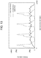
- FIG. 13 is a graph illustrating a relationship between a bar moving distance and a tensile load applied on the bar when the return mechanism returns the roving-supply stop device, which was found by an experiment.
- a solid line shows a variation of the tensile load when a bar spacing is changeable by the bar spacing change mechanism 60
- a dashed line shows a variation of the tensile load when the bar spacing is constant.
- the connecting bars 42a, 42b, 42c are integrally formed or the connecting bars 42a, 42b, 42c are connected to each other with screws or the like such that the connecting bars 42a, 42b, 42c move integrally, regardless of the moving direction of the bar 42 along the base longitudinal direction X.
- the bar 42 When the bar 42 with constant bar spacing is moved in the direction X1 to cause the return member 44 to sequentially return the roving-supply stop devices 3, the bar 42 receives a peak value Pa of the tensile load every time the bar 42 is moved at a predetermined amount. This is caused by coincidence among the timings T1, T2, T3.
- the bar 42 has a changeable bar spacing
- the bar 42 receives a peak value Pb of the tensile load that is flattened (dispersed) because the timings T1, T2, T3 are different.
- the peak value Pb of the tensile load on the bar 42 with a changeable bar spacing is considerably lower than the peak value Pa of the tensile load on the bar 42 with a constant bar spacing. This means that providing the bar spacing change mechanism 60 considerably lowers the maximum value of the drive force required for the air cylinder 51.
- the operation of the return mechanism 41 returns the roving-supply stop member (the stopper 30, the lever 32) from the second position to the first position, if the roving-supply stop member (the stopper 30, the lever 32) of the roving-supply stop device 3 of any unit of spinning is shifted from the first position to the second position during spinning of the roving 9.
- This enables automatic return of the roving-supply stop device 3 without manual operation by an operator.
- the return member 44 has the inclined portion 55, and is configured to engage the inclined portion 55 with the standing portion 35 of the lever 32 in the second position and return the stopper 30 and the lever 32 to the first position through the engagement of the inclined portion 55 with the standing portion 35 of the lever 32 in the second position.
- the return member 44 is disposed for every four roving-supply stop devices 3. This configuration reduces the number of the roving-supply stop devices 3 coincidently returned by one return member 44. Accordingly, this configuration reduces the drive force required for the drive part 43, thereby enabling the air cylinder 51 to be downsized.
- the bar 42 that is reciprocable in the base longitudinal direction X serves as the moving member. This low cost configuration enables automatic return of the roving-supply stop device 3.
- the bar spacing change mechanism 60 is disposed at each of the connections 45 that connects the connecting bars 42a, 42b, 42c adjacent to each other in the base longitudinal direction X. This configuration lowers the maximum value of the drive force required for the drive part 43, thereby enabling the drive part 43 to be downsized.
- the pot spinning machine according to the second embodiment of the present disclosure includes a return mechanism having a different configuration from that of the return mechanism 41 according to the first embodiment. The following will describe the configuration in detail.
- FIG. 14 is a schematic view illustrating the configuration of a return mechanism of the pot spinning machine according to the second embodiment of the present disclosure.
- a return mechanism 71 includes a wire 72 that serves as the moving member, a pair of pulleys 73a, 73b that supports the wire 72 with the wire 72 elongated in the base longitudinal direction X, a motor 74 that rotates the pulley 73a, and two return members 75 that are disposed on the wire 72.
- the wire 72 is supported in a loop shape by the pair of pulleys 73a, 73b.
- the wire 72 is interposed between the standing portion 35 of each lever 32 and the case 31 when the roving-supply stop devices 3 are arranged in the base longitudinal direction X.
- the pulley 73a is a drive pulley
- the pulley 73b is a driven pulley.
- the pulley 73a is rotated by the motor 74.
- the pulley 73b is rotated by the movement of the wire 72.
- Each return member 75 has an inclined portion 76.
- the return members 75 are fixed to the wire 72 at different positions in a longitudinal direction of the looped wire 72. Accordingly, each return member 75 is moved together with the wire 72 when the wire 72 is moved by the rotation of the pulley 73a rotated by the motor 74.
- the pair of pulleys 73a, 73b and the motor 74 cooperate to form the drive part that moves the wire 72, which serves as the moving member, in the base longitudinal direction X.
- the pulley 73a is rotated by the motor 74 in a counterclockwise direction in FIG. 14 to return each roving-supply stop device 3 from the roving-supply stop state to the roving-supply allowable state.
- One of the return members 75 (lower one in FIG. 14 ) located between the pulleys 73a, 73b moves from the pulley 73b side toward the pulley 73a side along the direction X1.
- the inclined portion 76 of the return member 75 moving in the direction X1 engages with the standing portion 35 of the lever 32 of the roving-supply stop device 3, so that the lever 32 moves in the direction Y2.
- each of the roving-supply stop devices 3 arranged in the base longitudinal direction X to be returned sequentially from the roving-supply stop state to the roving-supply allowable state. Accordingly, this configuration provides the same effect as the effect of the first embodiment.
- the wire 72 serves as the moving member. This enables automatic return of the roving-supply stop device 3 with a low-cost configuration.
- the return member 75 does not necessarily need the inclined portion 76.
- the return member of the present disclosure may be provided by a roller 77 disposed on the wire 72.
- the roller 77 corresponds to a first roller of the present disclosure that is engageable with the roving-supply stop member in the second position.
- the roller 77 is rotatably disposed.
- the lever 32 is also returned from the second position to the first position through the engagement of the roller 77 with the standing portion 35 of the lever 32 in the second position.
- the roller 77 engages with the standing portion 35 of the lever 32 while rotating, so that rolling resistance is generated at the engaging part between the roller 77 and the lever 32, instead of sliding resistance. This reduces the drive force required for returning the roving-supply stop device 3.
- two rollers 77a, 77b serving as the first roller may be disposed on the wire 72 at one position.
- the roller 77a is rotated by the standing portion 35 engaging with the roller 77a, and the other roller 77b is rotated by the case 31 engaging with the roller 77b. This lowers the drive force required for returning the roving-supply stop device 3.
- each roving-supply stop device 3 may have a roller 78.
- the roller 78 is disposed on a portion of the roving-supply stop device 3, which in this embodiment, is the standing portion 35, with which the inclined portion 76 of the return member 75 engages.
- the roller 78 corresponds to a second roller of the present disclosure.
- the inclined portion 76 of the return member 75 engages with the roller 78 when the return member 75 engages with the roving-supply stop device 3, which rotates the roller 78. This lowers the drive force required for returning the roving-supply stop device 3.
- the wire 72 serves as the moving member, but the bar 42 may serve as the moving member, instead of the wire 72.
- a bar spacing change mechanism disposed at the connection 45 between the connecting bar 42a and the connecting bar 42b has a different configuration from that of the first embodiment. The following will describe it in detail.
- FIG. 18A is a schematic plane view illustrating the configuration of a bar spacing change mechanism of the pot spinning machine according to the third embodiment of the present disclosure.
- FIG. 18B is a schematic front view of the bar spacing change mechanism of FIG. 18A .
- a bar spacing change mechanism 81 includes a flat spring 82 that is bent into an approximately triangular shape, a screw 83a for fixing one end of the flat spring 82 to the connecting bar 42a, and a screw 83b for fixing the other end of the flat spring 82 to the connecting bar 42b.
- the connecting bars 42a, 42b are urged by an urging force of the flat spring 82 such that the connecting bars 42a, 42b approach each other along the base longitudinal direction X.
- the space between the connecting bars 42a, 42b at the connection 45 changes depending on the moving direction in which the bar 42 moves when the bar 42 reciprocates along the base longitudinal direction X. This lowers the maximum value of the drive force required for returning the roving-supply stop device 3, as in the first embodiment.
- the configuration of the bar spacing change mechanism is not limited to the above embodiments, but may be modified. Specifically, the configuration of a bar spacing change mechanism 84 as illustrated in FIGS. 19A to 19C may be adopted, for example.
- the connecting bar 42a has a hook portion 85a and a cutout 86a
- the connecting bar 42b has a hook portion 85b and a cutout 86b.
- the hook portion 85a of the connecting bar 42a is disposed in the cutout 86b of the connecting bar 42b
- the hook portion 85b of the connecting bar 42b is disposed in the cutout 86a of the connecting bar 42a. This allows the connecting bars 42a, 42b to be connected to each other in the base longitudinal direction X as illustrated in FIG. 1(B) .
- the connecting bar 42a when the connecting bar 42a is moved in the direction X1 from a state illustrated in FIG. 19B , first, the hook portion 85a of the connecting bar 42a moves in the cutout 86b of the connecting bar 42b in the direction X1, and then the hook portion 85a contacts the hook portion 85b as illustrated in FIG. 19C . Then, the connecting bar 42b is pulled by the connecting bar 42a with the hook portion 85a catching the hook portion 85b, so that the connecting bar 42b moves in the direction X1. Accordingly, the whole bar 42 moves in the direction X1 with the space between the connecting bars 42a, 42b increased to a space L4.
- the connecting bar 42a when the connecting bar 42a is moved in the direction X2 from a state illustrated in FIG. 19C , first, the hook portion 85a of the connecting bar 42a moves in the cutout 86b of the connecting bar 42b in the direction X2, and then the hook portion 85a contacts one end of the cutout 86b or the hook portion 85b contacts the other end of the cutout 86a as illustrated in FIG. 19B . Then, the connecting bar 42b is pushed by the connecting bar 42a with the hook portion 85a contacting the cutout 86b or with the hook portion 85b contacting the cutout 86a, so that the connecting bar 42b moves in the direction X2. Accordingly, the whole bar 42 moves in the direction X2 with the space between the connecting bars 42a, 42b decreased to a space L3.
- the fourth embodiment of the present disclosure has a feature of a method for controlling a spinning machine.
- This controlling method is realized by use of the return mechanism of the pot spinning machine according to the first, second and third embodiments of the present disclosure.
- the method for controlling the pot spinning machine according to the present disclosure is applicable not only to the pot spinning machine having the above-described return mechanism according to the embodiments of the present disclosure, but broadly applicable to a pot spinning machine having a mechanism for returning the roving-supply stop device 3.
- the roving-supply stop device 3 is activated when a yarn breakage occurs, so that the stopper 30 is placed between the back top roller 15a and the back bottom roller 15b to stop the supply of the roving 9 to the drafting device 2.
- the pair of middle rollers 16 and the pair of front rollers 17 keep rotating. This causes the roving 9 to be cut at a position proximal to the pair of middle rollers 16 in a unit of spinning in which a yarn breakage has occurred. This reduces the length of the roving 9 to be sucked by the pneumatic device.
- a position at which the roving 9 is cut differs between a unit of spinning in which the yarn breakage has occurred during spinning (hereinafter called “a unit of spinning with yarn breakage”) and a unit of spinning in which the yarn breakage has not occurred during spinning (hereinafter called “a unit of spinning without yarn breakage”).
- a unit of spinning with yarn breakage a unit of spinning in which the yarn breakage has occurred during spinning
- a unit of spinning without yarn breakage a unit of spinning without yarn breakage
- the roving 9 is cut at the position proximal to the pair of front rollers 17 because the rotation of the pair of back rollers 15 and the rotation of the pair of middle rollers 16 are stopped. Accordingly, when the pair of back rollers 15 and the pair of middle rollers 16 restart rotating for next spinning step in every unit of spinning including the unit of spinning with yarn breakage and the unit of spinning without yarn breakage, the roving 9 in the unit of spinning with yarn breakage moves from the position proximal to the pair of middle rollers 16, and the roving 9 in the unit of spinning without yarn breakage moves from the position proximal to the pair of front rollers 17.
- a pot spinning machine is controlled by the following method.
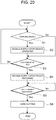
- FIG. 20 is a flowchart illustrating a method for controlling a spinning machine according to the fourth embodiment of the present disclosure.
- the method for controlling a spinning machine illustrated in FIG. 20 is performed under control of a controller, which is not illustrated, and is applied to the spinning step where the yarn 20 supplied from the drafting device 2 is spun into the pot 5.
- the controller checks whether the yarn breakage sensor 7 in any unit of spinning has detected the occurrence of yarn breakage during spinning (step S1). If the occurrence of yarn breakage is detected by the yarn breakage sensor 7, the controller identifies the unit of spinning with yarn breakage based on a yarn breakage detection signal from the yarn breakage sensor 7, and activates the roving-supply stop device 3 disposed in the identified unit of spinning with yarn breakage (step S2).
- step S1 the method transitions from step S1 to step S3.
- step S3 determines whether the formation of the cake 24 has ended.
- the formation of the cake 24 ends at a stage where the predetermined amount of the yarn 20 is deposited on the inside wall 5b of the pot 5.
- the method returns to step S1 when the formation of the cake 24 has not ended, or transitions to step S4 when the formation of the cake 24 has ended.
- the controller then all returns the roving-supply stop device(s) 3, which has been activated in step S2, into the roving-supply allowable state (step S4).
- the bar 42 of the return mechanism 41 is moved by the air cylinder 51 in the direction X1. Accordingly, the roving-supply stop device 3 in every unit of spinning including the unit of spinning with yarn breakage and the unit of spinning without yarn breakage is put into the roving-supply allowable state.
- stopper 30 is retracted from the pair of back rollers 15 when the roving-supply stop device 3 in the unit of spinning with yarn breakage is returned to the roving-supply allowable state, so that the supply of the roving 9 to the drafting device 2 restarts.
- the controller determines whether a predetermined time has passed since the roving-supply stop device 3 is returned in step S4 (step S5).
- the predetermined time is set according to time required for a leading end of the roving 9, which has been cut at the position proximal to the pair of middle rollers 16 by the roving-supply stop device 3 activated in step S2, to reach the pair of front rollers 17 by the restart of the supply of the roving 9 in step S4.
- the predetermined time can be experimentally calculated.
- step S6 when the controller determines that the predetermined time has passed, the rotation of the pair of back rollers 15 and the rotation of the pair of middle rollers 16 are stopped simultaneously in all the units of spinning for yarn cutting (step S6). Yarn spinning ends by the yarn cutting.
- yarn cutting is performed after the predetermined time has passed, and the roving-supply stop device 3 is returned into the roving-supply allowable state before the predetermined time starts.
- the pot spinning machine 1 returns the roving-supply stop device 3 from the second state to the first state before spinning ends when the roving-supply stop device 3 is switched from the first state to the second state during the spinning.
- the leading end of the roving 9 is located at a position proximal to the pair of front rollers 17 in each of all units of spinning at the end of spinning step.
- controlling the spinning machine enables the pair of back rollers 15 and the pair of middle rollers 16 to restart rotating in the next spinning step in a state where the leading end of the roving 9 is arranged at a position proximal to the pair of front rollers 17 in every unit of spinning, that is, in a state where all the units of spinning are ready for spinning.
- This decreases the time it takes for the roving 9 fed from the drafting device 2 to reach the yarn suction pipe 22 in every unit of spinning. This therefore decreases air suction time by the yarn suction pipe 22, thereby reducing energy waste.
- this enables the leading end of the roving 9 to be fed from the drafting device 2 from the same position in all the units of spinning, thereby allowing the yarn 20 to be rewound on the bobbin 25 at the same position in all the units of spinning in the rewinding step after the spinning step. This increases the yield rate of yarn in the winder step after spinning.
- one return member 44 is disposed for every four roving-supply stop devices 3 in the return mechanism 41; however, the ratio of the number of the return members 44 to the number of the roving-supply stop devices 3 is not limited to the above specific example, but may be modified.
- a pot spinning machine is cited in the above-described embodiments, but the present disclosure is not limited to a pot spinning machine, but may be applicable to any spinning machines, such as a ring spinning machine.
- a spinning machine (1) includes a roving-supply stop device (3) that includes a roving-supply stop member (30, 32) shifted between a first position for allowing the supply of a roving (9) to a drafting device (2) and a second position for stopping the supply of the roving (9) to the drafting device (2), and a holding member (38) for holding the roving-supply stop member (30, 32) in the first position against an urging force of an urging member (34).
- the spinning machine (1) further includes a return mechanism (41, 71) including a moving member (42, 72), a drive part (43, 73a, 73b, 74), and a return member (44, 44a-44e, 75).
- the return mechanism (41, 71) engages the return member (44, 44a-44e, 75) with two or more roving-supply stop members (30, 32) in the second position when the drive part (43, 73a, 73b, 74) moves the moving member (42, 72) together with the return member (44, 44a-44e, 75) in a base longitudinal direction (X), and returns the two or more roving-supply stop members (30, 32) from the second position to the first position through the engagement of the return member (44, 44a-44e, 75).
Landscapes
- Engineering & Computer Science (AREA)
- Mechanical Engineering (AREA)
- Textile Engineering (AREA)
- Spinning Or Twisting Of Yarns (AREA)
Abstract
Description
- The present disclosure relates to a spinning machine and a method for controlling a spinning machine.
- Some spinning machines including a drafting device for drawing out a roving include a roving-supply stop device for stopping supply of the roving to the drafting device. Japanese Patent Application Publication No.
57-133224 - In a known spinning machine, however, when the supply of the roving is stopped by the roving-supply stop device, the operator manually returns the roving-supply stop device into a state of the roving-supply stop device before the roving-supply stop device is activated. Accordingly, the supply of the roving is not allowed to restart automatically, which is an obstacle in automation of the spinning machine. This obstacle may be removed if the slider of the roving-supply stop device is directly driven by a solenoid device, but this requires the solenoid device to have capacity large enough to resist the urging force of the compression spring. Further, the single spinning machine includes a plurality of units of spinning, and each of the units of spinning includes a roving-supply stop device. Accordingly, if the slider of each roving-supply stop device is individually driven by a high-capacity solenoid device, it leads to upsizing of the roving-supply stop device, thereby increasing the cost of the roving-supply stop device.
- The present disclosure, which has been made in light of the above-mentioned problem, is directed to providing a spinning machine and a method for controlling the spinning machine that enables automatic return of a roving-supply stop device and allows downsizing of the roving-supply stop device.
- In accordance with an aspect of the present disclosure, there is provided a spinning machine that includes a plurality of units of spinning each including a drafting device for drawing out a roving and a roving-supply stop device for stopping supply of the roving to the drafting device. The roving-supply stop devices of the units of spinning are arranged in a longitudinal direction of a base of the spinning machine and each include a roving-supply stop member, an urging member, and a holding member. The roving-supply stop member is shifted between a first position for allowing the supply of the roving to the drafting device and a second position for stopping the supply of the roving to the drafting device. The urging member urges the roving-supply stop member to the second position. The holding member holds the roving-supply stop member in the first position against an urging force of the urging member. The spinning machine further includes a return mechanism that includes a moving member, a drive part, and a return member. The moving member extends in the base longitudinal direction and is disposed movably in the base longitudinal direction. The drive part moves the moving member in the base longitudinal direction. The return member is disposed on the moving member and moved together with the moving member when the drive part moves the moving member in the base longitudinal direction. The return mechanism engages the return member with two or more of the roving-supply stop members in the second position when the drive part moves the moving member together with the return member in the base longitudinal direction, and returns the two or more of the roving-supply stop members from the second position to the first position against the urging force of the urging member through the engagement of the return member with the two or more of the roving-supply stop members in the second position.
- In accordance with another aspect of the present disclosure, there is provided a method for controlling a spinning machine. The spinning machine includes a plurality of units of spinning each including a drafting device for drawing out a roving and a roving-supply stop device for stopping supply of the roving to the drafting device. The roving-supply stop devices of the units of spinning are arranged in a longitudinal direction of a base of the spinning machine. The roving-supply stop device is switched between a first state for allowing the supply of the roving to the drafting device and a second state for stopping the supply of the roving to the drafting device. The method for controlling the spinning machine includes spinning a yarn supplied from the drafting device. The method for controlling the spinning machine further includes returning the roving-supply stop device from the second state to the first state before spinning ends when the roving-supply stop device is switched from the first state to the second state during the spinning.
- Other aspects and advantages of the disclosure will become apparent from the following description, taken in conjunction with the accompanying drawings, illustrating by way of example the principles of the disclosure.
- The disclosure, together with objects and advantages thereof, may best be understood by reference to the following description of the embodiments together with the accompanying drawings in which:
-
FIG. 1 is a schematic view illustrating an exemplary configuration of a pot spinning machine according to a first embodiment of the present disclosure; -
FIG. 2 is a schematic sectional side view of a roving-supply stop device before the roving-supply stop is activated; -
FIG. 3 is a schematic sectional side view of the roving-supply stop device after the roving-supply stop is activated; -
FIG. 4 is a schematic plane view illustrating a configuration of a return mechanism according to the first embodiment of the present disclosure; -
FIG. 5 is a schematic plane view illustrating an operation of the return mechanism according to the first embodiment of the present disclosure; -
FIG. 6 at (A)-(C) is views illustrating a movement of the roving-supply stop device moved by the return mechanism; -
FIG. 7 is a plane view with a fragmentary sectional view illustrating a connection when a bar spacing is decreased; -
FIG. 8 is a view of the connection ofFIG. 7 when the connection is viewed in a direction R1; -
FIG. 9 is a plane view with a fragmentary sectional view illustrating the connection when the bar spacing is increased; -
FIG. 10 is a view of the connection ofFIG. 9 when the connection is viewed in a direction R2; -
FIG. 11 is a schematic plane view illustrating a distance between return members when a space between connecting bars is decreased; -
FIG. 12 is a schematic plane view illustrating the distance between the return members when the space between the connecting bars is increased; -
FIG. 13 is a graph illustrating a relationship between a bar moving distance and a tensile load applied on the bar; -
FIG. 14 is a schematic view illustrating the configuration of a return mechanism of a pot spinning machine according to a second embodiment of the present disclosure; -
FIG. 15 is a schematic view of a first modification of a return mechanism; -
FIG. 16 is a schematic view of a second modification of a return mechanism; -
FIG. 17 is a schematic view of a third modification of a return mechanism; -
FIG. 18A is a schematic plane view illustrating the configuration of a bar spacing change mechanism of a pot spinning machine according to a third embodiment of the present disclosure, andFIG. 18B is a schematic front view ofFIG. 18A ; -
FIGS. 19A-19C are schematic views of a modification of a bar spacing change mechanism; and -
FIG. 20 is a flowchart illustrating a method for controlling a spinning machine according to a fourth embodiment of the present disclosure. - The following will describe embodiments of the present disclosure in detail with reference to the accompanying drawings.
- The following will describe the configuration of a pot spinning machine according to a first embodiment of the present disclosure.
-
FIG. 1 is a schematic view illustrating an exemplary configuration of the pot spinning machine according to the first embodiment of the present disclosure. - As illustrated in
FIG. 1 , apot spinning machine 1 includes a drafting device 2, a roving-supply stop device 3, ayarn introduction pipe 4, apot 5, abobbin support part 6, and ayarn breakage sensor 7. These elements cooperate to form a unit of spinning. Thepot spinning machine 1 includes a plurality of units of spinning with a common configuration, and the following will focus on the configuration of a single unit of spinning. - The drafting device 2 is a device for drawing out a roving 9 serving as a yarn material to a predetermined thickness. The drafting device 2 includes multiple pairs of rollers that include a pair of
back rollers 15, a pair ofmiddle rollers 16, and a pair offront rollers 17. The multiple pairs of rollers are arranged from upstream to downstream of a roving delivery direction in the following order; the pair ofback rollers 15, the pair ofmiddle rollers 16, and the pair offront rollers 17. - The pair of
back rollers 15 includes a backtop roller 15a and a backbottom roller 15b. The backtop roller 15a and the backbottom roller 15b are in contact with each other under a predetermined pressure. The backtop roller 15a is a driven roller, and the backbottom roller 15b is a drive roller. Accordingly, the backtop roller 15a is rotated by rotation of the backbottom roller 15b. - The pair of
middle rollers 16 includes a middle top roller 16a and amiddle bottom roller 16b. The middle top roller 16a and themiddle bottom roller 16b are in contact with each other under a predetermined pressure. The middle top roller 16a is a driven roller, and themiddle bottom roller 16b is a drive roller. Accordingly, the middle top roller 16a is rotated by rotation of themiddle bottom roller 16b. A pair ofaprons 19 is wound around the pair ofmiddle rollers 16. The pair ofaprons 19 includes a top apron 19a and abottom apron 19b. The top apron 19a is wound over the middle top roller 16a, and thebottom apron 19b is wound over themiddle bottom roller 16b. - The pair of
front rollers 17 includes a fronttop roller 17a and afront bottom roller 17b. The fronttop roller 17a and thefront bottom roller 17b are in contact with each other under a predetermined pressure. The fronttop roller 17a is a driven roller, and thefront bottom roller 17b is a drive roller. Accordingly, the fronttop roller 17a is rotated by rotation of thefront bottom roller 17b. - The pairs of
rollers rollers middle rollers 16 is greater than the rpm of the pair ofback rollers 15, and the rpm of the pair offront rollers 17 is greater than the rpm of the pair ofmiddle rollers 16. Accordingly, the rpm of the pairs ofrollers rollers rollers yarn 20 that has been drawn out by the drafting device 2 to a predetermined thickness is supplied from the drafting device 2 to theyarn introduction pipe 4 through ayarn suction pipe 22. - The roving-
supply stop device 3 is a device for stopping supply of the roving 9 to the drafting device 2. The roving-supply stop device 3 includes astopper 30. Thestopper 30 is disposed so as to move toward or away from the pair ofback rollers 15 of the drafting device 2. The roving-supply stop device 3 places thestopper 30 between the backtop roller 15a and the backbottom roller 15b of the pair ofback rollers 15 to stop the supply of the roving 9 to the drafting device 2. - When the roving-
supply stop device 3 is activated, thestopper 30 is moved toward a nipping position of the pair ofback rollers 15. Thestopper 30 is placed between the backtop roller 15a and the backbottom roller 15b. Thestopper 30 blocks the transmission of the rotation of the backbottom roller 15b to the backtop roller 15a. Further, the roving 9 is caught between the backtop roller 15a and thestopper 30. This stops the supply of the roving 9 to the drafting device 2. - The
yarn introduction pipe 4 introduces theyarn 20, which has been supplied from the drafting device 2 through theyarn suction pipe 22, to thepot 5. Theyarn 20 drawn out by the drafting device 2 is introduced into theyarn suction pipe 22, for example, by swirling air flow, and theyarn 20 is further introduced into theyarn introduction pipe 4 through theyarn suction pipe 22. Theyarn introduction pipe 4 has a long thin tube-like shape. Theyarn introduction pipe 4 is disposed downstream from the drafting device 2, and is coaxial with thepot 5. A lower portion of theyarn introduction pipe 4 is disposed in thepot 5. Theyarn introduction pipe 4 has ayarn outlet 4a at a bottom end of theyarn introduction pipe 4. Theyarn 20 introduced into theyarn introduction pipe 4 is discharged from theyarn outlet 4a of theyarn introduction pipe 4. - The
pot 5 is used for formation of acake 24 and rewinding of theyarn 20. Thepot 5 has a cylindrical shape. Thepot 5 is rotatable about a central axis K of thepot 5. The central axis K of thepot 5 is disposed parallel to a vertical direction. Accordingly, one side of thepot 5 is an upper side, and the other side of thepot 5 is a lower side in the central axis K direction. Thepot 5 has anopening 5a at a bottom end of thepot 5. Thecake 24 is a deposit of theyarn 20 that is formed on aninside wall 5b of thepot 5. - The
bobbin support part 6 supports abobbin 25. Thebobbin support part 6 is movable in an up-down direction. Thebobbin support part 6 includes abobbin seat 26 and abobbin attachment portion 27. Thebobbin seat 26 has a plate-like shape. Thebobbin attachment portion 27 is fixed to thebobbin seat 26. - The
yarn breakage sensor 7 is a sensor for detecting the occurrence of a yarn breakage. Theyarn breakage sensor 7 is disposed downstream from the drafting device 2. - Next, the following will describe the basic operation performed by the
pot spinning machine 1 that has the above-described configuration. - Steps performed by the
pot spinning machine 1 include at least a spinning step in which theyarn 20 supplied from the drafting device 2 is spun into thepot 5, and a rewinding step in which theyarn 20 spun into thepot 5 is rewound onto thebobbin 25. The following will describe the operation of thepot spinning machine 1 at the spinning step and the rewinding step. The spinning step and the rewinding step are performed while thepot 5 is rotated at a predetermined rotational speed. - At the spinning step, the pair of
back rollers 15, the pair ofmiddle rollers 16, and the pair offront rollers 17 are each rotated at a predetermined rotational speed. The rotation of each pair ofrollers middle rollers 16 is rotated faster than the pair ofback rollers 15, and the pair offront rollers 17 is rotated faster than the pair ofmiddle rollers 16. In this way, the roving 9 is drawn out to a predetermined thickness by a difference in rotational speed among the pairs ofrollers - The
yarn 20 that has been drawn out by the drafting device 2 is introduced from the drafting device 2 into theyarn introduction pipe 4 through theyarn suction pipe 22. Theyarn 20 that has been introduced into theyarn introduction pipe 4 is spun from theyarn outlet 4a of theyarn introduction pipe 4 and onto theinside wall 5b of thepot 5 by a centrifugal force generated by the rotation of thepot 5. Theyarn 20 is twisted by the rotation of thepot 5. - At the spinning step, the
yarn introduction pipe 4 reciprocates in the up-down direction at a predetermined cycle while shifting its position downward stepwise. Accordingly, a predetermined amount of theyarn 20 is deposited on theinside wall 5b of thepot 5. As a result, thecake 24 is formed on theinside wall 5b of thepot 5. After thecake 24 is formed, yarn cutting is performed. Specifically, the rotation of the pair ofback rollers 15 and the rotation of the pair ofmiddle rollers 16 are both stopped with the pair offront rollers 17 rotating. This makes theyarn 20 forcibly cut at a position proximal to the pair offront rollers 17. The spinning step then ends. - At the rewinding step, the
bobbin seat 26 moves upward with thepot 5 rotating at the predetermined rotational speed. Thebobbin 25 moves upward together with thebobbin seat 26, and theyarn introduction pipe 4 moves upward so as not to contact thebobbin 25. Thebobbin 25 enters thepot 5 through theopening 5a of thepot 5. Accordingly, thebobbin 25 is inserted into thepot 5. - Next, a feeler (not illustrated) contacts the
inside wall 5b of thepot 5 to remove theyarn 20 wound on a bottom end side of thecake 24 from theinside wall 5b of thepot 5. Theyarn 20 removed from theinside wall 5b of thepot 5 is wound onto thebobbin 25, which starts the yarn rewinding onto thebobbin 25. - After the
whole yarn 20 of thecake 24 is rewound onto thebobbin 25, thebobbin seat 26 moves downward. Consequently, thebobbin 25 onto which theyarn 20 is rewound, i.e., thefull bobbin 25, is removed from thepot 5. The rewinding step then ends. - At the above-described spinning step, a yarn breakage may occur during spinning for any reason. The occurrence of the yarn breakage is detected by the
yarn breakage sensor 7. The following will describe the difference between "yarn cutting" and "yarn breakage". The yarn cutting is intentionally performed in a state where a predetermined amount of theyarn 20 is wound onto theinside wall 5b of thepot 5, that is, after the formation of thecake 24 ends. In contrast, the yarn breakage is a phenomenon that theyarn 20 is broken for any reason before the predetermined amount of theyarn 20 is wound onto theinside wall 5b of thepot 5, that is, during the formation of thecake 24. - If the yarn breakage occurs during the spinning, the
yarn 20 fed from the drafting device 2 is collected by a yarn collecting device (not illustrated). The yarn collecting device is called a pneumatic device, and includes a nozzle for collecting yarn. The yarn collecting device sucks in theyarn 20 with air via the nozzle to collect theyarn 20. At that time, the roving-supply stop device 3 and theyarn breakage sensor 7 are used to suppress theyarn 20 from being unnecessarily collected by the yarn collecting device. Specifically, if a yarn breakage occurs during spinning, theyarn breakage sensor 7 outputs a yarn breakage detection signal, and the signal activates the roving-supply stop device 3 in the unit of spinning in which the yarn breakage has occurred. The following will describe the configuration and the operation of the roving-supply stop device 3. - As illustrated in
FIG. 2 , the roving-supply stop device 3 includes acase 31, alever 32, astopper mechanism 33, and an urgingmember 34 other than the above-describedstopper 30. - The
stopper mechanism 33 and the urgingmember 34 are accommodated in thecase 31. Thelever 32 is disposed movably in a direction Y to allow thestopper 30 to move toward or away from the pair ofback rollers 15. Thestopper 30 is fixed to a distal end of thelever 32. Thelever 32 has arecess 36. Therecess 36 is opened upward. Thelever 32 has apressure receiving portion 37. Thepressure receiving portion 37 protrudes downward. Thepressure receiving portion 37 may be formed integrally with thelever 32, or may be fixed to thelever 32 with a screw, an adhesive, or the like. Thelever 32 has a standingportion 35 formed integrally with a proximal end of thelever 32. Thelever 32 having the standingportion 35 and thestopper 30 attached to thelever 32 cooperate to form a roving-supply stop member. - The
stopper mechanism 33 has anelectromagnetic pin 38. Theelectromagnetic pin 38 corresponds to a holding member for holding the roving-supply stop member, which includes thestopper 30 and thelever 32, in a first position (described later), against the urging force of the urgingmember 34. Theelectromagnetic pin 38 is fitted in therecess 36 of thelever 32 to regulate the movement of thelever 32 against the urging force of the urgingmember 34. Theelectromagnetic pin 38 is disposed movably in the up-down direction. Theelectromagnetic pin 38 is moved upward by a magnetic force generated through energization of a magnet coil (not illustrated). When the magnetic coil is not energized, theelectromagnetic pin 38 receives a downward force under the weight of theelectromagnetic pin 38 or from a spring (not illustrated). - The urging
member 34 is a member for urging the roving-supply stop member, which includes thestopper 30 and thelever 32, toward a second position (which will be described later). The urgingmember 34 urges thelever 32 in a direction in which thestopper 30 approaches the pair of back rollers 15 (the leftward direction ofFIG. 2 ). The urgingmember 34 is provided by a compression coil spring in this embodiment. The urgingmember 34 applies the urging force (pressure of spring) to thepressure receiving portion 37 of thelever 32. The urgingmember 34 is not limited to a compression coil spring, but may be an extension coil spring or an elastic member (for example, rubber) other than the spring. Alternatively, thelever 32 may be urged by a pressure of fluid, such as air. - The roving-
supply stop device 3 that has the above-described configuration is switched between a first state for allowing the supply of the roving 9 to the drafting device 2 (hereinafter called a roving-supply allowable state) and a second state for stopping the supply of the roving 9 to the drafting device 2 (hereinafter called a roving-supply stop state). Switching of the state of the roving-supply stop device 3 is performed by activating the roving-supply stop device 3 or by returning the roving-supply stop device 3. In the description, activating the roving-supply stop device 3 means switching the state of the roving-supply stop device 3 from the roving-supply allowable state to the roving-supply stop state, and returning the roving-supply stop device 3 means switching the state of the roving-supply stop device 3 from the roving-supply stop state to the roving-supply allowable state.FIG. 2 illustrates the roving-supply stop device 3 in the roving-supply allowable state. In the roving-supply allowable state, thestopper 30 is located away (retracted) from a nipping portion of the pair ofback rollers 15. In the roving-supply allowable state, thestopper 30 and thelever 32 are arranged in the first position where the supply of the roving 9 to the drafting device 2 is allowed.FIG. 3 illustrates the roving-supply stop device 3 in the roving-supply stop state. In the roving-supply stop state, thestopper 30 is inserted in the nipping portion of the pair ofback rollers 15. In the roving-supply stop state, thestopper 30 and thelever 32 are arranged in the second position where the supply of the roving 9 to the drafting device 2 is stopped. In the description, switching the state of the roving-supply stop device 3 from the roving-supply allowable state to the roving-supply stop state means shifting the position of thestopper 30 and thelever 32 forming the roving-supply stop member from the first position illustrated inFIG. 2 to the second position illustrated inFIG. 3 . Switching the state of the roving-supply stop device 3 from the roving-supply stop state to the roving-supply allowable state means shifting the position of thestopper 30 and thelever 32 from the second position inFIG. 3 to the first position inFIG. 2 . - To activate the roving-
supply stop device 3, theelectromagnetic pin 38 of thestopper mechanism 33 is moved upward through a short energization of the electromagnetic coil. This causes theelectromagnetic pin 38 to come off therecess 36 of thelever 32. Thelever 32 is moved in the direction Y1 inFIG. 3 by the urging force of the urgingmember 34. Thestopper 30 is moved to the second position illustrated inFIG. 3 , and is placed between the backtop roller 15a and the backbottom roller 15b. This stops the supply of the roving 9 to the drafting device 2. - In contrast, to return the roving-
supply stop device 3, thelever 32 is moved from its position inFIG. 3 in the direction Y2 by the operation of a return mechanism, which will be described later, against the urging force of the urgingmember 34. When therecess 36 of thelever 32 reaches the position of theelectromagnetic pin 38 of thestopper mechanism 33, theelectromagnetic pin 38 is fitted in therecess 36 as illustrated inFIG. 2 . Accordingly, thestopper 30 is located away from the pair ofback rollers 15, that is, thestopper 30 returns to the first position illustrated inFIG. 2 . This allows the supply of the roving 9 to the drafting device 2. - Next, the following will describe the configuration of the return mechanism for returning the roving-
supply stop device 3. The return mechanism is a mechanism for returning the roving-supply stop device 3 from the roving-supply stop state to the roving-supply allowable state automatically. "Automatically" described here means "without manual operation by an operator". Returning the roving-supply stop device 3 means returning thestopper 30 and thelever 32, which form the roving-supply stop member, from the second position to the first position. - The
pot spinning machine 1 includes the return mechanism, which, in this embodiment, is areturn mechanism 41. As illustrated inFIG. 4 , thereturn mechanism 41 includes abar 42, adrive part 43, and a plurality ofreturn members 44. Thebar 42 is disposed movably in a longitudinal direction X of a base of thepot spinning machine 1. Thedrive part 43 moves thebar 42 in the base longitudinal direction X. Each of thereturn members 44 is disposed on thebar 42. The roving-supply stop devices 3 of the units of spinning are arranged in the base longitudinal direction X. The roving-supply stop devices 3 are located away from each other at regular intervals in the base longitudinal direction X. Thebar 42 is a long member extending in the base longitudinal direction X, and corresponds to a moving member of the present disclosure. The roving-supply stop devices 3 are arranged in the base longitudinal direction X, and as illustrated inFIG. 2 , thebar 42 is disposed on each of thelevers 32 of the arranged roving-supply stop devices 3 and interposed between the standingportion 35 of eachlever 32 and thecase 31. Thebar 42 is disposed such that thebar 42 is reciprocable in the base longitudinal direction X. Thebar 42 includes a plurality of connectingbars bar 42a is connected to the connectingbar 42b in the base longitudinal direction X. The connectingbar 42a and the connectingbar 42b are arranged adjacent to each other in the base longitudinal direction X, and connected to each other at aconnection 45. Among connecting bars that cooperate to form thebar 42,FIG. 4 focuses on one of the connectingbars 42a and one of the connectingbars 42b; however, a predetermined number of unillustrated connecting bars are connected through theconnections 45 on the left side of the connectingbar 42b illustrated inFIG. 4 . The configuration of theconnection 45 will be described later. - The
drive part 43 includes anair cylinder 51 as a drive source and abracket 52 that is reciprocated in the base longitudinal direction X by theair cylinder 51. Theair cylinder 51 has apiston rod 53. Thepiston rod 53 is reciprocated in the base longitudinal direction X by theair cylinder 51. Thebracket 52 is fixed to a leading end of thepiston rod 53 with a pair of nuts 54. One end of thebar 42 is fixed to thebracket 52 with a screw or the like. When thepiston rod 53 is reciprocated by theair cylinder 51 in the base longitudinal direction X, thebracket 52 and thebar 42 are reciprocated in the base longitudinal direction X as thepiston rod 53 moves. - The
return member 44 is a member that moves together with thebar 42 when thebar 42 is moved by thedrive part 43 in the base longitudinal direction X. Thereturn mechanism 41 is a mechanism that engages thereturn member 44 with two or more of the roving-supply stop members in the second position when thedrive part 43 of thereturn mechanism 41 moves thebar 42 and thereturn member 44 in the base longitudinal direction X and returns the two or more of the roving-supply stop members from the second position to the first position against the urging force of the urgingmember 34 through the engagement of thereturn member 44 with the two or more of the roving-supply stop members in the second position. In this case, if the same number of thereturn members 44 as the roving-supply stop devices 3 is disposed, the plurality of roving-supply stop devices 3 of thepot spinning machine 1 is returned simultaneously by asmany return members 44 as the roving-supply stop devices 3. This increases the drive force required for thedrive part 43 and increases the size of theair cylinder 51. - In the first embodiment, one
return member 44 is disposed for every N number (N is an integer greater than or equal to 2) of the roving-supply stop devices 3 when M number of the units of spinning are disposed. N is less than M. Specifically, onereturn member 44 is disposed for every four roving-supply stop devices 3. - The
return member 44 is arranged in a middle position between two adjacent roving-supply stop devices 3 in the base longitudinal direction X. Thereturn member 44 is fixed to thebar 42 with a screw or the like. Thereturn member 44 has an inclinedportion 55 that is inclined to the base longitudinal direction X. Theinclined portion 55 is engageable with the standingportion 35 of eachlever 32 of the roving-supply stop devices 3 arranged in the base longitudinal direction X. - Next, the following will describe the operation of the
return mechanism 41. - The operation of the
return mechanism 41 is performed by reciprocation of thebar 42 in the base longitudinal direction X by theair cylinder 51 of thedrive part 43. - First, as illustrated in
FIG. 5 , thebar 42 is moved by theair cylinder 51 in a direction X1, so that thereturn member 44 moves in the direction X1 as thebar 42 moves. If any of the roving-supply stop devices 3 is in the roving-supply stop state (seeFIG. 3 ), theinclined portion 55 of thereturn member 44 engages with the standingportion 35 of thelever 32 of the roving-supply stop device 3 in the roving-supply stop state, which causes thestopper 30 to be retracted together with thelever 32.FIG. 6 at (A)-(C) illustrates movement of the roving-supply stop devices 3 in that situation. - First, when the
bar 42 moves in the direction X1, as illustrated inFIG. 6 at (A), theinclined portion 55 of thereturn member 44 contacts the standingportion 35 of thelever 32. Since theinclined portion 55 is inclined, theinclined portion 55 functions as a wedge to move thelever 32 in a direction Y2 against the urging force of the urging member 34 (seeFIG. 3 ). Next, as illustrated inFIG. 6 at (B), thelever 32 is further moved in the direction Y2 as thebar 42 moves in the direction X1, and as illustrated inFIG. 6 at (C), the movement of thelever 32 in the direction Y2 is stopped at the time when a top 55a of theinclined portion 55 contacts the standingportion 35. At that time, as illustrated inFIG. 2 , theelectromagnetic pin 38 is fitted in therecess 36 of thelever 32. Accordingly, thelever 32 is held in the first position against the urging force of the urgingmember 34. Thereturn member 44 passes between thecase 31 and the standingportion 35 as thebar 42 further moves. - Such an operation of the
return mechanism 41 enables the state of the roving-supply stop device 3 to return from the roving-supply stop state to the roving-supply allowable state. That is, the operation of thereturn mechanism 41 enables thestopper 30 and thelever 32 to return from the second position inFIG. 3 to the first position inFIG. 2 . All the roving-supply stop devices 3 arranged in the base longitudinal direction X might be in the roving-supply stop state. In this case, when thebar 42 is moved by theair cylinder 51 in the direction X1, thereturn member 44 sequentially engages with thelevers 32 of the roving-supply stop devices 3, which enables all the roving-supply stop devices 3 to return to the roving-supply allowable state. In the first embodiment, onereturn member 44 is disposed for every four roving-supply stop devices 3, so that onereturn member 44 enables the four roving-supply stop devices 3 to sequentially return from the roving-supply stop state to the roving-supply allowable state. - In contrast, when the
bar 42 is moved in a direction X2 after the above-described movement of thebar 42 in the direction X1 returns the roving-supply stop devices 3 from the roving-supply stop state to the roving-supply allowable state, thereturn member 44 passes between the standingportion 35 of eachlever 32 and thecase 31. Accordingly, thereturn member 44 returns to its initial position. - Next, the following will describe the configuration of the
connection 45. -
FIG. 7 is a plane view with a fragmentary sectional view illustrating a connection when a bar spacing is decreased, andFIG. 8 illustrates a view of the connection ofFIG. 7 when the connection is viewed in a direction R1.FIG. 9 is a plane view with a fragmentary sectional view illustrating the connection when the bar spacing is increased, andFIG. 10 is a view of the connection ofFIG. 9 when the connection is viewed in a direction R2. - As illustrated in
FIGS. 7 to 10 , a barspacing change mechanism 60 is disposed at theconnection 45. The barspacing change mechanism 60 is a mechanism for changing a space between the connectingbars bar 42 moves when thebar 42 reciprocates along the base longitudinal direction X. The barspacing change mechanism 60 is configured with thereturn member 44. Thereturn member 44 connects the connectingbar 42a to the connectingbar 42b. - The
return member 44 has awedge portion 61 that includes theinclined portion 55 and anattachment portion 62 that has a structure integral with thewedge portion 61. Thewedge portion 61 protrudes in a direction perpendicular to a longitudinal direction of the bar 42 (the base longitudinal direction X). Theattachment portion 62 is attached to thebar 42, so that thereturn member 44 connects the connectingbar 42a to the connectingbar 42b. - The
attachment portion 62 is attached to thebar 42 with twoscrews screw 63 is screwed into ascrew hole 46 formed in the connectingbar 42a, and thescrew 64 is screwed into ascrew hole 47 formed in the connectingbar 42b. Thescrew 64 is not illustrated inFIGS. 8 to 10 . Theattachment portion 62 is fixed to the connectingbar 42a with the tightenedscrew 63. Theattachment portion 62 has along hole 65. Thelong hole 65 has a long axis in the longitudinal direction of thebar 42. Acollar 66 having a cylindrical shape is inserted into thelong hole 65. Thecollar 66 is fixed to the connectingbar 42b with the tightenedscrew 64. Thecollar 66 is movable in the long axis of thelong hole 65. - Next, the following will describe the operation of the bar
spacing change mechanism 60 at theconnection 45. - The bar
spacing change mechanism 60 operates as follows when thebar 42 is reciprocated by theair cylinder 51 in the base longitudinal direction X. In the following description, the direction X1 and the direction X2 respectively correspond to opposite directions along the base longitudinal direction X. - When the
bar 42 illustrated inFIGS. 7 and8 moves in the direction X1, the connectingbar 42a moves before the connectingbar 42b moves. As the connectingbar 42a moves in the direction X1, thereturn member 44 moves together with the connectingbar 42a in the direction X1. In this case, the relative position of thelong hole 65 and thecollar 66 shifts as thereturn member 44 moves. Specifically, the position of thecollar 66 shifts from afirst end 65a to asecond end 65b of thelong hole 65. Accordingly, the space between the connectingbars FIGS. 7 and8 to a space L2 illustrated inFIGS. 9 and10 . In this state, the connectingbar 42b is pulled by the connectingbar 42a and therefore moves in the direction X1. - In contrast, when the
bar 42 inFIGS. 9 and10 moves in the direction X2, the connectingbar 42a moves before the connectingbar 42b moves, and thereturn member 44 moves together with the connectingbar 42a in the direction X2. In this case, the position of thecollar 66 relative to the position of thelong hole 65 shifts from thesecond end 65b to thefirst end 65a of thelong hole 65. Accordingly, the space between the connectingbars FIGS. 9 and10 to the space L1 illustrated inFIGS. 7 and8 . In this state, the connectingbar 42b is pushed by the connectingbar 42a, and therefore moves in the direction X2. - The bar
spacing change mechanism 60 that operates in such a way is disposed at theconnection 45. This allows the space between the connectingbars bar 42 moves in the direction X1. This also allows the space between the connectingbars bar 42 moves in the direction X2. Accordingly, the space between the connectingbars bar 42 moves in the direction X1, or after thebar 42 moves in the direction X2, so that thereturn member 44 is accurately positioned between theadjacent levers 32 of the roving-supply stop devices 3 in the base longitudinal direction X. Further, when thebar 42 moves in the direction X1, the space between the connectingbars supply stop device 3. The following will describe the reason with reference toFIGS. 11 and12 . - As illustrated in
FIG. 11 , the roving-supply stop devices 3 are arranged at regular intervals in the base longitudinal direction X, and a space between two adjacent roving-supply stop devices 3 is referred to as a distance P1. In the base longitudinal direction X, the connectingbars bars 42c (only threebars FIG. 11 ), which cooperate to form thebar 42, are arranged and connected to each other. Further, the return members 44 (44a to 44e) are disposed on thebar 42. Specifically, tworeturn members bar 42a. In a similar way, tworeturn members bar 42b, and tworeturn members 44e (only one of them is illustrated inFIG. 11 ) are fixed to thereturn member 44c. - The
return member 44b connects the connectingbar 42a to the connectingbar 42b, and forms the above-described bar spacing change mechanism 60 (seeFIGS. 7 to 10 ) at theconnection 45 where the connectingbars return member 44d connects the connectingbar 42b to the connectingbar 42c, and forms the above-described barspacing change mechanism 60 at theconnection 45 where the connectingbars - A distance between the
return member 44a and thereturn member 44b and a distance between thereturn member 44c and thereturn member 44d are each referred to as a distance P2, and each distance P2 is set to an integer multiple of the distance P1. In this embodiment, onereturn member 44 is disposed for every four roving-supply stop devices 3, so that the distance P2 is set to four times the distance P1. When the space between the connectingbars connection 45 is set to the space L1 (seeFIGS. 7 and8 ), a distance P3 between thereturn member 44b and thereturn member 44c is equal to the distance P2. In a similar way, when the space between the connectingbars connection 45 is set to the space L1, the distance P3 between thereturn member 44d and thereturn member 44e is equal to the distance P2. -
FIG. 11 illustrates an arrangement before thebar 42 moves in the direction X1 or after thebar 42 moves in the direction X2. In this arrangement, each of the distances P2, P3 between theadjacent return members 44 in the base longitudinal direction X is an integer multiple of the distance P1 between the adjacent roving-supply stop devices 3. Accordingly, each of the return members 44 (44a to 44e) is accurately positioned between thelevers 32 of the roving-supply stop devices 3 adjacent in the base longitudinal direction X. -
FIG. 11 illustrates an arrangement before thebar 42 moves in the direction X1 or after thebar 42 moves in the direction X2. When thebar 42 in this arrangement moves in the direction X1, the barspacing change mechanism 60 operates as described above first to move the connectingbar 42a located downstream of the bar moving direction X1, and then to move the connectingbar 42b and the connectingbar 42c sequentially. Accordingly, the space between the connectingbars bars FIG. 12 , a distance between thereturn member 44b and thereturn member 44c and a distance between thereturn member 44d and thereturn member 44e are each referred to as a distance P4 that is longer than the distance P3. In this case, if the difference between the space L2 and the space L1 is defined as AL, the difference between the distance P4 and the distance P3 is equivalent to ΔL. Further, the distance between thereturn member 44b and thereturn member 44c is increased by an amount equivalent to one time the difference ΔL, and the distance between thereturn member 44b and thereturn member 44e is increased by an amount equivalent to two times the difference ΔL. That is, the increase in the bar spacing at eachconnection 45 increases the distance between thereturn members 44 fixed to the connectingbars - A drive force required for the
return members bar 42a, to return the roving-supply stop devices 3 becomes maximum at a timing T1, and a drive force required for thereturn members bar 42b, to return the roving-supply stop devices 3 becomes maximum at a timing T2. Further, a drive force required for thereturn members 44e, which move together with the connectingbar 42c, to return the roving-supply stop devices 3 becomes maximum at a timing T3. The timings T1, T2, T3 are coincident if thewhole bar 42 moves in the direction X1 with the bar spacing at eachconnection 45 set to the space L1. This increases the maximum value of the drive force required for theair cylinder 51 to move thebar 42 in the direction X1, thereby increasing variation of a drive load on theair cylinder 51. - Comparatively, the timings T1, T2, T3 are different when the
whole bar 42 moves in the direction X1 with the bar spacing at eachconnection 45 increased to the space L2 from the space L1. Specifically, the timing T2 becomes later than the timing T1, and the timing T3 becomes later than the timing T2. This disperses the drive load on theair cylinder 51 when thebar 42 moves in the direction X1. Further, this lowers the maximum value of the drive force required for theair cylinder 51. As a result, this enables theair cylinder 51 as a drive source of thedrive part 43 to be downsized. -
FIG. 13 is a graph illustrating a relationship between a bar moving distance and a tensile load applied on the bar when the return mechanism returns the roving-supply stop device, which was found by an experiment. - In
FIG. 13 , a solid line shows a variation of the tensile load when a bar spacing is changeable by the barspacing change mechanism 60, and a dashed line shows a variation of the tensile load when the bar spacing is constant. When the bar spacing is constant, the connectingbars bars bars bar 42 along the base longitudinal direction X. - When the
bar 42 with constant bar spacing is moved in the direction X1 to cause thereturn member 44 to sequentially return the roving-supply stop devices 3, thebar 42 receives a peak value Pa of the tensile load every time thebar 42 is moved at a predetermined amount. This is caused by coincidence among the timings T1, T2, T3. In contrast, when thebar 42 has a changeable bar spacing, thebar 42 receives a peak value Pb of the tensile load that is flattened (dispersed) because the timings T1, T2, T3 are different. Accordingly, the peak value Pb of the tensile load on thebar 42 with a changeable bar spacing is considerably lower than the peak value Pa of the tensile load on thebar 42 with a constant bar spacing. This means that providing the barspacing change mechanism 60 considerably lowers the maximum value of the drive force required for theair cylinder 51. - With the
pot spinning machine 1 according to the first embodiment of the present disclosure, the operation of thereturn mechanism 41 returns the roving-supply stop member (thestopper 30, the lever 32) from the second position to the first position, if the roving-supply stop member (thestopper 30, the lever 32) of the roving-supply stop device 3 of any unit of spinning is shifted from the first position to the second position during spinning of the roving 9. This enables automatic return of the roving-supply stop device 3 without manual operation by an operator. This further enables two or more of the roving-supply stop members in the second position to be returned to the first position simply by theair cylinder 51 moving thebar 42 in the base longitudinal direction X, without installation of a large-capacitor solenoid device to each of the roving-supply stop devices 3 arranged in the base longitudinal direction X. Accordingly, this allows the pot spinning machine to be downsized. - According to the first embodiment of the present disclosure, the
return member 44 has the inclinedportion 55, and is configured to engage theinclined portion 55 with the standingportion 35 of thelever 32 in the second position and return thestopper 30 and thelever 32 to the first position through the engagement of theinclined portion 55 with the standingportion 35 of thelever 32 in the second position. This provides a low cost machine configuration that allows thepot spinning machine 1 to return the roving-supply stop device 3 to the roving-supply allowable state. - Further, according to the first embodiment of the present disclosure, the
return member 44 is disposed for every four roving-supply stop devices 3. This configuration reduces the number of the roving-supply stop devices 3 coincidently returned by onereturn member 44. Accordingly, this configuration reduces the drive force required for thedrive part 43, thereby enabling theair cylinder 51 to be downsized. - Further, according to the first embodiment of the present disclosure, the
bar 42 that is reciprocable in the base longitudinal direction X serves as the moving member. This low cost configuration enables automatic return of the roving-supply stop device 3. - According to the first embodiment of the present disclosure, the bar
spacing change mechanism 60 is disposed at each of theconnections 45 that connects the connectingbars drive part 43, thereby enabling thedrive part 43 to be downsized. - The following will describe a pot spinning machine according to the second embodiment of the present disclosure.
- The pot spinning machine according to the second embodiment of the present disclosure includes a return mechanism having a different configuration from that of the
return mechanism 41 according to the first embodiment. The following will describe the configuration in detail. -
FIG. 14 is a schematic view illustrating the configuration of a return mechanism of the pot spinning machine according to the second embodiment of the present disclosure. - As illustrated in
FIG. 14 , areturn mechanism 71 includes awire 72 that serves as the moving member, a pair ofpulleys wire 72 with thewire 72 elongated in the base longitudinal direction X, amotor 74 that rotates thepulley 73a, and tworeturn members 75 that are disposed on thewire 72. - The
wire 72 is supported in a loop shape by the pair ofpulleys wire 72 is interposed between the standingportion 35 of eachlever 32 and thecase 31 when the roving-supply stop devices 3 are arranged in the base longitudinal direction X. Thepulley 73a is a drive pulley, and thepulley 73b is a driven pulley. Thepulley 73a is rotated by themotor 74. Thepulley 73b is rotated by the movement of thewire 72. - Each
return member 75 has an inclinedportion 76. Thereturn members 75 are fixed to thewire 72 at different positions in a longitudinal direction of the loopedwire 72. Accordingly, eachreturn member 75 is moved together with thewire 72 when thewire 72 is moved by the rotation of thepulley 73a rotated by themotor 74. In this case, the pair ofpulleys motor 74 cooperate to form the drive part that moves thewire 72, which serves as the moving member, in the base longitudinal direction X. - In the above-described
return mechanism 71, thepulley 73a is rotated by themotor 74 in a counterclockwise direction inFIG. 14 to return each roving-supply stop device 3 from the roving-supply stop state to the roving-supply allowable state. One of the return members 75 (lower one inFIG. 14 ) located between thepulleys pulley 73b side toward thepulley 73a side along the direction X1. Then, theinclined portion 76 of thereturn member 75 moving in the direction X1 engages with the standingportion 35 of thelever 32 of the roving-supply stop device 3, so that thelever 32 moves in the direction Y2. This enables each of the roving-supply stop devices 3 arranged in the base longitudinal direction X to be returned sequentially from the roving-supply stop state to the roving-supply allowable state. Accordingly, this configuration provides the same effect as the effect of the first embodiment. In this embodiment, thewire 72 serves as the moving member. This enables automatic return of the roving-supply stop device 3 with a low-cost configuration. - The
return member 75 does not necessarily need theinclined portion 76. For example, as illustrated inFIG. 15 , the return member of the present disclosure may be provided by aroller 77 disposed on thewire 72. Theroller 77 corresponds to a first roller of the present disclosure that is engageable with the roving-supply stop member in the second position. Theroller 77 is rotatably disposed. When theroller 77 is disposed on thewire 72, thelever 32 is also returned from the second position to the first position through the engagement of theroller 77 with the standingportion 35 of thelever 32 in the second position. In this configuration, theroller 77 engages with the standingportion 35 of thelever 32 while rotating, so that rolling resistance is generated at the engaging part between theroller 77 and thelever 32, instead of sliding resistance. This reduces the drive force required for returning the roving-supply stop device 3. - Alternatively, as illustrated in
FIG. 16 , tworollers wire 72 at one position. Theroller 77a is rotated by the standingportion 35 engaging with theroller 77a, and theother roller 77b is rotated by thecase 31 engaging with theroller 77b. This lowers the drive force required for returning the roving-supply stop device 3. - Further, when the
return member 75 is disposed on thewire 72, as illustrated inFIG. 17 , each roving-supply stop device 3 may have aroller 78. Theroller 78 is disposed on a portion of the roving-supply stop device 3, which in this embodiment, is the standingportion 35, with which theinclined portion 76 of thereturn member 75 engages. Theroller 78 corresponds to a second roller of the present disclosure. In this configuration, theinclined portion 76 of thereturn member 75 engages with theroller 78 when thereturn member 75 engages with the roving-supply stop device 3, which rotates theroller 78. This lowers the drive force required for returning the roving-supply stop device 3. - In
FIGS. 15 to 17 , thewire 72 serves as the moving member, but thebar 42 may serve as the moving member, instead of thewire 72. - Next, the following will describe a pot spinning machine according to a third embodiment of the present disclosure.
- In the pot spinning machine according to the third embodiment of the present disclosure, a bar spacing change mechanism disposed at the
connection 45 between the connectingbar 42a and the connectingbar 42b has a different configuration from that of the first embodiment. The following will describe it in detail. -
FIG. 18A is a schematic plane view illustrating the configuration of a bar spacing change mechanism of the pot spinning machine according to the third embodiment of the present disclosure.FIG. 18B is a schematic front view of the bar spacing change mechanism ofFIG. 18A . - As illustrated in
FIGS. 18A and 18B , a barspacing change mechanism 81 includes aflat spring 82 that is bent into an approximately triangular shape, ascrew 83a for fixing one end of theflat spring 82 to the connectingbar 42a, and ascrew 83b for fixing the other end of theflat spring 82 to the connectingbar 42b. The connectingbars flat spring 82 such that the connectingbars - In the above-described bar
spacing change mechanism 81, when the connectingbar 42a is moved by theair cylinder 51 in the direction X1 as in the first embodiment, theflat spring 82 is extended in the direction X1 before the connectingbar 42b is pulled and moved by the connectingbar 42a. Accordingly, thewhole bar 42 moves in the direction X1 with the space between the connectingbars - When the connecting
bar 42a is moved in a direction opposite to the direction X1 by theair cylinder 51 after the connectingbar 42a is moved in the direction X1, the extendedflat spring 82 is released from tension and the connectingbar 42a pushes the connectingbar 42b. Accordingly, thewhole bar 42 moves in the direction opposite to the direction X1 with the space between the connectingbars - In the pot spinning machine according to the third embodiment of the present disclosure, the space between the connecting
bars connection 45 changes depending on the moving direction in which thebar 42 moves when thebar 42 reciprocates along the base longitudinal direction X. This lowers the maximum value of the drive force required for returning the roving-supply stop device 3, as in the first embodiment. - The configuration of the bar spacing change mechanism is not limited to the above embodiments, but may be modified. Specifically, the configuration of a bar
spacing change mechanism 84 as illustrated inFIGS. 19A to 19C may be adopted, for example. - In the bar
spacing change mechanism 84, as illustrated inFIG. 19A , the connectingbar 42a has ahook portion 85a and acutout 86a, and the connectingbar 42b has ahook portion 85b and acutout 86b. Thehook portion 85a of the connectingbar 42a is disposed in thecutout 86b of the connectingbar 42b, and thehook portion 85b of the connectingbar 42b is disposed in thecutout 86a of the connectingbar 42a. This allows the connectingbars FIG. 1(B) . - In the bar
spacing change mechanism 84 having such a configuration, when the connectingbar 42a is moved in the direction X1 from a state illustrated inFIG. 19B , first, thehook portion 85a of the connectingbar 42a moves in thecutout 86b of the connectingbar 42b in the direction X1, and then thehook portion 85a contacts thehook portion 85b as illustrated inFIG. 19C . Then, the connectingbar 42b is pulled by the connectingbar 42a with thehook portion 85a catching thehook portion 85b, so that the connectingbar 42b moves in the direction X1. Accordingly, thewhole bar 42 moves in the direction X1 with the space between the connectingbars - In contrast, when the connecting
bar 42a is moved in the direction X2 from a state illustrated inFIG. 19C , first, thehook portion 85a of the connectingbar 42a moves in thecutout 86b of the connectingbar 42b in the direction X2, and then thehook portion 85a contacts one end of thecutout 86b or thehook portion 85b contacts the other end of thecutout 86a as illustrated inFIG. 19B . Then, the connectingbar 42b is pushed by the connectingbar 42a with thehook portion 85a contacting thecutout 86b or with thehook portion 85b contacting thecutout 86a, so that the connectingbar 42b moves in the direction X2. Accordingly, thewhole bar 42 moves in the direction X2 with the space between the connectingbars - Even in the pot spinning machine to which the bar
spacing change mechanism 84 having such a configuration is adopted, the space between the connectingbars connection 45 changes depending on the moving direction in which thebar 42 moves when thebar 42 reciprocates along the base longitudinal direction X. This lowers the maximum value of the drive force required for returning the roving-supply stop device 3, as in the first embodiment. - Next, the following will describe a fourth embodiment of the present disclosure.
- The fourth embodiment of the present disclosure has a feature of a method for controlling a spinning machine. This controlling method is realized by use of the return mechanism of the pot spinning machine according to the first, second and third embodiments of the present disclosure. However, the method for controlling the pot spinning machine according to the present disclosure is applicable not only to the pot spinning machine having the above-described return mechanism according to the embodiments of the present disclosure, but broadly applicable to a pot spinning machine having a mechanism for returning the roving-
supply stop device 3. - As described above, the roving-
supply stop device 3 is activated when a yarn breakage occurs, so that thestopper 30 is placed between the backtop roller 15a and the backbottom roller 15b to stop the supply of the roving 9 to the drafting device 2. At that time, the pair ofmiddle rollers 16 and the pair offront rollers 17 keep rotating. This causes the roving 9 to be cut at a position proximal to the pair ofmiddle rollers 16 in a unit of spinning in which a yarn breakage has occurred. This reduces the length of the roving 9 to be sucked by the pneumatic device. - However, a position at which the roving 9 is cut differs between a unit of spinning in which the yarn breakage has occurred during spinning (hereinafter called "a unit of spinning with yarn breakage") and a unit of spinning in which the yarn breakage has not occurred during spinning (hereinafter called "a unit of spinning without yarn breakage"). Specifically, in the unit of spinning with yarn breakage, the roving 9 is cut at the position proximal to the pair of
middle rollers 16 because the supply of the roving 9 is stopped by the activation of the roving-supply stop device 3. In contrast, in the unit of spinning without yarn breakage, the roving 9 is cut at the position proximal to the pair offront rollers 17 because the rotation of the pair ofback rollers 15 and the rotation of the pair ofmiddle rollers 16 are stopped. Accordingly, when the pair ofback rollers 15 and the pair ofmiddle rollers 16 restart rotating for next spinning step in every unit of spinning including the unit of spinning with yarn breakage and the unit of spinning without yarn breakage, the roving 9 in the unit of spinning with yarn breakage moves from the position proximal to the pair ofmiddle rollers 16, and the roving 9 in the unit of spinning without yarn breakage moves from the position proximal to the pair offront rollers 17. This needs air suction by theyarn suction pipe 22 to be longer for a unit of spinning in which the roving 9 reaches theyarn suction pipe 22 later, that is, the unit of spinning with yarn breakage. Since theyarn suction pipe 22 performs air suction simultaneously in all the units of spinning, longer air suction consumes more air, which leads to waste of energy. Therefore, in this embodiment, a pot spinning machine is controlled by the following method. -
FIG. 20 is a flowchart illustrating a method for controlling a spinning machine according to the fourth embodiment of the present disclosure. - The method for controlling a spinning machine illustrated in
FIG. 20 is performed under control of a controller, which is not illustrated, and is applied to the spinning step where theyarn 20 supplied from the drafting device 2 is spun into thepot 5. - When the spinning step starts, the controller checks whether the
yarn breakage sensor 7 in any unit of spinning has detected the occurrence of yarn breakage during spinning (step S1). If the occurrence of yarn breakage is detected by theyarn breakage sensor 7, the controller identifies the unit of spinning with yarn breakage based on a yarn breakage detection signal from theyarn breakage sensor 7, and activates the roving-supply stop device 3 disposed in the identified unit of spinning with yarn breakage (step S2). This causes thestopper 30 to be placed between the backtop roller 15a and the backbottom roller 15b in the unit of spinning with yarn breakage to stop the supply of the roving 9 to the drafting device 2, so that the roving 9 is cut at a position proximal to the pair ofmiddle rollers 16 under tensile force generated by the rotation of the pair ofmiddle rollers 16 and the pair offront rollers 17. If the occurrence of the yarn breakage is not detected by theyarn breakage sensor 7, the method transitions from step S1 to step S3. - After that, the controller determines whether the formation of the
cake 24 has ended (step S3). The formation of thecake 24 ends at a stage where the predetermined amount of theyarn 20 is deposited on theinside wall 5b of thepot 5. The method returns to step S1 when the formation of thecake 24 has not ended, or transitions to step S4 when the formation of thecake 24 has ended. - The controller then all returns the roving-supply stop device(s) 3, which has been activated in step S2, into the roving-supply allowable state (step S4). To return the roving-supply stop device(s) 3 from the roving-supply stop state to the roving-supply allowable state, as illustrated in
FIG. 5 , thebar 42 of thereturn mechanism 41 is moved by theair cylinder 51 in the direction X1. Accordingly, the roving-supply stop device 3 in every unit of spinning including the unit of spinning with yarn breakage and the unit of spinning without yarn breakage is put into the roving-supply allowable state. Further, thestopper 30 is retracted from the pair ofback rollers 15 when the roving-supply stop device 3 in the unit of spinning with yarn breakage is returned to the roving-supply allowable state, so that the supply of the roving 9 to the drafting device 2 restarts. - The controller then determines whether a predetermined time has passed since the roving-
supply stop device 3 is returned in step S4 (step S5). The predetermined time is set according to time required for a leading end of the roving 9, which has been cut at the position proximal to the pair ofmiddle rollers 16 by the roving-supply stop device 3 activated in step S2, to reach the pair offront rollers 17 by the restart of the supply of the roving 9 in step S4. The predetermined time can be experimentally calculated. - Next, when the controller determines that the predetermined time has passed, the rotation of the pair of
back rollers 15 and the rotation of the pair ofmiddle rollers 16 are stopped simultaneously in all the units of spinning for yarn cutting (step S6). Yarn spinning ends by the yarn cutting. In this embodiment, yarn cutting is performed after the predetermined time has passed, and the roving-supply stop device 3 is returned into the roving-supply allowable state before the predetermined time starts. In other words, as well as spinning theyarn 20 supplied from the drafting device 2, thepot spinning machine 1 returns the roving-supply stop device 3 from the second state to the first state before spinning ends when the roving-supply stop device 3 is switched from the first state to the second state during the spinning. Accordingly, in the unit of spinning in which a yarn breakage has occurred during spinning, yarn cutting is performed after the supply of the roving 9 restarts. In the unit of spinning in which a yarn breakage has not occurred during spinning, yarn cutting is performed normally. Therefore, regardless of the occurrence of yarn breakage during spinning, the leading end of the roving 9 is located at a position proximal to the pair offront rollers 17 in each of all units of spinning at the end of spinning step. - In this way, controlling the spinning machine enables the pair of
back rollers 15 and the pair ofmiddle rollers 16 to restart rotating in the next spinning step in a state where the leading end of the roving 9 is arranged at a position proximal to the pair offront rollers 17 in every unit of spinning, that is, in a state where all the units of spinning are ready for spinning. This decreases the time it takes for the roving 9 fed from the drafting device 2 to reach theyarn suction pipe 22 in every unit of spinning. This therefore decreases air suction time by theyarn suction pipe 22, thereby reducing energy waste. Further, this enables the leading end of the roving 9 to be fed from the drafting device 2 from the same position in all the units of spinning, thereby allowing theyarn 20 to be rewound on thebobbin 25 at the same position in all the units of spinning in the rewinding step after the spinning step. This increases the yield rate of yarn in the winder step after spinning. - The technical scope of the present disclosure is not limited to the above embodiments, and may be modified or improved embodiments as long as those embodiments provide specific advantageous effects that can be achieved by constituent features of the present disclosure or their combinations.
- For example, in the above-described embodiments, one
return member 44 is disposed for every four roving-supply stop devices 3 in thereturn mechanism 41; however, the ratio of the number of thereturn members 44 to the number of the roving-supply stop devices 3 is not limited to the above specific example, but may be modified. - Further, a pot spinning machine is cited in the above-described embodiments, but the present disclosure is not limited to a pot spinning machine, but may be applicable to any spinning machines, such as a ring spinning machine.
- A spinning machine (1) includes a roving-supply stop device (3) that includes a roving-supply stop member (30, 32) shifted between a first position for allowing the supply of a roving (9) to a drafting device (2) and a second position for stopping the supply of the roving (9) to the drafting device (2), and a holding member (38) for holding the roving-supply stop member (30, 32) in the first position against an urging force of an urging member (34). The spinning machine (1) further includes a return mechanism (41, 71) including a moving member (42, 72), a drive part (43, 73a, 73b, 74), and a return member (44, 44a-44e, 75). The return mechanism (41, 71) engages the return member (44, 44a-44e, 75) with two or more roving-supply stop members (30, 32) in the second position when the drive part (43, 73a, 73b, 74) moves the moving member (42, 72) together with the return member (44, 44a-44e, 75) in a base longitudinal direction (X), and returns the two or more roving-supply stop members (30, 32) from the second position to the first position through the engagement of the return member (44, 44a-44e, 75).
Claims (8)
- A spinning machine (1) comprising:a plurality of units of spinning each including a drafting device (2) for drawing out a roving (9) and a roving-supply stop device (3) for stopping supply of the roving (9) to the drafting device (2), wherein the roving-supply stop devices (3) of the units of spinning are arranged in a longitudinal direction (X) of a base of the spinning machine (1) and each include a roving-supply stop member (30, 32) that is shifted between a first position for allowing the supply of the roving (9) to the drafting device (2) and a second position for stopping the supply of the roving (9) to the drafting device (2), an urging member (34) for urging the roving-supply stop member (30, 32) to the second position, and a holding member (38) for holding the roving-supply stop member (30, 32) in the first position against an urging force of the urging member (34), characterized in thatthe spinning machine (1) further comprises a return mechanism (41, 71) that includes a moving member (42, 72), a drive part (43, 73a, 73b, 74), and a return member (44, 44a-44e, 75), wherein the moving member (42, 72) extends in the base longitudinal direction (X) and is disposed movably in the base longitudinal direction (X), the drive part (43, 73a, 73b, 74) moves the moving member (42, 72) in the base longitudinal direction (X), and the return member (44, 44a-44e, 75) is disposed on the moving member (42, 72) and moved together with the moving member (42, 72) when the drive part (43, 73a, 73b, 74) moves the moving member (42, 72) in the base longitudinal direction (X), andthe return mechanism (41, 71) engages the return member (44, 44a-44e, 75) with two or more of the roving-supply stop members (30, 32) in the second position when the drive part (43, 73a, 73b, 74) moves the moving member (42, 72) together with the return member (44, 44a-44e, 75) in the base longitudinal direction (X), and returns the two or more of the roving-supply stop members (30, 32) from the second position to the first position against the urging force of the urging member (34) through the engagement of the return member (44, 44a-44e, 75) with the two or more of the roving-supply stop members (30, 32) in the second position.
- The spinning machine (1) according to claim 1, characterized in that
the return member (44, 75) has an inclined portion (55, 76) that is inclined to the base longitudinal direction (X) and engageable with the roving-supply stop member (30, 32) in the second position. - The spinning machine (1) according to claim 1, characterized in that
the return member (75) includes a first roller (77, 77a, 77b) that is engageable with the roving-supply stop member (30, 32) in the second position. - The spinning machine (1) according to claim 2, characterized in that
each roving-supply stop device (3) includes a second roller (78), and the second roller (78) is disposed on a portion (35) of the roving-supply stop device (3) with which the inclined portion (76) engages. - The spinning machine (1) according to any one of claims 1 to 4, characterized in that
the return member (44) comprises a plurality of the return members (44), and
each return member (44) is disposed for every N number of the roving-supply stop devices (3) when M number of the units of spinning are disposed in the spinning machine (1), wherein N is an integer greater than or equal to 2, and less than M. - The spinning machine (1) according to any one of claims 1 to 5, characterized in that
the moving member (42) includes a bar (42) that is reciprocable in the base longitudinal direction (X). - The spinning machine (1) according to claim 6, characterized in that
the bar (42) includes a plurality of connecting bars (42a-42c) connected to each other in the base longitudinal direction (X), and
a bar spacing change mechanism (60, 81, 84) is disposed at a connection (45) between the connecting bars (42a-42c) adjacent in the base longitudinal direction (X), and changes a space (L1, L2, L3, L4) between the connecting bars (42a-42c) depending on a direction (X1, X2) in which the bar (42) moves when the bar (42) reciprocates along the base longitudinal direction (X). - A method for controlling a spinning machine (1), the spinning machine (1) comprising a plurality of units of spinning each including a drafting device (2) for drawing out a roving (9) and a roving-supply stop device (3) for stopping supply of the roving (9) to the drafting device (2), wherein the roving-supply stop devices (3) of the units of spinning are arranged in a longitudinal direction (X) of a base of the spinning machine (1), and the roving-supply stop device (3) is switched between a first state for allowing the supply of the roving (9) to the drafting device (2) and a second state for stopping the supply of the roving (9) to the drafting device (2), the method for controlling the spinning machine (1) comprising:spinning a yarn (20) supplied from the drafting device (2), characterized in thatthe method for controlling the spinning machine (1) further comprises:
returning the roving-supply stop device (3) from the second state to the first state before spinning ends when the roving-supply stop device (3) is switched from the first state to the second state during the spinning.
Applications Claiming Priority (1)
| Application Number | Priority Date | Filing Date | Title |
|---|---|---|---|
| JP2019112814A JP7151039B2 (en) | 2019-06-18 | 2019-06-18 | Spinning frame |
Publications (2)
| Publication Number | Publication Date |
|---|---|
| EP3763857A1 true EP3763857A1 (en) | 2021-01-13 |
| EP3763857B1 EP3763857B1 (en) | 2023-04-05 |
Family
ID=71096533
Family Applications (1)
| Application Number | Title | Priority Date | Filing Date |
|---|---|---|---|
| EP20179915.2A Active EP3763857B1 (en) | 2019-06-18 | 2020-06-15 | Spinning machine |
Country Status (3)
| Country | Link |
|---|---|
| EP (1) | EP3763857B1 (en) |
| JP (1) | JP7151039B2 (en) |
| CN (1) | CN112095194B (en) |
Citations (4)
| Publication number | Priority date | Publication date | Assignee | Title |
|---|---|---|---|---|
| DE3042946A1 (en) * | 1980-11-14 | 1982-07-08 | Zinser Textilmaschinen Gmbh, 7333 Ebersbach | Spinner yarn break repair - has a sliver feed stop released by repair unit on arrival at the station |
| JPS57133224A (en) | 1981-01-02 | 1982-08-17 | Skf Kugellagerfabriken Gmbh | Coarse yarn stopping apparatus of spinning frame draft apparatus |
| EP0251268A2 (en) * | 1986-07-03 | 1988-01-07 | Zinser Textilmaschinen GmbH | Device for spinning yarns |
| EP0343541A1 (en) * | 1988-05-26 | 1989-11-29 | Zinser Textilmaschinen GmbH | Device for stopping the sliver in a ring-spinning machine |
Family Cites Families (8)
| Publication number | Priority date | Publication date | Assignee | Title |
|---|---|---|---|---|
| US2734335A (en) * | 1956-02-14 | Strand interrupting and feeding apparatus | ||
| US1305540A (en) * | 1919-06-03 | Roving-holder | ||
| DE3815202A1 (en) | 1988-05-04 | 1989-11-23 | Zinser Textilmaschinen Gmbh | Roving stop device |
| JPH0627664Y2 (en) * | 1988-09-29 | 1994-07-27 | 村田機械株式会社 | Drop wire device in double twisting machine |
| JPH02111043U (en) * | 1989-02-23 | 1990-09-05 | ||
| JP4821644B2 (en) * | 2007-02-21 | 2011-11-24 | 株式会社豊田自動織機 | Spinning machine |
| JP6332175B2 (en) * | 2015-07-08 | 2018-05-30 | 株式会社豊田自動織機 | Spindle fiber bundle supply stop device |
| JP6369406B2 (en) * | 2015-07-08 | 2018-08-08 | 株式会社豊田自動織機 | Spindle fiber bundle supply stop device |
-
2019
- 2019-06-18 JP JP2019112814A patent/JP7151039B2/en active Active
-
2020
- 2020-06-11 CN CN202010528722.XA patent/CN112095194B/en active Active
- 2020-06-15 EP EP20179915.2A patent/EP3763857B1/en active Active
Patent Citations (4)
| Publication number | Priority date | Publication date | Assignee | Title |
|---|---|---|---|---|
| DE3042946A1 (en) * | 1980-11-14 | 1982-07-08 | Zinser Textilmaschinen Gmbh, 7333 Ebersbach | Spinner yarn break repair - has a sliver feed stop released by repair unit on arrival at the station |
| JPS57133224A (en) | 1981-01-02 | 1982-08-17 | Skf Kugellagerfabriken Gmbh | Coarse yarn stopping apparatus of spinning frame draft apparatus |
| EP0251268A2 (en) * | 1986-07-03 | 1988-01-07 | Zinser Textilmaschinen GmbH | Device for spinning yarns |
| EP0343541A1 (en) * | 1988-05-26 | 1989-11-29 | Zinser Textilmaschinen GmbH | Device for stopping the sliver in a ring-spinning machine |
Also Published As
| Publication number | Publication date |
|---|---|
| EP3763857B1 (en) | 2023-04-05 |
| CN112095194A (en) | 2020-12-18 |
| JP2020204114A (en) | 2020-12-24 |
| JP7151039B2 (en) | 2022-10-12 |
| CN112095194B (en) | 2022-07-08 |
Similar Documents
| Publication | Publication Date | Title |
|---|---|---|
| US20030038206A1 (en) | Open-end rotor spinning machine | |
| US6035622A (en) | Method and apparatus for determining the changes in criteria of an automatic piecing operation | |
| US3680300A (en) | Process and apparatus for fiber band spinning | |
| US3879926A (en) | Method and apparatus for controlling the rejoining of thread in an open ended spinning machine | |
| CN102602745A (en) | Yarn winding machine | |
| CN101837909A (en) | The method and apparatus of the station of the weaving loom of operation manufacturing cross winding bobbin and the station of carrying out this method | |
| EP1457446B1 (en) | Tension control and slack eliminating device for a yarn winder | |
| EP3763857B1 (en) | Spinning machine | |
| JPH038819A (en) | Yarn splicing method and device for open-end spinning machine | |
| EP3168344B1 (en) | Method for the resumption of the spinning process on an air-jet spinning machine | |
| CN109234862B (en) | Method for mass spinning entry at a work station of an open-end spinning machine and device for carrying out the method | |
| CN105764823A (en) | Texturing machine and method for operating a bobbin station of a texturing machine | |
| US10907278B2 (en) | Method for automatically piecing a thread at a workstation of a textile machine, and textile machine | |
| CN106337219A (en) | Spinning Machine And Method For Operating A Spinning Frame With A Plurality Of Spinning Stations | |
| US4222224A (en) | Device for temporarily stopping the operation of spinning stations | |
| CN1643194A (en) | Centrifugal spinning device | |
| CN113387227A (en) | Textile machine | |
| JPH06510095A (en) | Method and device for automatically splicing a newly spun yarn to an existing yarn end | |
| EP0985621B1 (en) | Yarn threading methods for a take-up winder | |
| CN108069285B (en) | Method for depositing yarn ends on bobbins in a defined manner, apparatus and spinning-winding machine for carrying out the method | |
| US3685752A (en) | Method and apparatus for processing a thread on a draw-spin-winding machine | |
| US4566643A (en) | Yarn feeding means and a yarn winder including the same | |
| CN114575005B (en) | Spinning machine and spinning method | |
| JP2008024438A (en) | Yarn winding device | |
| CN1869295A (en) | Core yarn production method and apparatus |
Legal Events
| Date | Code | Title | Description |
|---|---|---|---|
| PUAI | Public reference made under article 153(3) epc to a published international application that has entered the european phase |
Free format text: ORIGINAL CODE: 0009012 |
|
| STAA | Information on the status of an ep patent application or granted ep patent |
Free format text: STATUS: REQUEST FOR EXAMINATION WAS MADE |
|
| 17P | Request for examination filed |
Effective date: 20200615 |
|
| AK | Designated contracting states |
Kind code of ref document: A1 Designated state(s): AL AT BE BG CH CY CZ DE DK EE ES FI FR GB GR HR HU IE IS IT LI LT LU LV MC MK MT NL NO PL PT RO RS SE SI SK SM TR |
|
| AX | Request for extension of the european patent |
Extension state: BA ME |
|
| GRAP | Despatch of communication of intention to grant a patent |
Free format text: ORIGINAL CODE: EPIDOSNIGR1 |
|
| STAA | Information on the status of an ep patent application or granted ep patent |
Free format text: STATUS: GRANT OF PATENT IS INTENDED |
|
| INTG | Intention to grant announced |
Effective date: 20221102 |
|
| INTG | Intention to grant announced |
Effective date: 20221110 |
|
| GRAS | Grant fee paid |
Free format text: ORIGINAL CODE: EPIDOSNIGR3 |
|
| GRAA | (expected) grant |
Free format text: ORIGINAL CODE: 0009210 |
|
| STAA | Information on the status of an ep patent application or granted ep patent |
Free format text: STATUS: THE PATENT HAS BEEN GRANTED |
|
| REG | Reference to a national code |
Ref country code: DE Ref legal event code: R081 Ref document number: 602020009376 Country of ref document: DE Owner name: KABUSHIKI KAISHA TOYOTA JIDOSHOKKI, KARIYA-SHI, JP Free format text: FORMER OWNER: KABUSHIKI KAISHA TOYOTA JIDOSHOKKI, KARIYA-SHI, AICHI-KEN, JP |
|
| AK | Designated contracting states |
Kind code of ref document: B1 Designated state(s): AL AT BE BG CH CY CZ DE DK EE ES FI FR GB GR HR HU IE IS IT LI LT LU LV MC MK MT NL NO PL PT RO RS SE SI SK SM TR |
|
| REG | Reference to a national code |
Ref country code: GB Ref legal event code: FG4D |
|
| REG | Reference to a national code |
Ref country code: CH Ref legal event code: EP |
|
| REG | Reference to a national code |
Ref country code: AT Ref legal event code: REF Ref document number: 1558318 Country of ref document: AT Kind code of ref document: T Effective date: 20230415 |
|
| REG | Reference to a national code |
Ref country code: DE Ref legal event code: R096 Ref document number: 602020009376 Country of ref document: DE |
|
| REG | Reference to a national code |
Ref country code: IE Ref legal event code: FG4D |
|
| P01 | Opt-out of the competence of the unified patent court (upc) registered |
Effective date: 20230519 |
|
| REG | Reference to a national code |
Ref country code: LT Ref legal event code: MG9D |
|
| REG | Reference to a national code |
Ref country code: NL Ref legal event code: MP Effective date: 20230405 |
|
| REG | Reference to a national code |
Ref country code: AT Ref legal event code: MK05 Ref document number: 1558318 Country of ref document: AT Kind code of ref document: T Effective date: 20230405 |
|
| PG25 | Lapsed in a contracting state [announced via postgrant information from national office to epo] |
Ref country code: NL Free format text: LAPSE BECAUSE OF FAILURE TO SUBMIT A TRANSLATION OF THE DESCRIPTION OR TO PAY THE FEE WITHIN THE PRESCRIBED TIME-LIMIT Effective date: 20230405 |
|
| PG25 | Lapsed in a contracting state [announced via postgrant information from national office to epo] |
Ref country code: SE Free format text: LAPSE BECAUSE OF FAILURE TO SUBMIT A TRANSLATION OF THE DESCRIPTION OR TO PAY THE FEE WITHIN THE PRESCRIBED TIME-LIMIT Effective date: 20230405 Ref country code: PT Free format text: LAPSE BECAUSE OF FAILURE TO SUBMIT A TRANSLATION OF THE DESCRIPTION OR TO PAY THE FEE WITHIN THE PRESCRIBED TIME-LIMIT Effective date: 20230807 Ref country code: NO Free format text: LAPSE BECAUSE OF FAILURE TO SUBMIT A TRANSLATION OF THE DESCRIPTION OR TO PAY THE FEE WITHIN THE PRESCRIBED TIME-LIMIT Effective date: 20230705 Ref country code: ES Free format text: LAPSE BECAUSE OF FAILURE TO SUBMIT A TRANSLATION OF THE DESCRIPTION OR TO PAY THE FEE WITHIN THE PRESCRIBED TIME-LIMIT Effective date: 20230405 Ref country code: AT Free format text: LAPSE BECAUSE OF FAILURE TO SUBMIT A TRANSLATION OF THE DESCRIPTION OR TO PAY THE FEE WITHIN THE PRESCRIBED TIME-LIMIT Effective date: 20230405 |
|
| PG25 | Lapsed in a contracting state [announced via postgrant information from national office to epo] |
Ref country code: RS Free format text: LAPSE BECAUSE OF FAILURE TO SUBMIT A TRANSLATION OF THE DESCRIPTION OR TO PAY THE FEE WITHIN THE PRESCRIBED TIME-LIMIT Effective date: 20230405 Ref country code: PL Free format text: LAPSE BECAUSE OF FAILURE TO SUBMIT A TRANSLATION OF THE DESCRIPTION OR TO PAY THE FEE WITHIN THE PRESCRIBED TIME-LIMIT Effective date: 20230405 Ref country code: LV Free format text: LAPSE BECAUSE OF FAILURE TO SUBMIT A TRANSLATION OF THE DESCRIPTION OR TO PAY THE FEE WITHIN THE PRESCRIBED TIME-LIMIT Effective date: 20230405 Ref country code: LT Free format text: LAPSE BECAUSE OF FAILURE TO SUBMIT A TRANSLATION OF THE DESCRIPTION OR TO PAY THE FEE WITHIN THE PRESCRIBED TIME-LIMIT Effective date: 20230405 Ref country code: IS Free format text: LAPSE BECAUSE OF FAILURE TO SUBMIT A TRANSLATION OF THE DESCRIPTION OR TO PAY THE FEE WITHIN THE PRESCRIBED TIME-LIMIT Effective date: 20230805 Ref country code: HR Free format text: LAPSE BECAUSE OF FAILURE TO SUBMIT A TRANSLATION OF THE DESCRIPTION OR TO PAY THE FEE WITHIN THE PRESCRIBED TIME-LIMIT Effective date: 20230405 Ref country code: GR Free format text: LAPSE BECAUSE OF FAILURE TO SUBMIT A TRANSLATION OF THE DESCRIPTION OR TO PAY THE FEE WITHIN THE PRESCRIBED TIME-LIMIT Effective date: 20230706 Ref country code: AL Free format text: LAPSE BECAUSE OF FAILURE TO SUBMIT A TRANSLATION OF THE DESCRIPTION OR TO PAY THE FEE WITHIN THE PRESCRIBED TIME-LIMIT Effective date: 20230405 |
|
| PG25 | Lapsed in a contracting state [announced via postgrant information from national office to epo] |
Ref country code: FI Free format text: LAPSE BECAUSE OF FAILURE TO SUBMIT A TRANSLATION OF THE DESCRIPTION OR TO PAY THE FEE WITHIN THE PRESCRIBED TIME-LIMIT Effective date: 20230405 |
|
| REG | Reference to a national code |
Ref country code: DE Ref legal event code: R097 Ref document number: 602020009376 Country of ref document: DE |
|
| PG25 | Lapsed in a contracting state [announced via postgrant information from national office to epo] |
Ref country code: SK Free format text: LAPSE BECAUSE OF FAILURE TO SUBMIT A TRANSLATION OF THE DESCRIPTION OR TO PAY THE FEE WITHIN THE PRESCRIBED TIME-LIMIT Effective date: 20230405 |
|
| PG25 | Lapsed in a contracting state [announced via postgrant information from national office to epo] |
Ref country code: MC Free format text: LAPSE BECAUSE OF FAILURE TO SUBMIT A TRANSLATION OF THE DESCRIPTION OR TO PAY THE FEE WITHIN THE PRESCRIBED TIME-LIMIT Effective date: 20230405 |
|
| PG25 | Lapsed in a contracting state [announced via postgrant information from national office to epo] |
Ref country code: SM Free format text: LAPSE BECAUSE OF FAILURE TO SUBMIT A TRANSLATION OF THE DESCRIPTION OR TO PAY THE FEE WITHIN THE PRESCRIBED TIME-LIMIT Effective date: 20230405 Ref country code: SK Free format text: LAPSE BECAUSE OF FAILURE TO SUBMIT A TRANSLATION OF THE DESCRIPTION OR TO PAY THE FEE WITHIN THE PRESCRIBED TIME-LIMIT Effective date: 20230405 Ref country code: RO Free format text: LAPSE BECAUSE OF FAILURE TO SUBMIT A TRANSLATION OF THE DESCRIPTION OR TO PAY THE FEE WITHIN THE PRESCRIBED TIME-LIMIT Effective date: 20230405 Ref country code: MC Free format text: LAPSE BECAUSE OF FAILURE TO SUBMIT A TRANSLATION OF THE DESCRIPTION OR TO PAY THE FEE WITHIN THE PRESCRIBED TIME-LIMIT Effective date: 20230405 Ref country code: EE Free format text: LAPSE BECAUSE OF FAILURE TO SUBMIT A TRANSLATION OF THE DESCRIPTION OR TO PAY THE FEE WITHIN THE PRESCRIBED TIME-LIMIT Effective date: 20230405 Ref country code: DK Free format text: LAPSE BECAUSE OF FAILURE TO SUBMIT A TRANSLATION OF THE DESCRIPTION OR TO PAY THE FEE WITHIN THE PRESCRIBED TIME-LIMIT Effective date: 20230405 Ref country code: CZ Free format text: LAPSE BECAUSE OF FAILURE TO SUBMIT A TRANSLATION OF THE DESCRIPTION OR TO PAY THE FEE WITHIN THE PRESCRIBED TIME-LIMIT Effective date: 20230405 |
|
| PLBE | No opposition filed within time limit |
Free format text: ORIGINAL CODE: 0009261 |
|
| STAA | Information on the status of an ep patent application or granted ep patent |
Free format text: STATUS: NO OPPOSITION FILED WITHIN TIME LIMIT |
|
| REG | Reference to a national code |
Ref country code: BE Ref legal event code: MM Effective date: 20230630 |
|
| PG25 | Lapsed in a contracting state [announced via postgrant information from national office to epo] |
Ref country code: LU Free format text: LAPSE BECAUSE OF NON-PAYMENT OF DUE FEES Effective date: 20230615 |
|
| 26N | No opposition filed |
Effective date: 20240108 |
|
| REG | Reference to a national code |
Ref country code: IE Ref legal event code: MM4A |
|
| PG25 | Lapsed in a contracting state [announced via postgrant information from national office to epo] |
Ref country code: LU Free format text: LAPSE BECAUSE OF NON-PAYMENT OF DUE FEES Effective date: 20230615 |
|
| PG25 | Lapsed in a contracting state [announced via postgrant information from national office to epo] |
Ref country code: IE Free format text: LAPSE BECAUSE OF NON-PAYMENT OF DUE FEES Effective date: 20230615 |
|
| PG25 | Lapsed in a contracting state [announced via postgrant information from national office to epo] |
Ref country code: IE Free format text: LAPSE BECAUSE OF NON-PAYMENT OF DUE FEES Effective date: 20230615 |
|
| PG25 | Lapsed in a contracting state [announced via postgrant information from national office to epo] |
Ref country code: SI Free format text: LAPSE BECAUSE OF FAILURE TO SUBMIT A TRANSLATION OF THE DESCRIPTION OR TO PAY THE FEE WITHIN THE PRESCRIBED TIME-LIMIT Effective date: 20230405 |
|
| PG25 | Lapsed in a contracting state [announced via postgrant information from national office to epo] |
Ref country code: SI Free format text: LAPSE BECAUSE OF FAILURE TO SUBMIT A TRANSLATION OF THE DESCRIPTION OR TO PAY THE FEE WITHIN THE PRESCRIBED TIME-LIMIT Effective date: 20230405 Ref country code: IT Free format text: LAPSE BECAUSE OF FAILURE TO SUBMIT A TRANSLATION OF THE DESCRIPTION OR TO PAY THE FEE WITHIN THE PRESCRIBED TIME-LIMIT Effective date: 20230405 Ref country code: FR Free format text: LAPSE BECAUSE OF NON-PAYMENT OF DUE FEES Effective date: 20230630 Ref country code: BE Free format text: LAPSE BECAUSE OF NON-PAYMENT OF DUE FEES Effective date: 20230630 |
|
| PGFP | Annual fee paid to national office [announced via postgrant information from national office to epo] |
Ref country code: DE Payment date: 20240502 Year of fee payment: 5 |
|
| PGFP | Annual fee paid to national office [announced via postgrant information from national office to epo] |
Ref country code: CH Payment date: 20240701 Year of fee payment: 5 |
|
| PG25 | Lapsed in a contracting state [announced via postgrant information from national office to epo] |
Ref country code: BG Free format text: LAPSE BECAUSE OF FAILURE TO SUBMIT A TRANSLATION OF THE DESCRIPTION OR TO PAY THE FEE WITHIN THE PRESCRIBED TIME-LIMIT Effective date: 20230405 |
|
| PG25 | Lapsed in a contracting state [announced via postgrant information from national office to epo] |
Ref country code: BG Free format text: LAPSE BECAUSE OF FAILURE TO SUBMIT A TRANSLATION OF THE DESCRIPTION OR TO PAY THE FEE WITHIN THE PRESCRIBED TIME-LIMIT Effective date: 20230405 |
|
| GBPC | Gb: european patent ceased through non-payment of renewal fee |
Effective date: 20240615 |
|
| PG25 | Lapsed in a contracting state [announced via postgrant information from national office to epo] |
Ref country code: GB Free format text: LAPSE BECAUSE OF NON-PAYMENT OF DUE FEES Effective date: 20240615 |
|
| PG25 | Lapsed in a contracting state [announced via postgrant information from national office to epo] |
Ref country code: CY Free format text: LAPSE BECAUSE OF FAILURE TO SUBMIT A TRANSLATION OF THE DESCRIPTION OR TO PAY THE FEE WITHIN THE PRESCRIBED TIME-LIMIT; INVALID AB INITIO Effective date: 20200615 |
|
| PG25 | Lapsed in a contracting state [announced via postgrant information from national office to epo] |
Ref country code: HU Free format text: LAPSE BECAUSE OF FAILURE TO SUBMIT A TRANSLATION OF THE DESCRIPTION OR TO PAY THE FEE WITHIN THE PRESCRIBED TIME-LIMIT; INVALID AB INITIO Effective date: 20200615 |
|
| PG25 | Lapsed in a contracting state [announced via postgrant information from national office to epo] |
Ref country code: TR Free format text: LAPSE BECAUSE OF FAILURE TO SUBMIT A TRANSLATION OF THE DESCRIPTION OR TO PAY THE FEE WITHIN THE PRESCRIBED TIME-LIMIT Effective date: 20230405 |
|
| REG | Reference to a national code |
Ref country code: DE Ref legal event code: R119 Ref document number: 602020009376 Country of ref document: DE |
|
| REG | Reference to a national code |
Ref country code: CH Ref legal event code: H13 Free format text: ST27 STATUS EVENT CODE: U-0-0-H10-H13 (AS PROVIDED BY THE NATIONAL OFFICE) Effective date: 20260127 |
|
| PG25 | Lapsed in a contracting state [announced via postgrant information from national office to epo] |
Ref country code: DE Free format text: LAPSE BECAUSE OF NON-PAYMENT OF DUE FEES Effective date: 20260101 |
|
| PG25 | Lapsed in a contracting state [announced via postgrant information from national office to epo] |
Ref country code: CH Free format text: LAPSE BECAUSE OF NON-PAYMENT OF DUE FEES Effective date: 20250630 |