EP3763570A1 - Stepladder for a work vehicle - Google Patents
Stepladder for a work vehicle Download PDFInfo
- Publication number
- EP3763570A1 EP3763570A1 EP20185420.5A EP20185420A EP3763570A1 EP 3763570 A1 EP3763570 A1 EP 3763570A1 EP 20185420 A EP20185420 A EP 20185420A EP 3763570 A1 EP3763570 A1 EP 3763570A1
- Authority
- EP
- European Patent Office
- Prior art keywords
- stepladder
- support
- main portion
- respect
- main
- Prior art date
- Legal status (The legal status is an assumption and is not a legal conclusion. Google has not performed a legal analysis and makes no representation as to the accuracy of the status listed.)
- Withdrawn
Links
- 230000005540 biological transmission Effects 0.000 description 4
- 108010066114 cabin-2 Proteins 0.000 description 4
- 239000007769 metal material Substances 0.000 description 3
- 230000009191 jumping Effects 0.000 description 1
- 238000004519 manufacturing process Methods 0.000 description 1
- 230000004048 modification Effects 0.000 description 1
- 238000012986 modification Methods 0.000 description 1
- 230000000087 stabilizing effect Effects 0.000 description 1
- 238000003466 welding Methods 0.000 description 1
Images


Classifications
-
- B—PERFORMING OPERATIONS; TRANSPORTING
- B60—VEHICLES IN GENERAL
- B60R—VEHICLES, VEHICLE FITTINGS, OR VEHICLE PARTS, NOT OTHERWISE PROVIDED FOR
- B60R3/00—Arrangements of steps or ladders facilitating access to or on the vehicle, e.g. running-boards
- B60R3/02—Retractable steps or ladders, e.g. movable under shock
Definitions
- the present innovation concerns a stepladder for a work vehicle, in particular stepladder for an earth-moving machine.
- Work vehicles such as earth moving machines usually comprise a cabin positioned at high level with respect to the ground. Furthermore, such vehicles comprises a chassis, which moves with respect to ground normally via a track belt transmission.
- stepladders to facilitate the movement of the user of the vehicle.
- stepladder A first typology of stepladder is disclosed, for instance, in US3986503 A that discloses a single stepladder that is hinged with respect to vehicle's chassis and that is configured to assume a first closed position and a second opened position. Even if such step is not bulky/do not increase vehicle's lateral size, its positioning is predefined with respect to the chassis. Accordingly, such predefined position could not be the most comfortable for all users.
- stepladder Another typology of stepladder is disclosed, for instance, in EP3275734 A1 that discloses a stepladder comprising two steps linked by vertical connecting members that are elastically deformable. Even if such stepladder allows a plurality of comfortable support points for different users of the vehicle, such stepladder has a rather complicated/costly layout, it increases the lateral encumbrance of the vehicle and it does not guarantee a stable and safe support for the user, indeed it moves.
- stepladders for work vehicles that are compact, comfortable/versatile to users and economic.
- An aim of the present innovation is to satisfy the above-mentioned needs.
- FIG. 1 shows a work vehicle 1, e.g. an earth moving machine, comprising a cabin 2 carried, preferably in a turntable way, by a chassis 3.
- chassis 3 is configured to move on ground thanks to a track band transmission 5 carried around an undercarriage 4 fixedly carried by chassis 3.
- Vehicle 1 comprises, preferably carried by undercarriage 4 inside the loop defined by the track band transmission 5, a stepladder 6 according to the innovation.
- work vehicle 1 may comprise more than a single stepladder 6, in the disclosed embodiment it comprises a front and a rear stepladders 6.
- stepladder 6 comprises at least a support 7 configured to be fixed to a portion of the vehicle fixed to chassis 3, i.e. to undercarriage 4 as disclosed, and an extractable portion 8 carried in movable manner by support 7.
- stepladder 6 comprises a right and a left supports 7 configured to carry extractable portion 8 within the space defined between themselves.
- each support 7 comprises a base portion 7a configured to be fixed to chassis 3 and a top portion 7b configured to carry extractable portion 8.
- support 7 comprises a single plate-wall element defining the aforementioned base and top portions 7a, 7b, and that it is faced to the opposite plate-wall element defining the other support 7. More preferably, such plate-wall element are equally spaced one with respect to the other about an axis A, perpendicular to undercarriage 4.
- supports 7 are made in metallic material and may be fixed to chassis 3 thanks to any known fixation device, e.g. bolts, welding etc.
- Extractable portion 8 essentially comprises a main portion 9 that is carried in the above-mentioned movable manner with respect to supports 7.
- main portion 9 comprises a pair of lateral walls 9a and a front wall 9b, connected together and preferably realized as one piece, more preferably in metal material.
- lateral and front walls 9a, 9b are substantially plate-wall elements having a substantially rectangular cross section.
- front wall 9b is provided with a grip portion 10 configured to allow a safe and antislip step for a user using the stepladder 6.
- grip portion 10 may comprise a plurality of teeth 11 realized in a top edge of front wall 9b.
- Lateral walls 9a are faced one with respect to the other and equally spaced with respect to axis A at a distance so that they can cooperate with supports 7 as described hereunder.
- the movement of extractable portion 8 is a translational movement, which is advantageously linear and realized along direction of axis A thanks to a sliding connection 12 realized between each support 7 and the respective lateral wall 9a.
- sliding connection 12 comprises a pin 13 carried by one between support 7 or lateral wall 9a configured to slide in a guide 14 realized in the other of the aforementioned elements.
- pin 13 is realized in top portion 7b of support 7 while guide 14 is realized in lateral wall 9a.
- lateral guide 14 has a substantially rectangular shape extending along axis A and comprising a rear terminal edge 14a and a front terminal edge 14b.
- Pin 13 is configured to slide:
- Sliding connection 12 may further comprise anti-overturning means 16 configured to avoid a rotation of extractable portion 8 about the above-disclosed pin 13.
- anti-overturning means 16 may comprise an lip-shaped edge 17 extending from top portion 7b of the related support 7 perpendicularly towards the opposite support 7.
- Lip-shaped edge 17 extends laterally along all lateral extension of support 7 and it is configured to cooperated at contact with a top edge of lateral wall 9a thereby avoiding a rotation of this latter around pin 13.
- Extractable portion 8 further comprises an auxiliary portion 19 carried in movable manner by main portion 9.
- auxiliary portion 19 comprises a pair of lateral walls 19a and a front wall 19b, connected together and preferably realized as one piece, more preferably in metal material.
- lateral and front walls 19a, 19b are substantially plate-wall elements having a substantially rectangular cross section.
- front wall 19b is provided with a grip portion 10 configured to allow a safe and antislip step for a user using the stepladder 6.
- grip portion 10 may comprise a plurality of teeth 11 realized in a top edge of front wall 19b.
- Lateral walls 9a are instead faced one with respect to the other and equally spaced with respect to axis A at a distance so that they can cooperate with main lateral walls 9a of main portion 9 as described hereinafter.
- lateral walls 19a of auxiliary portion 19 have a substantially L-shaped shape, i.e. comprises two linear segments, a longer and a shorter segment, connected perpendicularly together and preferably realized as one piece.
- Auxiliary portion 19 is carried in a movable manner so that it can reach a first, closed, position into which it is placed substantially inside the space surrounded by main portion 9 and a second, opened, position into which it is spaced with respect to main portion 9.
- auxiliary portion 19 is carried pivotally with respect to main portion 9 so that in the first position front portion 19a is placed substantially vertically under front portion 9a of main portion (see figures 3A, 3B , 4A ), or in a rear portion with respect to front portion 9a along axis A(alternative not shown).
- a pivotable connection 21 is realized between main and auxiliary portion 9, 19, in particular thanks to hole 22 realized in one between these latter configured to house in a sliding manner a pin 23 realized in the other of these latter.
- pin 23 is carried by lateral wall of main portion 9 while hole 22 is realized at an extremity of L-shaped lateral walls 19a of auxiliary portion, i.e. into the low-length segment.
- low-length segment of L-shaped lateral walls 19a is placed parallel to lateral wall 9a of main portion 9, preferably with both lower edges substantially at the same height, when auxiliary portion is in its second, opened, position.
- stepladder 6 further comprises stop means 25 configured to limit the movement of auxiliary portion 19 with respect to main portion 9 of extractable portion 8.
- stop means 25 may comprise a pin 26 fixedly carried by lateral support 7, preferably realized between base and top portions 7a, 7b and extending perpendicularly with respect to its support 7 towards the opposite.
- pin 26 is configured to cooperate at contact with auxiliary portion to avoid an excessive movement, i.e. pivoting, of this latter around pin 23.
- stepladder 6 further comprises elastic means 27 configured to maintain auxiliary portion in its first position with respect to main portion 9.
- elastic means 27 comprises a spring 28 carried by main portion 9 and configured to exert a force on auxiliary portion 19 so that, if no force is applied on front portion 19b, it is maintained into its first position. If a force, e.g. the force of a man pushing with a foot for jumping on the ladder, is applied to front portion 19b, spring 28 is designed so that it will surrender, thereby allowing the movement of auxiliary portion from first to second position.
- stepladder 6 The operation of the above-described stepladder 6 according to the innovation is described hereinafter referring to figures 3A- B and 4A- B .
- Figures 3A , 4A show a totally closed and retracted stepladder 6 configuration.
- the lateral space occupied by stepladder 6 is minimal and it is contained substantially all inside with respect to the loop defined by track band transmission 5.
- the main need in such configuration is to provide the minimal occupied space, i.e. allowing, if necessary, a tall user to use the step, with a limited length of shoes (since the main portion 9 is not totally cantilevered with respect to supports 7).
- Figure 3B shows stepladder 6 in a first intermediate extended configuration.
- the main portion 9 is totally extracted with respect to supports 7, i.e. pin 13 cooperates at contact with edge 14a of guide 14, while auxiliary portion 19 is still in its closed configuration, i.e. wherein front wall 19a is placed just under/rear with respect to front wall 9a of main portion 9.
- Such configuration may be useful for allowing a tall user to reach cabin 2 of the vehicle while allowing a great width of shoes of the track band, since the step defined by grip portion 10 of main portion 9 is cantilevered outside with respect to chassis 3 and allows the user to use this latter as step, i.e. with a bigger width of shoes of the track band.
- Figure 4B shows stepladder 6 in a second intermediate opened configuration.
- the main portion 9 is in its closed position with respect to supports 7, i.e. pin 13 cooperates at contact with edge 14b of guide 14, while auxiliary portion 19 is in its opened configuration, i.e. wherein front wall 19a is spaced with respect to front wall 9a of main portion 9.
- Such configuration may be useful for allowing a short user to reach cabin 2 of the vehicle, while, at the same time, maintaining a low level of lateral encumbrance.
- Figure 2 shows a totally opened stepladder 6 configuration.
- the main portion 9 is totally extracted with respect to supports 7, i.e. pin 13 cooperates at contact with edge 14a of guide 14, and also auxiliary portion 19 is in its opened configuration, i.e. wherein front wall 19a is spaced with respect to front wall 9a of main portion 9.
- Such configuration may be useful for furnishing a plurality of stables and different heights steps to the user, e.g. when the vehicle is standstill, allowing tall and short users, with different width of shoes of the track band, to enter into the cabin.
- the disclosed stepladder 6 allows a plurality of comfortable supports 7 to any user which has to access to the cabin 2 of vehicle 1.
- Such support points given by front walls 9a, 19a of main and auxiliary portions 9, 19, can be placed in a rest position which do not increases lateral encumbrance of the vehicle.
- the proposed layout can be realized in an economic way by using simple mechanical elements such as hinges or slides.
- the proposed stepladder 6 may be used on different vehicles layout, avoiding the use of additional steps, thereby further increasing cost savings during manufacturing of the work vehicle.
- main and auxiliary portions 9, 19 walls or of supports 7 may be varied and, clearly, main portion 9 may slide in any intermediate position between the totally “closed” and the “opened” position of the latter.
- sliding means 12, stop means 25 or elastic means 27 may be substituted by equivalent means.
- main portion 9 with respect to supports 7 or of auxiliary portion 19 with respect to main portion 9 can be varied in typology and dimensions according to the vehicles into which the stepladder has to be applied.
Landscapes
- Engineering & Computer Science (AREA)
- Mechanical Engineering (AREA)
- Ladders (AREA)
Abstract
Description
- The present innovation concerns a stepladder for a work vehicle, in particular stepladder for an earth-moving machine.
- Work vehicles such as earth moving machines usually comprise a cabin positioned at high level with respect to the ground. Furthermore, such vehicles comprises a chassis, which moves with respect to ground normally via a track belt transmission.
- According to the above disposition, it is quite difficult to get into the cabin of such a work vehicle. Therefore, it is common to provide stepladders to facilitate the movement of the user of the vehicle.
- A first typology of stepladder is disclosed, for instance, in
US3986503 A that discloses a single stepladder that is hinged with respect to vehicle's chassis and that is configured to assume a first closed position and a second opened position. Even if such step is not bulky/do not increase vehicle's lateral size, its positioning is predefined with respect to the chassis. Accordingly, such predefined position could not be the most comfortable for all users. - Another typology of stepladder is disclosed, for instance, in
EP3275734 A1 that discloses a stepladder comprising two steps linked by vertical connecting members that are elastically deformable. Even if such stepladder allows a plurality of comfortable support points for different users of the vehicle, such stepladder has a rather complicated/costly layout, it increases the lateral encumbrance of the vehicle and it does not guarantee a stable and safe support for the user, indeed it moves. - In view of the above, the need is felt to provide stepladders for work vehicles that are compact, comfortable/versatile to users and economic.
- An aim of the present innovation is to satisfy the above-mentioned needs.
- The aforementioned aim is reached by a stepladder for a work machine, as claimed in the appended set of claims.
- For a better understanding of the present innovation, a preferred embodiment is described in the following, by way of a non-limiting example, with reference to the attached drawings wherein:
-
Figure 1 is a perspective view illustrating a portion of a work vehicle provided with a stepladder according to the innovation; -
Figure 2 is a perspective view illustrating a stepladder according to the innovation; -
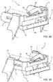
Figures 3A-3B are front perspective views of the stepladder offigure 2 in a first and a second operational positions; and -
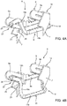
Figures 4A-4B are rear perspective views of the stepladder offigure 2 in further first and second operational positions. -
Figure 1 shows awork vehicle 1, e.g. an earth moving machine, comprising acabin 2 carried, preferably in a turntable way, by achassis 3. According to the described embodiment,chassis 3 is configured to move on ground thanks to atrack band transmission 5 carried around anundercarriage 4 fixedly carried bychassis 3. -
Vehicle 1 comprises, preferably carried byundercarriage 4 inside the loop defined by thetrack band transmission 5, astepladder 6 according to the innovation. Advantageously,work vehicle 1 may comprise more than asingle stepladder 6, in the disclosed embodiment it comprises a front and arear stepladders 6. - Making reference to
figure 2 ,stepladder 6 comprises at least asupport 7 configured to be fixed to a portion of the vehicle fixed tochassis 3, i.e. to undercarriage 4 as disclosed, and anextractable portion 8 carried in movable manner bysupport 7. In greater particular,stepladder 6 comprises a right and aleft supports 7 configured to carryextractable portion 8 within the space defined between themselves. - In greater particular, each
support 7 comprises abase portion 7a configured to be fixed tochassis 3 and atop portion 7b configured to carryextractable portion 8. Preferably,support 7 comprises a single plate-wall element defining the aforementioned base andtop portions other support 7. More preferably, such plate-wall element are equally spaced one with respect to the other about an axis A, perpendicular to undercarriage 4. Advantageously,supports 7 are made in metallic material and may be fixed tochassis 3 thanks to any known fixation device, e.g. bolts, welding etc. -
Extractable portion 8 essentially comprises amain portion 9 that is carried in the above-mentioned movable manner with respect to supports 7. In particular,main portion 9 comprises a pair oflateral walls 9a and afront wall 9b, connected together and preferably realized as one piece, more preferably in metal material. In more detail, lateral andfront walls - Optionally,
front wall 9b is provided with agrip portion 10 configured to allow a safe and antislip step for a user using thestepladder 6. In detail,grip portion 10 may comprise a plurality ofteeth 11 realized in a top edge offront wall 9b.Lateral walls 9a are faced one with respect to the other and equally spaced with respect to axis A at a distance so that they can cooperate withsupports 7 as described hereunder. - The movement of
extractable portion 8 is a translational movement, which is advantageously linear and realized along direction of axis A thanks to a slidingconnection 12 realized between eachsupport 7 and the respectivelateral wall 9a. - Preferably sliding
connection 12 comprises apin 13 carried by one betweensupport 7 orlateral wall 9a configured to slide in aguide 14 realized in the other of the aforementioned elements. In the described embodiment,pin 13 is realized intop portion 7b ofsupport 7 whileguide 14 is realized inlateral wall 9a. - Preferably,
lateral guide 14 has a substantially rectangular shape extending along axis A and comprising arear terminal edge 14a and afront terminal edge 14b.Pin 13 is configured to slide: - from
rear terminal edge 14a (figure 2 ) into whichextractable portion 8 is extracted with respect to supports 7, i.e.lateral walls 9a protrude laterally with respect tochassis 3, - to a
front terminal edge 14b (seefigures 3A ,4A and 4B ) into whichextractable portion 8 is placed inside the space defined bysupports 7, i.e.lateral walls 9a do not protrude laterally with respect tochassis 3. - Obviously, the aforementioned movement may also be realized vice versa, i.e. from front to
rear terminal edges -
Sliding connection 12 may further comprise anti-overturning means 16 configured to avoid a rotation ofextractable portion 8 about the above-disclosedpin 13. In particular, such anti-overturning means 16 may comprise an lip-shaped edge 17 extending fromtop portion 7b of therelated support 7 perpendicularly towards theopposite support 7. - Lip-
shaped edge 17 extends laterally along all lateral extension ofsupport 7 and it is configured to cooperated at contact with a top edge oflateral wall 9a thereby avoiding a rotation of this latter aroundpin 13. -
Extractable portion 8 further comprises anauxiliary portion 19 carried in movable manner bymain portion 9. In particular, suchauxiliary portion 19 comprises a pair oflateral walls 19a and afront wall 19b, connected together and preferably realized as one piece, more preferably in metal material. In more detail, lateral andfront walls - Optionally,
front wall 19b is provided with agrip portion 10 configured to allow a safe and antislip step for a user using thestepladder 6. In detail,grip portion 10 may comprise a plurality ofteeth 11 realized in a top edge offront wall 19b.Lateral walls 9a are instead faced one with respect to the other and equally spaced with respect to axis A at a distance so that they can cooperate with mainlateral walls 9a ofmain portion 9 as described hereinafter. - Preferably,
lateral walls 19a ofauxiliary portion 19 have a substantially L-shaped shape, i.e. comprises two linear segments, a longer and a shorter segment, connected perpendicularly together and preferably realized as one piece. -
Auxiliary portion 19 is carried in a movable manner so that it can reach a first, closed, position into which it is placed substantially inside the space surrounded bymain portion 9 and a second, opened, position into which it is spaced with respect tomain portion 9. - According to the described embodiment,
auxiliary portion 19 is carried pivotally with respect tomain portion 9 so that in the firstposition front portion 19a is placed substantially vertically underfront portion 9a of main portion (seefigures 3A, 3B ,4A ), or in a rear portion with respect tofront portion 9a along axis A(alternative not shown). - According to the described configuration, a
pivotable connection 21 is realized between main andauxiliary portion hole 22 realized in one between these latter configured to house in a sliding manner apin 23 realized in the other of these latter. Preferably,pin 23 is carried by lateral wall ofmain portion 9 whilehole 22 is realized at an extremity of L-shapedlateral walls 19a of auxiliary portion, i.e. into the low-length segment. - Therefore, low-length segment of L-shaped
lateral walls 19a is placed parallel tolateral wall 9a ofmain portion 9, preferably with both lower edges substantially at the same height, when auxiliary portion is in its second, opened, position. - As shown in
figures 3A ,4A and 4B stepladder 6 further comprises stop means 25 configured to limit the movement ofauxiliary portion 19 with respect tomain portion 9 ofextractable portion 8. In particular, such stop means 25 may comprise apin 26 fixedly carried bylateral support 7, preferably realized between base andtop portions support 7 towards the opposite.Such pin 26 is configured to cooperate at contact with auxiliary portion to avoid an excessive movement, i.e. pivoting, of this latter aroundpin 23. - Furthermore, as shown in
figures 3A-B and4A-B ,stepladder 6 further comprises elastic means 27 configured to maintain auxiliary portion in its first position with respect tomain portion 9. According to the described embodiment, elastic means 27 comprises aspring 28 carried bymain portion 9 and configured to exert a force onauxiliary portion 19 so that, if no force is applied onfront portion 19b, it is maintained into its first position. If a force, e.g. the force of a man pushing with a foot for jumping on the ladder, is applied tofront portion 19b,spring 28 is designed so that it will surrender, thereby allowing the movement of auxiliary portion from first to second position. - The operation of the above-described
stepladder 6 according to the innovation is described hereinafter referring tofigures 3A- B and4A- B . -
Figures 3A ,4A show a totally closed and retractedstepladder 6 configuration. In such configuration, the lateral space occupied bystepladder 6 is minimal and it is contained substantially all inside with respect to the loop defined bytrack band transmission 5. In Such configuration may be useful when thework vehicle 1 is working and there is no peculiar need to the user to enter in the cabin; the main need in such configuration is to provide the minimal occupied space, i.e. allowing, if necessary, a tall user to use the step, with a limited length of shoes (since themain portion 9 is not totally cantilevered with respect to supports 7). -
Figure 3B showsstepladder 6 in a first intermediate extended configuration. In such configuration, themain portion 9 is totally extracted with respect tosupports 7, i.e.pin 13 cooperates at contact withedge 14a ofguide 14, whileauxiliary portion 19 is still in its closed configuration, i.e. whereinfront wall 19a is placed just under/rear with respect tofront wall 9a ofmain portion 9. Such configuration may be useful for allowing a tall user to reachcabin 2 of the vehicle while allowing a great width of shoes of the track band, since the step defined bygrip portion 10 ofmain portion 9 is cantilevered outside with respect tochassis 3 and allows the user to use this latter as step, i.e. with a bigger width of shoes of the track band. -
Figure 4B showsstepladder 6 in a second intermediate opened configuration. In such configuration, themain portion 9 is in its closed position with respect tosupports 7, i.e.pin 13 cooperates at contact withedge 14b ofguide 14, whileauxiliary portion 19 is in its opened configuration, i.e. whereinfront wall 19a is spaced with respect tofront wall 9a ofmain portion 9. Such configuration may be useful for allowing a short user to reachcabin 2 of the vehicle, while, at the same time, maintaining a low level of lateral encumbrance. -
Figure 2 shows a totally openedstepladder 6 configuration. In such configuration, themain portion 9 is totally extracted with respect tosupports 7, i.e.pin 13 cooperates at contact withedge 14a ofguide 14, and alsoauxiliary portion 19 is in its opened configuration, i.e. whereinfront wall 19a is spaced with respect tofront wall 9a ofmain portion 9. Such configuration may be useful for furnishing a plurality of stables and different heights steps to the user, e.g. when the vehicle is standstill, allowing tall and short users, with different width of shoes of the track band, to enter into the cabin. - In view of the foregoing, the advantages of a
stepladder 6 according to the innovation are evident. - First, the disclosed
stepladder 6 allows a plurality ofcomfortable supports 7 to any user which has to access to thecabin 2 ofvehicle 1. - Furthermore, such support points, given by
front walls auxiliary portions - Moreover, the proposed layout can be realized in an economic way by using simple mechanical elements such as hinges or slides.
- Again, the proposed
stepladder 6 may be used on different vehicles layout, avoiding the use of additional steps, thereby further increasing cost savings during manufacturing of the work vehicle. - It is clear that modifications can be made to the described
stepladder 6 which do not extend beyond the scope of protection defined by the claims. - For example, the shape of main and
auxiliary portions supports 7 may be varied and, clearly,main portion 9 may slide in any intermediate position between the totally "closed" and the "opened" position of the latter. - Similarly, sliding
means 12, stop means 25 orelastic means 27 may be substituted by equivalent means. - Furthermore, the described relative movements of
main portion 9 with respect tosupports 7 or ofauxiliary portion 19 with respect tomain portion 9 can be varied in typology and dimensions according to the vehicles into which the stepladder has to be applied.
Claims (13)
- Stepladder (6) for a work vehicle (1) comprising a support (7) configured to carry in a movable manner an extractable portion (8), said extractable portion (8) comprising a main portion (9) carried by said support (7) and configured to move between a first closed position into which it is partially contained in said support (7) and a second open position into which it is cantilevered outside said portion (7), said extractable portion (8) further comprising an auxiliary portion (19) carried in movable manner by said main portion (9) and configured to assume a a first closed position into which it is partially contained within said main portion (9) and a second open position into which it is placed outside said main portion (9), wherein both main and auxiliary portions (9, 19) are configured to define a step.
- Stepladder according to claim 1, wherein said main portion (9) is carried by said support (7) in a translational way.
- Stepladder according to claim 1 or 2, wherein said auxiliary portion (19) is pivoted with respect to said main portion (9).
- Stepladder according to any of the preceding claims, wherein said main and auxiliary portions (9, 19) each comprises a pair of lateral walls (9a, 19a) and a front wall (9b, 19b), said front walls (9b, 19b) defining respective steps of said stepladder (6).
- Stepladder according to claim 4, wherein said steps comprises a grip portion (10).
- Stepladder according to claim 5, wherein said grip portion (10) comprises a plurality of teeth (11).
- Stepladder according to any of claims 2 to 6, comprising sliding means (12) configured to allow the translational movement of said main portion (9) with respect to said support (7).
- Stepladder according to claim 7, wherein said sliding means (12) comprise a pin (13) carried by one between support (7) and main portion (9) suitable for sliding into a guide (14) realized in the other between support (7) and main portion (9) .
- Stepladder according to claim 7 or 8, wherein said sliding means (12) further comprise anti-overturning means (16) configured to avoid a rotation of main portion (9) with respect to said support (7).
- Stepladder according to any of claims 3 to 9, further comprising stop means (25) configured to avoid a excessive rotation of said auxiliary portion (19) with respect to said main portion (9).
- Stepladder according to any of the preceding claims, further comprising elastic means (27) configured to exert a force configured to maintain said auxiliary portion (19) in its closed position.
- Stepladder according to any of the preceding claims, wherein said support (7) comprises a pair of plate-wall elements equally spaced with respect to a common axis (A), said extractable portion (8) being house within said space defined by said pair of plate-wall elements.
- Vehicle comprising a chassis (3) and a cabin (2) carried by said chassis (3), this latter further fixedly carrying a stepladder (6) according to any of the preceding claims.
Applications Claiming Priority (1)
| Application Number | Priority Date | Filing Date | Title |
|---|---|---|---|
| IT201900002316 | 2019-07-12 |
Publications (1)
| Publication Number | Publication Date |
|---|---|
| EP3763570A1 true EP3763570A1 (en) | 2021-01-13 |
Family
ID=71737987
Family Applications (1)
| Application Number | Title | Priority Date | Filing Date |
|---|---|---|---|
| EP20185420.5A Withdrawn EP3763570A1 (en) | 2019-07-12 | 2020-07-13 | Stepladder for a work vehicle |
Country Status (1)
| Country | Link |
|---|---|
| EP (1) | EP3763570A1 (en) |
Citations (7)
| Publication number | Priority date | Publication date | Assignee | Title |
|---|---|---|---|---|
| US3986503A (en) | 1975-09-22 | 1976-10-19 | Caterpillar Tractor Co. | Mounting means for machines |
| US5205603A (en) * | 1992-02-24 | 1993-04-27 | Burdette Jr Orin F | Truck tailgate ladder apparatus |
| US7025174B1 (en) * | 2003-08-20 | 2006-04-11 | Hawley James K | Truck ladder |
| US20080143072A1 (en) * | 2006-12-19 | 2008-06-19 | Parker Rick J | Step Device for Accessing a Truck Bed |
| US20150224936A1 (en) * | 2013-02-22 | 2015-08-13 | Rom Acquisition Corporation | Cargo truck multi-stage extendable personnel platform with foldable guardrail |
| EP3006267A1 (en) * | 2014-10-09 | 2016-04-13 | Manitou Italia S.r.l. | An apparatus for gaining access to lift vehicles |
| EP3275734A1 (en) | 2015-03-23 | 2018-01-31 | Komatsu Ltd. | Vertically-movable steps for working vehicles |
-
2020
- 2020-07-13 EP EP20185420.5A patent/EP3763570A1/en not_active Withdrawn
Patent Citations (7)
| Publication number | Priority date | Publication date | Assignee | Title |
|---|---|---|---|---|
| US3986503A (en) | 1975-09-22 | 1976-10-19 | Caterpillar Tractor Co. | Mounting means for machines |
| US5205603A (en) * | 1992-02-24 | 1993-04-27 | Burdette Jr Orin F | Truck tailgate ladder apparatus |
| US7025174B1 (en) * | 2003-08-20 | 2006-04-11 | Hawley James K | Truck ladder |
| US20080143072A1 (en) * | 2006-12-19 | 2008-06-19 | Parker Rick J | Step Device for Accessing a Truck Bed |
| US20150224936A1 (en) * | 2013-02-22 | 2015-08-13 | Rom Acquisition Corporation | Cargo truck multi-stage extendable personnel platform with foldable guardrail |
| EP3006267A1 (en) * | 2014-10-09 | 2016-04-13 | Manitou Italia S.r.l. | An apparatus for gaining access to lift vehicles |
| EP3275734A1 (en) | 2015-03-23 | 2018-01-31 | Komatsu Ltd. | Vertically-movable steps for working vehicles |
Similar Documents
| Publication | Publication Date | Title |
|---|---|---|
| RU2572975C1 (en) | Mechanism of luggage rack movement | |
| US8365798B2 (en) | Privacy screen assembly | |
| KR101962399B1 (en) | Antenna mast apparatus | |
| EP2249682B1 (en) | Anti-tip device and cabinet | |
| KR101477999B1 (en) | Open roof construction for a vehicle | |
| CN105501128A (en) | Apparatus for gaining access to lift vehicles | |
| DE202016102015U1 (en) | Lifting mechanism of a desk | |
| TW201938070A (en) | Slide rail assembly | |
| KR102463049B1 (en) | Windows regulator for vehicle | |
| JP6891608B2 (en) | Sunshade device | |
| EP3262978A1 (en) | Furniture with retractable worktop | |
| DE19946629A1 (en) | Stowage box, especially roof stowage box in motor vehicle, has facility whereby after box is totally lowered it is additionally inclined downwards in open position so that accessible front end tilts down further than other end | |
| WO2013135231A1 (en) | Slide housing for an electronic communication appliance | |
| DE102009045095C5 (en) | Housing with flap | |
| EP2980318A2 (en) | Working vehicle | |
| EP0958961A2 (en) | Tray for the dashboard of an automotive vehicle | |
| DE19930432C2 (en) | Folding table for a vehicle | |
| KR100860338B1 (en) | Munon stop with adjustable width | |
| KR101437266B1 (en) | Horizontal level adjustable ladder | |
| WO2009072865A2 (en) | Extensible table with improved extension mechanism | |
| JP2011138910A (en) | Rack for equipment storage | |
| CN218001735U (en) | Fan module and split type cigarette machine | |
| DE102011109552B4 (en) | Fitting system for guiding a flap of a piece of furniture and a piece of furniture with this | |
| KR200458987Y1 (en) | Table with an angle-adjustable table top | |
| JP2006519134A (en) | Vehicle shelf assembly |
Legal Events
| Date | Code | Title | Description |
|---|---|---|---|
| PUAI | Public reference made under article 153(3) epc to a published international application that has entered the european phase |
Free format text: ORIGINAL CODE: 0009012 |
|
| STAA | Information on the status of an ep patent application or granted ep patent |
Free format text: STATUS: THE APPLICATION HAS BEEN PUBLISHED |
|
| AK | Designated contracting states |
Kind code of ref document: A1 Designated state(s): AL AT BE BG CH CY CZ DE DK EE ES FI FR GB GR HR HU IE IS IT LI LT LU LV MC MK MT NL NO PL PT RO RS SE SI SK SM TR |
|
| AX | Request for extension of the european patent |
Extension state: BA ME |
|
| STAA | Information on the status of an ep patent application or granted ep patent |
Free format text: STATUS: REQUEST FOR EXAMINATION WAS MADE |
|
| 17P | Request for examination filed |
Effective date: 20210713 |
|
| RBV | Designated contracting states (corrected) |
Designated state(s): AL AT BE BG CH CY CZ DE DK EE ES FI FR GB GR HR HU IE IS IT LI LT LU LV MC MK MT NL NO PL PT RO RS SE SI SK SM TR |
|
| STAA | Information on the status of an ep patent application or granted ep patent |
Free format text: STATUS: THE APPLICATION IS DEEMED TO BE WITHDRAWN |
|
| 18D | Application deemed to be withdrawn |
Effective date: 20210714 |