EP3763501A1 - Mold for prepreg lamination and prepreg lamination method - Google Patents
Mold for prepreg lamination and prepreg lamination method Download PDFInfo
- Publication number
- EP3763501A1 EP3763501A1 EP19820249.1A EP19820249A EP3763501A1 EP 3763501 A1 EP3763501 A1 EP 3763501A1 EP 19820249 A EP19820249 A EP 19820249A EP 3763501 A1 EP3763501 A1 EP 3763501A1
- Authority
- EP
- European Patent Office
- Prior art keywords
- mold
- prepreg
- bent part
- tape
- along
- Prior art date
- Legal status (The legal status is an assumption and is not a legal conclusion. Google has not performed a legal analysis and makes no representation as to the accuracy of the status listed.)
- Withdrawn
Links
- 238000003475 lamination Methods 0.000 title claims abstract description 55
- 238000000034 method Methods 0.000 title claims description 13
- 238000005056 compaction Methods 0.000 claims description 12
- 238000010030 laminating Methods 0.000 description 21
- 239000002131 composite material Substances 0.000 description 7
- 238000007906 compression Methods 0.000 description 7
- 239000000463 material Substances 0.000 description 6
- 230000003247 decreasing effect Effects 0.000 description 4
- 230000006835 compression Effects 0.000 description 3
- 239000000835 fiber Substances 0.000 description 2
- 238000004519 manufacturing process Methods 0.000 description 2
- 230000000694 effects Effects 0.000 description 1
- 239000012467 final product Substances 0.000 description 1
- 238000000465 moulding Methods 0.000 description 1
- 239000000047 product Substances 0.000 description 1
- 230000037303 wrinkles Effects 0.000 description 1
Images


Classifications
-
- B—PERFORMING OPERATIONS; TRANSPORTING
- B32—LAYERED PRODUCTS
- B32B—LAYERED PRODUCTS, i.e. PRODUCTS BUILT-UP OF STRATA OF FLAT OR NON-FLAT, e.g. CELLULAR OR HONEYCOMB, FORM
- B32B37/00—Methods or apparatus for laminating, e.g. by curing or by ultrasonic bonding
- B32B37/0046—Methods or apparatus for laminating, e.g. by curing or by ultrasonic bonding characterised by constructional aspects of the apparatus
-
- B—PERFORMING OPERATIONS; TRANSPORTING
- B29—WORKING OF PLASTICS; WORKING OF SUBSTANCES IN A PLASTIC STATE IN GENERAL
- B29C—SHAPING OR JOINING OF PLASTICS; SHAPING OF MATERIAL IN A PLASTIC STATE, NOT OTHERWISE PROVIDED FOR; AFTER-TREATMENT OF THE SHAPED PRODUCTS, e.g. REPAIRING
- B29C33/00—Moulds or cores; Details thereof or accessories therefor
- B29C33/38—Moulds or cores; Details thereof or accessories therefor characterised by the material or the manufacturing process
-
- B—PERFORMING OPERATIONS; TRANSPORTING
- B29—WORKING OF PLASTICS; WORKING OF SUBSTANCES IN A PLASTIC STATE IN GENERAL
- B29C—SHAPING OR JOINING OF PLASTICS; SHAPING OF MATERIAL IN A PLASTIC STATE, NOT OTHERWISE PROVIDED FOR; AFTER-TREATMENT OF THE SHAPED PRODUCTS, e.g. REPAIRING
- B29C33/00—Moulds or cores; Details thereof or accessories therefor
- B29C33/42—Moulds or cores; Details thereof or accessories therefor characterised by the shape of the moulding surface, e.g. ribs or grooves
-
- B—PERFORMING OPERATIONS; TRANSPORTING
- B29—WORKING OF PLASTICS; WORKING OF SUBSTANCES IN A PLASTIC STATE IN GENERAL
- B29C—SHAPING OR JOINING OF PLASTICS; SHAPING OF MATERIAL IN A PLASTIC STATE, NOT OTHERWISE PROVIDED FOR; AFTER-TREATMENT OF THE SHAPED PRODUCTS, e.g. REPAIRING
- B29C43/00—Compression moulding, i.e. applying external pressure to flow the moulding material; Apparatus therefor
- B29C43/02—Compression moulding, i.e. applying external pressure to flow the moulding material; Apparatus therefor of articles of definite length, i.e. discrete articles
- B29C43/20—Making multilayered or multicoloured articles
- B29C43/203—Making multilayered articles
-
- B—PERFORMING OPERATIONS; TRANSPORTING
- B29—WORKING OF PLASTICS; WORKING OF SUBSTANCES IN A PLASTIC STATE IN GENERAL
- B29C—SHAPING OR JOINING OF PLASTICS; SHAPING OF MATERIAL IN A PLASTIC STATE, NOT OTHERWISE PROVIDED FOR; AFTER-TREATMENT OF THE SHAPED PRODUCTS, e.g. REPAIRING
- B29C43/00—Compression moulding, i.e. applying external pressure to flow the moulding material; Apparatus therefor
- B29C43/32—Component parts, details or accessories; Auxiliary operations
- B29C43/34—Feeding the material to the mould or the compression means
-
- B—PERFORMING OPERATIONS; TRANSPORTING
- B29—WORKING OF PLASTICS; WORKING OF SUBSTANCES IN A PLASTIC STATE IN GENERAL
- B29C—SHAPING OR JOINING OF PLASTICS; SHAPING OF MATERIAL IN A PLASTIC STATE, NOT OTHERWISE PROVIDED FOR; AFTER-TREATMENT OF THE SHAPED PRODUCTS, e.g. REPAIRING
- B29C43/00—Compression moulding, i.e. applying external pressure to flow the moulding material; Apparatus therefor
- B29C43/32—Component parts, details or accessories; Auxiliary operations
- B29C43/36—Moulds for making articles of definite length, i.e. discrete articles
-
- B—PERFORMING OPERATIONS; TRANSPORTING
- B29—WORKING OF PLASTICS; WORKING OF SUBSTANCES IN A PLASTIC STATE IN GENERAL
- B29C—SHAPING OR JOINING OF PLASTICS; SHAPING OF MATERIAL IN A PLASTIC STATE, NOT OTHERWISE PROVIDED FOR; AFTER-TREATMENT OF THE SHAPED PRODUCTS, e.g. REPAIRING
- B29C70/00—Shaping composites, i.e. plastics material comprising reinforcements, fillers or preformed parts, e.g. inserts
- B29C70/04—Shaping composites, i.e. plastics material comprising reinforcements, fillers or preformed parts, e.g. inserts comprising reinforcements only, e.g. self-reinforcing plastics
- B29C70/06—Fibrous reinforcements only
- B29C70/10—Fibrous reinforcements only characterised by the structure of fibrous reinforcements, e.g. hollow fibres
- B29C70/16—Fibrous reinforcements only characterised by the structure of fibrous reinforcements, e.g. hollow fibres using fibres of substantial or continuous length
-
- B—PERFORMING OPERATIONS; TRANSPORTING
- B29—WORKING OF PLASTICS; WORKING OF SUBSTANCES IN A PLASTIC STATE IN GENERAL
- B29C—SHAPING OR JOINING OF PLASTICS; SHAPING OF MATERIAL IN A PLASTIC STATE, NOT OTHERWISE PROVIDED FOR; AFTER-TREATMENT OF THE SHAPED PRODUCTS, e.g. REPAIRING
- B29C70/00—Shaping composites, i.e. plastics material comprising reinforcements, fillers or preformed parts, e.g. inserts
- B29C70/04—Shaping composites, i.e. plastics material comprising reinforcements, fillers or preformed parts, e.g. inserts comprising reinforcements only, e.g. self-reinforcing plastics
- B29C70/28—Shaping operations therefor
- B29C70/30—Shaping by lay-up, i.e. applying fibres, tape or broadsheet on a mould, former or core; Shaping by spray-up, i.e. spraying of fibres on a mould, former or core
- B29C70/38—Automated lay-up, e.g. using robots, laying filaments according to predetermined patterns
- B29C70/386—Automated tape laying [ATL]
-
- B—PERFORMING OPERATIONS; TRANSPORTING
- B29—WORKING OF PLASTICS; WORKING OF SUBSTANCES IN A PLASTIC STATE IN GENERAL
- B29C—SHAPING OR JOINING OF PLASTICS; SHAPING OF MATERIAL IN A PLASTIC STATE, NOT OTHERWISE PROVIDED FOR; AFTER-TREATMENT OF THE SHAPED PRODUCTS, e.g. REPAIRING
- B29C70/00—Shaping composites, i.e. plastics material comprising reinforcements, fillers or preformed parts, e.g. inserts
- B29C70/04—Shaping composites, i.e. plastics material comprising reinforcements, fillers or preformed parts, e.g. inserts comprising reinforcements only, e.g. self-reinforcing plastics
- B29C70/28—Shaping operations therefor
- B29C70/40—Shaping or impregnating by compression not applied
- B29C70/42—Shaping or impregnating by compression not applied for producing articles of definite length, i.e. discrete articles
- B29C70/46—Shaping or impregnating by compression not applied for producing articles of definite length, i.e. discrete articles using matched moulds, e.g. for deforming sheet moulding compounds [SMC] or prepregs
-
- B—PERFORMING OPERATIONS; TRANSPORTING
- B32—LAYERED PRODUCTS
- B32B—LAYERED PRODUCTS, i.e. PRODUCTS BUILT-UP OF STRATA OF FLAT OR NON-FLAT, e.g. CELLULAR OR HONEYCOMB, FORM
- B32B38/00—Ancillary operations in connection with laminating processes
- B32B38/08—Impregnating
-
- B—PERFORMING OPERATIONS; TRANSPORTING
- B29—WORKING OF PLASTICS; WORKING OF SUBSTANCES IN A PLASTIC STATE IN GENERAL
- B29K—INDEXING SCHEME ASSOCIATED WITH SUBCLASSES B29B, B29C OR B29D, RELATING TO MOULDING MATERIALS OR TO MATERIALS FOR MOULDS, REINFORCEMENTS, FILLERS OR PREFORMED PARTS, e.g. INSERTS
- B29K2105/00—Condition, form or state of moulded material or of the material to be shaped
- B29K2105/06—Condition, form or state of moulded material or of the material to be shaped containing reinforcements, fillers or inserts
- B29K2105/08—Condition, form or state of moulded material or of the material to be shaped containing reinforcements, fillers or inserts of continuous length, e.g. cords, rovings, mats, fabrics, strands or yarns
- B29K2105/0872—Prepregs
- B29K2105/0881—Prepregs unidirectional
Definitions
- the present invention relates to a mold for prepreg lamination and a prepreg lamination method.
- AFP automated fiber laminating device
- ATL automated tape laminating device
- PTL 1 discloses a technique of manufacturing a mold based on a mold model, in which, as a result of the press molding, the shape of the mold model is modified such that wrinkles or cracks do not occur in a prepreg laminated product.
- PTL 2 discloses a technique relating to a composite spar for an aircraft wing including a web, an upper flange, and a lower flange, in which a region where there is too little or too much material is reduced in a final product by twisting a web surface so that a decrease in strength is suppressed.
- a mold 50 for forming a molded article has an upper surface 51 and a side surface 52.
- a prepreg tape 61 in a case where a prepreg tape 61 is compressed from the upper surface 51 toward the side surface 52 (or from the side surface 52 to the upper surface 51) of the mold 50 by the laminating device such as AFP, a plurality of tapes 61 can be compressed without generating a gap or a wrap (overlapping), on a portion where there is no bent part in a length direction on both the side surface 52 and the upper surface 51.
- the plurality of tapes 61 are attached in parallel with a vertical direction on surfaces 52A and 52C.
- the bent part is formed on the surface (side surface) of the mold.
- bent parts 53 and 54 are formed.
- the side surfaces 52A and 52C on one side are inclined with respect to the other surface 52B with the bent parts 53 and 54 as boundaries.
- the strength of the molded article may be decreased or the surface of the molded article may have irregularities as compared with a case where the prepreg is uniformly laminated.
- this method it is necessary to narrow the width of the tape fed from the head of the laminating device or to reduce the number of tapes to be fed, the width and the number of tapes which can be compressed at the same time are reduced, and thus repetition of a compression process is increased. Accordingly, there is a problem that the time required for lamination is increased.
- the invention is made in view of such circumstances, and an object of the invention is to provide a mold for prepreg lamination and a prepreg lamination method which can reduce the gap generated between the plurality of tapes or the overlapping of the plurality of tapes by reducing the direction deviation of the attachment direction of the tape in a case where the prepreg tape is compressed on the surface of the mold having a bent part.
- a mold for prepreg lamination and a prepreg lamination method of the invention adopt the following means.
- a mold for prepreg lamination includes a first surface having only a flat surface along one direction; a second surface which has a flat surface along the one direction and is disposed at a predetermined angle with respect to the first surface; and a third surface in which a cross-sectional shape of a surface cut in a direction orthogonal to the one direction is an arc, and which has one end side connected to the first surface and the other end side connected to the second surface, in which, in the second surface and the third surface, a protruding first bent part is formed, and one surface is inclined with respect to the other surface with the first bent part as a boundary, and a diameter of the arc of the other surface of the third surface is gradually reduced as a distance from the first bent part is increased along the one direction.
- the third surface has one end side connected to the first surface having only a flat surface along the one direction, and the other end side connected to the second surface having only a flat surface along the one direction.
- the cross-sectional shape of the surface cut in a direction orthogonal to the one direction is an arc
- the protruding first bent part is formed, and the one surface is inclined with respect to the other surface with the first bent part as a boundary.
- the diameter of the arc of the other surface of the third surface is gradually reduced as the distance from the first bent part is increased along the one direction.
- the attachment direction of the tape in the second surface is less likely to be inclined with respect to the vertical direction. Therefore, overlapping (wrap) of a plurality of tapes is reduced.
- a mold for prepreg lamination according to a second aspect of the invention includes a first surface having only a flat surface along one direction; a second surface which has a flat surface along the one direction and is disposed at a predetermined angle with respect to the first surface; and a third surface in which a cross-sectional shape of a surface cut in a direction orthogonal to the one direction is an arc, and which has one end side connected to the first surface and the other end side connected to the second surface, in which, in the second surface and the third surface, a recessed second bent part is formed, and one surface is inclined with respect to the other surface with the second bent part as a boundary, and a diameter of the arc of the other surface of the third surface is gradually increased as a distance from the second bent part is increased along the one direction.
- the third surface has one end side connected to the first surface having only a flat surface along the one direction, and the other end side connected to the second surface having only a flat surface along the one direction.
- the cross-sectional shape of the surface cut in a direction orthogonal to the one direction is an arc
- the recessed second bent part is formed, and the one surface is inclined with respect to the other surface with the second bent part as a boundary.
- the diameter of the arc of the other surface of the third surface is gradually increased as the distance from the second bent part is increased along the one direction.
- the attachment direction of the tape in the second surface is less likely to be inclined with respect to the vertical direction. Therefore, the gap generated between a plurality of tapes is reduced.
- the first bent part or the second bent part may have a curved portion having a curved shape, and may be connected to the one surface and the other surface through the curved portion.
- the contact surface of the roller is elastically deformed, and the contact surface comes into contact with flat portions on both sides with the bent part interposed therebetween, so that the tape can be compressed more.
- a mold for prepreg lamination according to a third aspect of the invention includes a first surface having only a flat surface along one direction; a second surface which has a flat surface along the one direction and is disposed at a predetermined angle with respect to the first surface; and a third surface in which a cross-sectional shape of a surface cut in a direction orthogonal to the one direction is an arc, and which has one end side connected to the first surface and the other end side connected to the second surface, in which, in the second surface and the third surface, a protruding or recessed bent part is formed, and one surface is inclined with respect to the other surface with the bent part as a boundary, and the bent part has a curved portion having a curved shape, and is connected to the one surface and the other surface through the curved portion.
- the third surface has one end side connected to the first surface having only a flat surface along the one direction, and the other end side connected to the second surface having only a flat surface along the one direction.
- the cross-sectional shape of the surface cut in a direction orthogonal to the one direction is an arc, and in the second surface and the third surface, the protruding or recessed bent part is formed, and the one surface is inclined with respect to the other surface with the bent part as a boundary.
- a prepreg lamination method includes a step of attaching a tape-shaped prepreg tape to the first surface or the second surface of the above-described mold for prepreg lamination, and then attaching the prepreg tape to the third surface; and a step of attaching the prepreg tape to the second surface or the first surface after attaching the prepreg tape to the third surface.
- a prepreg lamination method includes a step of attaching a tape-shaped prepreg tape to the curved portion and the one surface or the other surface of the above-described mold for prepreg lamination, and compressing the prepreg tape using a compaction roller.
- the mold for prepreg lamination 1 (hereinafter, referred to as a "mold 1") according to the embodiment is used in a case of laminating the prepreg, by a laminating device such as an automated fiber laminating device (AFP) or an automated tape laminating device (ATL).
- the laminating device such as the AFP feeds tape-shaped prepreg (hereinafter, referred to as "prepreg tape") 61 having a predetermined width to the surface of the mold for lamination.
- prepreg tape tape-shaped prepreg
- the prepreg laminated in a plurality of layers is cured to be formed as a molded article.
- the mold 1 for forming a molded article has a first surface 6 and a second surface 7.
- the prepreg tape 61 is attached to such a mold 1
- the prepreg tape 61 is attached from the first surface 6 toward the second surface 7 (or from the second surface 7 toward the first surface 6) of the mold 1 as illustrated in Fig. 2 .
- the prepreg tape 61 fed from the laminating device is attached while being compressed by the compaction roller.
- a plurality of prepreg tapes 61 are disposed side by side along a length direction of the mold 1.
- the mold 1 includes the first surface 6 having only a flat surface along the length direction, the second surface 7 which has a flat surface along the length direction and is disposed at a predetermined angle with respect to the first surface 6, and a third surface 8 formed between the first surface 6 and the second surface 7.
- the molded article formed by the mold 1 is a long material that is long in one direction. Further, in a case where the first surface 6 is dispose to face an upward direction and the second surface 7 is disposed to face a lateral direction, the first surface 6 becomes an upper surface and the second surface 7 becomes a side surface.
- the third surface 8 is a fillet surface, and is a curved surface in which the cross-sectional shape of the surface cut in a direction orthogonal to the length direction is an arc.
- the third surface 8 has one end side continuously connected to the first surface 6 and the other end side continuously connected to the second surface 7.
- the arc as the cross-sectional shape of the third surface 8 may be a part of a perfect circle or may be a part of an ellipse.
- protruding first bent parts 9 and 10 are respectively formed on the second surface 7 and the third surface 8.
- one surface 7B is inclined with respect to the other surface 7A with the protruding first bent part 9 as a boundary
- one surface 8B is inclined with respect to the other surface 8A with the protruding first bent part 10 as a boundary.
- the angle formed by the one surface 7B and the other surface 7A and the angle formed by the one surface 8B and the other surface 8A are greater than 180° and smaller than 270°.
- the first bent part 9 is a part where the surface 7A and the surface 7B are combined, and has a linear shape.
- the first bent part 10 is a part where the surface 8A and the surface 8B are combined, and has a curved shape.
- the diameter of the arc of the cross-sectional shape of the surface 8B of the third surface 8 is gradually reduced as the distance from the protruding first bent part 10 is increased along the length direction.
- the length of the side end portion of the tape 61 attached on the surface 8B of the third surface 8 is shorter on a side far from the first bent part 10 than a side close to the first bent part 10. Therefore, as illustrated in Fig.
- the attachment direction of the tape 61 in the surfaces 7A and 7B of the second surface 7 is less likely to be inclined with respect to the vertical direction as compared with a case where the arc of the cross-sectional shape of a surface 55B of a fillet surface 55 has the same diameter along the length direction as illustrated in Fig. 10 . Therefore, the direction deviation is reduced, and the overlapping (wrap) of the plurality of tapes 61 is reduced.
- the overlapping (wrap) of the plurality of tapes 61 is reduced, after the prepregs are laminated, the unevenness of the lamination thickness is reduced. As a result, the strength of the cured molded article is less likely to be decreased, and irregularities occurring on the surface of the molded article are reduced. Further, unlike a case of using the mold 50 in which the direction deviation of the tape 61 is large as illustrated in Fig. 10 , it is not necessary to narrow the width of the tape 61 fed from the head of the laminating device or to reduce the number of tapes 61 to be fed. Therefore, since it is not necessary to reduce the width or the number of tapes 61 which can be compressed at the same time, the repetition of the compression process is not increased, and the time required for lamination can be prevented from being increased.
- the mold for prepreg lamination 2 (hereinafter, referred as a "mold 2") according to the embodiment is used when a composite material molded article has a shape in which two plate materials are combined at a predetermined angle (for example, 90°) (for example, when a part of the cross section has an L shape), the mold 2 for forming a molded article has the first surface 6, the second surface 7, and the third surface 8.
- recessed second bent parts 11 and 12 are respectively formed on the second surface 7 and the third surface 8.
- one surface 7B is inclined with respect to the other surface 7C with the recessed second bent part 11 as a boundary
- one surface 8B is inclined with respect to the other surface 8C with the recessed second bent part 12 as a boundary.
- the angle formed by the one surface 7B and the other surface 7C and the angle formed by the one surface 8B and the other surface 8C are greater than 90° and smaller than 180°.
- the second bent part 11 is a part where the surface 7B and the surface 7C are combined, and has a linear shape.
- the second bent part 12 is a part where the surface 8B and the surface 8C are combined, and has a curved shape.
- the diameter of the arc of the cross-sectional shape of the surface 8B of the third surface 8 is gradually increased as the distance from the recessed second bent part 12 is increased along the length direction.
- the length of the side end portion of the tape 61 attached on the surface 8B of the third surface 8 is longer on a side far from the second bent part 12 than a side close to the second bent part 12. Therefore, as illustrated in Fig.
- the attachment direction of the tape 61 in the surface 7B of the second surface 7 is less likely to be inclined with respect to the vertical direction as compared with a case where the arc of the cross-sectional shape of the surface 55B of the fillet surface 55 has the same diameter along the length direction as illustrated in Fig. 10 . Therefore, the direction deviation is reduced, and the gap generated between the plurality of tapes 61 is reduced.
- the gap generated between the plurality of tapes 61 is reduced, after the prepregs are laminated, the strength of the cured molded article is less likely to be decreased and the irregularities occurring on the surface of the molded article are reduced. Further, unlike a case of using the mold 50 in which the direction deviation of the tape 61 is large, it is not necessary to narrow the width of the tape 61 fed from the head of the laminating device or to reduce the number of tapes 61 to be fed. Therefore, since it is not necessary to reduce the width or the number of tapes 61 which can be compressed at the same time, the repetition of the compression process is not increased, and the time required for lamination can be prevented from being increased.
- the mold for prepreg lamination 3 (hereinafter, referred as a "mold 3") according to the embodiment is used when a composite material molded article has a shape in which two plate materials are combined at a predetermined angle (for example, 90°) (for example, when a part of the cross section has an L shape), the mold 3 for forming a molded article has the first surface 6, the second surface 7, and the third surface 8.
- the protruding first bent parts 9 and 10 are respectively formed on the second surface 7 and the third surface 8
- the recessed second bent parts 11 and 12 are respectively formed on the second surface 7 and the third surface 8.
- a stepped part is formed on the outer surface of the molded article.
- the diameter of the arc of the cross-sectional shape of the surface 8B of the third surface 8 is gradually reduced as the distance from the protruding first bent part 10 is increased along the length direction, and is gradually increased as the distance from the recessed second bent part 12 is increased along the length direction. As illustrated in Fig.
- the length of the side end portion of the tape 61 attached on the surface 8B of the third surface 8 is shorter on a side far from the first bent part 10 than a side close to the first bent part 10, and the length of the side end portion of the tape 61 attached on the surface 8B of the third surface 8 is longer on a side far from the second bent part 12 than a side close to the second bent part 12.
- the length of the side end portion of the tape 61 attached on the surface 55B of the fillet surface 55 is substantially the same on a side close to the first bent part 10 and a side far from the first bent part 10. Therefore, the deviation of the attachment direction of the tape 61 is large in the side surface 52.
- the attachment direction of the tape 61 in the surfaces 7A and 7B of the second surface 7 is less likely to be inclined with respect to the vertical direction as compared with a case where the arc of the cross-sectional shape of the surface 55B of the fillet surface 55 has the same diameter along the length direction as illustrated in Fig. 10 . Therefore, the direction deviation is reduced, the overlapping (wrap) of the plurality of tapes 61 is reduced, and the gap generated between the plurality of tapes 61 is reduced.
- the overlapping (wrap) of the plurality of tapes 61 is reduced and the gap generated between the plurality of tapes 61 is reduced, after the prepregs are laminated, the unevenness of the lamination thickness is reduced. As a result, the strength of the cured molded article is less likely to be decreased, and irregularities occurring on the surface of the molded article are reduced. Further, unlike the case of using the mold 50 in which the direction deviation of the tape 61 is large, it is not necessary to narrow the width of the tape 61 fed from the head of the laminating device or to reduce the number of tapes 61 to be fed. Therefore, since it is not necessary to reduce the tapes 61 which can be compressed at the same time, the repetition of the compression process is not increased, and the time required for lamination can be prevented from being increased.
- the first bent part 9 or the second bent part 11 is a portion where both the flat surfaces 7A and 7B are combined or a portion where both the flat surfaces 7B and 7C are combined, and a straight line is formed in a ridge shape or a valley shape at the top of the protruding portion or the bottom of the recessed portion.
- the first bent part 10 or the second bent part 12 is a portion where both the curved surfaces 8A and 8B are combined or a portion where both the curved surfaces 8B and 8C are combined, and a curved line is formed in a ridge shape or a valley shape at the top of the protruding portion or the bottom of the recessed portion.
- a protruding curved portion 13 or a recessed curved portion 15 is formed such that a straight line is not formed at the top of the protruding portion or the bottom of the recessed portion.
- a protruding curved portion 14 or a recessed curved portion 16 is formed such that a curved line is not formed at the top of the protruding portion or the bottom of the recessed portion.
- the first bent part 9 is connected to the one surface 7A and the other surface 7B through the protruding curved portion 13
- the first bent part 10 is connected to the one surface 8A and the other surface 8B through the protruding curved portion 14.
- the second bent part 11 is connected to the one surface 7C and the other surface 7B through the recessed curved portion
- the second bent part 12 is connected to the one surface 8C and the other surface 8B through the recessed curved portion 16.
- the protruding curved portions 13 and 14 or the recessed curved portions 15 and 16 are fillet surfaces, and are curved surfaces in which the cross-sectional shape of the surface cut in a direction in parallel with the length direction is an arc.
- the one surface 7A and the other surface 7B are smoothly connected through the protruding curved portion 13, and the one surface 8A and the other surface 8B are smoothly connected through the protruding curved portion 14.
- the one surface 7C and the other surface 7B are smoothly connected through the recessed curved portion 15, and the one surface 8C and the other surface 8B are smoothly connected through the recessed curved portion 16.
- the arc as the cross-sectional shape of the protruding curved portions 13 and 14 or the recessed curved portions 15 and 16 may be a part of a perfect circle or may be a part of an ellipse.
- an angle formed by the tangent planes of the curved portions 13 and 14 and the one surfaces 7A and 8A of the first bent parts 9 and 10 is smaller than an angle formed by the one surfaces 7A and 8A and the other surfaces 7B and 7C of the first bent parts 9 and 10 in a case where the curved portions 13 and 14 are not provided.
- the direction of the tangent line of the protruding curved portions 13 and 14 or the recessed curved portions 15 and 16 is gradually changed along the length direction. It is easy for the contact surface of the compaction roller 70 to come into contact with the surface of the mold 4 or 5 on both sides of the first bent parts 9 and 10 or both sides of the second bent parts 11 and 12. Accordingly, it is possible reliably perform the compression of the tape 61 by the compaction roller 70 on both sides of the first bent parts 9 and 10 or both sides of the second bent parts 11 and 12.
Landscapes
- Engineering & Computer Science (AREA)
- Mechanical Engineering (AREA)
- Chemical & Material Sciences (AREA)
- Composite Materials (AREA)
- Robotics (AREA)
- Textile Engineering (AREA)
- Manufacturing & Machinery (AREA)
- Moulding By Coating Moulds (AREA)
- Casting Or Compression Moulding Of Plastics Or The Like (AREA)
- Moulds For Moulding Plastics Or The Like (AREA)
Abstract
Description
- The present invention relates to a mold for prepreg lamination and a prepreg lamination method.
- As a method of manufacturing a composite material, there is a technique of laminating a tape-shaped prepreg tape with a predetermined width multiple times on a mold using an automated fiber laminating device (AFP) or an automated tape laminating device (ATL). At this time, the tape fed from a head of the laminating device is compressed onto the mold by a compaction roller.
-
PTL 1 discloses a technique of manufacturing a mold based on a mold model, in which, as a result of the press molding, the shape of the mold model is modified such that wrinkles or cracks do not occur in a prepreg laminated product.PTL 2 discloses a technique relating to a composite spar for an aircraft wing including a web, an upper flange, and a lower flange, in which a region where there is too little or too much material is reduced in a final product by twisting a web surface so that a decrease in strength is suppressed. -
- [PTL 1] Japanese Patent No.
5260593 - [PTL 2] Japanese Patent No.
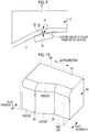
5686286 - As illustrated in
Fig. 10 , when a composite material molded article 60 has a shape in which two plate materials are combined at a predetermined angle (for example, 90°), amold 50 for forming a molded article has anupper surface 51 and aside surface 52. As illustrated inFig. 11 , in a case where aprepreg tape 61 is compressed from theupper surface 51 toward the side surface 52 (or from theside surface 52 to the upper surface 51) of themold 50 by the laminating device such as AFP, a plurality oftapes 61 can be compressed without generating a gap or a wrap (overlapping), on a portion where there is no bent part in a length direction on both theside surface 52 and theupper surface 51. In the example illustrated inFig. 11 , the plurality oftapes 61 are attached in parallel with a vertical direction onsurfaces - On the other hand, in a case of providing a part where the plate thickness is changed along the length direction to the composite material molded article or a case where providing a stepped part along the length direction (plate thicknesses t1 and t2 in
Fig. 10 ), the bent part is formed on the surface (side surface) of the mold. In themold 50 illustrated inFigs. 10 and11 ,bent parts mold 50, theside surfaces other surface 52B with thebent parts prepreg tape 61 is compressed from theupper surface 51 toward the side surface 52 (or from theside surface 52 to the upper surface 51) of themold 50 by the laminating device, a direction deviation is caused due to the inclination of an attachment direction of thetape 61, as illustrated inFig. 11 . As a result, a gap is generated between the plurality oftapes 61 or the plurality oftapes 61 overlap each other. - As a result, the strength of the molded article may be decreased or the surface of the molded article may have irregularities as compared with a case where the prepreg is uniformly laminated. There is a method of reducing the gap or overlapping generated between the tapes by steering a feed direction of the lamination tape or adding the lamination tape to the generated gap. However, in this method, it is necessary to narrow the width of the tape fed from the head of the laminating device or to reduce the number of tapes to be fed, the width and the number of tapes which can be compressed at the same time are reduced, and thus repetition of a compression process is increased. Accordingly, there is a problem that the time required for lamination is increased.
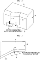
- As illustrated in
Figs. 12 and 13 , in a case where thebent parts mold 50, in thebent parts compaction roller 70 and themold 50, and thus the compression of the tape by thecompaction roller 70 tends to be insufficient. - The invention is made in view of such circumstances, and an object of the invention is to provide a mold for prepreg lamination and a prepreg lamination method which can reduce the gap generated between the plurality of tapes or the overlapping of the plurality of tapes by reducing the direction deviation of the attachment direction of the tape in a case where the prepreg tape is compressed on the surface of the mold having a bent part.
- In order to solve the problem, a mold for prepreg lamination and a prepreg lamination method of the invention adopt the following means.
- That is, a mold for prepreg lamination according to a first aspect of the invention includes a first surface having only a flat surface along one direction; a second surface which has a flat surface along the one direction and is disposed at a predetermined angle with respect to the first surface; and a third surface in which a cross-sectional shape of a surface cut in a direction orthogonal to the one direction is an arc, and which has one end side connected to the first surface and the other end side connected to the second surface, in which, in the second surface and the third surface, a protruding first bent part is formed, and one surface is inclined with respect to the other surface with the first bent part as a boundary, and a diameter of the arc of the other surface of the third surface is gradually reduced as a distance from the first bent part is increased along the one direction.
- With this configuration, the third surface has one end side connected to the first surface having only a flat surface along the one direction, and the other end side connected to the second surface having only a flat surface along the one direction. Further, in the third surface, the cross-sectional shape of the surface cut in a direction orthogonal to the one direction is an arc, and in the second surface and the third surface, the protruding first bent part is formed, and the one surface is inclined with respect to the other surface with the first bent part as a boundary. The diameter of the arc of the other surface of the third surface is gradually reduced as the distance from the first bent part is increased along the one direction. As a result, in a case where the prepreg tape is compressed from the first surface toward the second surface (or from the second surface toward the first surface) of the mold by the laminating device, the attachment direction of the tape in the second surface is less likely to be inclined with respect to the vertical direction. Therefore, overlapping (wrap) of a plurality of tapes is reduced.
- A mold for prepreg lamination according to a second aspect of the invention includes a first surface having only a flat surface along one direction; a second surface which has a flat surface along the one direction and is disposed at a predetermined angle with respect to the first surface; and a third surface in which a cross-sectional shape of a surface cut in a direction orthogonal to the one direction is an arc, and which has one end side connected to the first surface and the other end side connected to the second surface, in which, in the second surface and the third surface, a recessed second bent part is formed, and one surface is inclined with respect to the other surface with the second bent part as a boundary, and a diameter of the arc of the other surface of the third surface is gradually increased as a distance from the second bent part is increased along the one direction.
- With this configuration, the third surface has one end side connected to the first surface having only a flat surface along the one direction, and the other end side connected to the second surface having only a flat surface along the one direction. Further, in the third surface, the cross-sectional shape of the surface cut in a direction orthogonal to the one direction is an arc, and in the second surface and the third surface, the recessed second bent part is formed, and the one surface is inclined with respect to the other surface with the second bent part as a boundary. The diameter of the arc of the other surface of the third surface is gradually increased as the distance from the second bent part is increased along the one direction. As a result, in a case where the prepreg tape is compressed from the first surface toward the second surface (or from the second surface toward the first surface) of the mold by the laminating device, the attachment direction of the tape in the second surface is less likely to be inclined with respect to the vertical direction. Therefore, the gap generated between a plurality of tapes is reduced.
- In the first and second aspects, the first bent part or the second bent part may have a curved portion having a curved shape, and may be connected to the one surface and the other surface through the curved portion.
- With this configuration, in a case of compressing the prepreg tape by the compaction roller, the contact surface of the roller is elastically deformed, and the contact surface comes into contact with flat portions on both sides with the bent part interposed therebetween, so that the tape can be compressed more.
- A mold for prepreg lamination according to a third aspect of the invention includes a first surface having only a flat surface along one direction; a second surface which has a flat surface along the one direction and is disposed at a predetermined angle with respect to the first surface; and a third surface in which a cross-sectional shape of a surface cut in a direction orthogonal to the one direction is an arc, and which has one end side connected to the first surface and the other end side connected to the second surface, in which, in the second surface and the third surface, a protruding or recessed bent part is formed, and one surface is inclined with respect to the other surface with the bent part as a boundary, and the bent part has a curved portion having a curved shape, and is connected to the one surface and the other surface through the curved portion.
- With this configuration, the third surface has one end side connected to the first surface having only a flat surface along the one direction, and the other end side connected to the second surface having only a flat surface along the one direction. Further, in the third surface, the cross-sectional shape of the surface cut in a direction orthogonal to the one direction is an arc, and in the second surface and the third surface, the protruding or recessed bent part is formed, and the one surface is inclined with respect to the other surface with the bent part as a boundary.
- A prepreg lamination method according to a fourth aspect of the invention includes a step of attaching a tape-shaped prepreg tape to the first surface or the second surface of the above-described mold for prepreg lamination, and then attaching the prepreg tape to the third surface; and a step of attaching the prepreg tape to the second surface or the first surface after attaching the prepreg tape to the third surface.
- A prepreg lamination method according to a fifth aspect of the invention includes a step of attaching a tape-shaped prepreg tape to the curved portion and the one surface or the other surface of the above-described mold for prepreg lamination, and compressing the prepreg tape using a compaction roller.
- It is possible to reduce a gap generated between a plurality of tapes or overlapping of the plurality of tapes by reducing the direction deviation of an attachment direction of the tape in a case where a prepreg tape is compressed on a surface of a mold having a bent part.
-
-
Fig. 1 is a perspective view illustrating a mold for prepreg lamination according to a first embodiment of the invention. -
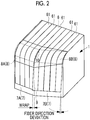
Fig. 2 is a perspective view illustrating the mold for prepreg lamination according to the first embodiment of the invention, and illustrates a state where prepreg tapes are compressed on a surface. -
Fig. 3 is a perspective view illustrating a mold for prepreg lamination according to a second embodiment of the invention. -
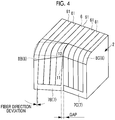
Fig. 4 is a perspective view illustrating the mold for prepreg lamination according to the second embodiment of the invention, and illustrates a state where the prepreg tapes are compressed on the surface. -
Fig. 5 is a perspective view illustrating a mold for prepreg lamination according to a third embodiment of the invention. -
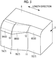
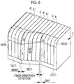
Fig. 6 is a perspective view illustrating the mold for prepreg lamination according to the third embodiment of the invention, and illustrates a state where the prepreg tapes are compressed on the surface. -
Fig. 7 is a perspective view illustrating a first example of a mold for prepreg lamination according to a fourth embodiment of the invention. -
Fig. 8 is a perspective view illustrating a second example of the mold for prepreg lamination according to the fourth embodiment of the invention. -
Fig. 9 is a plan view illustrating the second example of the mold for prepreg lamination according to the fourth embodiment of the invention. -
Fig. 10 is a perspective view illustrating a mold for prepreg lamination in the related art. -
Fig. 11 is a perspective view illustrating the mold for prepreg lamination in the related art, and illustrates a state where the prepreg tapes are compressed on the surface. -
Fig. 12 is a perspective view illustrating the mold for prepreg lamination in the related art. -
Fig. 13 is a plan view illustrating the mold for prepreg lamination in the related art. - Hereinafter, embodiments of the invention will be described with reference to the drawings.
- Hereinafter, a mold for
prepreg lamination 1 according to a first embodiment of the invention will be described usingFigs. 1 and2 . - The mold for prepreg lamination 1 (hereinafter, referred to as a "
mold 1") according to the embodiment is used in a case of laminating the prepreg, by a laminating device such as an automated fiber laminating device (AFP) or an automated tape laminating device (ATL). The laminating device such as the AFP feeds tape-shaped prepreg (hereinafter, referred to as "prepreg tape") 61 having a predetermined width to the surface of the mold for lamination. At this time, theprepreg tape 61 is continuously attached in one direction on the surface of themold 1. The prepreg laminated in a plurality of layers is cured to be formed as a molded article. - When a composite material molded article has a shape in which two plate materials are combined at a predetermined angle (for example, 90°) (for example, when a part of the cross section has an L shape), the
mold 1 for forming a molded article has afirst surface 6 and asecond surface 7. In a case where theprepreg tape 61 is attached to such amold 1, theprepreg tape 61 is attached from thefirst surface 6 toward the second surface 7 (or from thesecond surface 7 toward the first surface 6) of themold 1 as illustrated inFig. 2 . Further, theprepreg tape 61 fed from the laminating device is attached while being compressed by the compaction roller. A plurality ofprepreg tapes 61 are disposed side by side along a length direction of themold 1. - The
mold 1 includes thefirst surface 6 having only a flat surface along the length direction, thesecond surface 7 which has a flat surface along the length direction and is disposed at a predetermined angle with respect to thefirst surface 6, and athird surface 8 formed between thefirst surface 6 and thesecond surface 7. Here, the molded article formed by themold 1 is a long material that is long in one direction. Further, in a case where thefirst surface 6 is dispose to face an upward direction and thesecond surface 7 is disposed to face a lateral direction, thefirst surface 6 becomes an upper surface and thesecond surface 7 becomes a side surface. - The
third surface 8 is a fillet surface, and is a curved surface in which the cross-sectional shape of the surface cut in a direction orthogonal to the length direction is an arc. Thethird surface 8 has one end side continuously connected to thefirst surface 6 and the other end side continuously connected to thesecond surface 7. The arc as the cross-sectional shape of thethird surface 8 may be a part of a perfect circle or may be a part of an ellipse. - In a range of the length direction in which the
first surface 6 only has the flat surface along the length direction, protruding firstbent parts second surface 7 and thethird surface 8. In thesecond surface 7, onesurface 7B is inclined with respect to theother surface 7A with the protruding firstbent part 9 as a boundary, and in thethird surface 8, onesurface 8B is inclined with respect to theother surface 8A with the protruding firstbent part 10 as a boundary. For example, the angle formed by the onesurface 7B and theother surface 7A and the angle formed by the onesurface 8B and theother surface 8A are greater than 180° and smaller than 270°. - The first
bent part 9 is a part where thesurface 7A and thesurface 7B are combined, and has a linear shape. The firstbent part 10 is a part where thesurface 8A and thesurface 8B are combined, and has a curved shape. - The diameter of the arc of the cross-sectional shape of the
surface 8B of thethird surface 8 is gradually reduced as the distance from the protruding firstbent part 10 is increased along the length direction. As illustrated inFig. 2 , in a case where theprepreg tape 61 is compressed from thefirst surface 6 toward the second surface 7 (or from thesecond surface 7 toward the first surface 6) of themold 1 by the laminating device, the length of the side end portion of thetape 61 attached on thesurface 8B of thethird surface 8 is shorter on a side far from the firstbent part 10 than a side close to the firstbent part 10. Therefore, as illustrated inFig. 2 , the attachment direction of thetape 61 in thesurfaces second surface 7 is less likely to be inclined with respect to the vertical direction as compared with a case where the arc of the cross-sectional shape of asurface 55B of afillet surface 55 has the same diameter along the length direction as illustrated inFig. 10 . Therefore, the direction deviation is reduced, and the overlapping (wrap) of the plurality oftapes 61 is reduced. - According to the embodiment, since the overlapping (wrap) of the plurality of
tapes 61 is reduced, after the prepregs are laminated, the unevenness of the lamination thickness is reduced. As a result, the strength of the cured molded article is less likely to be decreased, and irregularities occurring on the surface of the molded article are reduced. Further, unlike a case of using themold 50 in which the direction deviation of thetape 61 is large as illustrated inFig. 10 , it is not necessary to narrow the width of thetape 61 fed from the head of the laminating device or to reduce the number oftapes 61 to be fed. Therefore, since it is not necessary to reduce the width or the number oftapes 61 which can be compressed at the same time, the repetition of the compression process is not increased, and the time required for lamination can be prevented from being increased. - Hereinafter, a mold for
prepreg lamination 2 according to a second embodiment of the invention will be described usingFigs. 3 and4 . The detailed description of the configurations overlapping with those of the first embodiment is omitted. - As with the
mold 1 of the first embodiment, the mold for prepreg lamination 2 (hereinafter, referred as a "mold 2") according to the embodiment is used when a composite material molded article has a shape in which two plate materials are combined at a predetermined angle (for example, 90°) (for example, when a part of the cross section has an L shape), themold 2 for forming a molded article has thefirst surface 6, thesecond surface 7, and thethird surface 8. - In a range of the length direction in which the
first surface 6 only has the flat surface along the length direction, recessed secondbent parts second surface 7 and thethird surface 8. In thesecond surface 7, onesurface 7B is inclined with respect to theother surface 7C with the recessed secondbent part 11 as a boundary, and in thethird surface 8, onesurface 8B is inclined with respect to theother surface 8C with the recessed secondbent part 12 as a boundary. For example, the angle formed by the onesurface 7B and theother surface 7C and the angle formed by the onesurface 8B and theother surface 8C are greater than 90° and smaller than 180°. - The second
bent part 11 is a part where thesurface 7B and thesurface 7C are combined, and has a linear shape. The secondbent part 12 is a part where thesurface 8B and thesurface 8C are combined, and has a curved shape. - The diameter of the arc of the cross-sectional shape of the
surface 8B of thethird surface 8 is gradually increased as the distance from the recessed secondbent part 12 is increased along the length direction. As illustrated inFig. 4 , in a case where theprepreg tape 61 is compressed from thefirst surface 6 toward the second surface 7 (or from thesecond surface 7 toward the first surface 6) of themold 2 by the laminating device, the length of the side end portion of thetape 61 attached on thesurface 8B of thethird surface 8 is longer on a side far from the secondbent part 12 than a side close to the secondbent part 12. Therefore, as illustrated inFig. 4 , the attachment direction of thetape 61 in thesurface 7B of thesecond surface 7 is less likely to be inclined with respect to the vertical direction as compared with a case where the arc of the cross-sectional shape of thesurface 55B of thefillet surface 55 has the same diameter along the length direction as illustrated inFig. 10 . Therefore, the direction deviation is reduced, and the gap generated between the plurality oftapes 61 is reduced. - According to the embodiment, since the gap generated between the plurality of
tapes 61 is reduced, after the prepregs are laminated, the strength of the cured molded article is less likely to be decreased and the irregularities occurring on the surface of the molded article are reduced. Further, unlike a case of using themold 50 in which the direction deviation of thetape 61 is large, it is not necessary to narrow the width of thetape 61 fed from the head of the laminating device or to reduce the number oftapes 61 to be fed. Therefore, since it is not necessary to reduce the width or the number oftapes 61 which can be compressed at the same time, the repetition of the compression process is not increased, and the time required for lamination can be prevented from being increased. - Hereinafter, a mold for
prepreg lamination 3 according to a third embodiment of the invention will be described usingFigs. 5 and6 . The detailed description of the configurations overlapping with those of the first and second embodiments is omitted. - As with the
molds mold 3") according to the embodiment is used when a composite material molded article has a shape in which two plate materials are combined at a predetermined angle (for example, 90°) (for example, when a part of the cross section has an L shape), themold 3 for forming a molded article has thefirst surface 6, thesecond surface 7, and thethird surface 8. - In the
molds bent parts bent parts second surface 7 and thethird surface 8 has been described, but in this embodiment, both the protruding firstbent parts bent parts mold 3. - In the
mold 3 according to the embodiment, in a range of the length direction in which thefirst surface 6 only has the flat surface along the length direction, the protruding firstbent parts second surface 7 and thethird surface 8, and the recessed secondbent parts second surface 7 and thethird surface 8. In a case where the prepreg is laminated on themold 3 having the firstbent parts bent parts second surface 7 is gradually changed (becomes thick or thin) along the length direction. Further, in a case where the prepreg is laminated on themold 3 having the firstbent parts bent parts - The diameter of the arc of the cross-sectional shape of the
surface 8B of thethird surface 8 is gradually reduced as the distance from the protruding firstbent part 10 is increased along the length direction, and is gradually increased as the distance from the recessed secondbent part 12 is increased along the length direction. As illustrated inFig. 6 , in a case where theprepreg tape 61 is compressed from thefirst surface 6 toward the second surface 7 (or from thesecond surface 7 toward the first surface 6) of themold 3 by the laminating device, the length of the side end portion of thetape 61 attached on thesurface 8B of thethird surface 8 is shorter on a side far from the firstbent part 10 than a side close to the firstbent part 10, and the length of the side end portion of thetape 61 attached on thesurface 8B of thethird surface 8 is longer on a side far from the secondbent part 12 than a side close to the secondbent part 12. On the other hand, as illustrated inFig. 10 , when the arc of the cross-sectional shape of thesurface 55B of thefillet surface 55 has the same diameter along the length direction, the length of the side end portion of thetape 61 attached on thesurface 55B of thefillet surface 55 is substantially the same on a side close to the firstbent part 10 and a side far from the firstbent part 10. Therefore, the deviation of the attachment direction of thetape 61 is large in theside surface 52. - In contrast, in this embodiment, as illustrated in
Fig. 6 , the attachment direction of thetape 61 in thesurfaces second surface 7 is less likely to be inclined with respect to the vertical direction as compared with a case where the arc of the cross-sectional shape of thesurface 55B of thefillet surface 55 has the same diameter along the length direction as illustrated inFig. 10 . Therefore, the direction deviation is reduced, the overlapping (wrap) of the plurality oftapes 61 is reduced, and the gap generated between the plurality oftapes 61 is reduced. - According to the embodiment, since the overlapping (wrap) of the plurality of
tapes 61 is reduced and the gap generated between the plurality oftapes 61 is reduced, after the prepregs are laminated, the unevenness of the lamination thickness is reduced. As a result, the strength of the cured molded article is less likely to be decreased, and irregularities occurring on the surface of the molded article are reduced. Further, unlike the case of using themold 50 in which the direction deviation of thetape 61 is large, it is not necessary to narrow the width of thetape 61 fed from the head of the laminating device or to reduce the number oftapes 61 to be fed. Therefore, since it is not necessary to reduce thetapes 61 which can be compressed at the same time, the repetition of the compression process is not increased, and the time required for lamination can be prevented from being increased. - Hereinafter, a mold for
prepreg lamination 4 and a mold for prepreg lamination 5 according to a fourth embodiment of the invention will be described usingFigs. 7 to 9 . - In the first to third embodiments described above, the first
bent part 9 or the secondbent part 11 is a portion where both theflat surfaces flat surfaces bent part 10 or the secondbent part 12 is a portion where both thecurved surfaces curved surfaces - In contrast, in this embodiment, as illustrated in
Figs. 7 to 9 , in the firstbent part 9 or the secondbent part 11, a protrudingcurved portion 13 or a recessedcurved portion 15 is formed such that a straight line is not formed at the top of the protruding portion or the bottom of the recessed portion. Further, in the firstbent part 10 or the secondbent part 12, a protrudingcurved portion 14 or a recessedcurved portion 16 is formed such that a curved line is not formed at the top of the protruding portion or the bottom of the recessed portion. - The first
bent part 9 is connected to the onesurface 7A and theother surface 7B through the protrudingcurved portion 13, and the firstbent part 10 is connected to the onesurface 8A and theother surface 8B through the protrudingcurved portion 14. The secondbent part 11 is connected to the onesurface 7C and theother surface 7B through the recessedcurved portion 15, and the secondbent part 12 is connected to the onesurface 8C and theother surface 8B through the recessedcurved portion 16. - The protruding
curved portions curved portions surface 7A and theother surface 7B are smoothly connected through the protrudingcurved portion 13, and the onesurface 8A and theother surface 8B are smoothly connected through the protrudingcurved portion 14. The onesurface 7C and theother surface 7B are smoothly connected through the recessedcurved portion 15, and the onesurface 8C and theother surface 8B are smoothly connected through the recessedcurved portion 16. The arc as the cross-sectional shape of the protrudingcurved portions curved portions - As in the first to third embodiments, in a case where the top of the first
bent parts bent parts mold compaction roller 70 to come into contact with the surface of themold bent parts bent parts tape 61 by thecompaction roller 70 tends to be insufficient. - On the other hand, according to this embodiment, an angle formed by the tangent planes of the
curved portions bent parts other surfaces bent parts curved portions curved portions other surfaces bent parts curved portions bent parts curved portions curved portions compaction roller 70 to come into contact with the surface of themold 4 or 5 on both sides of the firstbent parts bent parts tape 61 by thecompaction roller 70 on both sides of the firstbent parts bent parts -
- 1, 2, 3, 4, 5:
- mold for prepreg lamination
- 6:
- first surface
- 7:
- second surface
- 8:
- third surface
- 9, 10:
- first bent part
- 11, 12:
- second bent part
- 13, 14, 15, 16:
- curved portion
- 50:
- mold
- 51:
- upper surface
- 52:
- side surface
- 53, 54:
- bent part
- 55:
- fillet surface
- 60:
- molded article
- 61:
- prepreg tape
- 70:
- compaction roller
Claims (6)
- A mold for prepreg lamination comprising:a first surface having only a flat surface along one direction;a second surface which has a flat surface along the one direction and is disposed at a predetermined angle with respect to the first surface; anda third surface in which a cross-sectional shape of a surface cut in a direction orthogonal to the one direction is an arc, and which has one end side connected to the first surface and the other end side connected to the second surface,wherein, in the second surface and the third surface, a protruding first bent part is formed, and one surface is inclined with respect to the other surface with the first bent part as a boundary, anda diameter of the arc of the other surface of the third surface is gradually reduced as a distance from the first bent part is increased along the one direction.
- A mold for prepreg lamination comprising:a first surface having only a flat surface along one direction;a second surface which has a flat surface along the one direction and is disposed at a predetermined angle with respect to the first surface; anda third surface in which a cross-sectional shape of a surface cut in a direction orthogonal to the one direction is an arc, and which has one end side connected to the first surface and the other end side connected to the second surface,wherein, in the second surface and the third surface, a recessed second bent part is formed, and one surface is inclined with respect to the other surface with the second bent part as a boundary, anda diameter of the arc of the other surface of the third surface is gradually increased as a distance from the second bent part is increased along the one direction.
- The mold for prepreg lamination according to claim 1 or 2,
wherein the first bent part or the second bent part has a curved portion having a curved shape, and is connected to the one surface and the other surface through the curved portion. - A mold for prepreg lamination comprising:a first surface having only a flat surface along one direction;a second surface which has a flat surface along the one direction and is disposed at a predetermined angle with respect to the first surface; anda third surface in which a cross-sectional shape of a surface cut in a direction orthogonal to the one direction is an arc, and which has one end side connected to the first surface and the other end side connected to the second surface,wherein, in the second surface and the third surface, a protruding or recessed bent part is formed, and one surface is inclined with respect to the other surface with the bent part as a boundary, andthe bent part has a curved portion having a curved shape, and is connected to the one surface and the other surface through the curved portion.
- A prepreg lamination method comprising:a step of attaching a tape-shaped prepreg tape to the first surface or the second surface of the mold for prepreg lamination according to claim 1 or 2, and then attaching the prepreg tape to the third surface; anda step of attaching the prepreg tape to the second surface or the first surface after attaching the prepreg tape to the third surface.
- A prepreg lamination method comprising:
a step of attaching a tape-shaped prepreg tape to the curved portion and the one surface or the other surface of the mold for prepreg lamination according to claim 3 or 4, and compressing the prepreg tape using a compaction roller.
Applications Claiming Priority (2)
| Application Number | Priority Date | Filing Date | Title |
|---|---|---|---|
| JP2018114466A JP7034846B2 (en) | 2018-06-15 | 2018-06-15 | Mold for prepreg laminating and prepreg laminating method |
| PCT/JP2019/017120 WO2019239724A1 (en) | 2018-06-15 | 2019-04-23 | Mold for prepreg lamination and prepreg lamination method |
Publications (2)
| Publication Number | Publication Date |
|---|---|
| EP3763501A1 true EP3763501A1 (en) | 2021-01-13 |
| EP3763501A4 EP3763501A4 (en) | 2021-07-14 |
Family
ID=68843184
Family Applications (1)
| Application Number | Title | Priority Date | Filing Date |
|---|---|---|---|
| EP19820249.1A Withdrawn EP3763501A4 (en) | 2018-06-15 | 2019-04-23 | Mold for prepreg lamination and prepreg lamination method |
Country Status (5)
| Country | Link |
|---|---|
| US (1) | US11760074B2 (en) |
| EP (1) | EP3763501A4 (en) |
| JP (1) | JP7034846B2 (en) |
| CN (1) | CN111989200A (en) |
| WO (1) | WO2019239724A1 (en) |
Families Citing this family (3)
| Publication number | Priority date | Publication date | Assignee | Title |
|---|---|---|---|---|
| CN112078148B (en) * | 2020-08-18 | 2022-03-04 | 武汉大学 | Automatic composite material laying device applied to curved surface |
| KR102309869B1 (en) * | 2020-09-15 | 2021-10-07 | 주식회사 디아이씨 | Manufacturing method of back cover for mobile communication device and mold used therein |
| CN116494558B (en) * | 2023-03-22 | 2025-11-18 | 中建材(上海)航空技术有限公司 | Molding method with curvature structure |
Family Cites Families (20)
| Publication number | Priority date | Publication date | Assignee | Title |
|---|---|---|---|---|
| JPH0671742A (en) | 1992-08-27 | 1994-03-15 | Toray Ind Inc | Method of molding drape |
| JP2001038752A (en) * | 1999-07-30 | 2001-02-13 | Fuji Heavy Ind Ltd | Apparatus and method for forming composite curved panel |
| US6799619B2 (en) * | 2002-02-06 | 2004-10-05 | The Boeing Company | Composite material collation machine and associated method for high rate collation of composite materials |
| JP5332225B2 (en) * | 2007-02-22 | 2013-11-06 | 東レ株式会社 | Manufacturing method of fiber reinforced composite material |
| CN100461192C (en) * | 2007-06-22 | 2009-02-11 | 北京航空航天大学 | SIMULATION METHOD OF RESIN FLOW AND LAMINATE DEFORMATION IN L-SHAPED LAMINATES IN THERMAL PRESSURE MOLDING |
| GB0712552D0 (en) | 2007-06-29 | 2007-08-08 | Airbus Uk Ltd | Elongate composite structural members and improvements therein |
| GB0712549D0 (en) * | 2007-06-29 | 2007-08-08 | Airbus Uk Ltd | Improvements in elongate composite structural members |
| US20100284810A1 (en) * | 2009-05-07 | 2010-11-11 | General Electric Company | Process for inhibiting delamination in a bend of a continuous fiber-reinforced composite article |
| US8790566B2 (en) * | 2009-06-01 | 2014-07-29 | Mitsubishi Heavy Industries, Ltd. | Manufacturing method of composite material member and prepreg sheet laminate |
| JP2011179587A (en) * | 2010-03-01 | 2011-09-15 | Toyota Motor Corp | Pressure vessel |
| JP5260593B2 (en) | 2010-05-06 | 2013-08-14 | 三菱重工業株式会社 | Mold and mold manufacturing method |
| US8795567B2 (en) * | 2010-09-23 | 2014-08-05 | The Boeing Company | Method for fabricating highly contoured composite stiffeners with reduced wrinkling |
| CN104484516A (en) * | 2014-12-04 | 2015-04-01 | 江苏恒神纤维材料有限公司 | Method of laying prepreg by aid of trajectory planning software |
| CN205310853U (en) * | 2015-11-16 | 2016-06-15 | 上海航天设备制造总厂 | Device is put to automatic shop of curved surface |
| CN105818401A (en) * | 2016-03-25 | 2016-08-03 | 哈尔滨飞机工业集团有限责任公司 | Method for controlling jointing gap of prepreg cloth |
| US10105940B2 (en) * | 2016-04-18 | 2018-10-23 | The Boeing Company | Formation of composite laminates having one or more divergent flanges |
| CN106404920A (en) * | 2016-06-15 | 2017-02-15 | 中国航空工业集团公司北京航空材料研究院 | Reference test block for ultrasonic detection of composite-material R corner structure |
| EP3323602A1 (en) * | 2016-11-22 | 2018-05-23 | Airbus Operations GmbH | Method and tool system for manufacturing a multilayer fibre structure |
| CN107234817B (en) * | 2017-05-19 | 2019-07-26 | 北京航空航天大学 | A precise and real-time controllable wire laying compaction device |
| CN107953576B (en) * | 2017-12-14 | 2020-06-30 | 中国航空工业集团公司基础技术研究院 | RTM (resin transfer molding) forming die and method suitable for composite angle material |
-
2018
- 2018-06-15 JP JP2018114466A patent/JP7034846B2/en active Active
-
2019
- 2019-04-23 CN CN201980026049.5A patent/CN111989200A/en active Pending
- 2019-04-23 WO PCT/JP2019/017120 patent/WO2019239724A1/en not_active Ceased
- 2019-04-23 US US17/045,249 patent/US11760074B2/en active Active
- 2019-04-23 EP EP19820249.1A patent/EP3763501A4/en not_active Withdrawn
Also Published As
| Publication number | Publication date |
|---|---|
| JP2019217639A (en) | 2019-12-26 |
| EP3763501A4 (en) | 2021-07-14 |
| US11760074B2 (en) | 2023-09-19 |
| JP7034846B2 (en) | 2022-03-14 |
| WO2019239724A1 (en) | 2019-12-19 |
| CN111989200A (en) | 2020-11-24 |
| US20210170637A1 (en) | 2021-06-10 |
Similar Documents
| Publication | Publication Date | Title |
|---|---|---|
| CN107878726B (en) | Advanced Variable Radius Laminated Composite Radius Filler | |
| US11760074B2 (en) | Mold for prepreg lamination and prepreg lamination method | |
| US9308982B2 (en) | Composite joint protection | |
| EP2433781B1 (en) | Method and apparatus for fabricating highly contoured composite stiffeners with reduced wrinkling | |
| EP3536488B1 (en) | Preform figuring method and composite material shaping method | |
| US7722944B2 (en) | Piece made of composite material with areas of different thickness | |
| US20120282430A1 (en) | Composite material part with large variation in thickness | |
| EP3838569B1 (en) | Method for forming fibre composite preforms | |
| US20140023830A1 (en) | Method of manufacturing a structure | |
| JP5374866B2 (en) | Laminate compression molding apparatus, preform manufacturing method, and prepreg molded body manufacturing method | |
| US20210276300A1 (en) | Composite material and method of shaping composite material | |
| EP2965890B1 (en) | Roll forming composite components | |
| CN107825727A (en) | The forming method and shaped device and wallboard of preforming stringer L-shaped part and wallboard | |
| CN112440491A (en) | Method of manufacturing composite structures using a co-curing process | |
| US11577816B2 (en) | Composite laminate for an airframe lifting surface and method for manufacturing thereof | |
| CN106393515A (en) | Tool used for integral co-curing forming of composite flat empennage twin-beam box section | |
| CN206085432U (en) | Whole co -curing of two roof beam box sections of straight fin of combined material frock for shaping | |
| US12162228B2 (en) | Composite structures | |
| US11993030B2 (en) | Composite material component shaping method and charge | |
| EP4119334A1 (en) | Composite material structure and manufacturing method of composite material structure | |
| EP4035863A1 (en) | Hybrid molded body, molding apparatus, and molding method | |
| EP4656364A1 (en) | Composite radius fillers, assemblies including composite radius fillers, and systems and methods of forming the same | |
| EP3744511B1 (en) | Composite forming station |
Legal Events
| Date | Code | Title | Description |
|---|---|---|---|
| STAA | Information on the status of an ep patent application or granted ep patent |
Free format text: STATUS: THE INTERNATIONAL PUBLICATION HAS BEEN MADE |
|
| PUAI | Public reference made under article 153(3) epc to a published international application that has entered the european phase |
Free format text: ORIGINAL CODE: 0009012 |
|
| STAA | Information on the status of an ep patent application or granted ep patent |
Free format text: STATUS: REQUEST FOR EXAMINATION WAS MADE |
|
| 17P | Request for examination filed |
Effective date: 20201007 |
|
| AK | Designated contracting states |
Kind code of ref document: A1 Designated state(s): AL AT BE BG CH CY CZ DE DK EE ES FI FR GB GR HR HU IE IS IT LI LT LU LV MC MK MT NL NO PL PT RO RS SE SI SK SM TR |
|
| AX | Request for extension of the european patent |
Extension state: BA ME |
|
| A4 | Supplementary search report drawn up and despatched |
Effective date: 20210616 |
|
| RIC1 | Information provided on ipc code assigned before grant |
Ipc: B32B 38/08 20060101ALI20210610BHEP Ipc: B32B 37/00 20060101ALI20210610BHEP Ipc: B29K 105/08 20060101ALI20210610BHEP Ipc: B29C 70/46 20060101ALI20210610BHEP Ipc: B29C 70/38 20060101ALI20210610BHEP Ipc: B29C 70/16 20060101ALI20210610BHEP Ipc: B29C 43/36 20060101ALI20210610BHEP Ipc: B29C 43/34 20060101ALI20210610BHEP Ipc: B29C 33/38 20060101AFI20210610BHEP |
|
| DAV | Request for validation of the european patent (deleted) | ||
| DAX | Request for extension of the european patent (deleted) | ||
| STAA | Information on the status of an ep patent application or granted ep patent |
Free format text: STATUS: THE APPLICATION HAS BEEN WITHDRAWN |
|
| 18W | Application withdrawn |
Effective date: 20220222 |