JP5374866B2 - Laminate compression molding apparatus, preform manufacturing method, and prepreg molded body manufacturing method - Google Patents
Laminate compression molding apparatus, preform manufacturing method, and prepreg molded body manufacturing method Download PDFInfo
- Publication number
- JP5374866B2 JP5374866B2 JP2007326846A JP2007326846A JP5374866B2 JP 5374866 B2 JP5374866 B2 JP 5374866B2 JP 2007326846 A JP2007326846 A JP 2007326846A JP 2007326846 A JP2007326846 A JP 2007326846A JP 5374866 B2 JP5374866 B2 JP 5374866B2
- Authority
- JP
- Japan
- Prior art keywords
- laminate
- thickness
- mold
- adjusting member
- gap adjusting
- Prior art date
- Legal status (The legal status is an assumption and is not a legal conclusion. Google has not performed a legal analysis and makes no representation as to the accuracy of the status listed.)
- Expired - Fee Related
Links
Images


Description
本発明は、積層体の圧縮賦形装置およびプリフォームの製造方法およびプリプレグ成形体の製造方法に関する。さらに詳しくは、繊維強化複合材料(以下、FRPという)を成形する際に用いるプリフォームにおいて長手方向に積層枚数が変化しても、同一の金型で賦形するための積層体の圧縮賦形装置およびプリフォームの製造方法およびプリプレグ成形体の製造方法に関する。 The present invention relates to a compression molding apparatus for a laminate, a method for manufacturing a preform, and a method for manufacturing a prepreg molded body. More specifically, even if the number of laminated layers changes in the longitudinal direction in a preform used when molding a fiber reinforced composite material (hereinafter referred to as FRP), compression molding of the laminate for shaping with the same mold The present invention relates to an apparatus, a preform manufacturing method, and a prepreg molded body manufacturing method.
炭素繊維やガラス繊維、アラミド繊維を強化繊維として用いたFRPは、軽量でかつ高い耐久性を有するものであることから、自動車や航空機などを構成する各種の構成部材として理想的な材料である。このFRPの成形方法としては、強化繊維基材を複数枚積層し、金型で挟み加圧することにより賦形し、所定の形状に成形する方法が知られている。 FRP using carbon fiber, glass fiber, or aramid fiber as a reinforcing fiber is lightweight and highly durable, and is therefore an ideal material for various components constituting automobiles and aircraft. As a method for molding this FRP, a method is known in which a plurality of reinforcing fiber base materials are stacked, shaped by sandwiching and pressing with a mold, and molded into a predetermined shape.
強化繊維基材としては、例えば強化繊維をシート状に複数本引き揃え、エポキシ樹脂等のマトリクス樹脂を含浸させ、シート状に成形したプリプレグシートが用いられている。このプリプレグシートを複数枚積層し、金型内で加圧・加熱して硬化させ成形する。 As the reinforcing fiber base, for example, a prepreg sheet formed by arranging a plurality of reinforcing fibers in a sheet shape and impregnating a matrix resin such as an epoxy resin into a sheet shape is used. A plurality of the prepreg sheets are stacked and cured by pressurization and heating in a mold.
また、マトリクス樹脂が含浸されていない、ドライな強化繊維基材を用いたFRPの成形も行われている。これはResin Transfer Molding(以下、RTMという)成形方法や真空RTM成形方法などと呼ばれる成形方法であり、層間接着樹脂が付加された強化繊維基材を複数枚積層し、金型で賦形したプリフォームと呼ばれる成形品を製作した後、このプリフォームに低粘度の液状マトリクス樹脂を注入し、硬化させるものである。 In addition, FRP is molded using a dry reinforcing fiber base material that is not impregnated with a matrix resin. This is a molding method called a Resin Transfer Molding (hereinafter referred to as RTM) molding method or a vacuum RTM molding method, in which a plurality of reinforcing fiber substrates to which an interlaminar adhesive resin has been added are laminated and shaped with a mold. After a molded product called a reform is manufactured, a low-viscosity liquid matrix resin is injected into the preform and cured.
なかでも、I型やH型の断面形状を持つ梁部材を製造する装置が知られている(例えば、特許文献1参照)。これは積層体を所定の断面形状に金型にて賦形した後、金型を開き積層体を所定量移動させ、再度賦形するということを繰り返し、長尺の成形品を成形する装置である。このような装置を用いることで、長手方向に一様な断面形状を持つ梁部材の成形を、その梁部材の全長分の大型の金型を用いることなく、小さな金型にて製造することができる。 Among them, an apparatus for manufacturing a beam member having an I-shaped or H-shaped cross-sectional shape is known (see, for example, Patent Document 1). This is an apparatus for molding a long molded product by repeatedly shaping the laminate to a predetermined cross-sectional shape with a mold, opening the mold, moving the laminate by a predetermined amount, and shaping again. is there. By using such an apparatus, it is possible to manufacture a beam member having a uniform cross-sectional shape in the longitudinal direction with a small mold without using a large mold for the entire length of the beam member. it can.
しかしながら、例えば片持ちの構造物を考えた場合、一般的にそれを支える梁部材は根元にいくほど剛性が高くなることが求められる。そのため、長尺の積層体成形品では積層枚数(積層体成形品の厚み)を増すことでこれに対応している。一方、上記従来技術は、一定形状・一定厚みの断面にて順次成形するものであるため、このような成形品の厚み変化には対応できなかった。
本発明の目的は、前記した従来技術の問題点を解決しようとするものであり、積層枚数が変化しても、同一の金型で賦形するための積層体の圧縮賦形装置およびプリフォームの製造方法およびプリプレグ成形体の製造方法を提供することにある。 SUMMARY OF THE INVENTION An object of the present invention is to solve the above-mentioned problems of the prior art, and even if the number of layers is changed, a compression molding apparatus and a preform for a laminate for forming with the same mold It is providing the manufacturing method of this, and the manufacturing method of a prepreg molded object.
上記課題を解決するために、本発明は、以下の手段を採用するものである。すなわち、
(1)相対する金型間における金型賦形面の間隔を調整するスキマ調整手段を有し、前記スキマ調整手段が長手方向に段階的に厚みの変化する帯状を成しているシート状のスキマ調整部材と前記スキマ調整部材を積層体と金型賦形面の間に配置する挿入手段とを有するとともに、前記積層体が強化繊維および結着性物質を含むことを特徴とする積層体の圧縮賦形装置。
In order to solve the above-described problems, the present invention employs the following means. That is,
(1) A sheet-like sheet having a gap adjusting means for adjusting the distance between the mold forming surfaces between the opposite molds, the gap adjusting means having a strip shape whose thickness changes stepwise in the longitudinal direction . A laminate having a gap adjusting member and an insertion means for disposing the gap adjusting member between the laminate and the mold shaping surface, and the laminate includes reinforcing fibers and a binding substance. Compression shaping device.
(2)前記スキマ調整部材を搬送する、巻出ボビンと巻取ボビンを備えた搬送手段を有しており、金型を挟み上流側に巻出ボビン、下流側に巻取ボビンが配置されていることを特徴とする前記(1)に記載の積層体の圧縮賦形装置。 ( 2 ) It has a conveying means having an unwinding bobbin and a winding bobbin for conveying the clearance adjusting member, and an unwinding bobbin is disposed upstream and a winding bobbin is disposed downstream. The compression molding apparatus for a laminate according to ( 1 ) above, wherein
(3)積層体の厚みのプロファイルを記録する厚み記録手段と、前記搬送手段による前記積層体の搬送量を記録する移動量記録手段と、前記厚み記録手段と前記移動量記録手段に記録された値に基づき前記スキマ調整部材の搬送手段によるスキマ調整部材の搬送量を演算する演算手段を有することを特徴とする前記(2)に記載の積層体の圧縮賦形装置。 ( 3 ) recorded on the thickness recording means for recording the thickness profile of the laminate, the movement amount recording means for recording the conveyance amount of the laminate by the conveyance means, the thickness recording means and the movement amount recording means The compression molding apparatus for a laminate according to ( 2 ), further comprising a calculation unit that calculates a conveyance amount of the clearance adjustment member by the conveyance unit of the clearance adjustment member based on the value.
(4)前記金型が発熱体と温度調節機構を有する加熱手段と、加圧機構と面圧検出機構を有する加圧手段とを有することを特徴とする前記(1)から(3)のいずれかに記載の積層体の圧縮賦形装置。
( 4 ) Any one of (1) to ( 3 ), wherein the mold includes a heating unit having a heating element and a temperature adjusting mechanism, and a pressing unit having a pressurizing mechanism and a surface pressure detecting mechanism. A compression molding apparatus for a laminate according to
(5)金型賦形面に曲面が含まれていることを特徴とする前記(1)から(4)のいずれかに記載の積層体の圧縮賦形装置。 ( 5 ) The compression molding apparatus for a laminate according to any one of (1) to ( 4 ), wherein the mold shaping surface includes a curved surface.
(6)型締めと型開きを交互に繰り返す手段と、この開閉動作にあわせて積層体を搬送する搬送手段とを有することを特徴とする前記(1)から(5)のいずれかに記載の積層体の圧縮賦形装置。 ( 6 ) The apparatus according to any one of (1) to ( 5 ), characterized in that it includes means for alternately repeating mold clamping and mold opening, and conveying means for conveying the laminate in accordance with the opening and closing operation. Compression molding equipment for laminates.
(7)前記スキマ調整部材は、1枚または複数枚のシート状部材からなることを特徴とする前記(1)から(6)のいずれかに記載の積層体の圧縮賦形装置。 ( 7 ) The compression molding apparatus for a laminated body according to any one of (1) to ( 6 ), wherein the clearance adjusting member includes one or a plurality of sheet-like members.
(8)前記シート状部材の積層枚数を増減することにより、前記スキマ調整部材の厚みを段階的に変化させることを特徴とする前記(7)に記載の積層体の圧縮賦形装置。 ( 8 ) The compression molding apparatus for a laminate according to ( 7 ), wherein the thickness of the gap adjusting member is changed stepwise by increasing / decreasing the number of laminated sheet-like members.
(9)強化繊維と結着性物質を含む積層体を、長手方向で段階的に厚みの異なる帯状体であるシート状のスキマ調整部材と一体に賦形し、かつ、前記積層体の厚みの増減に応じ前記スキマ調整部材の厚みを調整し、対応する厚みの部分が賦形面にくるように前記スキマ調整部材を搬送し賦形することを特徴とするプリフォームの製造方法。 ( 9 ) A laminate including reinforcing fibers and a binding substance is formed integrally with a sheet-like gap adjusting member that is a strip- like body having a thickness that is stepwise different in the longitudinal direction , and the thickness of the laminate is A method for manufacturing a preform , wherein the thickness of the clearance adjustment member is adjusted according to an increase or decrease, and the clearance adjustment member is conveyed and shaped so that a corresponding thickness portion is on the shaping surface .
(10)金型賦形面に前記スキマ調整部材を取り付けておき、前記積層体を金型内に搬送し、圧縮賦形するプリフォームの製造方法であって、かつ、前記積層体の厚みの増減に応じ前記スキマ調整部材を入れ替えることを特徴とする前記(9)に記載のプリフォームの製造方法。 (1 0 ) A preform manufacturing method in which the gap adjusting member is attached to a mold shaping surface, the laminate is conveyed into a mold, and compression-molded, and the thickness of the laminate The preform manufacturing method according to ( 9 ), wherein the clearance adjustment member is replaced in accordance with an increase or decrease of.
(11)積層体の厚みの増減に応じた厚みの前記スキマ調整部材を前記積層体の厚みごとにそれぞれ貼り付け、前記積層体と前記スキマ調整部材を一体に金型内に搬送し、圧縮賦形することを特徴とする前記(9)に記載のプリフォームの製造方法。 (1 1 ) The clearance adjustment member having a thickness corresponding to the increase / decrease in the thickness of the laminate is attached to each thickness of the laminate, and the laminate and the clearance adjustment member are integrally conveyed into a mold and compressed. The method for producing a preform according to ( 9 ), wherein the preform is shaped.
(12)前記積層体を、屈曲部を有する形状に賦形することを特徴とする前記(9)から(11)のいずれかに記載のプリフォームの製造方法。 (1 2 ) The preform manufacturing method according to any one of ( 9 ) to (1 1 ), wherein the laminate is shaped into a shape having a bent portion.
(13)帯状の積層体を金型内に間欠的に搬送し、順次賦形するプリフォームの製造方法であって、かつ、前記積層体の厚みが長手方向で異なっていることを特徴とする前記(9)から(12)のいずれかに記載のプリフォームの製造方法。 (1 3 ) A preform manufacturing method in which a belt-shaped laminate is intermittently conveyed into a mold and shaped sequentially, and the thickness of the laminate is different in the longitudinal direction. The method for producing a preform according to any one of ( 9 ) to (1 2 ).
(14)前記スキマ調整部材が1枚または複数枚のシート状部材からなり、前記シート状部材の積層枚数を増減させることにより前記スキマ調整部材の厚みを調整することを特徴とする前記(9)から(13)のいずれかに記載のプリフォームの製造方法。 (1 4) the said gap adjusting member is composed of one or a plurality of sheet-like member, and adjusting the thickness of the gap adjusting member by increasing or decreasing the number of laminated sheets of the sheet-like member (9 ) To (1 3 ).
(15)強化繊維と結着性物質を含む積層体を、長手方向で段階的に厚みの異なる帯状体であるシート状のスキマ調整部材と一体に賦形し、かつ、前記積層体の厚みの増減に応じ前記スキマ調整部材の厚みを調整し、対応する厚みの部分が賦形面にくるように前記スキマ調整部材を搬送し賦形することを特徴とするプリプレグ成形体の製造方法。 ( 15 ) A laminate including reinforcing fibers and a binding substance is formed integrally with a sheet-like gap adjusting member, which is a strip- like body having a thickness that varies stepwise in the longitudinal direction , and the thickness of the laminate. A method for producing a prepreg molded body, comprising adjusting the thickness of the gap adjusting member according to increase / decrease of the sheet and conveying and shaping the gap adjusting member so that a corresponding thickness portion is on the shaping surface .
(16)金型賦形面に前記スキマ調整部材を取り付けておき、前記積層体を金型内に搬送し、圧縮賦形するプリプレグ成形体の製造方法であって、かつ、前記積層体の厚みの増減に応じ前記スキマ調整部材を入れ替えることを特徴とする前記(15)に記載のプリプレグ成形体の製造方法。 ( 16 ) A manufacturing method of a prepreg molded body in which the gap adjusting member is attached to a mold shaping surface, the laminate is transported into a mold, and compression molded, and the laminate The method for producing a prepreg molded body according to ( 15 ), wherein the gap adjusting member is replaced according to an increase or decrease in thickness.
(17)積層体の厚みの増減に応じた厚みの前記スキマ調整部材を前記積層体の厚みごとにそれぞれ貼り付け、前記積層体と前記スキマ調整部材を一体に金型内に搬送し、圧縮賦形することを特徴とする前記(15)に記載のプリプレグ成形体の製造方法。
(1 7 ) The clearance adjustment member having a thickness corresponding to the increase / decrease in the thickness of the laminate is pasted for each thickness of the laminate, and the laminate and the clearance adjustment member are integrally conveyed into a mold and compressed. The method for producing a prepreg molded body according to the above ( 15 ), which is shaped.
(18)前記積層体を、屈曲部を有する形状に賦形する前記(15)から(17)のいずれかに記載のプリプレグ成形体の製造方法。 (18) The laminate, method for producing a prepreg molded article according to any one of the to be shaped into a shape having a bent portion (1 5) (1 7).
(19)帯状の積層体を金型内に間欠的に搬送し、順次賦形するプリプレグ成形体の製造方法であって、かつ、前記積層体の厚みが長手方向で異なっていることを特徴とする前記(15)から(18)のいずれかに記載のプリプレグ成形体の製造方法。 ( 19 ) A method for producing a prepreg molded body in which a belt-shaped laminated body is intermittently conveyed into a mold and sequentially shaped, and the thickness of the laminated body is different in the longitudinal direction. The method for producing a prepreg molded body according to any one of (1 5 ) to ( 18 ).
(20)前記スキマ調整部材が1枚または複数枚のシート状部材からなり、前記シート状部材の積層枚数を増減させることによりスキマ調整部材の厚みを調整することを特徴とする前記(15)から(19)のいずれかに記載のプリプレグ成形体の製造方法。
(2 0 ) The clearance adjustment member includes one or a plurality of sheet-like members, and the thickness of the clearance adjustment member is adjusted by increasing or decreasing the number of the sheet-like members stacked ( 15). ) To ( 19 ).
本発明の積層体の圧縮賦形装置およびプリフォームの製造方法およびプリプレグ成形体の製造方法によれば、賦形面の間隔が略均一な金型においても、賦形面と積層体のスキマをスキマ調整部材にて調整することにて、部分的に厚み(積層枚数)が異なる積層体でも、均一にかつ高い繊維体積含有率(=Vpf)にて賦形することができる。 According to the compression molding apparatus, the preform manufacturing method, and the prepreg molded body manufacturing method of the present invention, the clearance between the molding surface and the laminate can be reduced even in a mold having a substantially uniform spacing between the molding surfaces. By adjusting with the clearance adjusting member, even laminates having partially different thicknesses (number of stacked layers) can be shaped uniformly and with a high fiber volume content (= Vpf).
また、賦形面に曲面が含まれる場合、凸面側の賦形面に対し凹面側の賦形面の曲率は積層体の厚み分大きくなる。よって、積層体の厚みが異なると同一の金型では賦形できないが、スキマ調整部材を金型賦形面と積層体の間に充填することで厚みの異なる積層体を同一の金型で賦形できる。特に、金型の開閉にあわせて積層体を搬送し順次賦形することで、長手方向に略同一の断面形状を持つ積層体を賦形する際に、その長手方向に積層の厚みが異なっても、同一の金型にて賦形することが可能となる。 Moreover, when a curved surface is included in the shaping surface, the curvature of the shaping surface on the concave side is increased by the thickness of the laminate relative to the shaping surface on the convex surface side. Therefore, although the same mold cannot be formed if the thicknesses of the laminates are different, a laminate having different thicknesses can be formed with the same mold by filling the gap adjusting member between the mold shaping surface and the laminate. Can shape. In particular, when forming a laminate having substantially the same cross-sectional shape in the longitudinal direction by conveying and sequentially shaping the laminate according to the opening and closing of the mold, the thickness of the laminate differs in the longitudinal direction. Also, it is possible to shape with the same mold.
本発明で用いる「強化繊維」としては、炭素繊維やガラス繊維、アラミド繊維などが挙げられる。強化繊維はその形態として、織物、編み物、組み物、不織布、一方向に引き揃えられた強化繊維シートなど、シート状に成形されていることが好ましい。 Examples of the “reinforcing fiber” used in the present invention include carbon fiber, glass fiber, and aramid fiber. The reinforcing fiber is preferably formed into a sheet shape such as a woven fabric, a knitted fabric, a braided fabric, a nonwoven fabric, or a reinforcing fiber sheet aligned in one direction.
本発明で用いる「結着性物質」は、上記強化繊維に付着し、強化繊維同士を結着することで、強化繊維をシート状に形態安定化し「強化繊維シート」とするものであり、例えば、ポリオレフィン、スチレン系樹脂、ナイロン、ポリウレタンなどの熱可塑性樹脂、また、例えばエポキシ、フェノール、不飽和ポリエステルなどの熱硬化性樹脂などが挙げられる。 The “binding substance” used in the present invention is a material that adheres to the reinforcing fibers and binds the reinforcing fibers together to stabilize the form of the reinforcing fibers in a sheet form to form a “reinforcing fiber sheet”. And thermoplastic resins such as polyolefin, styrene resin, nylon, and polyurethane, and thermosetting resins such as epoxy, phenol, and unsaturated polyester.
上記「強化繊維シート」は、粉末状の結着性物質を強化繊維に散布し、部分的に結着させ形態安定化させた、いわゆるドライな強化繊維基材でもよいし、強化繊維全面に結着性物質を含浸し形態安定化させた、いわゆるプリプレグでもよい。 The “reinforcing fiber sheet” may be a so-called dry reinforcing fiber base material in which a powdery binding substance is dispersed on reinforcing fibers and partially bound to stabilize the shape, or may be bonded to the entire surface of the reinforcing fibers. A so-called prepreg impregnated with an adhesive material and stabilized in shape may also be used.
本発明における「積層体」は、上記「強化繊維シート」を複数枚積層したものである。 The “laminate” in the present invention is obtained by laminating a plurality of the above-mentioned “reinforced fiber sheets”.
本発明における「スキマ調整部材」は、金型の賦形面と積層体の間に介在し、積層体の厚みの変化により必要となる金型賦形面の変更に代え、積層体の厚み変化によって生じる金型賦形面と積層体とのスキマを埋め、金型による賦形の圧力を積層体に伝えるシート状物である。そのため、金型による賦形の際の圧力に耐え、かつ賦形後には積層体成形品と分離可能なことが求められる。その一例としては、離型紙やフッ素樹脂(例えば「テフロン(登録商標)」)シート、シリコーン樹脂シート、フッ素樹脂(例えば「テフロン(登録商標)」)やシリコーン樹脂を含浸したグラスシートなどが挙げられる。また、「スキマ調整部材」は単一のシート状部材で形成したもののほか、複数枚のシート状部材で形成したものも好適に用いることができる。 The “skimming adjusting member” in the present invention is interposed between the molding surface of the mold and the laminate, and changes in the thickness of the laminate instead of changing the mold shaping surface required due to the change in the thickness of the laminate. This is a sheet-like material that fills the gap between the mold shaping surface and the laminate produced by the above process and transmits the shaping pressure by the mold to the laminate. Therefore, it is required to withstand the pressure at the time of shaping with a mold and to be separable from the laminate molded product after shaping. Examples thereof include release paper, fluororesin (for example, “Teflon (registered trademark)”) sheet, silicone resin sheet, fluororesin (for example, “Teflon (registered trademark)”), glass sheet impregnated with silicone resin, and the like. . In addition to the “skimming adjusting member” formed by a single sheet-like member, a member formed by a plurality of sheet-like members can also be suitably used.
また、本発明の「プリフォーム」は、上記ドライな強化繊維基材を複数枚積層した積層体を、最終製品の形状を考慮して、マトリックス樹脂を注入する前のドライな状態を維持したまま、成形すべき形状に賦形したものである。 In addition, the “preform” of the present invention is a laminate in which a plurality of the above-mentioned dry reinforcing fiber base materials are laminated while keeping the dry state before injecting the matrix resin in consideration of the shape of the final product. It is shaped into the shape to be molded.
以下、本発明の積層体の圧縮賦形装置およびプリフォームの製造方法およびプリプレグ成形体の製造方法の好ましい実施の形態を、図面を参照しながら説明する。 Hereinafter, preferred embodiments of a compression molding apparatus, a preform manufacturing method, and a prepreg molded body manufacturing method according to the present invention will be described with reference to the drawings.
図1は、本発明における平板のプレスの一例を示す概略図である。上型1aと下型1bで積層体2を狭持し積層体2を賦形する。また、成形の際には、単に圧力をかけるのみでなく、積層体2に圧力をかけつつ熱も加えることが、必要に応じて行われる。そのため、前記金型は発熱体と温度調節機構を有する加熱手段と、加圧機構と面圧検出機構を有する加圧手段とを有することが好ましい。また、金型の材質としては金属のみでなく、樹脂やFRP、セラミックスなど、成型の際に加えられる圧力・熱に耐えられる材質であればいずれでもかまわず、加工の容易性や精度、コストなどの要求から適宜選択される。
FIG. 1 is a schematic view showing an example of a flat plate press in the present invention. The
ここで図1(A)に示すように、積層体2の積層枚数が部分的に異なると、厚い部分では圧力が高く、薄い部分では圧力が低くなってしまう。よって、図1(B)に示すように、スキマ調整部材3を金型賦形面4と積層体2の間に挿入しスキマを埋めることで、均一な圧力にて加圧できるようにする。スキマ調整部材3は積層体2にあらかじめ張り付けておき、積層体2と一体に金型にセットしてもよいし、逆に金型賦形面4の方に取り付けておき、相当する位置に積層体2の位置をあわせて加圧してもよい。また、スキマ調整部材3の厚みは、賦形時の圧力が均一になるよう適宜選択される。例えばプリプレグでは、積層枚数に応じた厚みのスキマ調整部材厚みにすればよい。また、ドライな強化繊維基材は一般的に嵩高であるため、加圧・圧縮して繊維体積含有率(Vpf)を高めている。このVpfが均一になるように賦形することが重要であり、求められるVpfに応じ、積層体2の圧縮量を加味したスキマ調整部材3の厚みが選択される。なお、スキマ調整部材3の厚みの調整は、厚みの異なるスキマ調整部材3を複数準備しておき適宜選択してもよいし、薄いシート状部材を1枚または複数枚積層してスキマ調整部材3を形成し、シート状部材の積層枚数を増減させてスキマ調整部材3の厚みを調整してもよい。また、薄いシート状部材を積層してスキマ調整部材3を形成する場合には、あらかじめ所定枚数積層したスキマ調整部材3をいくつか準備しておき入れ替えるほか、積層体2の厚みの変化に応じその都度シート状部材を追加,取り外しして枚数を増減させてもよい。
Here, as shown in FIG. 1A, when the number of stacked layers of the
なお、繊維体積含有率(Vpf)は被測定体表面の垂直方向に101.3kPaの圧力をかけた状態で計測した厚みを基に計算される。圧力付与の方法としては、被測定体をフィルムなどのシート材で覆い、内部を真空とすることで大気圧を付与する方法や、平板と圧子(例えば直径25mmの円板)の間に被測定体を挟み込み、圧子にその面積に応じた力を付与する方法が挙げられるが、本発明に記載の厚さ、およびVpfに関する記載は、真空による方法を想定している。 The fiber volume content (Vpf) is calculated based on the thickness measured in a state where a pressure of 101.3 kPa is applied in the direction perpendicular to the surface of the object to be measured. As a method of applying pressure, a measurement object is covered with a sheet material such as a film and the inside is evacuated to apply atmospheric pressure, or a measurement is performed between a flat plate and an indenter (for example, a disc having a diameter of 25 mm). Although the method of pinching | interposing a body and giving the force according to the area to an indenter is mentioned, the description regarding the thickness described in this invention and Vpf assumes the method by a vacuum.
また、積層体2は強化繊維基材のみを積層するのではなく、内部にコア材を入れたサンドイッチ材としてもよい。この場合も、コア材による厚みの変動により生じる金型賦形面4と積層体2とのスキマをスキマ調整部材3にて調整することにより、均一に賦形できる。
Moreover, the
このように積層体2の厚みに応じて、スキマ調整部材3を挟みこむことにより金型賦形面4と積層体2のスキマを調整することで、均一に加圧・成形することができ、品位良く積層体2を賦形できる。
Thus, according to the thickness of the
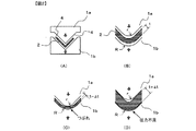
次に図2を用い、屈曲部を持つ積層体成形品の例としてL字型の断面を持つ積層体2の賦形について説明する。図2(A)は長手方向に垂直な断面図であり、紙面垂直方向に一様な断面形状にて金型賦形面4が構成されている。図2(B)はL字型の角部の拡大図である。積層体2を金型にて屈曲させる場合、屈曲部を直角に折り曲げることはできず、多少の丸みをつけねばならない。このように本発明において屈曲部とは積層体2を折り曲げた部分であり、断面において直線部と、直線部に挟まれた曲面部とを有する。図2(B)にて示すと、屈曲部の内側を形成する上型1aでは、角部はrの丸みをつけてある。それに対向する下型1bの角部は、上型1aの角部の丸みrに積層体2の厚みtを足したRの丸みをつける。
Next, the shaping of the
つまり、R=r+tである。このように、成形する積層体成形品の厚みに応じて、金型賦形面4の丸みをあわせなければならない。一方、上記図2(B)の金型を用い、tよりもΔtだけ薄い積層体2を成形する場合を考える。この場合、下型1bを基準に考えると、上型1aの角部の丸みrは上記式で求められる丸みよりもΔtだけ小さいこととなる。そのため、図2(C)に示すように、L字型の角部において直線部よりスキマが狭くなるため、角部において積層体成形品のつぶれが生じてしまう。また逆に上記図2(B)の金型を用い、tよりもΔtだけ厚い積層体2を成形する場合を考える。この場合、下型1bを基準に考えると、上型1aの角部の丸みrは上記式で求められる丸みよりもΔtだけ大きいこととなる。そのため、図2(D)に示すように、L字型の角部において直線部よりスキマが広くなるため、角部において圧力が不足し、成形不良が生じてしまう。このように金型と積層体2の厚みが合っていないと均一な圧力で加圧することはできず、Vpfにムラができてしまう。
That is, R = r + t. In this way, the roundness of the
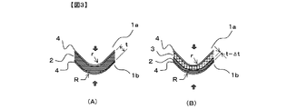
このような不具合を解消するため、本発明では図3(A)に示すように、金型をもっとも厚みのある積層体成形品にあわせて製作する。次に、積層体2の厚みの薄いものを成形する際には、図3(B)に示すように、厚みの薄くなった分、スキマ調整部材3を金型賦形面4と積層体2の間に充填し、加圧時のトータルの厚みを金型の設計上の厚み(もっとも厚みのある積層体成形品の厚み)にあわせる。このようにして、同一の金型で厚みの異なる積層体成形品の製造が可能となる。
In order to eliminate such problems, in the present invention, as shown in FIG. 3 (A), the mold is manufactured in accordance with the laminated product having the greatest thickness. Next, when the
なお、上記スキマ調整部材3に関しても、スキマ調整部材3の厚みに対して屈曲部の曲率半径が小さいと、屈曲部において大きな内外周差を生じる。そのため、屈曲部の外周側では伸ばされ内周側では座屈し、図6(A)に示すような折れ曲がりを生じ、積層体2に均一な圧力付与ができなくなる。そのような場合、図6(B)に示すようにスキマ調整部材3を複数の薄いシート材で形成し、屈曲部における内側と外側での距離の差をシート間のズレにより吸収させることで、折れ曲がり(厚みの差)を生じさせず、積層体2への均一な圧力付与を実現できる。
As for the
なお、断面形状としては上記に示したL字型のみでなく、T字型、H字型、コの字型、Z字型など屈曲部を有する断面形状、および半円形など曲面を有する断面形状であれば、上述の課題が生じ、本発明を好適に用いることができる。 The cross-sectional shape is not limited to the L-shape shown above, but a cross-sectional shape having a bent portion such as a T-shape, H-shape, U-shape, Z-shape, and a cross-sectional shape having a curved surface such as a semicircle. If it is, the above-mentioned subject will arise and the present invention can be used conveniently.
また、長尺の積層体2を賦形する方法として、図4に示すように、金型の型締めおよび型開きの動作を交互に繰り返し、この動作に合わせて、型開き時に長尺の積層体2を搬送することにより、連続的に長尺の積層体成形品を製造することが可能である。この場合、長尺の積層体2が成形型を通過するのに伴い、L字型の折り曲げ位置が、次第に狙いの位置からずれて、2つの側面の長さが異なってくる場合があり、これを防止する手段として、成形型の前後で積層体2、およびL字型積層体成形品を狙いの中心位置に導く導入ガイド6と排出ガイド7を設置することが好ましい。
Also, as a method of shaping the
次に、図4の賦形装置5を用い、長手方向で厚み(積層枚数)の異なる積層体2の賦形について述べる。金型の奥行き長さは、長いほど少ない回数で長尺の成形品を成形できるが、あまり長いと装置の大型化を招くので、その長さは、設備生産性と設備費および作業性を考慮し、適宜選定される。金型にて賦形された積層体2はこの金型の奥行き長さ分搬送され、次の部分が賦形される。これを繰り返し長尺の成形品を製造する。なお、1回の搬送量は正確に金型の奥行き長さではなく、若干短く設定しオーバーラップ部分を作ってもよい。次に、積層体2の厚み(積層枚数)が変わる部分であるが、あらかじめ積層体2にスキマ調整部材3を貼附して賦形する方法では、特別の工夫なく一定の搬送量で賦形を繰り返していけばよい。一方、金型にスキマ調整部材3を取り付け賦形する方法では、金型内では積層体2は一定の厚みであることが好ましく、積層体2の厚みの切り替わり部分が金型の端部にくるように搬送することが好ましい。そして、積層体2の積層枚数(厚み)が切り替わるたびに、スキマ調整部材3の厚みを変更する。このように賦形することで、長手方向で積層枚数が異なる長尺の積層体2であっても、均一な加圧力で品位よく賦形できる。
Next, the shaping of the
また、本発明におけるスキマ調整手段8の一例を図5に示す。スキマ調整手段は巻出ボビン9と巻取ボビン10、および、巻出ボビン9に巻き取られているスキマ調整部材3からなる。すなわち、金型を挟み上流側に巻出ボビン9、下流側に巻取ボビン10が配置されている。ここでスキマ調整部材3は長尺の帯状体としてあり、巻出ボビン9から巻き出され、金型賦形面4を覆い、巻取ボビン10に巻き取られる。スキマ調整部材3の幅は、金型賦形面の奥行き長さと同一かもしくは若干長く選定される。その場合、1回の型締めでは一定厚みにて賦形される。スキマ調整部材3はその長手方向に段階的に厚みを変えて構成されており、スキマ調整部材3を巻き取り、金型賦形面4を覆っているスキマ調整部材3を異なる厚みの部分に切り替えることにより、金型賦形面4と積層体2のスキマを調整する。例えば、2段階に厚みの変わる積層体2の例を述べると、図5(A)に示すように、積層体2の厚みの厚い部分ではスキマ調整部材3の薄い部分3bを金型賦形面4と積層体2の間に介在させ賦形する。次に、積層体2を紙面垂直方向に搬送し、図5(B)に示すように、積層体2の厚みの薄い部分に切り替わった際には、スキマ調整部材3を巻取ボビン10に巻き取り、スキマ調整部材3の厚い部分3aが金型賦形面4に位置するよう移動させる。なお、この場合、スキマ調整部材3は連続的につながっており、積層体2のもっとも厚い部分の賦形においても、金型賦形面4と積層体2の間にスキマ調整部材3が介在するようにしてある。
An example of the clearance adjusting means 8 in the present invention is shown in FIG. The clearance adjusting means includes an unwinding bobbin 9, a winding
また、上記スキマ調整部材3は薄いシート状部材を1枚または複数枚積層して形成してもよく、スキマ調整部材3の長手方向で積層枚数を変えることでスキマ調整部材3の厚みを調整できる。さらに、薄いシート状部材を1枚または複数枚積層してスキマ調整部材3を形成することにより、屈曲部における内側と外側での距離の差をシート間のズレにより吸収させることができる。その場合、各シート状部材は縫糸による縫合など、シート間のズレを許容するような方法で固定されていることが好ましい。また、スキマ調整部材3の表層は全長に渡り連続したシート状部材で形成されていることが、搬送時の引っかかりなどがなく好ましい。
The
積層体成形品は、その求められる剛性のプロファイルに基づき積層枚数が設計される。この積層枚数の切り替わり位置をあらかじめ紙媒体や電子媒体など積層体2の厚みのプロファイルを記録する厚み記録手段に記録しておき、積層体2の搬送量を記録する移動量記録手段に記録された積層体2の搬送量と比較し、厚み記録手段と移動量記録手段に記録された値に基づきスキマ調整部材3の搬送手段によるスキマ調整部材3の搬送量を演算手段にて演算し、積層枚数の切り替わり位置にてスキマ調整部材3の厚みを切り替えることで、長手方向で積層体2の積層枚数が異なる長尺の積層体成形品であっても、均一な加圧力で品位よく成形できる。
The number of laminated sheets is designed based on the required rigidity profile. The switching position of the number of stacked sheets is recorded in advance in a thickness recording unit that records the thickness profile of the
本発明は、金型による賦形であれば、強化繊維基材に限らず、紙やフィルムなどを用いた積層体の賦形にも応用することができ、さらにその応用範囲はこれらに限られるものではない。 The present invention can be applied not only to a reinforcing fiber base material but also to a laminated body using paper or film as long as it is shaped by a mold, and the application range is limited to these. It is not a thing.
1a:上型
1b:下型
2:積層体
3:スキマ調整部材
3a:スキマ調整部材の厚い部分
3b:スキマ調整部材の薄い部分
4:金型賦形面
5:賦形装置
6:導入ガイド
7:排出ガイド
8:スキマ調整手段
9:巻出ボビン
10:巻取ボビン
DESCRIPTION OF
Claims (20)
Priority Applications (1)
| Application Number | Priority Date | Filing Date | Title |
|---|---|---|---|
| JP2007326846A JP5374866B2 (en) | 2006-12-26 | 2007-12-19 | Laminate compression molding apparatus, preform manufacturing method, and prepreg molded body manufacturing method |
Applications Claiming Priority (3)
| Application Number | Priority Date | Filing Date | Title |
|---|---|---|---|
| JP2006349066 | 2006-12-26 | ||
| JP2006349066 | 2006-12-26 | ||
| JP2007326846A JP5374866B2 (en) | 2006-12-26 | 2007-12-19 | Laminate compression molding apparatus, preform manufacturing method, and prepreg molded body manufacturing method |
Publications (3)
| Publication Number | Publication Date |
|---|---|
| JP2008179130A JP2008179130A (en) | 2008-08-07 |
| JP2008179130A5 JP2008179130A5 (en) | 2011-02-03 |
| JP5374866B2 true JP5374866B2 (en) | 2013-12-25 |
Family
ID=39723391
Family Applications (1)
| Application Number | Title | Priority Date | Filing Date |
|---|---|---|---|
| JP2007326846A Expired - Fee Related JP5374866B2 (en) | 2006-12-26 | 2007-12-19 | Laminate compression molding apparatus, preform manufacturing method, and prepreg molded body manufacturing method |
Country Status (1)
| Country | Link |
|---|---|
| JP (1) | JP5374866B2 (en) |
Families Citing this family (7)
| Publication number | Priority date | Publication date | Assignee | Title |
|---|---|---|---|---|
| EP2051845B1 (en) * | 2006-08-17 | 2010-11-03 | Airbus Deutschland GmbH | Production method for a workpiece composed of a fibre-composite material and fibre-composite components in the form of a profile with a profile cross section which varies over its length |
| JP4908266B2 (en) * | 2007-03-05 | 2012-04-04 | 株式会社ジャムコ | Method for continuously forming composite material having stepwise cross-sectional thickness |
| JP5322594B2 (en) * | 2008-11-12 | 2013-10-23 | 株式会社ジャムコ | Continuous molding method for composite molds with different cross sections |
| DE102013209611A1 (en) * | 2013-05-23 | 2014-11-27 | Bayerische Motoren Werke Aktiengesellschaft | Method for producing a tool for the production of a fiber composite component |
| JP6554128B2 (en) | 2017-02-28 | 2019-07-31 | 株式会社Subaru | Manufacturing method of fiber reinforced composite material |
| JP6554130B2 (en) | 2017-03-14 | 2019-07-31 | 株式会社Subaru | Manufacturing method of fiber reinforced composite material |
| CN112590256A (en) * | 2020-12-10 | 2021-04-02 | 中机精密成形产业技术研究院(安徽)股份有限公司 | Automatic compression molding process for upper box body of power battery made of composite material |
Family Cites Families (3)
| Publication number | Priority date | Publication date | Assignee | Title |
|---|---|---|---|---|
| JP3204529B2 (en) * | 1992-02-26 | 2001-09-04 | 昭和飛行機工業株式会社 | Method for manufacturing curved honeycomb panel |
| JP3296625B2 (en) * | 1993-06-11 | 2002-07-02 | 三井化学株式会社 | Manufacturing method of composite foam molded article |
| KR100414685B1 (en) * | 1995-12-19 | 2004-06-24 | 듀라맥스 머린 엘엘씨 | Fender Protection Structure Manufacturing Method |
-
2007
- 2007-12-19 JP JP2007326846A patent/JP5374866B2/en not_active Expired - Fee Related
Also Published As
| Publication number | Publication date |
|---|---|
| JP2008179130A (en) | 2008-08-07 |
Similar Documents
| Publication | Publication Date | Title |
|---|---|---|
| JP5374866B2 (en) | Laminate compression molding apparatus, preform manufacturing method, and prepreg molded body manufacturing method | |
| US7186361B2 (en) | Method and apparatus for continuous molding of fiber reinforced plastic member with curvature | |
| US8052910B2 (en) | Continuous molding method of composite material having stepwise sectional thickness | |
| JP5200536B2 (en) | Preform manufacturing method and manufacturing apparatus | |
| WO2011046137A1 (en) | Method and device for manufacturing beam member | |
| US8944128B2 (en) | Device for tensioning a preform | |
| JP4952056B2 (en) | Preform manufacturing method and preform manufacturing apparatus | |
| US20110086199A1 (en) | Method and device for producing a curved profile made from composite material and resulting profile | |
| US20080053599A1 (en) | Method for continuously preforming composite material in uncured state | |
| JP5315713B2 (en) | Method for manufacturing preform for FRP member | |
| JP5937894B2 (en) | Composite stringer continuous preform equipment | |
| US20140251529A1 (en) | Method for producing an extruded stiffened panel, and device for implementing same | |
| JP2005059596A (en) | Method for forming stepped laminate | |
| US20140291889A1 (en) | Device and method for molding fiber-reinforced plastic member | |
| JP2020059145A (en) | Laminate device and laminate method of prepreg tape | |
| US11845234B2 (en) | Articulated forming caul for composite blank vacuum forming | |
| US8273206B2 (en) | Method for continuously forming composite material shape member having varied cross-sectional shape | |
| WO2021193268A1 (en) | Method and device for producing composite material molded article | |
| JP2008179130A5 (en) | ||
| JP7423857B2 (en) | Composite molding method | |
| JP5435330B2 (en) | Method for manufacturing reinforcing fiber composite beam | |
| JP2004330474A (en) | Method for manufacturing composite material product | |
| JP2010173166A (en) | Compression-shaping apparatus and method, fiber-reinforced composite material and preform, and method of manufacturing them | |
| JP2009234065A (en) | Manufacturing process of pressing type forming apparatus of reinforcing fiber substrate, and preform, and manufacturing process of fiber-reinforced composite material | |
| KR102045513B1 (en) | Manufacturing method of rollable plate |
Legal Events
| Date | Code | Title | Description |
|---|---|---|---|
| A521 | Request for written amendment filed |
Free format text: JAPANESE INTERMEDIATE CODE: A523 Effective date: 20101215 |
|
| A621 | Written request for application examination |
Free format text: JAPANESE INTERMEDIATE CODE: A621 Effective date: 20101215 |
|
| A977 | Report on retrieval |
Free format text: JAPANESE INTERMEDIATE CODE: A971007 Effective date: 20121031 |
|
| A131 | Notification of reasons for refusal |
Free format text: JAPANESE INTERMEDIATE CODE: A131 Effective date: 20130618 |
|
| A521 | Request for written amendment filed |
Free format text: JAPANESE INTERMEDIATE CODE: A523 Effective date: 20130808 |
|
| TRDD | Decision of grant or rejection written | ||
| A01 | Written decision to grant a patent or to grant a registration (utility model) |
Free format text: JAPANESE INTERMEDIATE CODE: A01 Effective date: 20130827 |
|
| A61 | First payment of annual fees (during grant procedure) |
Free format text: JAPANESE INTERMEDIATE CODE: A61 Effective date: 20130909 |
|
| R151 | Written notification of patent or utility model registration |
Ref document number: 5374866 Country of ref document: JP Free format text: JAPANESE INTERMEDIATE CODE: R151 |
|
| LAPS | Cancellation because of no payment of annual fees |