EP3763409B1 - Asymmetrical nasal delivery elements and fittings for nasal interfaces - Google Patents
Asymmetrical nasal delivery elements and fittings for nasal interfaces Download PDFInfo
- Publication number
- EP3763409B1 EP3763409B1 EP20183115.3A EP20183115A EP3763409B1 EP 3763409 B1 EP3763409 B1 EP 3763409B1 EP 20183115 A EP20183115 A EP 20183115A EP 3763409 B1 EP3763409 B1 EP 3763409B1
- Authority
- EP
- European Patent Office
- Prior art keywords
- nasal
- interface
- sectional area
- cross
- outer circumference
- Prior art date
- Legal status (The legal status is an assumption and is not a legal conclusion. Google has not performed a legal analysis and makes no representation as to the accuracy of the status listed.)
- Active
Links
- 239000007789 gas Substances 0.000 claims description 66
- 230000036961 partial effect Effects 0.000 claims description 10
- 238000007789 sealing Methods 0.000 claims description 6
- 239000000463 material Substances 0.000 description 33
- 239000007933 dermal patch Substances 0.000 description 31
- 210000001331 nose Anatomy 0.000 description 29
- 210000000088 lip Anatomy 0.000 description 26
- 238000002560 therapeutic procedure Methods 0.000 description 24
- CURLTUGMZLYLDI-UHFFFAOYSA-N Carbon dioxide Chemical compound O=C=O CURLTUGMZLYLDI-UHFFFAOYSA-N 0.000 description 22
- 210000003128 head Anatomy 0.000 description 18
- 230000029058 respiratory gaseous exchange Effects 0.000 description 15
- QVGXLLKOCUKJST-UHFFFAOYSA-N atomic oxygen Chemical compound [O] QVGXLLKOCUKJST-UHFFFAOYSA-N 0.000 description 11
- 229910002092 carbon dioxide Inorganic materials 0.000 description 11
- 239000001569 carbon dioxide Substances 0.000 description 11
- 230000000694 effects Effects 0.000 description 11
- 239000001301 oxygen Substances 0.000 description 11
- 229910052760 oxygen Inorganic materials 0.000 description 11
- 239000000853 adhesive Substances 0.000 description 9
- 230000001070 adhesive effect Effects 0.000 description 9
- 230000007246 mechanism Effects 0.000 description 9
- 238000000034 method Methods 0.000 description 9
- 239000000758 substrate Substances 0.000 description 9
- 230000007423 decrease Effects 0.000 description 8
- 230000002829 reductive effect Effects 0.000 description 8
- 241000083547 Columella Species 0.000 description 7
- 230000008878 coupling Effects 0.000 description 7
- 238000010168 coupling process Methods 0.000 description 7
- 238000005859 coupling reaction Methods 0.000 description 7
- 238000009423 ventilation Methods 0.000 description 7
- 230000000241 respiratory effect Effects 0.000 description 6
- 230000008901 benefit Effects 0.000 description 5
- 239000004033 plastic Substances 0.000 description 5
- 229920003023 plastic Polymers 0.000 description 5
- 238000003780 insertion Methods 0.000 description 4
- 230000003434 inspiratory effect Effects 0.000 description 4
- 230000004048 modification Effects 0.000 description 4
- 238000012986 modification Methods 0.000 description 4
- 230000001815 facial effect Effects 0.000 description 3
- 238000010438 heat treatment Methods 0.000 description 3
- 230000014759 maintenance of location Effects 0.000 description 3
- 230000002093 peripheral effect Effects 0.000 description 3
- 230000000153 supplemental effect Effects 0.000 description 3
- 229920002725 thermoplastic elastomer Polymers 0.000 description 3
- XLYOFNOQVPJJNP-UHFFFAOYSA-N water Substances O XLYOFNOQVPJJNP-UHFFFAOYSA-N 0.000 description 3
- 239000000443 aerosol Substances 0.000 description 2
- 230000004888 barrier function Effects 0.000 description 2
- 230000015572 biosynthetic process Effects 0.000 description 2
- 239000011248 coating agent Substances 0.000 description 2
- 238000000576 coating method Methods 0.000 description 2
- 210000005069 ears Anatomy 0.000 description 2
- 239000012530 fluid Substances 0.000 description 2
- 238000005755 formation reaction Methods 0.000 description 2
- 239000000416 hydrocolloid Substances 0.000 description 2
- 230000037431 insertion Effects 0.000 description 2
- 238000009434 installation Methods 0.000 description 2
- 229920001296 polysiloxane Polymers 0.000 description 2
- 230000009467 reduction Effects 0.000 description 2
- 230000003019 stabilising effect Effects 0.000 description 2
- 230000003068 static effect Effects 0.000 description 2
- 208000006545 Chronic Obstructive Pulmonary Disease Diseases 0.000 description 1
- 206010014561 Emphysema Diseases 0.000 description 1
- 206010021143 Hypoxia Diseases 0.000 description 1
- 239000004677 Nylon Substances 0.000 description 1
- 206010035664 Pneumonia Diseases 0.000 description 1
- 206010038687 Respiratory distress Diseases 0.000 description 1
- 230000004308 accommodation Effects 0.000 description 1
- 238000009825 accumulation Methods 0.000 description 1
- 230000001154 acute effect Effects 0.000 description 1
- 210000003484 anatomy Anatomy 0.000 description 1
- 230000003466 anti-cipated effect Effects 0.000 description 1
- 208000006673 asthma Diseases 0.000 description 1
- 239000000560 biocompatible material Substances 0.000 description 1
- 206010006451 bronchitis Diseases 0.000 description 1
- 230000000295 complement effect Effects 0.000 description 1
- 239000000470 constituent Substances 0.000 description 1
- 238000010276 construction Methods 0.000 description 1
- 230000001351 cycling effect Effects 0.000 description 1
- 230000003247 decreasing effect Effects 0.000 description 1
- 230000001419 dependent effect Effects 0.000 description 1
- 230000003467 diminishing effect Effects 0.000 description 1
- 238000001035 drying Methods 0.000 description 1
- 230000002500 effect on skin Effects 0.000 description 1
- 239000013013 elastic material Substances 0.000 description 1
- 239000004744 fabric Substances 0.000 description 1
- 239000000835 fiber Substances 0.000 description 1
- 239000006261 foam material Substances 0.000 description 1
- 230000002209 hydrophobic effect Effects 0.000 description 1
- 230000001146 hypoxic effect Effects 0.000 description 1
- 230000003993 interaction Effects 0.000 description 1
- 230000000670 limiting effect Effects 0.000 description 1
- 239000007788 liquid Substances 0.000 description 1
- 230000000116 mitigating effect Effects 0.000 description 1
- 210000002850 nasal mucosa Anatomy 0.000 description 1
- 229920001778 nylon Polymers 0.000 description 1
- 230000037361 pathway Effects 0.000 description 1
- 230000000737 periodic effect Effects 0.000 description 1
- 239000004417 polycarbonate Substances 0.000 description 1
- 229920000515 polycarbonate Polymers 0.000 description 1
- 230000036387 respiratory rate Effects 0.000 description 1
- 201000002859 sleep apnea Diseases 0.000 description 1
- 230000006641 stabilisation Effects 0.000 description 1
- 239000003381 stabilizer Substances 0.000 description 1
- 230000035882 stress Effects 0.000 description 1
- 230000003319 supportive effect Effects 0.000 description 1
- 239000004753 textile Substances 0.000 description 1
- 230000001225 therapeutic effect Effects 0.000 description 1
- 230000007704 transition Effects 0.000 description 1
- 238000011282 treatment Methods 0.000 description 1
Images


Classifications
-
- A—HUMAN NECESSITIES
- A61—MEDICAL OR VETERINARY SCIENCE; HYGIENE
- A61M—DEVICES FOR INTRODUCING MEDIA INTO, OR ONTO, THE BODY; DEVICES FOR TRANSDUCING BODY MEDIA OR FOR TAKING MEDIA FROM THE BODY; DEVICES FOR PRODUCING OR ENDING SLEEP OR STUPOR
- A61M16/00—Devices for influencing the respiratory system of patients by gas treatment, e.g. mouth-to-mouth respiration; Tracheal tubes
- A61M16/06—Respiratory or anaesthetic masks
- A61M16/0666—Nasal cannulas or tubing
- A61M16/0672—Nasal cannula assemblies for oxygen therapy
-
- A—HUMAN NECESSITIES
- A61—MEDICAL OR VETERINARY SCIENCE; HYGIENE
- A61M—DEVICES FOR INTRODUCING MEDIA INTO, OR ONTO, THE BODY; DEVICES FOR TRANSDUCING BODY MEDIA OR FOR TAKING MEDIA FROM THE BODY; DEVICES FOR PRODUCING OR ENDING SLEEP OR STUPOR
- A61M16/00—Devices for influencing the respiratory system of patients by gas treatment, e.g. mouth-to-mouth respiration; Tracheal tubes
- A61M16/06—Respiratory or anaesthetic masks
- A61M16/0683—Holding devices therefor
- A61M16/0688—Holding devices therefor by means of an adhesive
-
- A—HUMAN NECESSITIES
- A61—MEDICAL OR VETERINARY SCIENCE; HYGIENE
- A61M—DEVICES FOR INTRODUCING MEDIA INTO, OR ONTO, THE BODY; DEVICES FOR TRANSDUCING BODY MEDIA OR FOR TAKING MEDIA FROM THE BODY; DEVICES FOR PRODUCING OR ENDING SLEEP OR STUPOR
- A61M16/00—Devices for influencing the respiratory system of patients by gas treatment, e.g. mouth-to-mouth respiration; Tracheal tubes
- A61M16/0003—Accessories therefor, e.g. sensors, vibrators, negative pressure
- A61M2016/0027—Accessories therefor, e.g. sensors, vibrators, negative pressure pressure meter
-
- A—HUMAN NECESSITIES
- A61—MEDICAL OR VETERINARY SCIENCE; HYGIENE
- A61M—DEVICES FOR INTRODUCING MEDIA INTO, OR ONTO, THE BODY; DEVICES FOR TRANSDUCING BODY MEDIA OR FOR TAKING MEDIA FROM THE BODY; DEVICES FOR PRODUCING OR ENDING SLEEP OR STUPOR
- A61M16/00—Devices for influencing the respiratory system of patients by gas treatment, e.g. mouth-to-mouth respiration; Tracheal tubes
- A61M16/0003—Accessories therefor, e.g. sensors, vibrators, negative pressure
- A61M2016/003—Accessories therefor, e.g. sensors, vibrators, negative pressure with a flowmeter
-
- A—HUMAN NECESSITIES
- A61—MEDICAL OR VETERINARY SCIENCE; HYGIENE
- A61M—DEVICES FOR INTRODUCING MEDIA INTO, OR ONTO, THE BODY; DEVICES FOR TRANSDUCING BODY MEDIA OR FOR TAKING MEDIA FROM THE BODY; DEVICES FOR PRODUCING OR ENDING SLEEP OR STUPOR
- A61M16/00—Devices for influencing the respiratory system of patients by gas treatment, e.g. mouth-to-mouth respiration; Tracheal tubes
- A61M16/10—Preparation of respiratory gases or vapours
- A61M16/1005—Preparation of respiratory gases or vapours with O2 features or with parameter measurement
- A61M2016/102—Measuring a parameter of the content of the delivered gas
- A61M2016/1025—Measuring a parameter of the content of the delivered gas the O2 concentration
-
- A—HUMAN NECESSITIES
- A61—MEDICAL OR VETERINARY SCIENCE; HYGIENE
- A61M—DEVICES FOR INTRODUCING MEDIA INTO, OR ONTO, THE BODY; DEVICES FOR TRANSDUCING BODY MEDIA OR FOR TAKING MEDIA FROM THE BODY; DEVICES FOR PRODUCING OR ENDING SLEEP OR STUPOR
- A61M16/00—Devices for influencing the respiratory system of patients by gas treatment, e.g. mouth-to-mouth respiration; Tracheal tubes
- A61M16/10—Preparation of respiratory gases or vapours
- A61M16/1005—Preparation of respiratory gases or vapours with O2 features or with parameter measurement
- A61M2016/102—Measuring a parameter of the content of the delivered gas
- A61M2016/103—Measuring a parameter of the content of the delivered gas the CO2 concentration
-
- A—HUMAN NECESSITIES
- A61—MEDICAL OR VETERINARY SCIENCE; HYGIENE
- A61M—DEVICES FOR INTRODUCING MEDIA INTO, OR ONTO, THE BODY; DEVICES FOR TRANSDUCING BODY MEDIA OR FOR TAKING MEDIA FROM THE BODY; DEVICES FOR PRODUCING OR ENDING SLEEP OR STUPOR
- A61M2202/00—Special media to be introduced, removed or treated
- A61M2202/02—Gases
- A61M2202/0208—Oxygen
-
- A—HUMAN NECESSITIES
- A61—MEDICAL OR VETERINARY SCIENCE; HYGIENE
- A61M—DEVICES FOR INTRODUCING MEDIA INTO, OR ONTO, THE BODY; DEVICES FOR TRANSDUCING BODY MEDIA OR FOR TAKING MEDIA FROM THE BODY; DEVICES FOR PRODUCING OR ENDING SLEEP OR STUPOR
- A61M2202/00—Special media to be introduced, removed or treated
- A61M2202/02—Gases
- A61M2202/0225—Carbon oxides, e.g. Carbon dioxide
-
- A—HUMAN NECESSITIES
- A61—MEDICAL OR VETERINARY SCIENCE; HYGIENE
- A61M—DEVICES FOR INTRODUCING MEDIA INTO, OR ONTO, THE BODY; DEVICES FOR TRANSDUCING BODY MEDIA OR FOR TAKING MEDIA FROM THE BODY; DEVICES FOR PRODUCING OR ENDING SLEEP OR STUPOR
- A61M2205/00—General characteristics of the apparatus
- A61M2205/42—Reducing noise
-
- A—HUMAN NECESSITIES
- A61—MEDICAL OR VETERINARY SCIENCE; HYGIENE
- A61M—DEVICES FOR INTRODUCING MEDIA INTO, OR ONTO, THE BODY; DEVICES FOR TRANSDUCING BODY MEDIA OR FOR TAKING MEDIA FROM THE BODY; DEVICES FOR PRODUCING OR ENDING SLEEP OR STUPOR
- A61M2206/00—Characteristics of a physical parameter; associated device therefor
- A61M2206/10—Flow characteristics
- A61M2206/20—Flow characteristics having means for promoting or enhancing the flow, actively or passively
-
- A—HUMAN NECESSITIES
- A61—MEDICAL OR VETERINARY SCIENCE; HYGIENE
- A61M—DEVICES FOR INTRODUCING MEDIA INTO, OR ONTO, THE BODY; DEVICES FOR TRANSDUCING BODY MEDIA OR FOR TAKING MEDIA FROM THE BODY; DEVICES FOR PRODUCING OR ENDING SLEEP OR STUPOR
- A61M2230/00—Measuring parameters of the user
- A61M2230/20—Blood composition characteristics
- A61M2230/205—Blood composition characteristics partial oxygen pressure (P-O2)
-
- A—HUMAN NECESSITIES
- A61—MEDICAL OR VETERINARY SCIENCE; HYGIENE
- A61M—DEVICES FOR INTRODUCING MEDIA INTO, OR ONTO, THE BODY; DEVICES FOR TRANSDUCING BODY MEDIA OR FOR TAKING MEDIA FROM THE BODY; DEVICES FOR PRODUCING OR ENDING SLEEP OR STUPOR
- A61M2230/00—Measuring parameters of the user
- A61M2230/40—Respiratory characteristics
- A61M2230/43—Composition of exhalation
- A61M2230/432—Composition of exhalation partial CO2 pressure (P-CO2)
-
- A—HUMAN NECESSITIES
- A61—MEDICAL OR VETERINARY SCIENCE; HYGIENE
- A61M—DEVICES FOR INTRODUCING MEDIA INTO, OR ONTO, THE BODY; DEVICES FOR TRANSDUCING BODY MEDIA OR FOR TAKING MEDIA FROM THE BODY; DEVICES FOR PRODUCING OR ENDING SLEEP OR STUPOR
- A61M2230/00—Measuring parameters of the user
- A61M2230/40—Respiratory characteristics
- A61M2230/43—Composition of exhalation
- A61M2230/435—Composition of exhalation partial O2 pressure (P-O2)
-
- A—HUMAN NECESSITIES
- A61—MEDICAL OR VETERINARY SCIENCE; HYGIENE
- A61M—DEVICES FOR INTRODUCING MEDIA INTO, OR ONTO, THE BODY; DEVICES FOR TRANSDUCING BODY MEDIA OR FOR TAKING MEDIA FROM THE BODY; DEVICES FOR PRODUCING OR ENDING SLEEP OR STUPOR
- A61M2240/00—Specially adapted for neonatal use
Definitions
- the present invention generally relates to a nasal interface. More particularly, the present invention relates to asymmetrical nasal delivery elements for a nasal interface and other arrangements for achieving asymmetric flow or partial unidirectional flow.
- Humidifiers are used to provide humidified respiratory gases to a patient. Gases are delivered to the patient via a patient interface. Examples of a patient interface include an oral mask, a nasal mask, a nasal cannula, a combination of oral and nasal mask, and the like.
- Nasal interfaces can be used to deliver a high flow of gases to a patient.
- Nasal delivery elements are inserted into the nose of a patient to deliver the required therapy.
- the nasal delivery elements may be required to seal or semi-seal at the nose, or may not be required to seal at the nose, to deliver the therapy.
- Nasal high flow typically is a non-sealing therapy that delivers relatively high-volume flow to the patient through a nasal interface, which flow may be sufficient to meet or exceed the patient's inspiratory flow rate.
- a nasal prong interface comprising asymmetrical prongs particularly useful for patients with substantially asymmetrical and/or deformed nose shapes is disclosed in GB2493520 .
- prongs for nasal interfaces exist in the prior art
- an aspect of at least one of the embodiments disclosed herein includes the realization that there are problems with the insertion of these prior art prongs into the nose of a patient.
- Prongs in the art require high motor speeds of the flow generating device to deliver the desired flow rate to the patient.
- a flow generating device is a device that delivers a flow of gas to a patient.
- the static pressure may increase to equal the backpressure in the system, which may potentially reach undesirable levels.
- the undesirably high static pressure is intensified for child and infant prongs because the reduced prong diameter required to fit the nares of a child or infant can increase resistance to flow through the interface to the patient.
- a nasal delivery element of a nasal interface with a smaller diameter may have a high leak and as a result will deliver lower pressure to a patient.
- a large diameter may not be as efficient at clearing anatomical dead space from the patient airways.
- a system uses nasal high flow in combination with asymmetrical nasal delivery elements for a nasal interface to deliver respiratory gases to a patient via an asymmetrical flow.
- Asymmetrical nasal delivery elements can provide the patient with increased dead space clearance in the upper airways. Due to a decrease in peak expiratory pressure, noise can be reduced, and asymmetrical nasal delivery elements may provide a more desirable therapy for infant use due to mitigation of the risk of completely sealing the airways of the patient.
- the asymmetry of the nasal delivery elements can reduce the resistance to flow through the interface, which can achieve desired flow rates using lower backpressure and/or lower motor speeds of the flow generating device.
- Different embodiments disclose a system that modifies the pressure effects during nasal high flow while maintaining efficient dead space clearance, by adding fittings such as but not limited to, sleeves or inserts to the nasal interface. It may increase pressure swings generated during breathing, increase jetting effects, improve patient comfort, more efficiently clear dead space and increase expiratory pressure.
- fittings may reduce the required operational flow, which may result in less noise, reductions in heating, oxygen and water usage, desirable or optimised therapeutic effects of nasal high flow. Thus a lower flow rate may be able to achieve a higher pressure.
- the present invention provides a nasal interface as claimed.
- the present invention relates to a nasal interface comprising asymmetrical nasal delivery elements, the asymmetrical nasal delivery elements comprising a first nasal delivery element that is a prong and a second nasal delivery element that is a prong or a pillow, the prong or pillow of the second nasal delivery element having a greater internal cross-sectional area on a plane perpendicular to the airflow direction than a prong of the first nasal delivery element, which causes asymmetrical flow or partial unidirectional flow of gases at the nares of a subject, to improve dead space clearance, preferably to reduce the volume of anatomical dead space within the volume of the airway of a subject, to reduce peak expiratory pressure, to reduce noise, and/or to reduce resistance to flow at the patient interface.
- the second cross-sectional area may be about 1.5, 2, 2.5, 3, 3.5, 4, 4.5, 5, 5.5, 6, 6.5, 7, 7.5, 8, 8.5, 9, 9.5, 10, 10.5, 11, 11.5, 12, 12.5, 13, 13.5, 14, 14.5, 15, 15.5, 16, 16.5, 17, 17.5, 18, 18.5, 19, 19.5, 20, 20.5, 21, 21.5, 22, 22.5, 23, 23.5, 24, 24.5, 25, 25.5, 26, 26.5, 27, 27.5, 28, 28.5, 29, 29.5, 30, 30.5, 31, 31.5, 32, 32.5, 33, 33.5, 34, 34.5, 35, 35.5, 36, 36.5, 37, 37.5, 38, 38.5, 39, 39.5, 40, 40.5, 41, 41.5, 42, 42.5, 43, 43.5, 44, 44.5, 45, 45.5, 46, 46.5, 47, 47.5, 48, 48.5, 49, 49.5, or 50 mm 2 , and useful ranges may be selected between any of these values (for example, about 1.5 to about 10, about 1.5 to about 20, about 1.5 to about 30, about
- the first cross-sectional area may be about 20, 21, 22, 23, 24, 25, 26, 27, 28, 29, 30, 31, 32, 33, 34, 35, 36, 37, 38, 39, 40, 41, 42, 43, 44, 45, 46, 47, 48, 49, 50, 51, 52, 53, 54, 55, 56, 57, 58, 59, 60, 61, 62, 63, 64, 65, 66, 67, 68, 69, 70, 71, 72, 73, 74, 75, 76, 78, 79, or 80% of the second cross-sectional area, and useful ranges may be selected between any of these values (for example, about 20 to about 30, about 20 to about 40, about 20 to about 50, about 20 to about 60, about 20 to about 70, and about 20 to about 80%).
- the second cross-sectional area may be about 1.5 to about 50 mm 2 and the first cross-sectional area may be about 20% to about 80% of the second cross-sectional area, preferably about 50%.
- the ratio of the first cross-sectional area to the second cross-sectional area may be at least about 1:1.2, 1:1.25, 1:1.3, 1:1.35, 1:1.4, 1:1.45, 1:1.5, 1:1.55, 1:1.6, 1:1.65, 1:1.7, 1:1.75, 1:1.8, 1:1.85, 1:1.9, 1:1.95, 1:2, 1:2.05, 1:2.1, 1:2.15, 1:2.2, 1:2.25, 1:2.3, 1:2.35, 1:2.4, 1:2.45, or 1:2.5, and useful ranges may be selected between any of these values (for example, about 1:1.2 to about 1:2.5). Preferably the ratio may be about 1:2.
- the second outer circumference may be about 7.5, 8, 8.5, 9, 9.5, 10, 10.5, 11, 11.5, 12, 12.5, 13, 13.5, 14, 14.5, 15, 15.5, 16, 16.5, 17, 17.5, 18, 18.5, 19, 19.5, 20, 20.5, 21, 21.5, 22, 22.5, 23, 23.5, 24, 24.5, 25, 25.5, 26, 26.5, 27, 27.5, 28, 28.5, 29, 29.5, or 30 mm, and useful ranges may be selected between any of these values (for example, about 7.5 to about 10, about 7.5 to about 15, about 7.5 to about 20, about 7.5 to about 25, and about 7.5 to about 30 mm).
- the first outer circumference may be about 20, 21, 22, 23, 24, 25, 26, 27, 28, 29, 30, 31, 32, 33, 34, 35, 36, 37, 38, 39, 40, 41, 42, 43, 44, 45, 46, 47, 48, 49, 50, 51, 52, 53, 54, 55, 56, 57, 58, 59, 60, 61, 62, 63, 64, 65, 66, 67, 68, 69, 70, 71, 72, 73, 74, 75, 76, 78, 79, or 80% of the second outer circumference, and useful ranges may be selected between any of these values (for example, about 20 to about 30, about 20 to about 40, about 20 to about 50, about 20 to about 60, about 20 to about 70, and about 20 to about 80%).
- the second outer circumference may be about 7.5 mm to about 30 mm and the first outer circumference may be about 20% to about 80% of the second outer circumference, preferably about 50%.
- the ratio of the first outer circumference to the second outer circumference may be at least about 1:1.2, 1:1.25, 1:1.3, 1:1.35, 1:1.4, 1:1.45, 1:1.5, 1:1.55, 1:1.6, 1:1.65, 1:1.7, 1:1.75, 1:1.8, 1:1.85, 1:1.9, 1:1.95, 1:2, 1:2.05, 1:2.1, 1:2.15, 1:2.2, 1:2.25, 1:2.3, 1:2.35, 1:2.4, 1:2.45, or 1:2.5, and useful ranges may be selected between any of these values (for example, about 1:1.2 to about 1:2.5). Preferably the ratio may be about 1:2.
- the nasal interface may be adapted so that fittings may be attached to the nasal delivery elements of the interface to alter the shape or inner or outer diameters of the nasal delivery elements to efficiently clear dead space, reduce operational flow, and reduce noise.
- one nasal delivery element may comprise a single lumen, or both nasal delivery elements may comprise a single lumen.
- a user interface assembly comprising a nasal interface as described herein, a securement system for the user interface and/or a component associated with the user interface (e.g. such as a tube or tubing), and/or a tube connected to the user interface providing at least a part of a breathing circuit for a user of the interface.
- the securement system may comprise a two-part releasable attachment (or connection) arrangement, the arrangement comprising a dermal patch and a user interface patch,
- the lip is a barrier.
- the lip is deformable.
- the lip extends at least about the perimeter of a region substantially adjacent to a prong associated with the backing.
- the lip is an endless lip extending about the perimeter of the rear surface of the backing.
- the lip is a series of one or more separate lips.
- the one or more separate lips are adjacent or adjoining or overlapping lip portions.
- the lip in use, substantially forms a fluid (e.g. liquid) seal, or barrier to fluid, between the rear surface of the backing and a cannula facing surface of the user interface patch.
- a fluid e.g. liquid
- the backing is substantially planar or flat or contoured (such as a pre-formed curve) backing configured to rest on a user's face.
- the backing assists as a stabilizer of the prong(s) in the nare(s) of a user.
- the at least one backing extends laterally outward from the at least one nasal prong, away from the septum of a user.
- the lip(s) is hydrophobic.
- the lip(s) comprises at least one outer perimeter lip portion and at least one inner perimeter lip portion, each of said lips provided for contacting with a user's face.
- the face mount part may comprise at least one substantially horizontal side entry passage to the interior of the base portion for releasably receiving the outlet of the manifold part therethrough.
- the face mount part may comprise a pair of opposed side entry passages to the interior of the base portion, each adapted to releasably receive the outlet of the manifold part therethrough.
- gases flow manifold part may be formed from a relatively harder material than the face mount part.
- the gases flow manifold part may be formed from a substantially rigid plastics material, such as polycarbonate.
- the face mount part may be formed from a substantially soft plastics material, such as silicone.
- the nasal interface may further comprise headgear comprising a strap forming a part of the headgear for assisting in retaining or stabilising of the nasal interface upon a user, wherein the strap, or a section of the strap, to be located upon or to be placed in contact with the face or a portion of a user's face includes a surface region for frictionally engaging with the user's face, the surface region being of a relatively higher frictional surface material than the remainder of the strap forming the or a part of the headgear.
- the strap or a respective section of the strap includes two symmetric surface regions for frictionally engaging with two symmetric portions on either side of the user's face.
- a remainder of the strap is arranged to extend as a non-facial contacting strap or section of strap which is to extend beyond the user's face or the portion of the user's face.
- each surface region for frictionally engaging with the user's face or a portion of the user's face including the relatively higher frictional surface material assists with retaining or stabilising of a patient interface upon the face of a user.
- each surface region comprises a material applied to the strap or the respective section of strap.
- the material applied is in the form of a sleeve positioned about the strap or the respective section of strap.
- the sleeve is configured to removeably couple about the strap or the section of the strap.
- the strap or the respective section of the strap extends through a passage in the sleeve.
- the strap or the respective section of the strap is adapted to be threaded through the passage.
- the material applied is in the form of a material coated upon the strap or the respective section of strap.
- the material applied is over-moulded upon the strap or the respective section of strap.
- the material applied is smooth and comfortable for skin contact.
- the material applied is a thermoplastic elastomer.
- each surface region is a surface of wider surface area at an end to be located more adjacent to the patient interface than the surface area of an opposing end more distant from the patient interface.
- each surface region tapers from the relatively wider surface area to the relatively lesser surface area.
- the strap or each section of the strap including the surface region further comprises a component of the strap configured to releasably couple the patient interface.
- each portion of the user's face includes a cheek of the user.
- the method may comprise improving the ventilation of a subject in need thereof includes reducing peak expiratory pressure, reducing noise during expiration, and/or reducing resistance to flow at the patient interface.
- the gas may be delivered to one nare of the subject at a first flow rate of about 5, 10, 15, 20, 25, 30, 35, 40, 45, 50, 55, or 60 L/min, and useful ranges may be selected between any of these values (for example, about 5 to about 10, about 5 to about 20, about 5 to about 30, about 5 to about 40, about 5 to about 50, and about 5 to about 60 L/min).
- the flow rate to the other nare of the subject may be at a second flow rate that may be about 20, 21, 22, 23, 24, 25, 26, 27, 28, 29, 30, 31, 32, 33, 34, 35, 36, 37, 38, 39, 40, 41, 42, 43, 44, 45, 46, 47, 48, 49, 50, 51, 52, 53, 54, 55, 56, 57, 58, 59, 60, 61, 62, 63, 64, 65, 66, 67, 68, 69, 70, 71, 72, 73, 74, 75, 76, 78, 79, or 80% of the first flow rate, and useful ranges may be selected between any of these values (for example, about 20 to about 30, about 20 to about 40, about 20 to about 50, about 20 to about 60, about 20 to about 70, and about 20 to about 80%).
- the gas may be delivered to one nare of the subject at a first flow rate of about 5 L/min to about 60 L/min and to the other nare of the subject at a second flow rate that may be about 20% to about 80% of the first flow rate, preferably about 50%.
- the subject's mouth may be closed or sealed.
- the subject's mouth may be open.
- the method may further comprise inserting a mouthpiece into the mouth of the subject, to maintain a leak from the mouth of the subject into the atmosphere, a negative pressure line, or an expiratory limb, or to increase or control dead space clearance.
- Sound generated by the expiration of gas through the nares may be less than the sound generated by nasal expiration during nasal high flow therapy conducted at an equivalent flow rate using a nasal interface that comprises symmetrical nasal delivery elements.
- the gas pressure in the subject's airway may be estimated and/or measured.
- Tthe average gas pressure in the subject's airway may be maintained at a level of less than about 4 cm H 2 O, preferably at a level of less than about 3.5, 3, 2.5, 5 or 1 cm H 2 O, preferably with the subject's mouth open or closed, preferably with the subject's mouth closed.
- the oxygen concentration of the subject's airway may be measured.
- the oxygen concentration of the subject's airway may be maintained at a substantially constant level or increased.
- the carbon dioxide concentration of the subject's airway may be measured.
- the carbon dioxide concentration of the subject's airway may be maintained at a substantially constant level or reduced.
- the molar fraction of carbon dioxide in the upper airway of the subject may be reduced, preferably by at least about 1, 2, 3, 4, 5, 6, 7, 8, 9, or 10 molar % or more, compared to the molar fraction of carbon dioxide in the upper airway of the subject when breathing without assistance.
- the molar fraction of carbon dioxide in the upper airway of the subject may be reduced, preferably by at least about 1, 2, 3, 4, 5, 6, 7, 8, 9, or 10 molar % or more, compared to nasal high flow therapy conducted at an equivalent flow rate using a nasal interface that comprises symmetrical nasal delivery elements.
- the peripheral capillary oxygen saturation of the subject may be measured.
- the peripheral capillary oxygen saturation of the subject may be maintained at a substantially constant level or increased.
- the peripheral capillary oxygen saturation of the subject may be increased compared to nasal high flow therapy conducted at an equivalent flow rate using a nasal interface that comprises symmetrical nasal delivery elements.
- the subject may be hypoxic or hypoxemic before the method is carried out.
- the respiratory condition may be chronic obstructive pulmonary disease, asthma, pneumonia, bronchitis, or emphysema.
- the gas may be delivered to the airway of the subject for at least about 15, 20, 25, 30, 35, 40, 45, 50, 55, 60, 90, 120, 150, or 180 minutes or more, or for at least about 1, 2, 3, 6, 9, 12, 15, 18, 21, 24, 36, 48, 60, or 72 hours or more, or for at least about 1, 2, 3, 4, 5, 6, or 7 days or more, and useful ranges may be selected between any of these values (for example, about 15 minutes to about 7 days, about 15 minutes to about 72 hours, about 15 minutes to about 180 minutes, about 30 minutes to about 7 days, about 30 minutes to about 72 hours, and about 30 minutes to about 180 minutes).
- the method may be carried out using an interface of the invention.
- Nasal interfaces can be used to deliver a high flow of gases to a patient.
- Nasal delivery elements such as prongs or nasal pillows, are inserted into the nose of a patient to deliver the required therapy.
- the nasal delivery elements may be desired to seal or semi-seal at the nose, or may not be required to seal at the nose, to deliver the therapy.
- prongs typically refer to nasal delivery elements designed to not seal or to only semi-seal at the nose
- nasal pillows typically refer to nasal delivery elements designed to seal at the nose.
- Nasal high flow (NHF) typically is a non-sealing therapy that delivers relatively high-volume flow to the patient through a patient interface, such as a nasal interface.
- a nasal interface as herein described may refer to, but is not limited to, a nasal cannula.
- An asymmetrical interface or asymmetrical nasal delivery elements refers to a interface where the nasal delivery elements differ in length (including the substantial or complete absence of a nasal delivery element), internal or external diameter, angle or form, or any combination of these.
- the system allows an asymmetrical flow to be delivered through the interface to both nares or to either nare.
- Asymmetrical flow as described herein refers to a flow that differs within the interface or within the nose. In this way, a different flow may be delivered by each nasal delivery element, or the flow may differ between inspiration and expiration, or the delivered flow may be a combination of the above.
- An asymmetrical flow may also include partial unidirectional flow. Delivery of asymmetrical flow may improve clearance of dead space in the upper airways, decrease peak expiratory pressure, increase safety of the therapy particularly for children and infants, and reduce resistance to flow in the interface.
- An asymmetrical interface, nasal delivery elements or interface as described herein includes interfaces or systems configured to produce such asymmetrical flow through asymmetrical nasal delivery elements or otherwise.
- Pressure generated by NHF depends on flow through the cannula interface, the size of the nasal delivery elements and/or nares of the patient, and the breathing cycle. If flow, leak, or a combination of flow and leak, is asymmetrical through the interface, the flow through the nose may become asymmetrical during breathing. Partial or total unidirectional flow may occur and there may be improved clearance of anatomical dead space as the air is continuously flushed from the upper airways. Total unidirectional flow may be discomforting to a subject. Partial unidirectional flow may be preferred whereby less discomfort is experienced by a subject.
- Total unidirectional flow as described herein occurs if flow enters one nare by a nasal delivery element and exits via the other nare via a nasal delivery element, vents to the atmosphere, due to the absence of a nasal delivery element, or the like.
- Partial unidirectional flow as described herein refers to flow that may enter the nose via both nares and leave the nose from one nare, flow that may enter the nose through one nare and leave the nose via both nares, or different proportions of flow that may enter the nose through both nares and different proportions of flow that may leave the nose through both nares, and is preferably flow that may enter the nose via both nares and leave the nose from one or both nares.
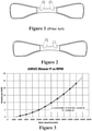
- NHF delivered through an asymmetrical cannula interface can involve making an interface in which the nasal delivery elements are of different length, internal or external diameter, or a combination of these ( Figure 2 ). Particularly for children or infants, nasal delivery elements will have a small internal diameter and thus higher resistance to gas flow.
- each nasal delivery element may have a different internal diameter (e.g., minimum internal diameter or area).
- a longer nasal delivery element may have a smaller internal diameter and higher resistance to gas flow; a shorter nasal delivery element may have a larger internal diameter (e.g., larger minimum internal diameter), hence lower resistance to gas flow at the interface.
- a decreased resistance to flow allows the desired flow to be achieved using lower backpressure, or a lower motor speed of the gas generating device, or a combination of the two.
- Asymmetrical nasal delivery elements may cause the peak expiratory pressure to decrease due to the different lengths of the nasal delivery elements at the nose which may provide different internal diameters for each nasal delivery element.
- a patient may be breathing against less pressure in the system as one nare may be open to the atmosphere, or a nasal delivery element may have a greater internal diameter compared to the other nasal delivery element or otherwise have less resistance to exhalation flow compared to the other nasal delivery element, which may reduce the pressure required to exhale.
- an asymmetrical nasal interface used with e.g., coupled via a conduit or breathing tube
- a gas generating device such as an AIRVO TM flow generator from Fisher & Paykel Healthcare Ltd.
- a gas generating device decreases the resistance to flow. This may cause the motor speed of the AIRVO TM to drop from a range of 18,000 - 22,000 RPM to a range of 14,000 - 18,000 RPM while continuing to achieve a suitable flow for the desired therapy (e.g., NHF), such as about 8 L/min.
- Figure 3 illustrates a relationship between the motor speed of the AIRVO TM flow generator and the generated backpressure in the system.
- the asymmetrical nasal delivery elements may cause a reduction of the backpressure generated in the system. As a result, if an interface is suddenly jammed into the nose, the maximum pressure generated will not exceed the backpressure in the system, which may improve the safety of the system during delivery of NHF.
- asymmetrical nasal delivery elements may reduce over-insertion of both prongs into the nares, when the nares are too small with respect to the prongs, which could result in an undesired semi-seal or seal.
- Asymmetrical flow may be delivered to the patient even if only one prong is positioned tightly in the nose.
- the asymmetrical interface improves the performance of the therapy for infants as compressed gas may be used in a system without pressure control.
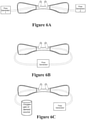
- Figures 4a - 4n show other embodiments that include but are not limited to: nasal delivery elements with the same internal or external diameter or nasal delivery elements with a different internal or external diameter ( Figure 4a and 4i ).
- the nasal delivery elements may have a different form, either different from that described above, or from each other (e.g., one prong and one nasal pillow).
- At least one nasal delivery element may be sealed ( Figures 4b and 4c ).
- At least one nasal delivery element may have at least one ventilation hole.
- the nasal delivery elements may be symmetrical with one or more ventilation holes in at least one nasal delivery element producing asymmetrical flow during breathing ( Figures 4d and 4n ).
- At least one nasal delivery element may have a narrowing at the tip, which may produce asymmetrical flow through the nasal delivery elements in a low impedance gas delivery system as a result of a pressure difference in the nose during breathing ( Figure 4j ).
- the narrowest point may be proximal to the flow source, thus the breathing cycle may not affect flow through the asymmetrical nasal delivery elements.
- the interface may be designed in a way that the left and right nasal delivery elements can be swapped.
- the interface may have an option to divert flow through either the symmetrical or asymmetrical nasal delivery elements, to an individual nasal delivery element, by varying the resistance within the interface ( Figures 4h and 4m ), or by partial over-insertion of the interface into the nose.
- the nasal delivery elements may have different lengths ( Figure 4e and 4i ), or at least one nasal delivery element may extend into the nose to the nasal valves ( Figure 4f ). More than two nasal delivery elements may be used with varying internal or external diameter or with different lengths, or a combination of these ( Figures 4g and 4k ).
- Pressure and flow may be measured and controlled in the nares simultaneously or separately.
- Flow may be continuous in one nare, while it is varied in the other nare according to the breathing cycle.
- Different interfaces, each delivering asymmetrical flow in the nose may be used to continuously deliver supplemental oxygen, and to deliver continuous or variable nasal high flow.
- One nasal delivery element may be used to deliver oxygen, gases, aerosols or the like to the patient while another nasal delivery element may be used to deliver a higher flow of air, or a different flow of oxygen, gases, aerosols or the like to the patient.
- Each nasal delivery element may supply different flow rates to the patient, and may connect to different flow generating elements ( Figures 6a - 6c ).
- the system may improve the performance of NHF therapy, particularly in the therapy delivered to infants and children. It may reduce resistance compared to existing nasal interfaces and may extend and improve functionality of respiratory devices without modification of the hardware or software.
- Asymmetrical flow useful herein can be provided by a nasal interface using any form of pressure support, such as continuous positive airway pressure (CPAP) or non-invasive therapy (NIV).
- CPAP continuous positive airway pressure
- NMV non-invasive therapy
- Anatomical dead space can be cleared by transnasal unidirectional flow during a therapy with increased airway pressure, where one nare may be sealed or may be used for inspiration from the apparatus without entrainment of room air and the other nare may be used for expiration ( Figures 4b and 4c ).
- one of the nares may be left unobstructed, providing a more comfortable therapy that has lower noise than conventional NHF therapies.
- Asymmetrical flow may occur due to a pillow, cushion, divided mask or any other sealed nasal interface ( Figures 4b and 4c ).
- One nare may be connected to the inspiratory limb of a two-limbed ventilator circuit or to a breathing tube in a one-limbed circuit, such as a CPAP blower.
- the other nare may be left open ( Figure 41), connected to conventional ventilation holes in the interface for biased flow, or connected to the expiratory limb in a two-limbed circuit ventilator. Connection to the expiratory limb of a ventilator may allow the use of flow variations to control the breathing in periodic breathing or Central Sleep Apnoea due to carbon dioxide clearance in the upper airway or re-breathing from the expiratory limb.
- Opening the mouth may decrease the pressure delivered to the patient and may improve clearance of anatomical dead space.
- a mouthpiece may be inserted to maintain the leak, and may be further connected to a negative pressure line or the expiratory limb to increase or control clearance of dead space.
- a high level of humidity such as that delivered by the devices know as AIRVO TM or ICON TM (AIRVO TM is a humidifier with integrated flow generator device and ICON TM is a CPAP device, manufactured by Fisher & Paykel Healthcare Ltd.), may be necessary to prevent drying of the nasal epithelium.
- the comfort level of temperature and dew point may be determined from a ratio, and may be, but is not limited to, a range of 33°C - 37°C and may depend on the flow rate.
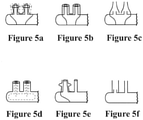
- fittings such as, but not limited to sleeves ( Figure 5a - 5c, 5e - 5f ) and inserts ( Figure 5d ), can be added to the nasal delivery elements of a nasal interface to optimise NHF therapy.
- Sleeves as described herein refer to any structure added externally to a nasal delivery element of a nasal interface.
- Inserts as described herein refer to any structure added internally into a nasal delivery element of a nasal interface.
- the NHF therapy can be improved or optimised to deliver a desired pressure profile and efficiently clear anatomical dead space.
- a nasal delivery element of a nasal interface with a smaller diameter may produce a jet with a higher velocity that may more efficiently clear patient dead space than a nasal delivery element with a larger diameter. Efficient clearance of dead space reduces the amount of carbon dioxide rebreathing that occurs ( Figure 7 ).
- a larger diameter may reduce the leak that occurs around the nasal delivery elements of the nasal interface and may result in a higher delivered pressure during both inspiration and expiration ( Figure 8 ).
- a larger diameter may be more preferable in an acute setting, particularly when a patient is suffering from respiratory distress, as a higher expiratory pressure may decrease respiratory rate and improve ventilation.
- FIG. 8 shows that a combination of a nasal delivery element with a large outer diameter and a smaller inner diameter may have similar pressure effects to a nasal delivery element with a large diameter and no insert, while a smaller inner diameter may provide less pressure. If the outer diameter is too large for a patient, the inspiratory pressure may become negative as the flow from the interface may be lower than the peak inspiratory flow.
- a nasal delivery element it generally is not desirable to increase the wall thickness of a nasal delivery element as it may be stiff in the nose of the patient, which may damage the inner surface of the nares, causing patient discomfort.
- attaching the different fittings to the interface it may be possible to benefit from the combination of the inner and outer diameters, while still providing the patient with soft nasal delivery elements to be fitted into the nares, maintaining patient comfort.
- a sleeve onto a nasal delivery element of a nasal interface ( Figures 5a - 5b, 5e - 5f )
- the inner diameter of the nasal delivery element remains the same and may allow jetting effects to efficiently clear the anatomical dead space, while the outer diameter has been increased to reduce the leak around the nasal delivery element and may produce higher pressure swings during breathing.
- the added sleeve may then be removed once the desired therapy has been delivered, or a higher pressure is no longer required.
- a sleeve may also function as a one-way valve which may inflate on expiration and increase expiratory pressure.
- a semi-permeable material may be used, a leak may be introduced, or a combination of these may be used.
- a sleeve may also be added to the interface to decrease the outer diameter so that it is smaller than the inner diameter ( Figure 5c ), which may increase jetting effects, deviate or split the flow from the centre of the nasal delivery element to the periphery, or may combine these.
- a second example is to add an insert inside the nasal delivery element ( Figure 5d ). This may decrease the inner diameter to reduce pressure and increase dead space clearance, while keeping the outer diameter the same. A smaller inner diameter increases jetting effects, deviates or splits the flow from the centre of the nasal delivery element to the periphery, or may combine the flow jetting effects with deviation or splitting of the flow from the centre of the nasal delivery element to the periphery.
- FIG. 5e a fitting that may block a nasal delivery element
- Figure 5e a fitting that may block a nasal delivery element
- Figure 5f fittings that may cause asymmetrical flow to occur
- Figure 5f a fitting that may cause asymmetrical flow to occur
- Figure 5f a fitting that may cause asymmetrical flow to occur
- Figure 5f a fitting that may cause asymmetrical flow to occur
- Figure 5f a fitting that may cause asymmetrical flow to occur
- Figure 5f asymmetrical interface symmetrical
- Adding sleeves that have been individually fit to a patient may reduce operational flow which may result in reduced noise, reduced supplemental oxygen use, improved patient comfort, and the like. Reduced operational flow may also allow less heating, water use, and the like, to be required. Only one interface is needed per patient and it can be specifically fit to the patient to vary pressure or dead space clearance.
- Figure 9 expands on embodiments described above of an asymmetrical nasal interface 100, with one nasal delivery element 200 having a greater internal cross-sectional area 205 on a plane perpendicular to the airflow direction D than the cross-sectional area 305 of other nasal delivery element 300.
- a nasal interface 100 comprises nasal delivery elements in the form of nasal prongs 200,300 of substantially similar length but different internal cross-sectional areas 205,305.
- a nasal interface 100 comprises nasal delivery elements in the form of nasal prong 300 and nasal pillow 200 of substantially similar length but different internal cross-sectional areas 205,305.
- a nasal interface 100 comprises nasal delivery elements in the form of nasal prongs 200,300 of different lengths and different internal cross-sectional areas 205,305.
- a nasal interface 100 comprises nasal delivery elements in the form of nasal prongs 200,300 of different lengths and different internal cross-sectional areas 205,305.
- a nasal interface 100 comprises nasal delivery elements in the form of nasal prongs 200,300 of substantially similar length where nasal prong 300 narrows at its tip to have a smaller internal cross-sectional area 305 than cross-sectional area 205 of nasal prong 200.
- a nasal interface 100 comprises nasal delivery elements in the form of nasal prongs 200,300 of substantially similar length but different internal cross-sectional areas 205,305, where prong 200 comprises a meshed tip comprising a plurality of smaller orifices rather than a single opening.
- a nasal interface 100 comprises nasal delivery elements in the form of orifice 200 and nasal prong 300 of different internal cross-sectional areas 205,305. It should be understood that in an alternative to the depicted embodiment, area 305 could be greater than area 205. Orifice 200 is formed in the rests adjacent a user's nare.
- a nasal interface 100 comprises nasal delivery elements in the form of nasal prongs 200,300 carried on separate gas delivery conduits, that may or may not be held together in a single patient interface.
- Prongs 200,300 are of substantially similar length but different internal cross-sectional areas 205,305.
- a nasal interface 100 comprises nasal delivery elements in the form of nasal prongs 200,300 of substantially similar length but different internal cross-sectional areas 205,305, where the length and area of prong 200 is determined by a fitting or sleeve.
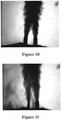
- Figures 10 and 11 are infrared photographs depicting symmetric and asymmetric flows of carbon dioxide (25 L/min).
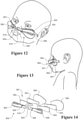
- a securement system for securing a user interface and/or user interface tubing to a patient that is useful herein is illustrated in Figures 12 to 14 , and is described in published international application WO2012/053910 .
- the securement system 500 is illustrated supporting a nasal cannula on an infant's face comprising prongs 510, a backing or harness 503 that is coupled to both prongs that retains the prongs in fixed spaced relation, and may be produced in different sizes to accommodate variations in nasal spacing.
- Backing 503 may also include housing 504 that generally encloses or captures at least a portion of the tube 501.
- the housing 504 incorporates a coupling 505 that can be used to affix headgear for retaining the interface in position.
- a pair of outriggers 506 project outwardly from the backing 503 on either side of the tube 501.
- the outriggers 506 increase a contact surface between the interface and a patient, which distributes the interface retention force over a greater area and reduces the pressure applied to a user's face.
- the user side face of the backing 503 and outriggers 506 i.e., the side that rests against the face of a user
- the backing 503 and the outriggers 506 also may be formed from a flexible material to allow the structure to adapt to a particular individual's face.
- the system provides for a generally more rapid and improved or simplified ease of installation of a user interface into an operational position on a user. Further, these benefits may also contribute to improved or simplified ease of application of alternative user interfaces or removal of a user interface from a user when cycling a user between different therapies (such as gas treatments, e.g. CPAP or high-flow applications).
- therapies such as gas treatments, e.g. CPAP or high-flow applications.
- Certain user interfaces may be provided specifically for interaction or accommodation with the system of the described embodiments.
- non-modified user interfaces can be accommodated by the described embodiments and can also be positioned relatively easily and with a minimum of time involved in an installation procedure.
- such a system may provide for quick location of an interface to a user, and may provide for the secured positioning of the interface.
- a user interface may be positioned for a user is particularly useful.
- the securement system (not independently claimed) provides for a first level of securement of a user interface to a user.
- a first level of securement may be that as shown by Figures 12 to 14 .
- a secondary level of interface securement can be utilized.
- Such an additional level may include application of an over patch, such as that provided, for example, by patch 660.
- patch 660 may be an adhesive patch and can be installed over the top of the user interface and/or tubing and adhered to a portion of the dermal patch 550.
- the securement system 500 comprises a two-part releasable attachment or connection arrangement 551.
- the releasable connection arrangement 551 acts between a pair of patches that are affixed to the patient and the user interface respectively.
- the first patch is a dermal patch 550 that is adhered or otherwise attached to the patient's skin.
- the dermal patch has a user side that faces the user's skin and an interface side that faces the user interface.
- the user side of the dermal patch 550 may be attached to the skin of a user by a dermatologically sensitive adhesive, such as a hydrocolloid.
- the user interface side of the dermal patch is provided with the first part 553 of the two-part releasable attachment or connection system 551.
- the second patch is a user interface patch 552.
- the user interface patch 552 also has a patient side and an interface side.
- the patient side of the user interface patch 552 is disposed adjacent the dermal patch when the system 500 is engaged.
- the complimentary second part of the two-part releasable attachment or connection system 553 is affixed to the patient side of the user interface patch 552, so that the respective parts of the two-part releasable attachment or connection system 551 are easily engageable when the patches 550, 552 are brought together.
- the interface side of the user interface patch 552 is affixed to the user interface.
- the user interface patch may be integrated with or suitably adhered to the user interface.
- a part or corner of the user interface patch 552 may include a region that does not attach to the dermal patch 550.
- the general purpose of this is to allow a region (or tab) that can be more easily gripped by a user or carer for removing or detaching the interface from the dermal patch.
- the backing 2004 may also comprise of such a corner region.
- the two-part releasable attachment or connection arrangement 551 may comprise a hook and loop material (such as Velcro TM hook and loop material), a magnet or an array of magnets disposed on the respective patches with the poles suitably arranged, an adhesive arrangement that is activated when the patches are urged together or another suitable releasable suitable coupling.
- the interface side of the dermal patch 550 may have one of a hook or a loop material
- the patient side of the user interface patch 552 may have the other of the hook or loop material, such that the dermal and user interface patches are releasably attachable or connectable to each other.
- the Velcro TM product range includes hook and loop product where the hook component includes upstanding nylon hooks (formed as cut loops through a woven backing web) which engage with any complimentary loop pile material.
- the Velcro TM range also includes extruded hook products, typically of a smaller size and which mate with "fluffy" non-woven fiber backing materials. These hook materials are designed to work with a range of loop substrates and in some cases, these hook materials act as loop substrates as well.
- Other similar systems include the Dual-Lock TM recloseable fastener system from 3M of St Paul, Minnesota USA.
- releasable fastening systems engage at any part of the contact between the two parts of the system. Precise alignment of individual connectors is not required because a multitude of connectors are distributed across the area of the product.
- a wide range of releasable fastener systems within this field may be used in the releasable attachment system for providing releasable attachment between the dermal patch and the user interface.
- the first part of the two-part releasable attachment or connection system may be adhered to the user interface side of the dermal patch with a suitable adhesive and occupy up to 100% or less than about 90%, or about 85%, or about 75%, or about 60% or about 50% or about 40% or about 30% or about 20% or about 10% of the interface side surface area of the dermal patch.
- the dermal patch 550 is a generally planar pad having a thickness much less than both its width and its length.
- the pad has an overall oval shape, but may take other shapes.
- the pad includes a first part 553 of the two-part releasable attachment system 551.
- the construction of the dermal patch is such that the first part 553 of the releasable attachment system comprises a substrate and multitude of fastener elements (with effective hooks, effective loops or other elements) provided across the area of the substrate.
- the substrate is secured to the body of the dermal patch. In some embodiments, the substrate is secured by adhesive or by direct bonding during forming of the dermal patch.
- the substrate is smaller in area than the dermal patch and is located on the dermal patch so that it does not reach any edge of the dermal patch. In this way, the edge of the substrate is spread from the edge of the dermal patch all around the perimeter of the substrate.
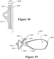
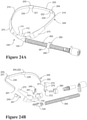
- FIGS 15 to 19 show a nasal cannula 2000 useful herein in detail, which is also described in published international application WO2012/053910 .
- the nasal cannula arrangement of figures 15 to 19 does not comprise the asymmetrical nasal delivery elements of the independent claim.
- Nasal cannula arrangement 2000 comprises at least one nasal prong 2001, modified as described above, the or each prong 2001 having a gas outlet 2002 adapted to be inserted into a user's nare (or nares) and a gas inlet 2003 fluidly connected to the gas outlet 2001.
- the at least one nasal prong 2001 comprises a backing 2004, the backing 2004 configured to rest on a user's face, and where a lip 2005 extends about at least a part of the perimeter of a rear surface 2006 of the backing 2004.
- the rear surface 2004 is configured for receiving or retaining a user interface patch 2007.
- the user interface patch 2007 may be releasably attachable or connectable to, or with, a dermal patch 2008 that is or can be affixed to a user's face.
- the rear surface 2006 can be initially provided without a user interface patch, i.e. the surface 2006 is configured to receive or retain a user interface patch 2007.
- a user interface patch 2007 may be connected to the rear surface 2006 by an adhesive or other suitable connection. Once the patch is then in position, it is ready to be connected to or receive a dermal patch.
- the user interface patch may be one part of a two-part connection system, for example the loops of a hook and loop system.
- the interface facing surface of a dermal patch 2008 would comprise of hooks that are engageable with the loops of the user interface patch. See Figure 17 illustrating rear surface 2006 retaining a user interface patch with loops ready for connection to the hooks of a dermal patch.
- Figure 18 shows a section through a cannula 2000 with the hooks 2009 of a dermal patch engaged with the loops 2010 of a user interface patch. Also shown is lumen 2011 or gas passage pathway for gas being supplied to the gas inlet of the cannula for delivery to the gas outlet 2002 of prongs 2001.
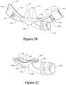
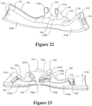
- a patient interface useful herein is shown in 20 to 23, and is described in international application PCT/NZ2014/000082 published as WO2014/182179 .
- the nasal prongs 111 and 112 are curved to extend into the patient's nares in use and to provide a smooth flow path for gases to flow through, and are modified to be asymmetric, as described above.
- the inner surfaces of the prongs 111 and 112 may be contoured to reduce noise.
- the bases of the prongs 111 and 112 may include curves surfaces to provide for smoother gases flow. This may reduce the noise level during operation.
- pads may be mounted around the base of the prongs to reduce noise.
- the pad may be a foam material or a mouldable material that generally conforms to the patient's nose anatomy. Soft cushions or pillows may alternatively be provided.
- the nasal prongs 111 and 112 are substantially hollow and substantially tubular in shape.
- the nasal prongs 111 and 112 may be consistent in outer diameter along their lengths but are preferably shaped to fit the contours of the nares.
- Each prong 111/112, where present, has an elongate opening 111a/112a at the distal end opposing a base portion 118 of the face mount part 110 to encourage a high flow of gases into the cavity.
- the nasal prongs 111 and 112 may have a tapered profile of a wider end at the base portion 118 and a narrower end at the openings 111a and 112a.
- the openings 111a and 112a may be scooped to direct the flow of gases up the patient's nares.
- the face mount portion 110 and in particular the nasal prongs 111 and 112 are preferably designed not to seal about the patient's nares to avoid excessive and potentially harmful build up of pressure during high flow therapy.
- the nasal prongs 111 and 112 are therefore sized to maintain a sufficient gap between the outer surface of the prongs 111 and 112 and the patient's skin to avoid sealing the gas path between the cannula 100 and patient. It should be understood that in the context of the present invention, the nasal prongs 111 and 112 are modified to be asymmetric, as described above.
- the face mount part 110 is shaped to generally follow the contours of a patient's face around the upper lip area.
- the face mount part 100 is moulded or pre-formed to be able to conform to and/or is pliable to adapt, accommodate and/or correspond with the contours of the user's face, in the region of the face where the cannula is to be located.
- the face mount part 110 comprises an elongate base portion 118 from which the nasal prongs 111 and 112 extend, and two wing portions 113 and 114 extending laterally from either side of the base portion 118.
- the wing portions 113 and 114 are integrally formed with the base portion 118 but may alternatively be separate parts.
- An inner side 119 of the base portion 118 of the face mount part 110 is formed with an elongated oval recess 119a configured to couple a corresponding outlet of the manifold 120.
- An arcuate bridge 118a extends from the centre of the base portion 118 to an inner wall 113a/114a of the wings to create two horizontal side entry passages 121a and 121b for insertion of the outlet 123 of the manifold 120 from either side 121a or 121b there-through.
- the gases flow manifold part 120 is generally tubular in shape having a substantially annular inlet 122 at one end, and that curves around into an elongate oval outlet 123 at the opposing end.
- the inlet 122 is preferably removably attachable to a conduit (not shown), preferably via a threaded engagement but alternatively via a snap-fit or any other type of coupling known in the art.
- the inlet is fixedly coupled or integrally formed with a conduit.
- the shape of the outlet 123 corresponds with and fits into the elongate recess 119a of the face mount part 110 with a friction fit or snap fit engagement, such that substantial force, or at least a deliberate force applied by a user or a carer, is required to separate the manifold 120 from the face mount part 110.
- the inadvertent disengagement of the manifold from the face mount part is to be avoided.
- An effective seal is also formed between the outlet 123 and the base portion 118 upon engagement of the two parts 110 and 120.
- an outer rim or lip 126 is formed about the outlet 123 which corresponds with and sealably fits into an inner groove about the periphery of the inner recess 119a to retain the outlet of the manifold 120 within the face mount part 110.
- the upper surface of the lip 126 engages an inner surface 119b of the base portion 118/surface 119b of the recess 119a to form an effective seal between the parts 110 and 120 for gases to flow there through.
- the nasal prongs 111 and 112 are aligned with corresponding apertures extending through the surface 119b of the base portion 118 to the recess 119a to fluidly connect the manifold outlet 123 with the nasal prongs 111 and 112 when coupled.
- the bridge 118a whilst defining the entry passages 121a and 121b for the manifold 120, also helps to retain the manifold 120 within the base 118 of the face mount part 110.
- a corresponding indent 128 is formed on the outer surface of the outlet 123 with opposed ridges 129a and 129b on either side to provide a push-fit engagement mechanism between the outlet 123 and the bridge 118a of the face mount part 110.
- the exterior surface of the face mount portion and/or the wings 111 and 112 may comprises one or more channels to facilitate or allow air to flow between the lip and the cannula to cool the patient.
- Adhesive pads may be provided on each wing 111 and 112 to facilitate coupling of the cannula 100 to the patient - especially for younger children (e.g. under 5 years old).
- Each wing portion 113/114 extends laterally from the base portion 118 of the face mount part 110 and comprises an outer surface 113b/114b configured to contact against the patient's face in use, preferably at least the upper lip region of the patient's face and slightly beyond towards the user's respective cheek.
- the distal ends 113c and 114c of the wings 113 and 114 are configured to releasably connect respective end portions 201 and 202 of a head strap 200, described below, to retain the face mount portion 110 against the patient's face.
- each wing 113/114 comprises an integral ridge 115/116 extending transversely along the length of the wing 113/114 from the inner side of the face mount part 110 opposing the outer surface 113b/114b of the wing 113/114.
- each ridge 115/116 is substantially perpendicular to the outer contact surface 113b/114b of the respective wing 113/114.
- Each ridge 115/116 preferably extends from the base portion 118 of the face mount part 110 and along an upper region of the respective wing 113/114.
- the ridge 115/116 acts to stabilise the face mount part 110 against the patient's face and minimise torsional stress which could otherwise cause the nasal prongs 111 and 112 to turn out and away from patient's nares.
- the dimensions of the ridge 115/116 including any combination of length, thickness and width (i.e. the extent to which the ridge extends away from the outer surface 113b/114b), should be sufficient to improve the stabilisation of the face mount part 110 upon the patient's face.
- the ridge 115/116 may be over-moulded or integrally formed with the respective wings 113/114 of the face mount part 110.
- each wing 113/114 is accentuated or formed with a substantially greater contact surface area than a contact surface area of the wing 113/114 in the region adjacent the nasal prongs.
- This distal end portion 113c/114c is preferably also angled relative to a general longitudinal axis of the face mount part 110 or base 118.
- the distal end portion 113c/114c extends obtusely away from the base 118, or from a region of the respective wing 113/114 adjacent the base, and towards the patient's respective cheek in use.
- each distal end portion 113c/114c may be angled smoothly or rounded or it may be angled sharply or abruptly relative to the remainder of the respective wing 113/114.
- the distal end portion 113c/114c is outwardly tapered to enlarge the contact surface area of the respective wing 113/114 and to also angle the distal end 113c/114c towards the patient's cheeks.
- the increased surface area at the distal ends 113c and 114c provides added real estate for forming a suitable connection mechanism to couple the head strap 200.
- clip retention formations 101 and 102 are provided at each distal end 113c/114c to releasably couple clip components of the head strap 200 to the face mount portion 110 of the cannula 100.
- a patient's septum and/or columella is generally quite a sensitive area and can be a source of discomfort when subjected to excessive contact pressure for prolonged periods.
- the present invention alleviates or reduces this pressure by providing a cushioned region of the cannula 100 adjacent the patient's septum/columella.
- the outlet 123 comprises a pair of opposed recesses or grooves 124/125 at the outer periphery for forming a dent or dip 127 in a region that locates adjacent the septum/columella in use. When coupled to the face mount portion 110, this dip 127 creates a gap between the base portion 118 and the outlet 123 of the manifold 120.
- the gap cushions/softens the region of the cannula 100 directly adjacent the septum/columella. It disengages the pressure of the harder manifold part 120 from the septum/columella and allows the septum/columella to rest on the soft base of the face mount portion 110 only.
- the base portion 118 is preferably also formed with a hollowed outer portion and/or dipped outer profile 118b between the prongs 111 and 112 to alleviate pressure at the septum/columella.
- the hollowing should be as much as possible without (significantly) compromising the flow delivered to the patient.
- the dipped portion 118b is also preferably complementary to the periphery of the outlet 123 to maintain an effective seal between the two parts of the cannula.
- an adjustable strap 200 the adjustment mechanism is provided in the form of one or more insertable/removable strap segments or strap extensions 220.
- a single strap may be provided with an adjustment mechanism comprising one or more adjustment buckles, as are well known in the art, located in a central region of the strap 200 that locates adjacent the rear of the patient's head in use, or located in regions of the strap 200 that locate to the side of the patient's head, such as near end portions 201,202.
- an adjustment mechanism comprising one or more adjustment buckles, as are well known in the art, located in a central region of the strap 200 that locates adjacent the rear of the patient's head in use, or located in regions of the strap 200 that locate to the side of the patient's head, such as near end portions 201,202.
- Strap segments 220 of a fixed length can be releasably connected to the main strap 210 to extend its length.
- the main strap 210 in this embodiment comprises a pair of intermediate or secondary end portions 203/204 that are releasably connectable with one another, and that are also releasably connectable with respective ends 221 and 222 of the strap segments 220.
- the main strap 210 is of a continuous starting length/size for the wearer. To extend the length of the strap 200 beyond this starting length, the main strap 210 can be disconnected at the secondary end portions 203/204 and one or more additional strap segments 220 are connected there between.
- a number of strap segments 220 of varying predetermined lengths may be provided to provide alternative adjustment lengths.
- one or more strap segments 220 may be provided having a length within the range of about 1cm to about 10cm, or within the range of about 2cm to about 6cm.
- the strap segments 220 have lengths of, for example, about 2cm, about 4cm or about 6cm. It will be appreciated that these examples are not intended to be limiting and the length of each strap segments can be of any size as it is dependent on the user and/or application.
- the additional strap segments are preferably formed from a soft and stretchable/elastic material such as an elastic, textile material/fabric that are comfortable to the wearer.
- a tubular knitted type head strap or sections of the head straps 210 may be utilised, particular for comfort over a user's ears.
- a head strap which is able to provide suitable locating of the patient interface in a preferred relatively stable position on a user's face, yet simultaneously provide for a relatively loose fit or low tension fit about the user's head.
- the additional strap segments may be formed from a substantially rigid material such as a hard plastics material.
- a strap connector 230 is provided at each of the secondary end portions 203/204 of the main strap 210 and the respective end portions 203/204 of the strap segments 220.
- Each connector 230 is provided with a strap connection mechanism at one end to couple to the strap material, and a coupling mechanism at an opposing end to releasably couple the respective end of a similar connector 230.
- the connector 230 may be various different forms of adjustable buckles suitable for adjusting the length or tension of the head strap sections 210 which hold the patient interface in position about a user's head.
- the connector 230 may be located so as to be off-set from a mid-point from the rear of a user's head, or may be offset to one side of a user's head. This may be advantageous so as to avoid impinging upon a part of a user's head which may otherwise be, in some positions such as sleeping, uncomfortable for the user.
- the strap segments may be of different lengths, so as to be asymmetrically provided or to help be operational with an off-set connector 230 position. Further, it may be that of the two strap segments 210, one of those straps may be adjustable in length while the other is not. For example, one strap segment 210 may be of a permanent length or permanently connected to the connector 230.
- the strap connection mechanism may comprise of a series of internal teeth located within the body of the connector for establishing a friction fit engagement with the respective end of the strap.
- a hinged jaw of the body is provided and closes upon the teeth to securely retain the end of the strap upon the teeth.
- the releasable coupling mechanism at the other end comprises a pair of male and female members, such as a protrusion and aperture respectively, both adapted to connect to corresponding male and female members of a similar connector 230.
- a lug on the protrusion may couple a recess in the female member to provide a snap-fit engagement between the members.
- any other suitable connector configuration may be used to releasably connect the secondary end portions of the strap to one another, and to the end portions of the additional strap segments.
- Cannula connectors 240 are provided at the primary end portions 201 and 202 of the main strap 210. These connectors 240 have a similar strap connection mechanism to the strap connectors 230 of the secondary end portions 203 and 204, but include a clip member, such as a push fit clip 241, at an end of the connector 240 opposing the strap ends.
- the clip 241 is configured to releasably couple the respective formation 101/102 at the side of the cannula 110.
- the clip member 241 is preferably a bendable part, such as a plastic part, that forms a hinged portion relative to the strap.
- the clip 241 is preferably preformed to have a curved shape along its length, such as one with an angle between flat and 20 degrees for example. This curve allows the clip 241 to fit the contour of the patient's face in the region of the clip 241.
- Sleeve 270 may be preformed to have a curved shape along its length, such as one with an angle between flat and 20 degrees for example. The curve allows the sleeve to fit the contour of the patient's face or cheek in the region of the sleeve in use. Alternatively the sleeve 270 may take on the shape of a curved sleeve upon engagement with the primary end portion 201/202 or connector 240 of the head strap 200.
- the sleeve 270 provides a surface region of relatively higher frictional surface material for frictionally engaging with the user's face or facial skin. This surface region is to be positioned for frictional engagement with the facial cheek skin of a user. The surface region is at least localised to the strap or the section of strap which is to be positioned upon the cheeks of a user.
- the surface region provided with the relatively higher frictional surface material is preferably of a material that is smooth and comfortable on the skin of the patient.
- the sleeve 270 or at least the surface region 271 is therefore formed from a relatively softer material than the connector 240.
- the surface region 271 or the sleeve 270 is formed from a soft Thermoplastic Elastomer (TPE), but may alternatively be formed from another plastics material such as Silicone, or any other biocompatible materials.
- TPE Thermoplastic Elastomer
- the surface region 271 may be a surface of wider surface area more adjacent to the patient interface than the surface area more distant from the patient interface.
- the sleeve 270 tapers from a relatively wider surface area 273 to a relatively lesser surface area 274 in a direction extending away from a connection point between the connector 240 and the patient interface 100.
- the width of the sleeve at the end 273 is preferably the same or similar to the width of the tapered distal end 113c/114c of the corresponding wing portion 113/114 of the face mount part 110. This provides a smooth transition between the patient interface 100 and the headgear 200 for improving aesthetics and achieving a visually appealing effect.
- Headgear for other forms of interface in addition to nasal cannula may comprise cheek supports 270 as described or similar, at or adjacent either side end of straps of headgear of the interface, which connect to the mask, for frictionally engaging with the user's face to stabilise the mask on the face at the cheeks, and particularly for example direct nasal masks comprising nozzles or pillows which enter or engage the nares of the wearer.
- Such headgear may again comprise a single head strap adapted to extend in use along the patient's cheeks, above the ears and about the back of the head, with ends comprising clips in any suitable form which couple to the mask on either side (or are permanently attached to the mask).
- Patient interfaces according to the embodiments described above may be employed in a method a method of delivering gas to the airway of a subject in need thereof, improving the ventilation of a subject in need thereof, reducing the volume of anatomical dead space within the volume of the airway of a subject in need thereof, and/or treating a respiratory condition in a subject in need thereof, as described above.
- the method is not independently claimed herein.
- the invention may also be said broadly to consist in the parts, elements and features referred to or indicated in the specification of the application, individually or collectively, in any or all combinations of two or more of said parts, elements or features.
Description
- The present invention generally relates to a nasal interface. More particularly, the present invention relates to asymmetrical nasal delivery elements for a nasal interface and other arrangements for achieving asymmetric flow or partial unidirectional flow.
- Humidifiers are used to provide humidified respiratory gases to a patient. Gases are delivered to the patient via a patient interface. Examples of a patient interface include an oral mask, a nasal mask, a nasal cannula, a combination of oral and nasal mask, and the like.
- Nasal interfaces can be used to deliver a high flow of gases to a patient. Nasal delivery elements are inserted into the nose of a patient to deliver the required therapy. The nasal delivery elements may be required to seal or semi-seal at the nose, or may not be required to seal at the nose, to deliver the therapy. Nasal high flow typically is a non-sealing therapy that delivers relatively high-volume flow to the patient through a nasal interface, which flow may be sufficient to meet or exceed the patient's inspiratory flow rate. A nasal prong interface comprising asymmetrical prongs particularly useful for patients with substantially asymmetrical and/or deformed nose shapes is disclosed in
GB2493520 - Although prongs for nasal interfaces exist in the prior art, an aspect of at least one of the embodiments disclosed herein includes the realization that there are problems with the insertion of these prior art prongs into the nose of a patient. Prongs in the art require high motor speeds of the flow generating device to deliver the desired flow rate to the patient. A flow generating device is a device that delivers a flow of gas to a patient.
- If the interface is suddenly occluded, the static pressure may increase to equal the backpressure in the system, which may potentially reach undesirable levels. The undesirably high static pressure is intensified for child and infant prongs because the reduced prong diameter required to fit the nares of a child or infant can increase resistance to flow through the interface to the patient.
- Currently there are few different sized nasal delivery elements available to better fit a patient, and it can be difficult to optimise dead space clearance and delivered pressure to the patient. The current options may use supplemental oxygen, require more heating, more water and may not provide a high level of patient comfort. Undesirably high flows or excessively high flows are being provided to patients to achieve the desired pressure effects with the existing interfaces. A nasal delivery element of a nasal interface with a smaller diameter may have a high leak and as a result will deliver lower pressure to a patient. A large diameter may not be as efficient at clearing anatomical dead space from the patient airways.
- A system is disclosed that uses nasal high flow in combination with asymmetrical nasal delivery elements for a nasal interface to deliver respiratory gases to a patient via an asymmetrical flow. Asymmetrical nasal delivery elements can provide the patient with increased dead space clearance in the upper airways. Due to a decrease in peak expiratory pressure, noise can be reduced, and asymmetrical nasal delivery elements may provide a more desirable therapy for infant use due to mitigation of the risk of completely sealing the airways of the patient. The asymmetry of the nasal delivery elements can reduce the resistance to flow through the interface, which can achieve desired flow rates using lower backpressure and/or lower motor speeds of the flow generating device.
- Different embodiments disclose a system that modifies the pressure effects during nasal high flow while maintaining efficient dead space clearance, by adding fittings such as but not limited to, sleeves or inserts to the nasal interface. It may increase pressure swings generated during breathing, increase jetting effects, improve patient comfort, more efficiently clear dead space and increase expiratory pressure. The use of fittings may reduce the required operational flow, which may result in less noise, reductions in heating, oxygen and water usage, desirable or optimised therapeutic effects of nasal high flow. Thus a lower flow rate may be able to achieve a higher pressure.
- The present invention provides a nasal interface as claimed.
- In one embodiment the present invention relates to a nasal interface comprising asymmetrical nasal delivery elements, the asymmetrical nasal delivery elements comprising a first nasal delivery element that is a prong and a second nasal delivery element that is a prong or a pillow, the prong or pillow of the second nasal delivery element having a greater internal cross-sectional area on a plane perpendicular to the airflow direction than a prong of the first nasal delivery element, which causes asymmetrical flow or partial unidirectional flow of gases at the nares of a subject, to improve dead space clearance, preferably to reduce the volume of anatomical dead space within the volume of the airway of a subject, to reduce peak expiratory pressure, to reduce noise, and/or to reduce resistance to flow at the patient interface.
- In various embodiments the first and second nasal delivery elements may comprise
- (1) an orifice without a nasal prong adapted in use to rest adjacent one nare and a nasal prong or a nasal pillow adapted in use to engage the other nare, or
- (2) a first nasal prong having a first cross-sectional area and a second nasal prong or a nasal pillow having a second cross-sectional area, the second cross-sectional area being greater than the first cross-sectional area, or
- (3) a first nasal prong having a first outer circumference and a second nasal prong or a nasal pillow having a second outer circumference, the second outer circumference being greater than the first outer circumference, or
- (4) a first nasal prong having a first cross-sectional area and a first outer circumference and a second nasal prong or a nasal pillow having a second cross-sectional area and a second outer circumference, the second cross-sectional area and second outer circumference being greater than the first cross-sectional area and first outer circumference.
- In various embodiments the second cross-sectional area may be about 1.5, 2, 2.5, 3, 3.5, 4, 4.5, 5, 5.5, 6, 6.5, 7, 7.5, 8, 8.5, 9, 9.5, 10, 10.5, 11, 11.5, 12, 12.5, 13, 13.5, 14, 14.5, 15, 15.5, 16, 16.5, 17, 17.5, 18, 18.5, 19, 19.5, 20, 20.5, 21, 21.5, 22, 22.5, 23, 23.5, 24, 24.5, 25, 25.5, 26, 26.5, 27, 27.5, 28, 28.5, 29, 29.5, 30, 30.5, 31, 31.5, 32, 32.5, 33, 33.5, 34, 34.5, 35, 35.5, 36, 36.5, 37, 37.5, 38, 38.5, 39, 39.5, 40, 40.5, 41, 41.5, 42, 42.5, 43, 43.5, 44, 44.5, 45, 45.5, 46, 46.5, 47, 47.5, 48, 48.5, 49, 49.5, or 50 mm2, and useful ranges may be selected between any of these values (for example, about 1.5 to about 10, about 1.5 to about 20, about 1.5 to about 30, about 1.5 to about 40, and about 1.5 to about 50 mm2).
- In various embodiments the first cross-sectional area may be about 20, 21, 22, 23, 24, 25, 26, 27, 28, 29, 30, 31, 32, 33, 34, 35, 36, 37, 38, 39, 40, 41, 42, 43, 44, 45, 46, 47, 48, 49, 50, 51, 52, 53, 54, 55, 56, 57, 58, 59, 60, 61, 62, 63, 64, 65, 66, 67, 68, 69, 70, 71, 72, 73, 74, 75, 76, 78, 79, or 80% of the second cross-sectional area, and useful ranges may be selected between any of these values (for example, about 20 to about 30, about 20 to about 40, about 20 to about 50, about 20 to about 60, about 20 to about 70, and about 20 to about 80%).
- In various embodiments the second cross-sectional area may be about 1.5 to about 50 mm2 and the first cross-sectional area may be about 20% to about 80% of the second cross-sectional area, preferably about 50%.
- In various embodiments the ratio of the first cross-sectional area to the second cross-sectional area may be at least about 1:1.2, 1:1.25, 1:1.3, 1:1.35, 1:1.4, 1:1.45, 1:1.5, 1:1.55, 1:1.6, 1:1.65, 1:1.7, 1:1.75, 1:1.8, 1:1.85, 1:1.9, 1:1.95, 1:2, 1:2.05, 1:2.1, 1:2.15, 1:2.2, 1:2.25, 1:2.3, 1:2.35, 1:2.4, 1:2.45, or 1:2.5, and useful ranges may be selected between any of these values (for example, about 1:1.2 to about 1:2.5). Preferably the ratio may be about 1:2.
- In various embodiments the second outer circumference may be about 7.5, 8, 8.5, 9, 9.5, 10, 10.5, 11, 11.5, 12, 12.5, 13, 13.5, 14, 14.5, 15, 15.5, 16, 16.5, 17, 17.5, 18, 18.5, 19, 19.5, 20, 20.5, 21, 21.5, 22, 22.5, 23, 23.5, 24, 24.5, 25, 25.5, 26, 26.5, 27, 27.5, 28, 28.5, 29, 29.5, or 30 mm, and useful ranges may be selected between any of these values (for example, about 7.5 to about 10, about 7.5 to about 15, about 7.5 to about 20, about 7.5 to about 25, and about 7.5 to about 30 mm).
- In various embodiments the first outer circumference may be about 20, 21, 22, 23, 24, 25, 26, 27, 28, 29, 30, 31, 32, 33, 34, 35, 36, 37, 38, 39, 40, 41, 42, 43, 44, 45, 46, 47, 48, 49, 50, 51, 52, 53, 54, 55, 56, 57, 58, 59, 60, 61, 62, 63, 64, 65, 66, 67, 68, 69, 70, 71, 72, 73, 74, 75, 76, 78, 79, or 80% of the second outer circumference, and useful ranges may be selected between any of these values (for example, about 20 to about 30, about 20 to about 40, about 20 to about 50, about 20 to about 60, about 20 to about 70, and about 20 to about 80%).
- In various embodiments the second outer circumference may be about 7.5 mm to about 30 mm and the first outer circumference may be about 20% to about 80% of the second outer circumference, preferably about 50%.
- In various embodiments the ratio of the first outer circumference to the second outer circumference may be at least about 1:1.2, 1:1.25, 1:1.3, 1:1.35, 1:1.4, 1:1.45, 1:1.5, 1:1.55, 1:1.6, 1:1.65, 1:1.7, 1:1.75, 1:1.8, 1:1.85, 1:1.9, 1:1.95, 1:2, 1:2.05, 1:2.1, 1:2.15, 1:2.2, 1:2.25, 1:2.3, 1:2.35, 1:2.4, 1:2.45, or 1:2.5, and useful ranges may be selected between any of these values (for example, about 1:1.2 to about 1:2.5). Preferably the ratio may be about 1:2.
- In various embodiments, the nasal interface may be adapted so that fittings may be attached to the nasal delivery elements of the interface to alter the shape or inner or outer diameters of the nasal delivery elements to efficiently clear dead space, reduce operational flow, and reduce noise.
- In various embodiments, one nasal delivery element may comprise a single lumen, or both nasal delivery elements may comprise a single lumen.
- Also disclosed herein, but not independently claimed, is a user interface assembly comprising a nasal interface as described herein, a securement system for the user interface and/or a component associated with the user interface (e.g. such as a tube or tubing), and/or a tube connected to the user interface providing at least a part of a breathing circuit for a user of the interface.
- In various embodiments the securement system may comprise a two-part releasable attachment (or connection) arrangement, the arrangement comprising a dermal patch and a user interface patch,
- (1) the dermal patch having a patient side and an interface side,
- (a) the patient side of the dermal patch being attachable to the skin of a user, (e.g. by an adhesive, generally being of a dermatologically sensitive adhesive such as a hydrocolloid),
- (b) the interface side of the dermal patch being provided with the first part of a two-part releasable attachment or connection system, and
- (2) the user interface patch having a interface side and patient side,
- (a) the patient side of the user interface patch being provided with the complimentary second part of the two-part releasable attachment or connection system,
- (b) the interface side of the user interface patch being attachable (or connectable) to the user interface and/or the component associated with the user interface (e.g. a tube or tubing).
- In various embodiments the tube comprises
- (1) a tubular body, the body defining a lumen extending between open terminal ends of the body,
- (2) an internal form enclosed within the lumen and supportive of the tubular body, and
- (3) a coating encapsulating the internal form, the coating securing the internal form to the tubular body.
- In various embodiments the interface comprises
- (1) at least one nasal prong, the prong having a gas outlet adapted to be inserted into a user's nare and a gas inlet fluidly connected to the gas outlet,
- (2) the at least one nasal prong comprising a backing, the backing configured to rest on a user's face, wherein a lip extends about at least a part of the perimeter of a rear surface of the backing, the rear surface configured for receiving or retaining the user interface patch, such that in use, the user interface patch may be releasably attachable or connectable to, or with, the dermal patch affixed to a user's face.
- In various embodiments the lip is a barrier.
- In various embodiments the lip is deformable.
- In various embodiments the lip extends at least about the perimeter of a region substantially adjacent to a prong associated with the backing.
- In various embodiments the lip is an endless lip extending about the perimeter of the rear surface of the backing.
- In various embodiments the lip is a series of one or more separate lips.
- In various embodiments the one or more separate lips are adjacent or adjoining or overlapping lip portions.
- In various embodiments, in use, the lip substantially forms a fluid (e.g. liquid) seal, or barrier to fluid, between the rear surface of the backing and a cannula facing surface of the user interface patch.
- In various embodiments the backing is substantially planar or flat or contoured (such as a pre-formed curve) backing configured to rest on a user's face.
- In various embodiments the backing assists as a stabilizer of the prong(s) in the nare(s) of a user.
- In various embodiments the at least one backing extends laterally outward from the at least one nasal prong, away from the septum of a user.
- In various embodiments the lip(s) is hydrophobic.
- In various embodiments the lip(s) comprises at least one outer perimeter lip portion and at least one inner perimeter lip portion, each of said lips provided for contacting with a user's face.
- In various embodiments the nasal interface may further comprise
- (1) a face mount part comprising a base portion and the nasal delivery elements, and
- (2) a gases flow manifold part having a gases inlet for receiving a flow of gas from a gas source, and a gases outlet for delivering the flow of gas to the nasal delivery elements of the face mount part, the manifold part being adapted to be received by the base portion of the face mount part to fluidly connect the outlet of the manifold with the nasal delivery elements of the face mount part, and wherein the manifold part further comprises a groove at the outlet to establish a gap between the base portion of the face mount part and the manifold part in a region of the base portion configured to locate adjacent a user's philtrum in use to thereby eliminate or at least alleviate pressure on the user's septum from the manifold part in use.
- In various embodiments the face mount part may comprise at least one substantially horizontal side entry passage to the interior of the base portion for releasably receiving the outlet of the manifold part therethrough.
- In various embodiments the face mount part may comprise a pair of opposed side entry passages to the interior of the base portion, each adapted to releasably receive the outlet of the manifold part therethrough.
- In various embodiments the gases flow manifold part may be formed from a relatively harder material than the face mount part.
- In various embodiments the gases flow manifold part may be formed from a substantially rigid plastics material, such as polycarbonate.
- In various embodiments the face mount part may be formed from a substantially soft plastics material, such as silicone.
- In various embodiments the nasal interface may further comprise headgear comprising a strap forming a part of the headgear for assisting in retaining or stabilising of the nasal interface upon a user, wherein the strap, or a section of the strap, to be located upon or to be placed in contact with the face or a portion of a user's face includes a surface region for frictionally engaging with the user's face, the surface region being of a relatively higher frictional surface material than the remainder of the strap forming the or a part of the headgear.
- In various embodiments the strap or a respective section of the strap, includes two symmetric surface regions for frictionally engaging with two symmetric portions on either side of the user's face.
- In various embodiments a remainder of the strap is arranged to extend as a non-facial contacting strap or section of strap which is to extend beyond the user's face or the portion of the user's face.
- In various embodiments, each surface region for frictionally engaging with the user's face or a portion of the user's face including the relatively higher frictional surface material assists with retaining or stabilising of a patient interface upon the face of a user.
- In various embodiments each surface region comprises a material applied to the strap or the respective section of strap.
- In various embodiments the material applied is in the form of a sleeve positioned about the strap or the respective section of strap.
- In various embodiments the sleeve is configured to removeably couple about the strap or the section of the strap.
- In various embodiments the strap or the respective section of the strap extends through a passage in the sleeve.
- In various embodiments the strap or the respective section of the strap is adapted to be threaded through the passage.
- In various embodiments the material applied is in the form of a material coated upon the strap or the respective section of strap.
- In various embodiments the material applied is over-moulded upon the strap or the respective section of strap.
- In various embodiments the material applied is smooth and comfortable for skin contact.
- In various embodiments the material applied is a thermoplastic elastomer.
- In various embodiments each surface region is a surface of wider surface area at an end to be located more adjacent to the patient interface than the surface area of an opposing end more distant from the patient interface.
- In various embodiments each surface region tapers from the relatively wider surface area to the relatively lesser surface area.
- In various embodiments the strap or each section of the strap including the surface region further comprises a component of the strap configured to releasably couple the patient interface.
- In various embodiments each portion of the user's face includes a cheek of the user.
- Also disclosed, but not independently claimed, is a method of delivering gas to the airway of a subject in need thereof, improving the ventilation of a subject in need thereof, reducing the volume of anatomical dead space within the volume of the airway of a subject in need thereof, and/or treating a respiratory condition in a subject in need thereof, the method comprising delivering a continuous flow of gas to the nares of a subject through a nasal interface comprising asymmetrical nasal delivery elements to generate an asymmetrical flow or a partial unidirectional flow of gases at the nares.
- The method may comprise improving the ventilation of a subject in need thereof includes reducing peak expiratory pressure, reducing noise during expiration, and/or reducing resistance to flow at the patient interface.
- The gas may be delivered to one nare of the subject at a first flow rate of about 5, 10, 15, 20, 25, 30, 35, 40, 45, 50, 55, or 60 L/min, and useful ranges may be selected between any of these values (for example, about 5 to about 10, about 5 to about 20, about 5 to about 30, about 5 to about 40, about 5 to about 50, and about 5 to about 60 L/min).
- The flow rate to the other nare of the subject may be at a second flow rate that may be about 20, 21, 22, 23, 24, 25, 26, 27, 28, 29, 30, 31, 32, 33, 34, 35, 36, 37, 38, 39, 40, 41, 42, 43, 44, 45, 46, 47, 48, 49, 50, 51, 52, 53, 54, 55, 56, 57, 58, 59, 60, 61, 62, 63, 64, 65, 66, 67, 68, 69, 70, 71, 72, 73, 74, 75, 76, 78, 79, or 80% of the first flow rate, and useful ranges may be selected between any of these values (for example, about 20 to about 30, about 20 to about 40, about 20 to about 50, about 20 to about 60, about 20 to about 70, and about 20 to about 80%).
- The gas may be delivered to one nare of the subject at a first flow rate of about 5 L/min to about 60 L/min and to the other nare of the subject at a second flow rate that may be about 20% to about 80% of the first flow rate, preferably about 50%.
- The subject's mouth may be closed or sealed.
- The subject's mouth may be open.
- The method (not independently claimed) may further comprise inserting a mouthpiece into the mouth of the subject, to maintain a leak from the mouth of the subject into the atmosphere, a negative pressure line, or an expiratory limb, or to increase or control dead space clearance.
- Sound generated by the expiration of gas through the nares may be less than the sound generated by nasal expiration during nasal high flow therapy conducted at an equivalent flow rate using a nasal interface that comprises symmetrical nasal delivery elements.
- The gas pressure in the subject's airway may be estimated and/or measured.
- Tthe average gas pressure in the subject's airway may be maintained at a level of less than about 4 cm H2O, preferably at a level of less than about 3.5, 3, 2.5, 5 or 1 cm H2O, preferably with the subject's mouth open or closed, preferably with the subject's mouth closed.
- The oxygen concentration of the subject's airway may be measured.
- The oxygen concentration of the subject's airway may be maintained at a substantially constant level or increased.
- The carbon dioxide concentration of the subject's airway may be measured.
- The carbon dioxide concentration of the subject's airway may be maintained at a substantially constant level or reduced.
- The molar fraction of carbon dioxide in the upper airway of the subject may be reduced, preferably by at least about 1, 2, 3, 4, 5, 6, 7, 8, 9, or 10 molar % or more, compared to the molar fraction of carbon dioxide in the upper airway of the subject when breathing without assistance.
- The molar fraction of carbon dioxide in the upper airway of the subject may be reduced, preferably by at least about 1, 2, 3, 4, 5, 6, 7, 8, 9, or 10 molar % or more, compared to nasal high flow therapy conducted at an equivalent flow rate using a nasal interface that comprises symmetrical nasal delivery elements.
- The peripheral capillary oxygen saturation of the subject may be measured.
- The peripheral capillary oxygen saturation of the subject may be maintained at a substantially constant level or increased.
- The peripheral capillary oxygen saturation of the subject may be increased compared to nasal high flow therapy conducted at an equivalent flow rate using a nasal interface that comprises symmetrical nasal delivery elements.
- The subject may be hypoxic or hypoxemic before the method is carried out.
- The respiratory condition may be chronic obstructive pulmonary disease, asthma, pneumonia, bronchitis, or emphysema.
- The gas may be delivered to the airway of the subject for at least about 15, 20, 25, 30, 35, 40, 45, 50, 55, 60, 90, 120, 150, or 180 minutes or more, or for at least about 1, 2, 3, 6, 9, 12, 15, 18, 21, 24, 36, 48, 60, or 72 hours or more, or for at least about 1, 2, 3, 4, 5, 6, or 7 days or more, and useful ranges may be selected between any of these values (for example, about 15 minutes to about 7 days, about 15 minutes to about 72 hours, about 15 minutes to about 180 minutes, about 30 minutes to about 7 days, about 30 minutes to about 72 hours, and about 30 minutes to about 180 minutes).
- The method may be carried out using an interface of the invention.
- These and other features, aspects, and advantages of the present invention will be described with respect to the following figures, which are intended to illustrate and not to limit the preferred embodiments.
-
Figure 1 is a nasal interface as known in the prior art. -
Figure 2 is a nasal interface with asymmetrical nasal delivery elements. -
Figure 3 is a graphical depiction of pressure and motor speed. -
Figures 4a - 4n are different embodiments of a nasal interface with asymmetrical nasal delivery elements. -
Figures 5a - 5f are different embodiments of a nasal interface with fittings. -
Figure 6a - 6c are different embodiments of a nasal interface with different flow supplies. -
Figure 7 depicts carbon dioxide rebreathing for nasal delivery elements of nasal interfaces with different inner diameters. -
Figure 8 depicts pressure effects for elements of nasal interfaces with different outer diameters. -
Figures 9A - 9I are different embodiments of an asymmetrical nasal interface, with one nasal delivery element having a greater internal cross-sectional area on a plane perpendicular to the airflow direction than the other nasal delivery element. -
Figure 10 is an infrared image of a symmetric carbon dioxide gas stream at a flow rate of 25 L/min. -
Figure 11 is an infrared image of an asymmetric carbon dioxide gas stream at a flow rate of 25 L/min. -
Figure 12 shows a nasal cannula positioned in an operative position on the face of a user. -
Figure 13 is a side view of the nasal cannula arrangement ofFigure 12 . -
Figure 14 shows the constituent assembly components of the embodiment ofFigures 12 and 13 . -
Figure 15 is a front perspective view of a nasal cannula arrangement with a backing component comprising a lip. The nasal cannula arrangement does not comprise the asymmetrical nasal delivery elements of the independent claim. -
Figure 16 is a rear perspective view of a nasal cannula arrangement with a backing component comprising a lip. The nasal cannula arrangement does not comprise the asymmetrical nasal delivery elements of the independent claim. -
Figure 17 is a top rear perspective view of a nasal cannula arrangement with a backing component comprising a lip and a user interface patch on a rear surface of the backing component. The nasal cannula arrangement does not comprise the asymmetrical nasal delivery elements of the independent claim. -
Figure 18 is a cross sectional view through the nasal cannula arrangement of figure 32 when user interface patch is in connection with a dermal patch. The nasal cannula arrangement does not comprise the asymmetrical nasal delivery elements of the independent claim. -
Figure 19 is a side rear perspective view of the nasal cannula arrangement ofFigures 15 to 18 . The nasal cannula arrangement does not comprise the asymmetrical nasal delivery elements of the independent claim. -
Figure 20 is a perspective view of a face mount part of the preferred form patient interface of the invention from the outer side of the face mount part. -
Figure 21 is a perspective view of a gases flow manifold part of the preferred form patient interface of the invention. -
Figure 22 is a perspective view of the face mount part ofFigure 20 from an inner side of the face mount part. -
Figure 23 is a perspective view of the face mount part ofFigure 20 from an underside of the face mount part. -
Figure 24 is a perspective view of a preferred form patient interface and headgear in (A) an assembled state, and (B) a disassembled state. - Nasal interfaces (
Figure 1 ) can be used to deliver a high flow of gases to a patient. Nasal delivery elements, such as prongs or nasal pillows, are inserted into the nose of a patient to deliver the required therapy. The nasal delivery elements may be desired to seal or semi-seal at the nose, or may not be required to seal at the nose, to deliver the therapy. As used herein, prongs typically refer to nasal delivery elements designed to not seal or to only semi-seal at the nose, while nasal pillows typically refer to nasal delivery elements designed to seal at the nose. Nasal high flow (NHF) typically is a non-sealing therapy that delivers relatively high-volume flow to the patient through a patient interface, such as a nasal interface. A nasal interface as herein described may refer to, but is not limited to, a nasal cannula. - Disclosed is a system to deliver gases to a patient through an asymmetrical cannula interface (
Figure 2 ). An asymmetrical interface or asymmetrical nasal delivery elements, as described herein, refers to a interface where the nasal delivery elements differ in length (including the substantial or complete absence of a nasal delivery element), internal or external diameter, angle or form, or any combination of these. The system allows an asymmetrical flow to be delivered through the interface to both nares or to either nare. Asymmetrical flow as described herein refers to a flow that differs within the interface or within the nose. In this way, a different flow may be delivered by each nasal delivery element, or the flow may differ between inspiration and expiration, or the delivered flow may be a combination of the above. An asymmetrical flow may also include partial unidirectional flow. Delivery of asymmetrical flow may improve clearance of dead space in the upper airways, decrease peak expiratory pressure, increase safety of the therapy particularly for children and infants, and reduce resistance to flow in the interface. An asymmetrical interface, nasal delivery elements or interface as described herein includes interfaces or systems configured to produce such asymmetrical flow through asymmetrical nasal delivery elements or otherwise. - Pressure generated by NHF depends on flow through the cannula interface, the size of the nasal delivery elements and/or nares of the patient, and the breathing cycle. If flow, leak, or a combination of flow and leak, is asymmetrical through the interface, the flow through the nose may become asymmetrical during breathing. Partial or total unidirectional flow may occur and there may be improved clearance of anatomical dead space as the air is continuously flushed from the upper airways. Total unidirectional flow may be discomforting to a subject. Partial unidirectional flow may be preferred whereby less discomfort is experienced by a subject. Total unidirectional flow as described herein occurs if flow enters one nare by a nasal delivery element and exits via the other nare via a nasal delivery element, vents to the atmosphere, due to the absence of a nasal delivery element, or the like. Partial unidirectional flow as described herein refers to flow that may enter the nose via both nares and leave the nose from one nare, flow that may enter the nose through one nare and leave the nose via both nares, or different proportions of flow that may enter the nose through both nares and different proportions of flow that may leave the nose through both nares, and is preferably flow that may enter the nose via both nares and leave the nose from one or both nares.
- NHF delivered through an asymmetrical cannula interface can involve making an interface in which the nasal delivery elements are of different length, internal or external diameter, or a combination of these (
Figure 2 ). Particularly for children or infants, nasal delivery elements will have a small internal diameter and thus higher resistance to gas flow. By using nasal delivery elements that are different lengths, each nasal delivery element may have a different internal diameter (e.g., minimum internal diameter or area). A longer nasal delivery element may have a smaller internal diameter and higher resistance to gas flow; a shorter nasal delivery element may have a larger internal diameter (e.g., larger minimum internal diameter), hence lower resistance to gas flow at the interface. A decreased resistance to flow allows the desired flow to be achieved using lower backpressure, or a lower motor speed of the gas generating device, or a combination of the two. - Asymmetrical nasal delivery elements may cause the peak expiratory pressure to decrease due to the different lengths of the nasal delivery elements at the nose which may provide different internal diameters for each nasal delivery element. During exhalation a patient may be breathing against less pressure in the system as one nare may be open to the atmosphere, or a nasal delivery element may have a greater internal diameter compared to the other nasal delivery element or otherwise have less resistance to exhalation flow compared to the other nasal delivery element, which may reduce the pressure required to exhale.
- In an example, an asymmetrical nasal interface used with (e.g., coupled via a conduit or breathing tube) a gas generating device, such as an AIRVO™ flow generator from Fisher & Paykel Healthcare Ltd., decreases the resistance to flow. This may cause the motor speed of the AIRVO™ to drop from a range of 18,000 - 22,000 RPM to a range of 14,000 - 18,000 RPM while continuing to achieve a suitable flow for the desired therapy (e.g., NHF), such as about 8 L/min.
Figure 3 illustrates a relationship between the motor speed of the AIRVO™ flow generator and the generated backpressure in the system. The asymmetrical nasal delivery elements may cause a reduction of the backpressure generated in the system. As a result, if an interface is suddenly jammed into the nose, the maximum pressure generated will not exceed the backpressure in the system, which may improve the safety of the system during delivery of NHF. - For a smaller patient, as in an infant or a child, use of asymmetrical nasal delivery elements may reduce over-insertion of both prongs into the nares, when the nares are too small with respect to the prongs, which could result in an undesired semi-seal or seal. Asymmetrical flow may be delivered to the patient even if only one prong is positioned tightly in the nose. The asymmetrical interface improves the performance of the therapy for infants as compressed gas may be used in a system without pressure control.
-
Figures 4a - 4n show other embodiments that include but are not limited to: nasal delivery elements with the same internal or external diameter or nasal delivery elements with a different internal or external diameter (Figure 4a and 4i ). The nasal delivery elements may have a different form, either different from that described above, or from each other (e.g., one prong and one nasal pillow). At least one nasal delivery element may be sealed (Figures 4b and 4c ). At least one nasal delivery element may have at least one ventilation hole. The nasal delivery elements may be symmetrical with one or more ventilation holes in at least one nasal delivery element producing asymmetrical flow during breathing (Figures 4d and 4n ). At least one nasal delivery element may have a narrowing at the tip, which may produce asymmetrical flow through the nasal delivery elements in a low impedance gas delivery system as a result of a pressure difference in the nose during breathing (Figure 4j ). The narrowest point may be proximal to the flow source, thus the breathing cycle may not affect flow through the asymmetrical nasal delivery elements. The interface may be designed in a way that the left and right nasal delivery elements can be swapped. The interface may have an option to divert flow through either the symmetrical or asymmetrical nasal delivery elements, to an individual nasal delivery element, by varying the resistance within the interface (Figures 4h and 4m ), or by partial over-insertion of the interface into the nose. The nasal delivery elements may have different lengths (Figure 4e and 4i ), or at least one nasal delivery element may extend into the nose to the nasal valves (Figure 4f ). More than two nasal delivery elements may be used with varying internal or external diameter or with different lengths, or a combination of these (Figures 4g and 4k ). - Pressure and flow may be measured and controlled in the nares simultaneously or separately. Flow may be continuous in one nare, while it is varied in the other nare according to the breathing cycle. Different interfaces, each delivering asymmetrical flow in the nose, may be used to continuously deliver supplemental oxygen, and to deliver continuous or variable nasal high flow. One nasal delivery element may be used to deliver oxygen, gases, aerosols or the like to the patient while another nasal delivery element may be used to deliver a higher flow of air, or a different flow of oxygen, gases, aerosols or the like to the patient. Each nasal delivery element may supply different flow rates to the patient, and may connect to different flow generating elements (
Figures 6a - 6c ). - The system may improve the performance of NHF therapy, particularly in the therapy delivered to infants and children. It may reduce resistance compared to existing nasal interfaces and may extend and improve functionality of respiratory devices without modification of the hardware or software.
- Asymmetrical flow useful herein can be provided by a nasal interface using any form of pressure support, such as continuous positive airway pressure (CPAP) or non-invasive therapy (NIV). Anatomical dead space can be cleared by transnasal unidirectional flow during a therapy with increased airway pressure, where one nare may be sealed or may be used for inspiration from the apparatus without entrainment of room air and the other nare may be used for expiration (
Figures 4b and 4c ). In a different embodiment one of the nares may be left unobstructed, providing a more comfortable therapy that has lower noise than conventional NHF therapies. - Asymmetrical flow may occur due to a pillow, cushion, divided mask or any other sealed nasal interface (
Figures 4b and 4c ). One nare may be connected to the inspiratory limb of a two-limbed ventilator circuit or to a breathing tube in a one-limbed circuit, such as a CPAP blower. The other nare may be left open (Figure 41), connected to conventional ventilation holes in the interface for biased flow, or connected to the expiratory limb in a two-limbed circuit ventilator. Connection to the expiratory limb of a ventilator may allow the use of flow variations to control the breathing in periodic breathing or Central Sleep Apnoea due to carbon dioxide clearance in the upper airway or re-breathing from the expiratory limb. - Opening the mouth may decrease the pressure delivered to the patient and may improve clearance of anatomical dead space. A mouthpiece may be inserted to maintain the leak, and may be further connected to a negative pressure line or the expiratory limb to increase or control clearance of dead space.
- To achieve comfortable asymmetrical flow, a high level of humidity, such as that delivered by the devices know as AIRVO™ or ICON™ (AIRVO™ is a humidifier with integrated flow generator device and ICON™ is a CPAP device, manufactured by Fisher & Paykel Healthcare Ltd.), may be necessary to prevent drying of the nasal epithelium. The comfort level of temperature and dew point may be determined from a ratio, and may be, but is not limited to, a range of 33°C - 37°C and may depend on the flow rate.
- Different embodiments disclose a system that allows better fitting of a nasal interface into the nares of a patient. More specifically, fittings such as, but not limited to sleeves (
Figure 5a - 5c, 5e - 5f ) and inserts (Figure 5d ), can be added to the nasal delivery elements of a nasal interface to optimise NHF therapy. Sleeves as described herein refer to any structure added externally to a nasal delivery element of a nasal interface. Inserts as described herein refer to any structure added internally into a nasal delivery element of a nasal interface. - The NHF therapy can be improved or optimised to deliver a desired pressure profile and efficiently clear anatomical dead space. A nasal delivery element of a nasal interface with a smaller diameter may produce a jet with a higher velocity that may more efficiently clear patient dead space than a nasal delivery element with a larger diameter. Efficient clearance of dead space reduces the amount of carbon dioxide rebreathing that occurs (
Figure 7 ). However a larger diameter may reduce the leak that occurs around the nasal delivery elements of the nasal interface and may result in a higher delivered pressure during both inspiration and expiration (Figure 8 ). A larger diameter may be more preferable in an acute setting, particularly when a patient is suffering from respiratory distress, as a higher expiratory pressure may decrease respiratory rate and improve ventilation. - By adding fittings to the nasal delivery elements of the nasal interface, it is possible to have nasal delivery elements which combine a smaller inner and a larger outer diameter to improve or optimise dead space clearance while maintaining a high pressure at the same flow.
Figure 8 shows that a combination of a nasal delivery element with a large outer diameter and a smaller inner diameter may have similar pressure effects to a nasal delivery element with a large diameter and no insert, while a smaller inner diameter may provide less pressure. If the outer diameter is too large for a patient, the inspiratory pressure may become negative as the flow from the interface may be lower than the peak inspiratory flow. - It generally is not desirable to increase the wall thickness of a nasal delivery element as it may be stiff in the nose of the patient, which may damage the inner surface of the nares, causing patient discomfort. However by attaching the different fittings to the interface it may be possible to benefit from the combination of the inner and outer diameters, while still providing the patient with soft nasal delivery elements to be fitted into the nares, maintaining patient comfort.
- For example, by adding a sleeve onto a nasal delivery element of a nasal interface (
Figures 5a - 5b, 5e - 5f ), the inner diameter of the nasal delivery element remains the same and may allow jetting effects to efficiently clear the anatomical dead space, while the outer diameter has been increased to reduce the leak around the nasal delivery element and may produce higher pressure swings during breathing. The added sleeve may then be removed once the desired therapy has been delivered, or a higher pressure is no longer required. A sleeve may also function as a one-way valve which may inflate on expiration and increase expiratory pressure. To inhibit or prevent condensate accumulation a semi-permeable material may be used, a leak may be introduced, or a combination of these may be used. A sleeve may also be added to the interface to decrease the outer diameter so that it is smaller than the inner diameter (Figure 5c ), which may increase jetting effects, deviate or split the flow from the centre of the nasal delivery element to the periphery, or may combine these. - A second example is to add an insert inside the nasal delivery element (
Figure 5d ). This may decrease the inner diameter to reduce pressure and increase dead space clearance, while keeping the outer diameter the same. A smaller inner diameter increases jetting effects, deviates or splits the flow from the centre of the nasal delivery element to the periphery, or may combine the flow jetting effects with deviation or splitting of the flow from the centre of the nasal delivery element to the periphery. - Other embodiments may include, using a fitting that may block a nasal delivery element (
Figure 5e ), allowing NHF to be delivered through the unblocked nasal delivery element to the patient, using fittings that may cause asymmetrical flow to occur (Figure 5e ), or that may make an asymmetrical interface symmetrical (Figure 5f ). Adding sleeves that have been individually fit to a patient may reduce operational flow which may result in reduced noise, reduced supplemental oxygen use, improved patient comfort, and the like. Reduced operational flow may also allow less heating, water use, and the like, to be required. Only one interface is needed per patient and it can be specifically fit to the patient to vary pressure or dead space clearance. -
Figure 9 expands on embodiments described above of an asymmetricalnasal interface 100, with onenasal delivery element 200 having a greater internalcross-sectional area 205 on a plane perpendicular to the airflow direction D than thecross-sectional area 305 of othernasal delivery element 300. Referring toFigure 9A , anasal interface 100 comprises nasal delivery elements in the form of nasal prongs 200,300 of substantially similar length but different internal cross-sectional areas 205,305. Referring toFigure 9B , anasal interface 100 comprises nasal delivery elements in the form ofnasal prong 300 andnasal pillow 200 of substantially similar length but different internal cross-sectional areas 205,305. Referring toFigure 9C , anasal interface 100 comprises nasal delivery elements in the form of nasal prongs 200,300 of different lengths and different internal cross-sectional areas 205,305. Referring toFigures 9C and 9D , anasal interface 100 comprises nasal delivery elements in the form of nasal prongs 200,300 of different lengths and different internal cross-sectional areas 205,305. Referring toFigure 9E , anasal interface 100 comprises nasal delivery elements in the form of nasal prongs 200,300 of substantially similar length wherenasal prong 300 narrows at its tip to have a smaller internalcross-sectional area 305 thancross-sectional area 205 ofnasal prong 200. Referring toFigure 9F , anasal interface 100 comprises nasal delivery elements in the form of nasal prongs 200,300 of substantially similar length but different internal cross-sectional areas 205,305, whereprong 200 comprises a meshed tip comprising a plurality of smaller orifices rather than a single opening. Referring toFigure 9G , anasal interface 100 comprises nasal delivery elements in the form oforifice 200 andnasal prong 300 of different internal cross-sectional areas 205,305. It should be understood that in an alternative to the depicted embodiment,area 305 could be greater thanarea 205.Orifice 200 is formed in the rests adjacent a user's nare. Referring toFigure 9H , anasal interface 100 comprises nasal delivery elements in the form of nasal prongs 200,300 carried on separate gas delivery conduits, that may or may not be held together in a single patient interface. Prongs 200,300 are of substantially similar length but different internal cross-sectional areas 205,305. Referring to Figure 91, anasal interface 100 comprises nasal delivery elements in the form of nasal prongs 200,300 of substantially similar length but different internal cross-sectional areas 205,305, where the length and area ofprong 200 is determined by a fitting or sleeve. -
Figures 10 and 11 are infrared photographs depicting symmetric and asymmetric flows of carbon dioxide (25 L/min). - A securement system for securing a user interface and/or user interface tubing to a patient that is useful herein is illustrated in
Figures 12 to 14 , and is described in published international applicationWO2012/053910 . Thesecurement system 500 is illustrated supporting a nasal cannula on an infant'sface comprising prongs 510, a backing or harness 503 that is coupled to both prongs that retains the prongs in fixed spaced relation, and may be produced in different sizes to accommodate variations in nasal spacing. Backing 503 may also includehousing 504 that generally encloses or captures at least a portion of thetube 501. Thehousing 504 incorporates acoupling 505 that can be used to affix headgear for retaining the interface in position. A pair ofoutriggers 506 project outwardly from the backing 503 on either side of thetube 501. Theoutriggers 506 increase a contact surface between the interface and a patient, which distributes the interface retention force over a greater area and reduces the pressure applied to a user's face. The user side face of thebacking 503 and outriggers 506 (i.e., the side that rests against the face of a user) may be contoured to reflect anticipated anatomical structures. Thebacking 503 and theoutriggers 506 also may be formed from a flexible material to allow the structure to adapt to a particular individual's face. - Beneficially, the system provides for a generally more rapid and improved or simplified ease of installation of a user interface into an operational position on a user. Further, these benefits may also contribute to improved or simplified ease of application of alternative user interfaces or removal of a user interface from a user when cycling a user between different therapies (such as gas treatments, e.g. CPAP or high-flow applications).
- Certain user interfaces may be provided specifically for interaction or accommodation with the system of the described embodiments. Alternatively, non-modified user interfaces can be accommodated by the described embodiments and can also be positioned relatively easily and with a minimum of time involved in an installation procedure.
- In various arrangements provided by the securement system, (not independently claimed) such a system may provide for quick location of an interface to a user, and may provide for the secured positioning of the interface.
- The ease with which a user interface may be positioned for a user is particularly useful. Providing a system whereby a carer (e.g. nurse) is able to apply the securement system with a single hand or single handedly, particularly where the interface user is an infant, is particularly advantageous.
- In addition, in another arrangement, the securement system (not independently claimed) provides for a first level of securement of a user interface to a user. For example, such a first level of securement may be that as shown by
Figures 12 to 14 . Where a user requires additional or heightened security of user interface positioning or securement, a secondary level of interface securement can be utilized. Such an additional level may include application of an over patch, such as that provided, for example, by patch 660. Such a patch 660 may be an adhesive patch and can be installed over the top of the user interface and/or tubing and adhered to a portion of thedermal patch 550. - The
securement system 500 comprises a two-part releasable attachment orconnection arrangement 551. Thereleasable connection arrangement 551 acts between a pair of patches that are affixed to the patient and the user interface respectively. - The first patch is a
dermal patch 550 that is adhered or otherwise attached to the patient's skin. The dermal patch has a user side that faces the user's skin and an interface side that faces the user interface. The user side of thedermal patch 550 may be attached to the skin of a user by a dermatologically sensitive adhesive, such as a hydrocolloid. The user interface side of the dermal patch is provided with thefirst part 553 of the two-part releasable attachment orconnection system 551. - The second patch is a
user interface patch 552. Theuser interface patch 552 also has a patient side and an interface side. The patient side of theuser interface patch 552 is disposed adjacent the dermal patch when thesystem 500 is engaged. The complimentary second part of the two-part releasable attachment orconnection system 553 is affixed to the patient side of theuser interface patch 552, so that the respective parts of the two-part releasable attachment orconnection system 551 are easily engageable when thepatches user interface patch 552 is affixed to the user interface. The user interface patch may be integrated with or suitably adhered to the user interface. - A part or corner of the
user interface patch 552 may include a region that does not attach to thedermal patch 550. The general purpose of this is to allow a region (or tab) that can be more easily gripped by a user or carer for removing or detaching the interface from the dermal patch. For example, thebacking 2004 may also comprise of such a corner region. - The two-part releasable attachment or
connection arrangement 551 may comprise a hook and loop material (such as Velcro™ hook and loop material), a magnet or an array of magnets disposed on the respective patches with the poles suitably arranged, an adhesive arrangement that is activated when the patches are urged together or another suitable releasable suitable coupling. The interface side of thedermal patch 550 may have one of a hook or a loop material, and the patient side of theuser interface patch 552 may have the other of the hook or loop material, such that the dermal and user interface patches are releasably attachable or connectable to each other. - When we refer to a hook and loop material, we mean any one of a wide variety of area type mechanical fasteners. For example, the Velcro™ product range includes hook and loop product where the hook component includes upstanding nylon hooks (formed as cut loops through a woven backing web) which engage with any complimentary loop pile material. The Velcro™ range also includes extruded hook products, typically of a smaller size and which mate with "fluffy" non-woven fiber backing materials. These hook materials are designed to work with a range of loop substrates and in some cases, these hook materials act as loop substrates as well. Other similar systems include the Dual-Lock™ recloseable fastener system from 3M of St Paul, Minnesota USA. The common feature of these releasable fastening systems is that they engage at any part of the contact between the two parts of the system. Precise alignment of individual connectors is not required because a multitude of connectors are distributed across the area of the product. A wide range of releasable fastener systems within this field may be used in the releasable attachment system for providing releasable attachment between the dermal patch and the user interface.
- The first part of the two-part releasable attachment or connection system may be adhered to the user interface side of the dermal patch with a suitable adhesive and occupy up to 100% or less than about 90%, or about 85%, or about 75%, or about 60% or about 50% or about 40% or about 30% or about 20% or about 10% of the interface side surface area of the dermal patch.
- According to some embodiments, the
dermal patch 550 is a generally planar pad having a thickness much less than both its width and its length. In some embodiments, the pad has an overall oval shape, but may take other shapes. - The pad includes a
first part 553 of the two-partreleasable attachment system 551. In some embodiments, the construction of the dermal patch is such that thefirst part 553 of the releasable attachment system comprises a substrate and multitude of fastener elements (with effective hooks, effective loops or other elements) provided across the area of the substrate. The substrate is secured to the body of the dermal patch. In some embodiments, the substrate is secured by adhesive or by direct bonding during forming of the dermal patch. - In some embodiments, the substrate is smaller in area than the dermal patch and is located on the dermal patch so that it does not reach any edge of the dermal patch. In this way, the edge of the substrate is spread from the edge of the dermal patch all around the perimeter of the substrate.
-
Figures 15 to 19 show anasal cannula 2000 useful herein in detail, which is also described in published international applicationWO2012/053910 . The nasal cannula arrangement offigures 15 to 19 does not comprise the asymmetrical nasal delivery elements of the independent claim.Nasal cannula arrangement 2000 comprises at least onenasal prong 2001, modified as described above, the or eachprong 2001 having agas outlet 2002 adapted to be inserted into a user's nare (or nares) and agas inlet 2003 fluidly connected to thegas outlet 2001. The at least onenasal prong 2001 comprises abacking 2004, thebacking 2004 configured to rest on a user's face, and where alip 2005 extends about at least a part of the perimeter of arear surface 2006 of thebacking 2004. Therear surface 2004 is configured for receiving or retaining auser interface patch 2007. In use, theuser interface patch 2007 may be releasably attachable or connectable to, or with, adermal patch 2008 that is or can be affixed to a user's face. - As shown by
Figures 16 and19 , therear surface 2006 can be initially provided without a user interface patch, i.e. thesurface 2006 is configured to receive or retain auser interface patch 2007. Such auser interface patch 2007 may be connected to therear surface 2006 by an adhesive or other suitable connection. Once the patch is then in position, it is ready to be connected to or receive a dermal patch. - In one form, the user interface patch may be one part of a two-part connection system, for example the loops of a hook and loop system. In such an instance, the interface facing surface of a
dermal patch 2008 would comprise of hooks that are engageable with the loops of the user interface patch. SeeFigure 17 illustratingrear surface 2006 retaining a user interface patch with loops ready for connection to the hooks of a dermal patch. -
Figure 18 shows a section through acannula 2000 with thehooks 2009 of a dermal patch engaged with theloops 2010 of a user interface patch. Also shown is lumen 2011 or gas passage pathway for gas being supplied to the gas inlet of the cannula for delivery to thegas outlet 2002 ofprongs 2001. - A patient interface useful herein is shown in 20 to 23, and is described in international application
PCT/NZ2014/000082 WO2014/182179 . - Referring to
Figures 20 to 23 , thenasal prongs prongs prongs - In some configurations, pads may be mounted around the base of the prongs to reduce noise. The pad may be a foam material or a mouldable material that generally conforms to the patient's nose anatomy. Soft cushions or pillows may alternatively be provided.
- The
nasal prongs nasal prongs prong 111/112, where present, has anelongate opening 111a/112a at the distal end opposing abase portion 118 of theface mount part 110 to encourage a high flow of gases into the cavity. In alternative embodiments thenasal prongs base portion 118 and a narrower end at theopenings openings face mount portion 110 and in particular thenasal prongs nasal prongs prongs cannula 100 and patient. It should be understood that in the context of the present invention, thenasal prongs - The
face mount part 110 is shaped to generally follow the contours of a patient's face around the upper lip area. Theface mount part 100 is moulded or pre-formed to be able to conform to and/or is pliable to adapt, accommodate and/or correspond with the contours of the user's face, in the region of the face where the cannula is to be located. - The
face mount part 110 comprises anelongate base portion 118 from which thenasal prongs wing portions base portion 118. Thewing portions base portion 118 but may alternatively be separate parts. Aninner side 119 of thebase portion 118 of theface mount part 110 is formed with anelongated oval recess 119a configured to couple a corresponding outlet of themanifold 120. Anarcuate bridge 118a extends from the centre of thebase portion 118 to aninner wall 113a/114a of the wings to create two horizontalside entry passages outlet 123 of the manifold 120 from eitherside - The gases flow
manifold part 120 is generally tubular in shape having a substantiallyannular inlet 122 at one end, and that curves around into an elongateoval outlet 123 at the opposing end. Theinlet 122 is preferably removably attachable to a conduit (not shown), preferably via a threaded engagement but alternatively via a snap-fit or any other type of coupling known in the art. Alternatively, the inlet is fixedly coupled or integrally formed with a conduit. The shape of theoutlet 123 corresponds with and fits into theelongate recess 119a of theface mount part 110 with a friction fit or snap fit engagement, such that substantial force, or at least a deliberate force applied by a user or a carer, is required to separate the manifold 120 from theface mount part 110. - Desirably, the inadvertent disengagement of the manifold from the face mount part is to be avoided.
- An effective seal is also formed between the
outlet 123 and thebase portion 118 upon engagement of the twoparts lip 126 is formed about theoutlet 123 which corresponds with and sealably fits into an inner groove about the periphery of theinner recess 119a to retain the outlet of the manifold 120 within theface mount part 110. Upon coupling theparts lip 126 engages aninner surface 119b of thebase portion 118/surface 119b of therecess 119a to form an effective seal between theparts nasal prongs surface 119b of thebase portion 118 to therecess 119a to fluidly connect themanifold outlet 123 with thenasal prongs bridge 118a whilst defining theentry passages base 118 of theface mount part 110. Acorresponding indent 128 is formed on the outer surface of theoutlet 123 with opposedridges outlet 123 and thebridge 118a of theface mount part 110. - The exterior surface of the face mount portion and/or the
wings - Adhesive pads may be provided on each
wing cannula 100 to the patient - especially for younger children (e.g. under 5 years old). - Each
wing portion 113/114 extends laterally from thebase portion 118 of theface mount part 110 and comprises anouter surface 113b/114b configured to contact against the patient's face in use, preferably at least the upper lip region of the patient's face and slightly beyond towards the user's respective cheek. The distal ends 113c and 114c of thewings respective end portions head strap 200, described below, to retain theface mount portion 110 against the patient's face. - In a preferred embodiment, each
wing 113/114 comprises anintegral ridge 115/116 extending transversely along the length of thewing 113/114 from the inner side of theface mount part 110 opposing theouter surface 113b/114b of thewing 113/114. In the preferred embodiment, eachridge 115/116 is substantially perpendicular to theouter contact surface 113b/114b of therespective wing 113/114. Eachridge 115/116 preferably extends from thebase portion 118 of theface mount part 110 and along an upper region of therespective wing 113/114. Theridge 115/116 acts to stabilise theface mount part 110 against the patient's face and minimise torsional stress which could otherwise cause thenasal prongs ridge 115/116 including any combination of length, thickness and width (i.e. the extent to which the ridge extends away from theouter surface 113b/114b), should be sufficient to improve the stabilisation of theface mount part 110 upon the patient's face. - The
ridge 115/116 may be over-moulded or integrally formed with therespective wings 113/114 of theface mount part 110. - In a preferred embodiment, the distal or
terminal end 113c/114c of eachwing 113/114 is accentuated or formed with a substantially greater contact surface area than a contact surface area of thewing 113/114 in the region adjacent the nasal prongs. Thisdistal end portion 113c/114c is preferably also angled relative to a general longitudinal axis of theface mount part 110 orbase 118. In particular, thedistal end portion 113c/114c extends obtusely away from thebase 118, or from a region of therespective wing 113/114 adjacent the base, and towards the patient's respective cheek in use. In this manner, connecting thehead strap 200 to thedistal end portions wings 113 and 144 and wearing theinterface 100 will create a substantially V-shaped structure that generates a force vector acting on thewings cannula 110 in the direction of the patient's cheeks. This has the effect of improving retention of thenasal prongs prongs wings headgear 200. Eachdistal end portion 113c/114c may be angled smoothly or rounded or it may be angled sharply or abruptly relative to the remainder of therespective wing 113/114. - In the preferred embodiment, the
distal end portion 113c/114c is outwardly tapered to enlarge the contact surface area of therespective wing 113/114 and to also angle thedistal end 113c/114c towards the patient's cheeks. - The increased surface area at the distal ends 113c and 114c provides added real estate for forming a suitable connection mechanism to couple the
head strap 200. In the preferred embodiment,clip retention formations distal end 113c/114c to releasably couple clip components of thehead strap 200 to theface mount portion 110 of thecannula 100. - A patient's septum and/or columella is generally quite a sensitive area and can be a source of discomfort when subjected to excessive contact pressure for prolonged periods. The present invention alleviates or reduces this pressure by providing a cushioned region of the
cannula 100 adjacent the patient's septum/columella. In the preferred embodiment, theoutlet 123 comprises a pair of opposed recesses orgrooves 124/125 at the outer periphery for forming a dent or dip 127 in a region that locates adjacent the septum/columella in use. When coupled to theface mount portion 110, thisdip 127 creates a gap between thebase portion 118 and theoutlet 123 of themanifold 120. In use, the gap cushions/softens the region of thecannula 100 directly adjacent the septum/columella. It disengages the pressure of the hardermanifold part 120 from the septum/columella and allows the septum/columella to rest on the soft base of theface mount portion 110 only. - The
base portion 118 is preferably also formed with a hollowed outer portion and/or dippedouter profile 118b between theprongs portion 118b is also preferably complementary to the periphery of theoutlet 123 to maintain an effective seal between the two parts of the cannula. - Generally, but also with reference to
Figure 24 , anadjustable strap 200 the adjustment mechanism is provided in the form of one or more insertable/removable strap segments orstrap extensions 220. - In an alternative embodiment, a single strap may be provided with an adjustment mechanism comprising one or more adjustment buckles, as are well known in the art, located in a central region of the
strap 200 that locates adjacent the rear of the patient's head in use, or located in regions of thestrap 200 that locate to the side of the patient's head, such as near end portions 201,202. -
Strap segments 220 of a fixed length can be releasably connected to themain strap 210 to extend its length. Themain strap 210 in this embodiment comprises a pair of intermediate orsecondary end portions 203/204 that are releasably connectable with one another, and that are also releasably connectable withrespective ends strap segments 220. When thesecondary end portions main strap 210 is of a continuous starting length/size for the wearer. To extend the length of thestrap 200 beyond this starting length, themain strap 210 can be disconnected at thesecondary end portions 203/204 and one or moreadditional strap segments 220 are connected there between. - A number of
strap segments 220 of varying predetermined lengths may be provided to provide alternative adjustment lengths. For example, one ormore strap segments 220 may be provided having a length within the range of about 1cm to about 10cm, or within the range of about 2cm to about 6cm. Thestrap segments 220 have lengths of, for example, about 2cm, about 4cm or about 6cm. It will be appreciated that these examples are not intended to be limiting and the length of each strap segments can be of any size as it is dependent on the user and/or application. - The additional strap segments are preferably formed from a soft and stretchable/elastic material such as an elastic, textile material/fabric that are comfortable to the wearer. For example, a tubular knitted type head strap or sections of the head straps 210 may be utilised, particular for comfort over a user's ears.
- It will be appreciated, particular comfort may be achieved from a head strap which is able to provide suitable locating of the patient interface in a preferred relatively stable position on a user's face, yet simultaneously provide for a relatively loose fit or low tension fit about the user's head.
- Alternatively, the additional strap segments may be formed from a substantially rigid material such as a hard plastics material.
- A
strap connector 230 is provided at each of thesecondary end portions 203/204 of themain strap 210 and therespective end portions 203/204 of thestrap segments 220. - Each
connector 230 is provided with a strap connection mechanism at one end to couple to the strap material, and a coupling mechanism at an opposing end to releasably couple the respective end of asimilar connector 230. - In an alternative, the
connector 230 may be various different forms of adjustable buckles suitable for adjusting the length or tension of thehead strap sections 210 which hold the patient interface in position about a user's head. - It will also be appreciated that the
connector 230 may be located so as to be off-set from a mid-point from the rear of a user's head, or may be offset to one side of a user's head. This may be advantageous so as to avoid impinging upon a part of a user's head which may otherwise be, in some positions such as sleeping, uncomfortable for the user. - In yet a further embodiment, the strap segments may be of different lengths, so as to be asymmetrically provided or to help be operational with an off-set
connector 230 position. Further, it may be that of the twostrap segments 210, one of those straps may be adjustable in length while the other is not. For example, onestrap segment 210 may be of a permanent length or permanently connected to theconnector 230. - In a preferred embodiment, the strap connection mechanism may comprise of a series of internal teeth located within the body of the connector for establishing a friction fit engagement with the respective end of the strap. A hinged jaw of the body is provided and closes upon the teeth to securely retain the end of the strap upon the teeth. The releasable coupling mechanism at the other end comprises a pair of male and female members, such as a protrusion and aperture respectively, both adapted to connect to corresponding male and female members of a
similar connector 230. A lug on the protrusion may couple a recess in the female member to provide a snap-fit engagement between the members. It will be appreciated that in alternative embodiments, any other suitable connector configuration may be used to releasably connect the secondary end portions of the strap to one another, and to the end portions of the additional strap segments. -
Cannula connectors 240 are provided at theprimary end portions main strap 210. Theseconnectors 240 have a similar strap connection mechanism to thestrap connectors 230 of thesecondary end portions fit clip 241, at an end of theconnector 240 opposing the strap ends. Theclip 241 is configured to releasably couple therespective formation 101/102 at the side of thecannula 110. Theclip member 241 is preferably a bendable part, such as a plastic part, that forms a hinged portion relative to the strap. Theclip 241 is preferably preformed to have a curved shape along its length, such as one with an angle between flat and 20 degrees for example. This curve allows theclip 241 to fit the contour of the patient's face in the region of theclip 241. -
Sleeve 270 may be preformed to have a curved shape along its length, such as one with an angle between flat and 20 degrees for example. The curve allows the sleeve to fit the contour of the patient's face or cheek in the region of the sleeve in use. Alternatively thesleeve 270 may take on the shape of a curved sleeve upon engagement with theprimary end portion 201/202 orconnector 240 of thehead strap 200. - The
sleeve 270 provides a surface region of relatively higher frictional surface material for frictionally engaging with the user's face or facial skin. This surface region is to be positioned for frictional engagement with the facial cheek skin of a user. The surface region is at least localised to the strap or the section of strap which is to be positioned upon the cheeks of a user. The surface region provided with the relatively higher frictional surface material is preferably of a material that is smooth and comfortable on the skin of the patient. Thesleeve 270 or at least thesurface region 271 is therefore formed from a relatively softer material than theconnector 240. - In one preferred embodiment, the
surface region 271 or thesleeve 270 is formed from a soft Thermoplastic Elastomer (TPE), but may alternatively be formed from another plastics material such as Silicone, or any other biocompatible materials. - The
surface region 271 may be a surface of wider surface area more adjacent to the patient interface than the surface area more distant from the patient interface. In the preferred embodiment, thesleeve 270 tapers from a relativelywider surface area 273 to a relativelylesser surface area 274 in a direction extending away from a connection point between theconnector 240 and thepatient interface 100. The width of the sleeve at theend 273 is preferably the same or similar to the width of the tapereddistal end 113c/114c of thecorresponding wing portion 113/114 of theface mount part 110. This provides a smooth transition between thepatient interface 100 and theheadgear 200 for improving aesthetics and achieving a visually appealing effect. - Headgear for other forms of interface in addition to nasal cannula may comprise cheek supports 270 as described or similar, at or adjacent either side end of straps of headgear of the interface, which connect to the mask, for frictionally engaging with the user's face to stabilise the mask on the face at the cheeks, and particularly for example direct nasal masks comprising nozzles or pillows which enter or engage the nares of the wearer. Such headgear may again comprise a single head strap adapted to extend in use along the patient's cheeks, above the ears and about the back of the head, with ends comprising clips in any suitable form which couple to the mask on either side (or are permanently attached to the mask).
- Patient interfaces according to the embodiments described above may be employed in a method a method of delivering gas to the airway of a subject in need thereof, improving the ventilation of a subject in need thereof, reducing the volume of anatomical dead space within the volume of the airway of a subject in need thereof, and/or treating a respiratory condition in a subject in need thereof, as described above. The method is not independently claimed herein.
- Unless the context clearly requires otherwise, throughout the description and the claims, the words "comprise", "comprising", and the like, are to be construed in an inclusive sense as opposed to an exclusive or exhaustive sense, that is to say, in the sense of "including, but not limited to".
- Reference to any prior art in this specification is not, and should not be taken as, an acknowledgement or any form of suggestion that that prior art forms part of the common general knowledge in the field of endeavour in any country in the world.
- The invention may also be said broadly to consist in the parts, elements and features referred to or indicated in the specification of the application, individually or collectively, in any or all combinations of two or more of said parts, elements or features.
- Where, in the foregoing description reference has been made to integers or components having known equivalents thereof, those integers are herein incorporated as if individually set forth.
- It should be noted that various changes and modifications to the presently preferred embodiments described herein will be apparent to those skilled in the art. Such changes and modifications may be made without departing from the scope of the invention and without diminishing its attendant advantages. For instance, various components may be repositioned as desired. It is therefore intended that such changes and modifications be included within the scope of the invention. Moreover, not all of the features, aspects and advantages are necessarily required to practice the present invention. Accordingly, the scope of the present invention is intended to be defined only by the claims that follow.
Claims (14)
- A nasal interface (100) for delivering a high flow of gases to a subject, the nasal interface comprising asymmetrical nasal delivery elements (200,300), the asymmetrical nasal delivery elements (200,300) comprising a first nasal delivery element (200,300) that is an orifice or a prong and a second nasal delivery element (200,300) that is a prong or a pillow, wherein the asymmetrical first and second nasal delivery elements (200,300) are sized to maintain a sufficient gap between the outer surface of the first and second nasal delivery elements (200,300) and the subject's skin to avoid sealing the gas path.
- The nasal interface (100) of claim 1 wherein the gap between the outer surface of the first and second nasal delivery elements (200,300) and the subject's skin allows asymmetrical or partial unidirectional gas flow, gas leak, or a combination of gas flow and leak.
- The nasal interface (100) of claim 1 or claim 2 wherein the first and second nasal delivery elements have different outer diameters and/or different outer circumferences.
- The nasal interface (100) of claim 1 or claim 2, the first and second nasal delivery elements (200,300) comprising:(i) an orifice without a nasal prong adapted in use to rest adjacent one nare and a nasal prong or a nasal pillow adapted in use to engage the other nare, or(ii) a first nasal prong having a first cross-sectional area and a second nasal prong or a nasal pillow having a second cross-sectional area, the second cross-sectional area being greater than the first cross-sectional area, or(iii) a first nasal prong having a first outer circumference and a second nasal prong or a nasal pillow having a second outer circumference, the second outer circumference being greater than the first outer circumference, or(iv) a first nasal prong having a first cross-sectional area and a first outer circumference and a second nasal prong or a nasal pillow having a second cross-sectional area and a second outer circumference, the second cross-sectional area and second outer circumference being greater than the first cross-sectional area and first outer circumference.
- The nasal interface of claim 4, wherein the second outer circumference is about 7.5 mm to about 30 mm and the first outer circumference is about 20% to about 80% of the second outer circumference, preferably about 50%.
- The nasal interface of claim 4 or claim 5, wherein the ratio of the first outer circumference to the second outer circumference is about 1:1.2 to about 1:2.5, preferably about 1:2.
- The nasal interface of any one of claims 1 to 6, adapted so that fittings may be attached to the nasal delivery elements of the interface to alter the shape or inner or outer diameters of the nasal delivery elements.
- The nasal interface of any one of claims 1 to 7, wherein the second nasal delivery element causes a greater peak expiratory pressure in the subject's nares compared to the first nasal delivery element when in use.
- The nasal interface of claim 4, wherein the second cross-sectional area is about 1.5 to about 50 mm2 and the first cross-sectional area is about 20% to about 80% of the second cross-sectional area, preferably about 50%.
- The nasal interface of claim 4, wherein the ratio of the first cross-sectional area to the second cross-sectional area is about 1:1.2 to about 1:2.5, preferably about 1:2.
- The nasal interface (100) of claim 1, the nasal interface comprising asymmetrical nasal delivery elements (200,300), the asymmetrical nasal delivery elements comprising a first and a second nasal prong, wherein the first and second prongs are sized to maintain a sufficient gap between the outer surfaces of the prongs and the subject's skin to avoid sealing the gas path.
- The nasal interface of claim 11 wherein the gap between the outer surface of the first and second nasal prongs and the subject's skin allows asymmetrical or partial unidirectional gas flow, gas leak, or a combination of gas flow and leak.
- The nasal interface of claim 11 or claim 12 wherein the first and second nasal prongs have different outer diameters and/or different outer circumferences.
- The nasal interface of claim 11 or claim 12, wherein(i) the first nasal prong has a first cross-sectional area and the second nasal prong has a second cross-sectional area, the second cross-sectional area being greater than the first cross-sectional area, or(ii) the first nasal prong has a first outer circumference and the second nasal prong has a second outer circumference, the second outer circumference being greater than the first outer circumference, or(iii) the first nasal prong has a first cross-sectional area and a first outer circumference, and the second nasal prong has a second cross-sectional area and a second outer circumference, the second cross-sectional area and second outer circumference being greater than the first cross-sectional area and first outer circumference.
Priority Applications (2)
| Application Number | Priority Date | Filing Date | Title |
|---|---|---|---|
| EP22158059.0A EP4035714A1 (en) | 2013-08-09 | 2014-08-08 | Asymmetrical nasal delivery elements and fittings for nasal interfaces |
| PL20183115T PL3763409T3 (en) | 2013-08-09 | 2014-08-08 | Asymmetrical nasal delivery elements and fittings for nasal interfaces |
Applications Claiming Priority (4)
| Application Number | Priority Date | Filing Date | Title |
|---|---|---|---|
| US201361864477P | 2013-08-09 | 2013-08-09 | |
| US201361870129P | 2013-08-26 | 2013-08-26 | |
| PCT/NZ2014/000163 WO2015020540A1 (en) | 2013-08-09 | 2014-08-08 | Asymmetrical nasal delivery elements and fittings for nasal interfaces |
| EP14833902.1A EP3030299B1 (en) | 2013-08-09 | 2014-08-08 | Asymmetrical nasal delivery elements and fittings for nasal interfaces |
Related Parent Applications (1)
| Application Number | Title | Priority Date | Filing Date |
|---|---|---|---|
| EP14833902.1A Division EP3030299B1 (en) | 2013-08-09 | 2014-08-08 | Asymmetrical nasal delivery elements and fittings for nasal interfaces |
Related Child Applications (1)
| Application Number | Title | Priority Date | Filing Date |
|---|---|---|---|
| EP22158059.0A Division EP4035714A1 (en) | 2013-08-09 | 2014-08-08 | Asymmetrical nasal delivery elements and fittings for nasal interfaces |
Publications (2)
| Publication Number | Publication Date |
|---|---|
| EP3763409A1 EP3763409A1 (en) | 2021-01-13 |
| EP3763409B1 true EP3763409B1 (en) | 2022-02-23 |
Family
ID=52461734
Family Applications (3)
| Application Number | Title | Priority Date | Filing Date |
|---|---|---|---|
| EP14833902.1A Active EP3030299B1 (en) | 2013-08-09 | 2014-08-08 | Asymmetrical nasal delivery elements and fittings for nasal interfaces |
| EP20183115.3A Active EP3763409B1 (en) | 2013-08-09 | 2014-08-08 | Asymmetrical nasal delivery elements and fittings for nasal interfaces |
| EP22158059.0A Pending EP4035714A1 (en) | 2013-08-09 | 2014-08-08 | Asymmetrical nasal delivery elements and fittings for nasal interfaces |
Family Applications Before (1)
| Application Number | Title | Priority Date | Filing Date |
|---|---|---|---|
| EP14833902.1A Active EP3030299B1 (en) | 2013-08-09 | 2014-08-08 | Asymmetrical nasal delivery elements and fittings for nasal interfaces |
Family Applications After (1)
| Application Number | Title | Priority Date | Filing Date |
|---|---|---|---|
| EP22158059.0A Pending EP4035714A1 (en) | 2013-08-09 | 2014-08-08 | Asymmetrical nasal delivery elements and fittings for nasal interfaces |
Country Status (5)
| Country | Link |
|---|---|
| US (3) | US10569043B2 (en) |
| EP (3) | EP3030299B1 (en) |
| ES (2) | ES2817076T3 (en) |
| PL (1) | PL3763409T3 (en) |
| WO (1) | WO2015020540A1 (en) |
Families Citing this family (35)
| Publication number | Priority date | Publication date | Assignee | Title |
|---|---|---|---|---|
| EP2113274B1 (en) | 2008-04-30 | 2016-04-27 | ResMed R&D Germany GmbH | Apparatus for controlled delivery of a breathing gas to the respiratory tracts of a user |
| NZ776389A (en) | 2008-06-05 | 2023-02-24 | ResMed Pty Ltd | Treatment of respiratory conditions |
| CN109675166B (en) | 2013-03-15 | 2022-07-01 | 费雪派克医疗保健有限公司 | Nasal cannula assemblies and related components |
| US10569043B2 (en) | 2013-08-09 | 2020-02-25 | Fisher & Paykel Healthcare Limited | Asymmetrical nasal delivery elements and fittings for nasal interfaces |
| EP4151258A1 (en) * | 2014-04-11 | 2023-03-22 | Fisher & Paykel Healthcare Limited | Gas therapy system |
| AU2015318727B2 (en) * | 2014-09-16 | 2020-06-18 | Fisher & Paykel Healthcare Limited | Headgear for a respiratory mask |
| ES2928472T3 (en) | 2014-09-19 | 2022-11-18 | Fisher & Paykel Healthcare Ltd | patient interface |
| EP3200857B1 (en) | 2014-10-03 | 2021-01-13 | AUT University | A method and apparatus for the controlled delivery of gases |
| EP4268873A3 (en) * | 2015-03-27 | 2024-02-14 | Fisher & Paykel Healthcare Limited | Patient interface and aspects thereof |
| WO2016157103A1 (en) * | 2015-03-31 | 2016-10-06 | Fisher & Paykel Healthcare Limited | Nasal cannula |
| WO2017004404A1 (en) * | 2015-06-30 | 2017-01-05 | Vapotherm, Inc. | Nasal cannula for continuous and simultaneous delivery of aerosolized medicament and high flow therapy |
| US10814090B2 (en) * | 2015-08-17 | 2020-10-27 | Jada Medical, Llc | Carbon dioxide airway adaptor |
| US9827392B2 (en) | 2016-01-18 | 2017-11-28 | Baiping Lei | Nasal breathing apparatus and method with multifunction |
| AU2017252762B2 (en) * | 2016-04-22 | 2022-04-21 | Fisher & Paykel Healthcare Limited | Patient interface and aspects thereof |
| CN211214855U (en) | 2016-06-30 | 2020-08-11 | 蒸汽热能公司 | Nasal cannula for respiratory therapy and kit for high flow therapy system |
| USD870269S1 (en) | 2016-09-14 | 2019-12-17 | Fisher & Paykel Healthcare Limited | Nasal cannula assembly |
| DE102017004224A1 (en) * | 2016-12-13 | 2018-11-08 | Drägerwerk AG & Co. KGaA | Nasal cannula for high-flow ventilation |
| WO2018209557A1 (en) * | 2017-05-16 | 2018-11-22 | 深圳市大疆创新科技有限公司 | Method and device for controlling device, and computer readable storage medium |
| EP3678721A1 (en) | 2017-09-08 | 2020-07-15 | Vapotherm, Inc. | Birfurcated cannula device |
| USD849243S1 (en) | 2017-11-21 | 2019-05-21 | Fisher & Paykel Healthcare Limited | Nasal cannula |
| USD849242S1 (en) | 2017-11-21 | 2019-05-21 | Fisher & Paykel Healthcare Limited | Nasal cannula assembly |
| USD911515S1 (en) * | 2018-03-21 | 2021-02-23 | Medin Medical Innovations Gmbh | Nasal cannula |
| US20210370003A1 (en) * | 2018-06-19 | 2021-12-02 | Fisher & Paykel Healthcare Limited | Nasal cannula and securement system |
| US10314999B1 (en) | 2018-08-23 | 2019-06-11 | Baiping Lei | Nasal breathing apparatus and method for high-flow therapy and non-invasive ventilation |
| CN109303960B (en) * | 2018-10-26 | 2020-11-03 | 北京怡和嘉业医疗科技股份有限公司 | Ventilation treatment equipment and control method |
| TW202027811A (en) * | 2018-12-10 | 2020-08-01 | 紐西蘭商費雪&佩凱爾關心健康有限公司 | Respiratory interface |
| BR112021026256A2 (en) | 2019-06-28 | 2022-03-03 | Vapotherm Inc | Variable geometry cannula |
| EP4034211B1 (en) | 2019-09-26 | 2023-12-27 | Vapotherm, Inc. | Internal cannula mounted nebulizer |
| US11925752B1 (en) * | 2019-11-03 | 2024-03-12 | Paul Diamond | Asymmetric temperature nasal breathing apparatuses and methods |
| CA3190863A1 (en) * | 2020-08-06 | 2022-02-10 | Fisher & Paykel Healthcare Limited | A patient interface and a respiratory support system |
| AU2022263728A1 (en) * | 2021-04-30 | 2023-11-02 | Fisher & Paykel Healthcare Limited | Patient interface |
| CN218165762U (en) * | 2021-04-30 | 2022-12-30 | 费雪派克医疗保健有限公司 | Nasal and patient interfaces |
| KR102613153B1 (en) * | 2021-09-24 | 2023-12-13 | 주식회사 뉴마핏 | A device for assisting to breath |
| TW202327679A (en) * | 2021-10-22 | 2023-07-16 | 紐西蘭商費雪 & 佩凱爾關心健康有限公司 | Patient interface |
| WO2023230091A1 (en) * | 2022-05-25 | 2023-11-30 | Carilion Clinic | System, devices and methods for delivering a flow of oxygen |
Family Cites Families (388)
| Publication number | Priority date | Publication date | Assignee | Title |
|---|---|---|---|---|
| US362664A (en) | 1887-05-10 | rothwell | ||
| US2735432A (en) | 1956-02-21 | hudson | ||
| US1248558A (en) | 1915-04-22 | 1917-12-04 | Leon A Scribner | Coupling. |
| US1229050A (en) | 1917-03-29 | 1917-06-05 | Robert Donald | Respirator. |
| DE472739C (en) | 1926-01-14 | 1929-03-05 | Draegerwerk Ag | Frame for the eye glasses of smoke goggles, breathing masks, gas protection masks or the like. |
| US2168705A (en) | 1938-10-29 | 1939-08-08 | Francisco Charles Henry | Nasal inhaler |
| US2245969A (en) | 1939-11-27 | 1941-06-17 | Francisco Charles Henry | Nasal inhaler |
| US2366067A (en) | 1943-06-04 | 1944-12-26 | Smith Franklin Elijah | Hose coupling |
| US2499650A (en) | 1946-10-21 | 1950-03-07 | Arthur L Kaslow | Nasal oxygen feeder and method |
| US2693800A (en) | 1951-04-27 | 1954-11-09 | Caldwell Lyle | Nasal cannula |
| GB704819A (en) | 1951-09-24 | 1954-03-03 | Ralph Edwin Darling | Oxygen-breathing hose and method of manufacture |
| US2663297A (en) | 1953-01-19 | 1953-12-22 | Harold G Belasco | Nasal adapter for oxygen inhalation |
| FR1095781A (en) | 1954-03-17 | 1955-06-06 | Snorkel and swimming mask attachment | |
| US2868199A (en) | 1955-05-20 | 1959-01-13 | Charles H Hudson | Cannula |
| US2918314A (en) | 1955-07-29 | 1959-12-22 | Gen Electric | Pipe coupling having a portion of the outer resilient tube in axial tension |
| US2902737A (en) | 1956-02-13 | 1959-09-08 | Switlik Parachute Co Inc | Quick detachable parachute harness connector |
| NL123968C (en) | 1959-09-16 | |||
| US3161199A (en) | 1962-10-31 | 1964-12-15 | Varvel R Robertson | Stomach tube holder |
| US3288136A (en) | 1964-01-07 | 1966-11-29 | Douglas W Lund | Tube lock |
| US3400196A (en) | 1964-06-30 | 1968-09-03 | Union Carbide Corp | Method for the permanent compression of a sheet of flexible polyurethane foam |
| US3510155A (en) | 1968-03-04 | 1970-05-05 | Edgar M Jacobus | Swivel fitting |
| JPS4815396Y1 (en) | 1968-07-13 | 1973-04-27 | ||
| FR1585639A (en) | 1968-08-01 | 1970-01-30 | ||
| US3570482A (en) | 1968-12-09 | 1971-03-16 | Fujiboseki Kk | Elastic surgical bandage |
| US3650867A (en) | 1969-06-25 | 1972-03-21 | Collins & Aikman Corp | Method of producing laminated textile fabrics with improved dimensional stability |
| AT290857B (en) | 1969-10-21 | 1971-06-25 | Semperit Ag | Process for the production of a laminate |
| US3702612A (en) | 1971-03-01 | 1972-11-14 | Robert M Schlesinger | Catheter support |
| US3877436A (en) | 1971-03-22 | 1975-04-15 | Hudson Oxygen Therapy Sales Co | Apparatus and method for molding a nasal cannula |
| US3682171A (en) | 1971-03-31 | 1972-08-08 | Baxter Laboratories Inc | Nasal cannula |
| US3754552A (en) | 1971-06-08 | 1973-08-28 | Sandoz Ag | Flexible nasal cannula |
| US3799164A (en) | 1971-08-12 | 1974-03-26 | Du Pont | Analgesic apparatus |
| US3858615A (en) | 1972-12-11 | 1975-01-07 | Puritan Bennett Corp | Flexible hose construction |
| GB1419841A (en) | 1973-01-06 | 1975-12-31 | Flexible Ducting Ltd | Flexible retractable tubes |
| US3972321A (en) | 1975-02-20 | 1976-08-03 | Proctor John S | Upper lip mounted retaining means for medical-surgical tubes |
| US4000341A (en) | 1975-05-23 | 1976-12-28 | Minnesota Mining And Manufacturing Company | Autoclavable, corrugated, respiratory care tubing |
| US4106505A (en) | 1977-01-17 | 1978-08-15 | Salter Labs., Inc. | Nasal cannula assembly |
| US4142527A (en) | 1977-02-07 | 1979-03-06 | Garcia Nelson C | Endotracheal tube holder |
| US4152017A (en) | 1977-08-08 | 1979-05-01 | Metatech Corporation | Swivel connector for endotracheal tube or the like |
| US4177945A (en) | 1978-03-06 | 1979-12-11 | Warner-Lambert Company | Humidifier unit |
| US4316458A (en) | 1978-05-09 | 1982-02-23 | National Research Development Corporation | Patient ventilators |
| US4248218A (en) | 1978-09-22 | 1981-02-03 | Fischer Charles M | Gas administration scavenging mask |
| US4216769A (en) | 1978-09-29 | 1980-08-12 | Grimes Jerry L | Bi-flow nasal cup |
| US4282871A (en) | 1979-01-08 | 1981-08-11 | Technalytics Inc. | Naso-gastric tube stabilizer |
| US4273124A (en) | 1979-06-01 | 1981-06-16 | Zimmerman J Earl | Nasal cannula |
| US4367735A (en) | 1979-12-31 | 1983-01-11 | Novametrix Medical Systems, Inc. | Nasal cannula |
| US4284076A (en) | 1980-05-23 | 1981-08-18 | Technalytics, Inc. | Naso-gastric tube stabilizer |
| US4328797A (en) | 1980-07-23 | 1982-05-11 | Rollins Iii Offord L | Naso-gastric oxygen mask |
| US4653542A (en) | 1980-10-02 | 1987-03-31 | The Kendall Company | Medical tubing and connector |
| US4441494A (en) | 1981-03-02 | 1984-04-10 | Montalbano Anthony | Cold weather breathing device |
| US4463755A (en) | 1981-05-18 | 1984-08-07 | Terumo Corporation | Breathing circuit |
| US4457544A (en) | 1981-08-13 | 1984-07-03 | Liquid Tight Corporation | Connector for flexible electrical conduit |
| US4422456A (en) | 1981-09-08 | 1983-12-27 | City Of Hope National Medical Center | Nasal cannula structure |
| US4454880A (en) | 1982-05-12 | 1984-06-19 | Rudolph Muto | Nasal hood with open-bottom mixing chamber |
| US4648923A (en) | 1983-12-28 | 1987-03-10 | Bernard Chapnick | Method of forming a shoe insert |
| US4586273A (en) | 1983-12-28 | 1986-05-06 | Bernard Chapnick | Shoe insert construction |
| US4676241A (en) | 1984-01-16 | 1987-06-30 | W.L.G. Technology | Ventilation tube swivel |
| FR2558731B1 (en) | 1984-01-26 | 1988-06-24 | Hertzog Christian | DEVICE FOR IMMOBILIZING NASO-TRACHEAL INTUBATION PROBES |
| US4648398A (en) | 1984-10-31 | 1987-03-10 | Sherwood Medical Company | Nasal cannula |
| JPS61228996A (en) | 1985-04-03 | 1986-10-13 | 岩崎通信機株式会社 | Control circuit for pen |
| US4832010A (en) | 1985-06-11 | 1989-05-23 | Max Lerman | Orthopedic supports and material for making same |
| US4685456A (en) | 1985-12-02 | 1987-08-11 | Mary Smart | Self-retracting oxygen tubing |
| DE3544000A1 (en) | 1985-12-13 | 1987-06-19 | Bayer Ag | STABILIZED THERMOPLASTIC MOLDS BASED ON ABS POLYMERS AND ACYLPHOSPHANOXIDES |
| US4808160A (en) | 1986-04-14 | 1989-02-28 | Timmons John W | Nasal cannula apparatus |
| JPH047772Y2 (en) | 1986-11-11 | 1992-02-28 | ||
| US4753233A (en) | 1987-02-10 | 1988-06-28 | Advantage Medical | Nasal cannula |
| US4782832A (en) | 1987-07-30 | 1988-11-08 | Puritan-Bennett Corporation | Nasal puff with adjustable sealing means |
| US4838258A (en) | 1987-10-26 | 1989-06-13 | Gibeck-Dryden Corporation | Gas sampling lumen for breathing system |
| US4913471A (en) | 1987-11-10 | 1990-04-03 | Huneke Gerald L | Swivel joint |
| EP0406258A4 (en) | 1988-03-23 | 1991-03-13 | Christa Ursula Palfy | Nasal tube holder |
| US5335656A (en) | 1988-04-15 | 1994-08-09 | Salter Laboratories | Method and apparatus for inhalation of treating gas and sampling of exhaled gas for quantitative analysis |
| US5042478A (en) | 1988-08-26 | 1991-08-27 | University Technologies International, Inc. | Method of ventilation using nares seal |
| US4919128A (en) | 1988-08-26 | 1990-04-24 | University Technologies International Inc. | Nasal adaptor device and seal |
| US4915105A (en) | 1988-10-28 | 1990-04-10 | Lee Tien Chu | Miniature respiratory apparatus |
| US5005571A (en) | 1988-11-25 | 1991-04-09 | Dietz Henry G | Mouth nose mask for use with an inhalation therapy and/or breathing monitoring apparatus |
| US4875718A (en) | 1988-12-02 | 1989-10-24 | Marken Robert E | Swivel connector for preventing kinking of flexible medical hoses |
| US4933231A (en) | 1989-02-06 | 1990-06-12 | Mcguire-Nicholas Company, Inc. | Abrasion resistant, high strength composite padded fabric material |
| US5009227A (en) | 1989-09-21 | 1991-04-23 | Nieuwstad Peter P | Endotracheal tube holder |
| US4995384A (en) | 1989-10-30 | 1991-02-26 | Keeling James L | Neck support for nasal cannula |
| US5183059A (en) | 1990-01-19 | 1993-02-02 | David Leonardi | Eye shield retention system |
| US5156641A (en) | 1990-03-07 | 1992-10-20 | Mayo Foundation For Medical Education And Research | Naso-gastric catheter anchor system |
| US5025805A (en) | 1990-07-11 | 1991-06-25 | Betty Nutter | Nasal cannula assembly |
| US5046200A (en) | 1990-08-29 | 1991-09-10 | Irving Feder | Reversible, quick-adjustable diver's face mask strap |
| US5139476A (en) | 1991-04-26 | 1992-08-18 | Camp International, Inc. | Orthotic knee wrap |
| US5221252A (en) | 1991-10-15 | 1993-06-22 | Tru-Fit Marketing Corp. | Adjustable knee support |
| US5178163A (en) | 1991-12-31 | 1993-01-12 | Yewer Jr Edward H | Support belt |
| US5222486A (en) | 1992-03-11 | 1993-06-29 | James Cromwell | Swivel connector for use in an oxygen line |
| DE9213354U1 (en) | 1992-10-05 | 1994-02-10 | Minde Andreas | Respiratory mask |
| US5308337A (en) | 1993-03-16 | 1994-05-03 | Bingisser Timothy A | Medical tube clip device |
| JP3015628B2 (en) | 1993-06-30 | 2000-03-06 | 日本プレストン株式会社 | Transfer type decorative sheet and manufacturing method thereof |
| US5400776A (en) | 1993-07-09 | 1995-03-28 | Proprietary Technology, Inc. | Apparatus for maintaining a bend in a medical insufflation tube |
| US5485850A (en) | 1993-08-13 | 1996-01-23 | Dietz; Henry G. | Monitor of low pressure intervals with control capabilities |
| JPH07127780A (en) | 1993-11-02 | 1995-05-16 | Shiro Kanao | Coupling for corrugated spiral pipe, corrugated spiral pipe with coupling, manufacture thereof, method of connecting spiral pipe to corrugated spiral pipe with coupling |
| US5429126A (en) | 1994-03-30 | 1995-07-04 | Bracken; Mary R. | Respiratory mask headset attachment |
| US5438979A (en) | 1994-06-17 | 1995-08-08 | Johnson Enterprises, Inc. | Nasal cannula support |
| US5487571A (en) | 1994-08-29 | 1996-01-30 | Robertson; Duane D. | Pipe fitting |
| US5509409A (en) | 1994-09-12 | 1996-04-23 | The Living Trust Of Marjorie F. Weatherholt | Nasal cannula assembly |
| US5507535A (en) | 1995-01-09 | 1996-04-16 | Mckamey; Floyd | Conduit swivel connector |
| US5533506A (en) | 1995-01-13 | 1996-07-09 | Medlife, Inc. | Nasal tube assembly |
| US5513635A (en) | 1995-02-02 | 1996-05-07 | Bedi; Shan | Nasal cannula anchoring apparatus |
| US6123077A (en) | 1995-03-09 | 2000-09-26 | 3M Innovative Properties Company | Flat-folded personal respiratory protection devices and processes for preparing same |
| US5724965A (en) | 1995-06-06 | 1998-03-10 | Respironics Inc. | Nasal mask |
| ZA954682B (en) * | 1995-06-07 | 1996-01-29 | Raw Robert M | Endotracheal tube |
| US5572994A (en) | 1995-06-07 | 1996-11-12 | Smith; Steven W. | Occlusion resistant oxygen supply conduit for a nasal cannula |
| AU714588B2 (en) | 1995-10-03 | 2000-01-06 | 3M Innovative Properties Company | Therapeutic elastic body support |
| US5694927A (en) | 1995-11-08 | 1997-12-09 | Bohmfalk; George L. | Disposable mask and suction catheter |
| US5704916A (en) | 1995-11-30 | 1998-01-06 | Byrd; Timothy N. | Oxygen tube support apparatus and associated method |
| US6070579A (en) | 1996-03-08 | 2000-06-06 | 3M Innovative Properties Company | Elastomeric composite headband |
| US5724677A (en) | 1996-03-08 | 1998-03-10 | Minnesota Mining And Manufacturing Company | Multi-part headband and respirator mask assembly and process for making same |
| US6219490B1 (en) | 1996-06-13 | 2001-04-17 | Mallinckrodt Inc. | Ventilation tube, particularly for medical devices |
| US5802620A (en) | 1996-09-13 | 1998-09-08 | Chiang; Herman | Swimming goggle structure |
| US5682881A (en) | 1996-10-21 | 1997-11-04 | Winthrop; Neil | Nasal CPAP/Cannula and securement apparatus |
| JP3001434B2 (en) | 1996-10-24 | 2000-01-24 | 茨城日本電気株式会社 | Rotation imbalance correction mechanism of spindle motor |
| US6019101A (en) | 1996-10-31 | 2000-02-01 | Sleepnet Corporation | Nasal air mask |
| AUPP855099A0 (en) | 1999-02-09 | 1999-03-04 | Resmed Limited | Gas delivery connection assembly |
| US6415789B1 (en) | 1997-02-03 | 2002-07-09 | Sorenson Critical Care, Inc. | Swivel structure |
| CA2280692A1 (en) | 1997-02-20 | 1998-08-27 | John Kusiak | Spirometer breathing tube |
| US5937851A (en) | 1997-02-27 | 1999-08-17 | Respironics, Inc. | Swivel device utilizing bearing clearance to allow carbon dioxide laden exhaust |
| WO1998044973A1 (en) | 1997-04-04 | 1998-10-15 | Salter Labs | Adhesive patch for securing a nasal cannula |
| US20100113956A1 (en) | 1997-04-29 | 2010-05-06 | Salter Labs | Nasal cannula for acquiring breathing information |
| US6119694A (en) | 1997-07-24 | 2000-09-19 | Respironics Georgia, Inc. | Nasal mask and headgear |
| US5934276A (en) | 1997-10-20 | 1999-08-10 | Pelabro, Inc. | Oral tube holder |
| US6386198B1 (en) | 1997-12-11 | 2002-05-14 | Florence Rugless | Multi-purpose oxygen face mask |
| US6119693A (en) | 1998-01-16 | 2000-09-19 | Resmed Limited | Forehead support for facial mask |
| US6017315A (en) | 1998-02-25 | 2000-01-25 | Respironics, Inc. | Patient monitor and method of using same |
| FR2775905B1 (en) | 1998-03-16 | 2000-08-11 | Assist Publ Hopitaux De Paris | NASAL VENTILATION MASK AND MANUFACTURING METHOD |
| US6174001B1 (en) | 1998-03-19 | 2001-01-16 | Hydril Company | Two-step, low torque wedge thread for tubular connector |
| US6328038B1 (en) | 1998-07-14 | 2001-12-11 | Fred Bruce Kessler | Nasal cannula retainer |
| US6561193B1 (en) | 1998-10-30 | 2003-05-13 | Linda J. Noble | Nasal gas delivery apparatus and a nasal vestibular airway |
| AUPQ102999A0 (en) | 1999-06-18 | 1999-07-08 | Resmed Limited | A connector for a respiratory mask and a respiratory mask |
| US6003213A (en) | 1999-01-11 | 1999-12-21 | Illinois Tool Works Inc. | Ball and socket buckle |
| US6595215B2 (en) | 2000-03-13 | 2003-07-22 | Innomed Technologies, Inc. | Ventilation interface for sleep apnea therapy |
| US6374826B1 (en) | 1999-03-18 | 2002-04-23 | Resmed Limited | Mask and headgear connector |
| DE60020568T2 (en) | 1999-03-26 | 2006-05-04 | Mallinckrodt, Inc. | UNLOCKED DEVICE FOR AIR EQUIPMENT |
| US6347631B1 (en) | 1999-11-09 | 2002-02-19 | Mallinckrodt, Inc. | Cantilever device and method for breathing devices and the like |
| WO2000059567A1 (en) | 1999-04-01 | 2000-10-12 | Breas Medical Ab | Respiratory mask and method for its manufacture |
| US6148929A (en) | 1999-05-18 | 2000-11-21 | Winters; Larry | Feeler rod for water mains |
| US6439230B1 (en) * | 1999-06-18 | 2002-08-27 | Resmed Limited | Mask with recess including at least one mask port |
| US6415788B1 (en) | 1999-07-02 | 2002-07-09 | Enternet Medical, Inc. | Apparatus for treating respiratory gases including liquid trap |
| US6318364B1 (en) | 1999-07-05 | 2001-11-20 | Be Intellectual Property, Inc. | Modular drop out container for aircraft oxygen masks |
| GB9919652D0 (en) | 1999-08-20 | 1999-10-20 | Smiths Industries Plc | Medico-surgical tube assemblies |
| US6434796B1 (en) | 1999-10-20 | 2002-08-20 | Kathryn M. Speirs | Oxygen delivery cannula retainer, cannula with retainers assembly, and method for retaining cannulas |
| AUPQ382299A0 (en) | 1999-11-03 | 1999-11-25 | Australian Centre For Advanced Medical Technology Ltd | Mask |
| WO2001066174A1 (en) | 2000-03-03 | 2001-09-13 | The Penn State Research Foundation | Nasal oral respiratory interface |
| US20010035185A1 (en) | 2000-04-26 | 2001-11-01 | Christopher Kent L. | Method and apparatus for pharyngeal augmentation of ventilation |
| BR0102116B1 (en) | 2000-05-10 | 2010-09-21 | component for a breathing circuit member. | |
| US6367510B1 (en) | 2000-06-02 | 2002-04-09 | Eric Carlson | Tubing product having a helical support bead with lumen and method |
| US6938619B1 (en) | 2000-06-13 | 2005-09-06 | Scott Laboratories, Inc. | Mask free delivery of oxygen and ventilatory monitoring |
| EP1163923B1 (en) | 2000-06-14 | 2005-11-16 | Fisher & Paykel Healthcare Limited | A nasal mask |
| AUPQ821500A0 (en) | 2000-06-19 | 2000-07-13 | Australian Centre For Advanced Medical Technology Ltd | Mask |
| JP2002000748A (en) | 2000-06-19 | 2002-01-08 | Tsubota:Kk | Mask auxiliary tool |
| AUPQ880800A0 (en) | 2000-07-17 | 2000-08-10 | Australian Centre For Advanced Medical Technology Ltd | Mask |
| JP3420186B2 (en) | 2000-08-07 | 2003-06-23 | 株式会社東京興業貿易商会 | Medical mask |
| US6679261B2 (en) | 2000-08-24 | 2004-01-20 | Resmed Limited | Forehead support for facial mask |
| US6418929B1 (en) | 2000-09-18 | 2002-07-16 | Suzanne H. Norfleet | Infant oxygen mask |
| US6418928B1 (en) | 2000-09-25 | 2002-07-16 | Mallinckrodt Inc. | Multi-seal respirator mask |
| US6508249B2 (en) | 2000-10-05 | 2003-01-21 | Vital Signs, Inc. | Connecting apparatus for placing fluid flow paths in fluid communication |
| US6431172B1 (en) | 2000-10-20 | 2002-08-13 | Mallinckrodt Inc. | Nasal cannula with inflatable plenum chamber |
| CA2440982A1 (en) | 2001-03-15 | 2002-09-26 | David George Stark | Swivel device for hoses |
| US6799575B1 (en) * | 2001-04-21 | 2004-10-05 | Aaron Carter | Cannula for the separation of inhaled and exhaled gases |
| DE20111396U1 (en) | 2001-07-12 | 2001-10-18 | Hoffrichter Medizintechnik Gmb | Respiratory therapy device |
| US7753050B2 (en) | 2001-09-07 | 2010-07-13 | Resmed Limited | Headgear connection assembly for a respiratory mask assembly |
| EP1621224A3 (en) | 2001-09-24 | 2006-04-19 | FUKUNAGA, Atsuo F. | Breathing circuit having an adjustable volume and length |
| US6796310B2 (en) | 2001-10-11 | 2004-09-28 | Venetec International, Inc. | Endo-tracheal tube securement system |
| US6779522B2 (en) | 2001-10-16 | 2004-08-24 | Perma Pure, Inc. | Method and apparatus for treating breathing gases |
| US6679265B2 (en) | 2001-10-25 | 2004-01-20 | Worldwide Medical Technologies | Nasal cannula |
| US7156097B2 (en) | 2001-11-27 | 2007-01-02 | Norman Cardoso | Nasal cannula |
| US7156127B2 (en) | 2001-12-17 | 2007-01-02 | Flexible Technologies, Inc. | Current carrying stretch hose |
| US7147252B2 (en) | 2001-12-21 | 2006-12-12 | Kimberly-Clark Worldwide, Inc. | Medical connector |
| US6505624B1 (en) | 2002-01-29 | 2003-01-14 | George Campbell, Sr. | Gas delivery system retention device and method for retaining a gas delivery system |
| WO2003066145A1 (en) | 2002-02-04 | 2003-08-14 | Fisher & Paykel Healthcare Limited | Breathing assistance apparatus |
| AU2003207984A1 (en) | 2002-02-15 | 2003-09-04 | Oridion Medical 1987 Ltd. | Dual function nasal cannula |
| EP1342484B1 (en) | 2002-03-06 | 2007-06-13 | The BOC Group plc | Improvements in nasal cannulae |
| AUPS192602A0 (en) | 2002-04-23 | 2002-05-30 | Resmed Limited | Nasal mask |
| US8997742B2 (en) | 2002-04-23 | 2015-04-07 | Resmed Limited | Ergonomic and adjustable respiratory mask assembly with cushion |
| US7156096B2 (en) | 2002-07-15 | 2007-01-02 | Landis Robert M | Dynamic infant nasal CPAP system and method |
| US7146976B2 (en) | 2002-08-06 | 2006-12-12 | Mckown Joseph R | Nasal cannula retainer |
| US7779832B1 (en) | 2002-08-09 | 2010-08-24 | Ric Investments, Llc | Headgear for use with a patient interface device |
| EP1603614B1 (en) | 2002-08-13 | 2012-05-09 | J. Noble Linda | Nasal vestibular device |
| US6807966B2 (en) | 2002-08-21 | 2004-10-26 | Medical Device Group, Inc. | Oxygen delivery system and method of using same |
| US6986353B2 (en) | 2002-08-21 | 2006-01-17 | Medical Device Group, Inc. | Divided nasal cannula assembly |
| US6819951B2 (en) | 2002-09-24 | 2004-11-16 | Mayo Foundation For Medical Education And Research | Peripherally inserted central catheter with continuous central venous oximetry and proximal high flow port |
| WO2004030736A1 (en) | 2002-10-02 | 2004-04-15 | Fisher & Paykel Healthcare Limited | Release mechanism for masks |
| US6733046B1 (en) | 2002-10-24 | 2004-05-11 | Pollvergnuegen | Hose swivel connection apparatus |
| US7225811B2 (en) | 2002-10-30 | 2007-06-05 | Ruiz Sherrie E | Headgear apparatus |
| JP2004188326A (en) | 2002-12-11 | 2004-07-08 | Hitachi Constr Mach Co Ltd | Self-traveling type crusher |
| NZ595424A (en) | 2003-02-21 | 2012-12-21 | Resmed Ltd | Nasal assembly including gusset, nozzles and connector portions |
| NZ562414A (en) * | 2003-02-21 | 2009-02-28 | Resmed Ltd | Headgear assembly for nasal pillow mask |
| US20040216747A1 (en) | 2003-02-28 | 2004-11-04 | Sunrise Medical Hhg Inc. | Nasal mask with lockable air inlet |
| AU2004202274B2 (en) | 2003-05-30 | 2006-10-26 | Fisher & Paykel Healthcare Limited | Breathing Assistance Apparatus |
| US7476212B2 (en) | 2003-06-12 | 2009-01-13 | Michael Spearman | Medical gas humidification system |
| US20050011524A1 (en) | 2003-07-17 | 2005-01-20 | Marguerite Thomlinson | Nasal interface apparatus |
| US7353826B2 (en) | 2003-08-08 | 2008-04-08 | Cardinal Health 205, Inc. | Sealing nasal cannula |
| WO2005028012A1 (en) | 2003-09-19 | 2005-03-31 | Fisher & Paykel Healthcare Limtied | A connector |
| US7152597B2 (en) | 2003-09-25 | 2006-12-26 | Datex-Ohmeda, Inc. | Breathing circuit adapter |
| AU2004216567B2 (en) | 2003-10-03 | 2010-05-13 | Fisher & Paykel Healthcare Limited | A connector |
| US8636005B2 (en) | 2003-10-08 | 2014-01-28 | Fisher & Paykel Healthcare Limited | Breathing assistance apparatus |
| US7296575B1 (en) | 2003-12-05 | 2007-11-20 | Ric Investments, Llc | Headgear and interface assembly using same |
| ATE546182T1 (en) | 2003-12-08 | 2012-03-15 | Fisher & Paykel Healthcare Ltd | DEVICE TO SUPPORT BREATHING |
| US20070113854A1 (en) | 2003-12-12 | 2007-05-24 | Resmed Limited | Injection control for non-invented mask |
| WO2005063326A1 (en) | 2003-12-31 | 2005-07-14 | Resmed Limited | Mask system |
| JP5031374B2 (en) | 2003-12-31 | 2012-09-19 | レスメド・リミテッド | Mask system |
| US7178521B2 (en) | 2004-01-09 | 2007-02-20 | King Systems Corporation | Adjustable length breathing circuit |
| ITPS20040007A1 (en) | 2004-02-18 | 2004-05-18 | Cl Com Advanced Tecnology Srl | PROTECTION MASK AGAINST BIOLOGICAL AGENTS |
| US8783257B2 (en) | 2004-02-23 | 2014-07-22 | Fisher & Paykel Healthcare Limited | Breathing assistance apparatus |
| US7856982B2 (en) | 2004-03-11 | 2010-12-28 | Ric Investments, Llc | Patient interface device |
| US9072852B2 (en) | 2004-04-02 | 2015-07-07 | Fisher & Paykel Healthcare Limited | Breathing assistance apparatus |
| NZ550348A (en) | 2004-04-09 | 2011-02-25 | Resmed Ltd | Nasal assembly with vent and baffle |
| US7158822B2 (en) | 2004-06-15 | 2007-01-02 | Headwear, Llc | Electrode holder, headwear, and wire jacket adapted for use in sleep apnea testing |
| NZ551715A (en) | 2004-06-16 | 2011-02-25 | Resmed Ltd | Single piece, gussetted cushion for a respiratory mask assembly |
| US20090000618A1 (en) | 2004-09-20 | 2009-01-01 | Sydney Warren | Single sided housing for medical canula tubing combining wireless cellular phone and audio technology with oxygen delivery systems |
| US20080275357A1 (en) | 2004-11-22 | 2008-11-06 | Ron Porat | Oral/nasal cannula |
| DE102005000922A1 (en) | 2005-01-07 | 2006-07-20 | Seleon Gmbh | Aerial goggles, nosepiece, Y-piece and procedures |
| EP2786776A3 (en) | 2005-01-12 | 2014-12-17 | ResMed Ltd. | Forehead supports for facial masks |
| US7735490B2 (en) | 2005-02-12 | 2010-06-15 | Tracey Lyn Rinaldi | Adjustable nasal cannula apparatus and method of use |
| US7665465B2 (en) | 2005-03-25 | 2010-02-23 | Ric Investments, Llc | Headgear assembly for a respiratory support system |
| US20060231100A1 (en) | 2005-04-15 | 2006-10-19 | Walker Garry J | Supplied air respirator that has an adjustable length hose |
| EP1885460B1 (en) | 2005-05-10 | 2019-11-06 | Oridion Medical, Ltd. | Fluid drying mechanism |
| WO2006125252A1 (en) | 2005-05-23 | 2006-11-30 | Resmed Limited | Connector system for an apparatus that delivers breathable gas to a patient |
| AU2006255476B2 (en) | 2005-06-06 | 2012-07-05 | ResMed Pty Ltd | Mask system |
| WO2007006089A1 (en) | 2005-07-08 | 2007-01-18 | Resmed Limited | Headgear for mask assembly |
| US20100258132A1 (en) | 2005-09-22 | 2010-10-14 | Karen Leigh Moore | Headgear pad for CPAP interface |
| US8701668B2 (en) | 2005-10-14 | 2014-04-22 | Resmed Limited | Nasal assembly |
| US7556043B2 (en) | 2005-10-24 | 2009-07-07 | Ric Investments, Llc | Patient interface with an integral cushion and nasal pillows |
| US20090126739A1 (en) | 2005-10-25 | 2009-05-21 | Resmed Limited | Interchangeable Mask Assembly |
| US7640934B2 (en) | 2005-12-02 | 2010-01-05 | Carefusion 2200, Inc. | Infant nasal interface prong device |
| US7878200B2 (en) | 2006-02-13 | 2011-02-01 | Carefusion 2200, Inc. | Infant headgear for supporting a patient airway interface device |
| US8028692B2 (en) | 2006-03-09 | 2011-10-04 | Ric Investments, Llc | Multi-sectioned conduit assembly |
| DE102006011151B4 (en) | 2006-03-10 | 2022-01-20 | Löwenstein Medical Technology S.A. | Device for ventilation |
| US8701667B1 (en) | 2006-05-05 | 2014-04-22 | Ric Investments, Llc | Patient interface device with limited support area on the face |
| US8887725B2 (en) | 2006-05-10 | 2014-11-18 | Respcare, Inc. | Ventilation interface |
| FR2901481B1 (en) | 2006-05-24 | 2009-01-23 | Ace Dev Solution Soc A Respons | LUER LOCK MALE CONNECTOR |
| US8474461B2 (en) | 2006-06-17 | 2013-07-02 | Stephen J. Masella | Apparatus for holding nasal tubes |
| CA2890556C (en) | 2006-07-14 | 2018-05-01 | Fisher & Paykel Healthcare Limited | Breathing assistance apparatus |
| US8056558B2 (en) | 2006-07-20 | 2011-11-15 | C.R. Bard, Inc. | Patient delivery tube for humidified oxygen |
| NZ610755A (en) | 2006-07-28 | 2015-03-27 | Resmed Ltd | Delivery of respiratory therapy |
| JP2009544371A (en) | 2006-07-28 | 2009-12-17 | レスメド・リミテッド | Providing respiratory therapy |
| WO2008014543A1 (en) | 2006-08-04 | 2008-02-07 | Resmed Ltd | Nasal prongs for mask system |
| US8161971B2 (en) | 2006-08-04 | 2012-04-24 | Ric Investments, Llc | Nasal and oral patient interface |
| US20080041393A1 (en) | 2006-08-09 | 2008-02-21 | Ronny Bracken | Nasal Cannula For The Delivery of Humidified Oxygen |
| US20110072553A1 (en) | 2006-09-07 | 2011-03-31 | Peter Chi Fai Ho | Headgear Assembly |
| WO2008060523A2 (en) | 2006-11-15 | 2008-05-22 | Vapotherm, Inc. | Single nasal prong nasal cannula |
| US8171935B2 (en) | 2006-11-15 | 2012-05-08 | Vapotherm, Inc. | Nasal cannula with reduced heat loss to reduce rainout |
| CN103418070B (en) | 2006-12-15 | 2017-03-01 | 瑞思迈有限公司 | Delivery of respiratory therapy |
| US8789527B2 (en) | 2007-02-12 | 2014-07-29 | Ric Investments, Llc | Pressure support system with automatic comfort feature modification |
| US8667964B2 (en) | 2007-02-16 | 2014-03-11 | Ric Investments, Llc | Nasal interface |
| US8770190B2 (en) | 2007-04-25 | 2014-07-08 | Resmed Limited | Connectors for connecting components of a breathing apparatus |
| US8833372B2 (en) | 2007-05-29 | 2014-09-16 | Carefusion 207, Inc. | Integrated mask and prongs for nasal CPAP |
| US8857434B2 (en) | 2007-05-29 | 2014-10-14 | Carefusion 207, Inc. | Retainer clip for securing breathing devices |
| US20090025724A1 (en) | 2007-07-16 | 2009-01-29 | Herron Jr Roy Howard | System for removal of water from a hose and the hygroscopic hose utilized |
| NZ754622A (en) | 2007-07-30 | 2021-02-26 | ResMed Pty Ltd | Patient interface |
| US8757157B2 (en) | 2007-08-02 | 2014-06-24 | Resmed Limited | Mask for delivery of respiratory therapy to a patient |
| US20090032018A1 (en) | 2007-08-03 | 2009-02-05 | Eaton Jason P | System Adapted to Provide a Flow of Gas to an Airway of a Patient |
| US10034995B2 (en) | 2007-09-20 | 2018-07-31 | Resmed Limited | Retractable tube for CPAP |
| US8573201B2 (en) | 2007-10-22 | 2013-11-05 | Resmed Limited | Patient interface systems |
| WO2009059353A1 (en) | 2007-11-05 | 2009-05-14 | Resmed Ltd | Headgear for a respiratory mask and a method for donning a respiratory mask |
| USD586911S1 (en) | 2007-11-29 | 2009-02-17 | Fisher & Paykel Healthcare Limited | Nasal interface |
| US9393375B2 (en) | 2008-01-07 | 2016-07-19 | Mergenet Solutions | Nasal ventilation interface |
| EP2240245A1 (en) | 2008-01-18 | 2010-10-20 | Breathe Technologies, Inc. | Methods and devices for improving efficacy of non-invasive ventilation |
| US20090194109A1 (en) | 2008-02-01 | 2009-08-06 | Rajiv Doshi | Cpap interface and backup devices |
| WO2009109005A1 (en) | 2008-03-04 | 2009-09-11 | Resmed Ltd | Unobtrusive interface systems |
| US8216845B2 (en) | 2008-04-21 | 2012-07-10 | Universal Entertainment Corporation | Gaming system having a plurality of gaming machines linked by network and control method thereof |
| US9308698B2 (en) | 2009-01-15 | 2016-04-12 | Schauenburg Hose Technology Gmbh | Method of hose manufacture |
| DE102008022663B4 (en) | 2008-05-07 | 2012-10-31 | Schauenburg Hose Technology Gmbh | Stretch hose |
| US8453681B2 (en) | 2009-01-15 | 2013-06-04 | Schouenburg Hose Technology GmbH | Flexible, stretchable, crush resistant hose well suited for medical applications |
| EP3639878B1 (en) * | 2008-05-12 | 2022-02-09 | Fisher & Paykel Healthcare Limited | Patient interface |
| US10792451B2 (en) | 2008-05-12 | 2020-10-06 | Fisher & Paykel Healthcare Limited | Patient interface and aspects thereof |
| CN104605970A (en) | 2008-05-29 | 2015-05-13 | 瑞思迈有限公司 | Medical headgear |
| CN106039505A (en) | 2008-06-04 | 2016-10-26 | 瑞思迈有限公司 | Patient interface systems |
| US9901699B2 (en) | 2008-06-04 | 2018-02-27 | Resmed Limited | Pad for a mask |
| US8905031B2 (en) | 2008-06-04 | 2014-12-09 | Resmed Limited | Patient interface systems |
| NZ776389A (en) | 2008-06-05 | 2023-02-24 | ResMed Pty Ltd | Treatment of respiratory conditions |
| WO2009151344A1 (en) | 2008-06-12 | 2009-12-17 | Fisher & Paykel Healthcare Limited | Respiratory nasal interface with sealing cap portions |
| EP2140902B1 (en) | 2008-07-04 | 2013-03-13 | Air Liquide Medical Systems S.p.A. | Nasal mask for treating sleep breathing disorders, such as sleep apnea |
| US20100037897A1 (en) | 2008-08-14 | 2010-02-18 | RemGenic LLC | Nasal CPAP securement system |
| US8517022B2 (en) | 2008-08-19 | 2013-08-27 | Jbr Holding, L.C. | Minimally invasive nasal cannula |
| DE102009047246A1 (en) | 2008-12-01 | 2010-06-10 | Fisher & Paykel Healthcare Ltd., East Tamaki | nasal cannula |
| EP2373368B2 (en) | 2008-12-10 | 2020-05-06 | ResMed Pty Ltd | Headgear for masks |
| AU2016201534B2 (en) | 2008-12-10 | 2017-12-07 | ResMed Pty Ltd | Headgear for Masks |
| CN102264426A (en) | 2008-12-22 | 2011-11-30 | 皇家飞利浦电子股份有限公司 | Respiratory interface device including mechanism for managing nose bridge pressure |
| WO2010076713A1 (en) * | 2008-12-30 | 2010-07-08 | Koninklijke Philips Electronics, N.V. | System and respiration appliance for supporting the airway of a subject |
| WO2010076712A1 (en) | 2008-12-30 | 2010-07-08 | Koninklijke Philips Electronics, N.V. | System and respiration appliance for supporting the airway of a subject |
| US9964238B2 (en) | 2009-01-15 | 2018-05-08 | Globalmed, Inc. | Stretch hose and hose production method |
| US9365004B2 (en) | 2009-01-15 | 2016-06-14 | Schauenburg Hose Technology Gmbh | Flexible stretch hose having inwardly extending web portions connecting adjacent pairs of reinforcing coils, with hose properties enhanced by annealing |
| US20160175551A9 (en) | 2009-01-15 | 2016-06-23 | Schauenburg Hose Technology Gmbh | Tube in tube breathing circuits |
| WO2010084183A2 (en) | 2009-01-22 | 2010-07-29 | Plastiflex Belgium | Heated sleeve for respiratory conduit |
| DE102009009790B3 (en) | 2009-02-20 | 2010-06-17 | Schauenburg Hose Technology Gmbh | Heated tube i.e. electrically heated tube, for use as respiratory tube in medical field, has four reinforcing ribs writhing screw line around flexible tube wall, where two of four reinforcing ribs enclose heated wires for heating tube |
| US9067035B2 (en) | 2009-03-03 | 2015-06-30 | Oridion Medical (1987) Ltd. | Drying substances, preparation and use thereof |
| CA2757591C (en) | 2009-04-02 | 2021-01-05 | Breathe Technologies, Inc. | Methods, systems and devices for non-invasive open ventilation with gas delivery nozzles within an outer tube |
| US9962512B2 (en) | 2009-04-02 | 2018-05-08 | Breathe Technologies, Inc. | Methods, systems and devices for non-invasive ventilation including a non-sealing ventilation interface with a free space nozzle feature |
| US8317755B2 (en) | 2009-05-18 | 2012-11-27 | Morrison David A | Device for securing medical tubing |
| CN102458546B (en) | 2009-06-09 | 2014-11-26 | 皇家飞利浦电子股份有限公司 | Interface appliance carrying one or more sensors detecting parameters related to a flow of fluid delivered through the appliance |
| EP3970772B1 (en) | 2009-11-12 | 2024-04-17 | Fisher & Paykel Healthcare Limited | Patient interface and aspects thereof |
| US8596263B2 (en) | 2009-11-16 | 2013-12-03 | Samuel David Piper | Inhalation actuated nebulizer with impingement shield |
| US10137271B2 (en) | 2009-11-18 | 2018-11-27 | Fisher & Paykel Healthcare Limited | Nasal interface |
| WO2011061648A1 (en) | 2009-11-23 | 2011-05-26 | Koninklijke Philips Electronics N.V. | Patient interface device with single-sided nasal component |
| AU2010335069B2 (en) * | 2009-12-23 | 2016-01-21 | Fisher & Paykel Healthcare Limited | An interface |
| US9387300B2 (en) | 2010-03-25 | 2016-07-12 | Respcare, Inc. | Adjustable nasal prong and headgear assembly |
| JP2013523241A (en) | 2010-04-01 | 2013-06-17 | コーニンクレッカ フィリップス エレクトロニクス エヌ ヴィ | Flexible mask attachment for patient interface device |
| MY168202A (en) | 2010-04-14 | 2018-10-15 | Ngah Chai Leow | Nasal cannula for carbon dioxide sampling |
| US10265492B2 (en) | 2010-04-30 | 2019-04-23 | Resmed Limited | Respiratory mask |
| WO2011141841A1 (en) | 2010-05-14 | 2011-11-17 | Koninklijke Philips Electronics N.V. | System and method of delivering positive airway pressure therapy to individual airway orifices of a subject |
| US20110315148A1 (en) | 2010-06-12 | 2011-12-29 | Widgerow Alan D | Skin adherent medical devices |
| US20120013863A1 (en) | 2010-07-14 | 2012-01-19 | Nikon Corporation | Liquid immersion member, immersion exposure apparatus, liquid recovering method, device fabricating method, program, and storage medium |
| EP3928820B1 (en) | 2010-10-08 | 2023-12-20 | ResMed Pty Ltd | Headgear with first and second adjustment device |
| CN107773825A (en) | 2010-10-18 | 2018-03-09 | 费雪派克医疗保健有限公司 | Nasal intubation, conduit and fixed system |
| US20120125332A1 (en) | 2010-11-19 | 2012-05-24 | Vapotherm, Inc. | Apparatus, systems, and methods for respiratory therapy |
| US20120125338A1 (en) | 2010-11-22 | 2012-05-24 | Alireza Yarahmadi | Dual tube mask with nasal cannula |
| CN103402570A (en) | 2010-12-31 | 2013-11-20 | O2Ool有限责任公司 | Apparatus for positioning a nasal cannula |
| EP2489409B1 (en) | 2011-02-17 | 2019-04-10 | Löwenstein Medical Technology S.A. | Mounting device for a banding |
| AU2012237723A1 (en) | 2011-03-25 | 2013-10-10 | Insleep Technologies, Llc | Breathing apparatus |
| US10159812B2 (en) | 2011-03-29 | 2018-12-25 | Carefusion 207, Inc. | Flow splitting nCPAP device |
| USD685463S1 (en) | 2011-05-05 | 2013-07-02 | ResMed Limitd | Respiratory mask |
| US9044562B2 (en) | 2011-05-11 | 2015-06-02 | Carefusion 207, Inc. | Quick donning headgear |
| EP2529781B1 (en) | 2011-05-31 | 2016-06-22 | ResMed Ltd. | Mask assembly supporting arrangements |
| WO2012167327A1 (en) | 2011-06-08 | 2012-12-13 | Resmed Limited | Air delivery conduit |
| GB2493520B (en) * | 2011-08-07 | 2017-10-04 | Oellgaard Jensen Frede | Nasal prong interface |
| NZ621617A (en) | 2011-08-22 | 2016-02-26 | Resmed Ltd | Manufactured to shape headgear and masks |
| US20140366885A1 (en) | 2011-09-22 | 2014-12-18 | Koninklijke Philips N.V. | Patient interface device with automatically tilting cushion |
| US20130092165A1 (en) | 2011-09-26 | 2013-04-18 | Anthony David Wondka | Nasal Ventilation Cannula System and Methods |
| US8701669B2 (en) | 2011-10-18 | 2014-04-22 | Robert L. Jackman | Nasal cannula positioning device |
| US8613739B2 (en) | 2011-12-16 | 2013-12-24 | Baxter International Inc. | Medical tubing connection assembly |
| CN204364581U (en) | 2012-01-24 | 2015-06-03 | 蒸汽热能公司 | Be used to provide the system of respiratory therapy |
| GB2500061B (en) | 2012-03-09 | 2018-11-28 | Intersurgical Ag | Connector for respiratory ducts |
| US20130239301A1 (en) | 2012-03-16 | 2013-09-19 | Meredith Broderick | Headgear Apparatus |
| US9872966B2 (en) | 2012-04-17 | 2018-01-23 | Koninklijke Philips N.V. | Gas delivery conduit for a respiratory therapy system |
| BR122016007637B1 (en) | 2012-04-17 | 2021-04-13 | Fisher & Paykel Healthcare Limited | TUBE HOLD SYSTEM |
| US9272114B2 (en) | 2012-06-18 | 2016-03-01 | Flexible Technologies, Inc. | Heated CPAP hose and fitting |
| US9750915B2 (en) | 2012-06-19 | 2017-09-05 | David A. Opperman | Nasal cannula comfort tip |
| USD776252S1 (en) | 2012-07-17 | 2017-01-10 | Rhinosystems, Inc. | Nasal irrigation device |
| US9889267B2 (en) | 2012-07-27 | 2018-02-13 | Resmed Limited | Patient interface |
| USD724720S1 (en) | 2012-08-10 | 2015-03-17 | Fisher & Paykel Healthcare Limited | Cannula |
| USD717942S1 (en) | 2012-10-03 | 2014-11-18 | Koninklijke Philips N.V. | Patient interface assembly |
| US9302064B2 (en) | 2012-10-17 | 2016-04-05 | Shabina M Hussain | Oxygen face mask with capnometer and side port |
| JP6479675B2 (en) * | 2012-12-11 | 2019-03-06 | コーニンクレッカ フィリップス エヌ ヴェKoninklijke Philips N.V. | Nasal cannula system and method |
| WO2014092703A1 (en) | 2012-12-12 | 2014-06-19 | Buddharaju Venkata | Strapless nasal interface device |
| CN104870041B (en) | 2012-12-13 | 2017-05-31 | 皇家飞利浦有限公司 | Patient interface pad with overall bandage |
| US20140166015A1 (en) | 2012-12-18 | 2014-06-19 | Herbert Ross Waggoner | Dual mode medical oxygen delivery system |
| EP2938381B1 (en) | 2012-12-28 | 2019-05-08 | Alphonse, Sandra | Nasal respiratory assembly |
| CN105163783B (en) | 2013-01-15 | 2018-05-29 | W.O.M.药物世界有限责任公司 | For celioscopy pipe is blown into heating element |
| NZ760681A (en) | 2013-01-16 | 2021-07-30 | ResMed Pty Ltd | Patient interface and method for making same |
| US9004072B2 (en) | 2013-01-30 | 2015-04-14 | Norman D. Barker | Cannula support assembly |
| CN109675166B (en) | 2013-03-15 | 2022-07-01 | 费雪派克医疗保健有限公司 | Nasal cannula assemblies and related components |
| WO2014143847A1 (en) * | 2013-03-15 | 2014-09-18 | Salter Labs | Method and system with divided cannula having low oxygen flow rate and improved end-tidal co2 measurement |
| AU352373S (en) | 2013-05-07 | 2013-11-21 | Koninklijke Philips Nv | Patient interface assembly |
| US9925348B2 (en) | 2013-07-17 | 2018-03-27 | Upods, Llc | Gas delivery device |
| JP6336589B2 (en) | 2013-07-17 | 2018-06-06 | レスメド・リミテッドResMed Limited | Patient interface system for treatment of respiratory diseases |
| EP3708210B8 (en) | 2013-07-17 | 2022-11-16 | Fisher & Paykel Healthcare Limited | Patient interface and aspects thereof |
| US20150027443A1 (en) | 2013-07-24 | 2015-01-29 | John Barr | Low emissivity material coating or layer |
| NZ750820A (en) | 2013-07-29 | 2020-08-28 | ResMed Pty Ltd | Heat and moisture exchanger for a patient interface |
| US10569043B2 (en) | 2013-08-09 | 2020-02-25 | Fisher & Paykel Healthcare Limited | Asymmetrical nasal delivery elements and fittings for nasal interfaces |
| WO2015025318A1 (en) | 2013-08-18 | 2015-02-26 | Innotech Ltd | Compressible respiratory therapy hose and collecting rod for storage |
| US20150068530A1 (en) | 2013-09-06 | 2015-03-12 | Arnaldo Apolito | One-sided nasal cannula device and attachments |
| US10709861B2 (en) | 2013-09-20 | 2020-07-14 | Fisher & Paykel Healthcare Limited | Nasal cannula with flow restrictor |
| US10040147B2 (en) | 2013-12-05 | 2018-08-07 | Case Western Reserve University | Low-melting iron-based filler alloys |
| USD764049S1 (en) | 2013-12-12 | 2016-08-16 | Redmed Limited | Patient interface |
| USD760379S1 (en) | 2014-01-31 | 2016-06-28 | Resmed Limited | Headgear connector for patient interface |
| CN106456920B (en) | 2014-03-27 | 2020-07-28 | 费雪派克医疗保健有限公司 | Pressurized mask, system and method |
| USD747461S1 (en) | 2014-03-28 | 2016-01-12 | Breathe Technologies, Inc. | Ear piece guide set |
| EP3125982B1 (en) | 2014-03-31 | 2019-07-24 | Fisher & Paykel Healthcare Limited | Headgear for respiratory interfaces |
| EP4151258A1 (en) | 2014-04-11 | 2023-03-22 | Fisher & Paykel Healthcare Limited | Gas therapy system |
| NZ630742A (en) | 2014-05-01 | 2016-02-26 | Resmed Ltd | A patient interface |
| WO2015193833A2 (en) | 2014-06-18 | 2015-12-23 | Fisher & Paykel Healthcare Limited | Patient interface and component parts |
| NZ780711A (en) | 2014-06-19 | 2023-03-31 | ResMed Pty Ltd | Patient interface for respiratory therapy |
| US10646680B2 (en) | 2014-09-19 | 2020-05-12 | Fisher & Paykel Healthcare Limited | Headgear assemblies and interface assemblies with headgear |
| GB2585151B (en) | 2014-09-24 | 2021-06-23 | Fisher & Paykel Healthcare Ltd | Tubes for medical systems |
| EP3200857B1 (en) | 2014-10-03 | 2021-01-13 | AUT University | A method and apparatus for the controlled delivery of gases |
| AU2014411010B2 (en) | 2014-11-13 | 2018-04-12 | Tni Medical Ag | Multifunctional applicator which can be used in a mobile manner |
| USD756817S1 (en) | 2015-01-06 | 2016-05-24 | Covidien Lp | Module connectable to a sensor |
| WO2016122716A1 (en) | 2015-01-30 | 2016-08-04 | Nussbaum Eliezer | Improved sleep apnea device to positively block exhaling and method of use |
| WO2016133781A1 (en) | 2015-02-20 | 2016-08-25 | Hancock Medical, Inc. | Hose for respiratory device |
| WO2016157103A1 (en) | 2015-03-31 | 2016-10-06 | Fisher & Paykel Healthcare Limited | Nasal cannula |
| US11298494B2 (en) | 2015-03-31 | 2022-04-12 | Fisher & Paykel Healthcare Limited | User interface for supplying gases to an airway |
| KR102583774B1 (en) | 2015-03-31 | 2023-10-04 | 피셔 앤 페이켈 핼스케어 리미티드 | Devices for respiratory assistance systems |
| SG10201909092SA (en) | 2015-03-31 | 2019-11-28 | Fisher & Paykel Healthcare Ltd | A user interface and system for supplying gases to an airway |
| WO2017004404A1 (en) | 2015-06-30 | 2017-01-05 | Vapotherm, Inc. | Nasal cannula for continuous and simultaneous delivery of aerosolized medicament and high flow therapy |
| NZ709716A (en) | 2015-07-03 | 2016-02-26 | Winrow Benjamin | A patient interface |
| USD779432S1 (en) | 2015-09-17 | 2017-02-21 | Covidien Lp | Sensor and connector |
| US11504492B2 (en) | 2015-10-08 | 2022-11-22 | ResMed Pty Ltd | Air conduit for a respiratory device |
| US9827392B2 (en) | 2016-01-18 | 2017-11-28 | Baiping Lei | Nasal breathing apparatus and method with multifunction |
| SG10202009007RA (en) | 2016-03-15 | 2020-10-29 | Fisher & Paykel Healthcare Ltd | Respiratory mask system |
| WO2017216650A1 (en) | 2016-06-14 | 2017-12-21 | Barkhordari Khosro | An endotracheal tube for percutaneous dilatational tracheostomy and bronchoscopy |
| CN211214855U (en) | 2016-06-30 | 2020-08-11 | 蒸汽热能公司 | Nasal cannula for respiratory therapy and kit for high flow therapy system |
| US10960163B2 (en) | 2016-09-02 | 2021-03-30 | Fresca Medical Inc. | Apparatus, systems, and methods for improved treatment of obstructive sleep apnea |
| US20180099110A1 (en) | 2016-10-10 | 2018-04-12 | Marco Mikhael | Endotracheal tube |
| DE102016014752B4 (en) | 2016-12-13 | 2024-02-29 | Drägerwerk AG & Co. KGaA | Reversible nasal cannula for high-flow ventilation |
| DE102017004224A1 (en) | 2016-12-13 | 2018-11-08 | Drägerwerk AG & Co. KGaA | Nasal cannula for high-flow ventilation |
| USD852053S1 (en) | 2017-11-09 | 2019-06-25 | Msrf, Inc. | Decorative bottle |
| US20190275278A1 (en) | 2018-03-12 | 2019-09-12 | Ngk Spark Plug Co., Ltd. | Nasal cannula |
-
2014
- 2014-08-08 US US14/907,510 patent/US10569043B2/en active Active
- 2014-08-08 EP EP14833902.1A patent/EP3030299B1/en active Active
- 2014-08-08 ES ES14833902T patent/ES2817076T3/en active Active
- 2014-08-08 ES ES20183115T patent/ES2914031T3/en active Active
- 2014-08-08 EP EP20183115.3A patent/EP3763409B1/en active Active
- 2014-08-08 EP EP22158059.0A patent/EP4035714A1/en active Pending
- 2014-08-08 WO PCT/NZ2014/000163 patent/WO2015020540A1/en active Application Filing
- 2014-08-08 PL PL20183115T patent/PL3763409T3/en unknown
-
2020
- 2020-02-21 US US16/798,005 patent/US11565067B2/en active Active
-
2022
- 2022-12-23 US US18/146,298 patent/US20230211104A1/en active Pending
Also Published As
| Publication number | Publication date |
|---|---|
| EP4035714A1 (en) | 2022-08-03 |
| US10569043B2 (en) | 2020-02-25 |
| US20200282168A1 (en) | 2020-09-10 |
| WO2015020540A1 (en) | 2015-02-12 |
| US11565067B2 (en) | 2023-01-31 |
| PL3763409T3 (en) | 2022-05-30 |
| ES2914031T3 (en) | 2022-06-07 |
| US20160158476A1 (en) | 2016-06-09 |
| US20230211104A1 (en) | 2023-07-06 |
| EP3763409A1 (en) | 2021-01-13 |
| EP3030299A1 (en) | 2016-06-15 |
| ES2817076T3 (en) | 2021-04-06 |
| EP3030299A4 (en) | 2017-04-05 |
| EP3030299B1 (en) | 2020-07-01 |
Similar Documents
| Publication | Publication Date | Title |
|---|---|---|
| US11565067B2 (en) | Asymmetrical nasal delivery elements and fittings for nasal interfaces | |
| AU2021202249B2 (en) | Patient interface and headgear for a respiratory apparatus | |
| CA2890556C (en) | Breathing assistance apparatus | |
| AU2018202409B2 (en) | Breathing assistance apparatus | |
| AU2015201920B2 (en) | Breathing assistance apparatus |
Legal Events
| Date | Code | Title | Description |
|---|---|---|---|
| PUAI | Public reference made under article 153(3) epc to a published international application that has entered the european phase |
Free format text: ORIGINAL CODE: 0009012 |
|
| STAA | Information on the status of an ep patent application or granted ep patent |
Free format text: STATUS: THE APPLICATION HAS BEEN PUBLISHED |
|
| AC | Divisional application: reference to earlier application |
Ref document number: 3030299 Country of ref document: EP Kind code of ref document: P |
|
| AK | Designated contracting states |
Kind code of ref document: A1 Designated state(s): AL AT BE BG CH CY CZ DE DK EE ES FI FR GB GR HR HU IE IS IT LI LT LU LV MC MK MT NL NO PL PT RO RS SE SI SK SM TR |
|
| STAA | Information on the status of an ep patent application or granted ep patent |
Free format text: STATUS: REQUEST FOR EXAMINATION WAS MADE |
|
| 17P | Request for examination filed |
Effective date: 20210623 |
|
| RBV | Designated contracting states (corrected) |
Designated state(s): AL AT BE BG CH CY CZ DE DK EE ES FI FR GB GR HR HU IE IS IT LI LT LU LV MC MK MT NL NO PL PT RO RS SE SI SK SM TR |
|
| REG | Reference to a national code |
Ref country code: HK Ref legal event code: DE Ref document number: 40043016 Country of ref document: HK |
|
| GRAP | Despatch of communication of intention to grant a patent |
Free format text: ORIGINAL CODE: EPIDOSNIGR1 |
|
| STAA | Information on the status of an ep patent application or granted ep patent |
Free format text: STATUS: GRANT OF PATENT IS INTENDED |
|
| INTG | Intention to grant announced |
Effective date: 20210916 |
|
| GRAS | Grant fee paid |
Free format text: ORIGINAL CODE: EPIDOSNIGR3 |
|
| GRAA | (expected) grant |
Free format text: ORIGINAL CODE: 0009210 |
|
| STAA | Information on the status of an ep patent application or granted ep patent |
Free format text: STATUS: THE PATENT HAS BEEN GRANTED |
|
| AC | Divisional application: reference to earlier application |
Ref document number: 3030299 Country of ref document: EP Kind code of ref document: P |
|
| AK | Designated contracting states |
Kind code of ref document: B1 Designated state(s): AL AT BE BG CH CY CZ DE DK EE ES FI FR GB GR HR HU IE IS IT LI LT LU LV MC MK MT NL NO PL PT RO RS SE SI SK SM TR |
|
| REG | Reference to a national code |
Ref country code: GB Ref legal event code: FG4D |
|
| REG | Reference to a national code |
Ref country code: CH Ref legal event code: EP |
|
| REG | Reference to a national code |
Ref country code: AT Ref legal event code: REF Ref document number: 1469957 Country of ref document: AT Kind code of ref document: T Effective date: 20220315 |
|
| REG | Reference to a national code |
Ref country code: IE Ref legal event code: FG4D |
|
| REG | Reference to a national code |
Ref country code: DE Ref legal event code: R096 Ref document number: 602014082652 Country of ref document: DE |
|
| REG | Reference to a national code |
Ref country code: NL Ref legal event code: FP |
|
| REG | Reference to a national code |
Ref country code: SE Ref legal event code: TRGR |
|
| REG | Reference to a national code |
Ref country code: ES Ref legal event code: FG2A Ref document number: 2914031 Country of ref document: ES Kind code of ref document: T3 Effective date: 20220607 |
|
| REG | Reference to a national code |
Ref country code: LT Ref legal event code: MG9D |
|
| REG | Reference to a national code |
Ref country code: AT Ref legal event code: MK05 Ref document number: 1469957 Country of ref document: AT Kind code of ref document: T Effective date: 20220223 |
|
| PG25 | Lapsed in a contracting state [announced via postgrant information from national office to epo] |
Ref country code: RS Free format text: LAPSE BECAUSE OF FAILURE TO SUBMIT A TRANSLATION OF THE DESCRIPTION OR TO PAY THE FEE WITHIN THE PRESCRIBED TIME-LIMIT Effective date: 20220223 Ref country code: PT Free format text: LAPSE BECAUSE OF FAILURE TO SUBMIT A TRANSLATION OF THE DESCRIPTION OR TO PAY THE FEE WITHIN THE PRESCRIBED TIME-LIMIT Effective date: 20220623 Ref country code: NO Free format text: LAPSE BECAUSE OF FAILURE TO SUBMIT A TRANSLATION OF THE DESCRIPTION OR TO PAY THE FEE WITHIN THE PRESCRIBED TIME-LIMIT Effective date: 20220523 Ref country code: LT Free format text: LAPSE BECAUSE OF FAILURE TO SUBMIT A TRANSLATION OF THE DESCRIPTION OR TO PAY THE FEE WITHIN THE PRESCRIBED TIME-LIMIT Effective date: 20220223 Ref country code: HR Free format text: LAPSE BECAUSE OF FAILURE TO SUBMIT A TRANSLATION OF THE DESCRIPTION OR TO PAY THE FEE WITHIN THE PRESCRIBED TIME-LIMIT Effective date: 20220223 Ref country code: BG Free format text: LAPSE BECAUSE OF FAILURE TO SUBMIT A TRANSLATION OF THE DESCRIPTION OR TO PAY THE FEE WITHIN THE PRESCRIBED TIME-LIMIT Effective date: 20220523 |
|
| PG25 | Lapsed in a contracting state [announced via postgrant information from national office to epo] |
Ref country code: LV Free format text: LAPSE BECAUSE OF FAILURE TO SUBMIT A TRANSLATION OF THE DESCRIPTION OR TO PAY THE FEE WITHIN THE PRESCRIBED TIME-LIMIT Effective date: 20220223 Ref country code: GR Free format text: LAPSE BECAUSE OF FAILURE TO SUBMIT A TRANSLATION OF THE DESCRIPTION OR TO PAY THE FEE WITHIN THE PRESCRIBED TIME-LIMIT Effective date: 20220524 Ref country code: FI Free format text: LAPSE BECAUSE OF FAILURE TO SUBMIT A TRANSLATION OF THE DESCRIPTION OR TO PAY THE FEE WITHIN THE PRESCRIBED TIME-LIMIT Effective date: 20220223 Ref country code: AT Free format text: LAPSE BECAUSE OF FAILURE TO SUBMIT A TRANSLATION OF THE DESCRIPTION OR TO PAY THE FEE WITHIN THE PRESCRIBED TIME-LIMIT Effective date: 20220223 |
|
| PG25 | Lapsed in a contracting state [announced via postgrant information from national office to epo] |
Ref country code: IS Free format text: LAPSE BECAUSE OF FAILURE TO SUBMIT A TRANSLATION OF THE DESCRIPTION OR TO PAY THE FEE WITHIN THE PRESCRIBED TIME-LIMIT Effective date: 20220623 |
|
| PG25 | Lapsed in a contracting state [announced via postgrant information from national office to epo] |
Ref country code: SM Free format text: LAPSE BECAUSE OF FAILURE TO SUBMIT A TRANSLATION OF THE DESCRIPTION OR TO PAY THE FEE WITHIN THE PRESCRIBED TIME-LIMIT Effective date: 20220223 Ref country code: SK Free format text: LAPSE BECAUSE OF FAILURE TO SUBMIT A TRANSLATION OF THE DESCRIPTION OR TO PAY THE FEE WITHIN THE PRESCRIBED TIME-LIMIT Effective date: 20220223 Ref country code: RO Free format text: LAPSE BECAUSE OF FAILURE TO SUBMIT A TRANSLATION OF THE DESCRIPTION OR TO PAY THE FEE WITHIN THE PRESCRIBED TIME-LIMIT Effective date: 20220223 Ref country code: EE Free format text: LAPSE BECAUSE OF FAILURE TO SUBMIT A TRANSLATION OF THE DESCRIPTION OR TO PAY THE FEE WITHIN THE PRESCRIBED TIME-LIMIT Effective date: 20220223 Ref country code: DK Free format text: LAPSE BECAUSE OF FAILURE TO SUBMIT A TRANSLATION OF THE DESCRIPTION OR TO PAY THE FEE WITHIN THE PRESCRIBED TIME-LIMIT Effective date: 20220223 Ref country code: CZ Free format text: LAPSE BECAUSE OF FAILURE TO SUBMIT A TRANSLATION OF THE DESCRIPTION OR TO PAY THE FEE WITHIN THE PRESCRIBED TIME-LIMIT Effective date: 20220223 |
|
| REG | Reference to a national code |
Ref country code: DE Ref legal event code: R097 Ref document number: 602014082652 Country of ref document: DE |
|
| PG25 | Lapsed in a contracting state [announced via postgrant information from national office to epo] |
Ref country code: AL Free format text: LAPSE BECAUSE OF FAILURE TO SUBMIT A TRANSLATION OF THE DESCRIPTION OR TO PAY THE FEE WITHIN THE PRESCRIBED TIME-LIMIT Effective date: 20220223 |
|
| PLBE | No opposition filed within time limit |
Free format text: ORIGINAL CODE: 0009261 |
|
| STAA | Information on the status of an ep patent application or granted ep patent |
Free format text: STATUS: NO OPPOSITION FILED WITHIN TIME LIMIT |
|
| 26N | No opposition filed |
Effective date: 20221124 |
|
| PG25 | Lapsed in a contracting state [announced via postgrant information from national office to epo] |
Ref country code: SI Free format text: LAPSE BECAUSE OF FAILURE TO SUBMIT A TRANSLATION OF THE DESCRIPTION OR TO PAY THE FEE WITHIN THE PRESCRIBED TIME-LIMIT Effective date: 20220223 |
|
| PG25 | Lapsed in a contracting state [announced via postgrant information from national office to epo] |
Ref country code: MC Free format text: LAPSE BECAUSE OF FAILURE TO SUBMIT A TRANSLATION OF THE DESCRIPTION OR TO PAY THE FEE WITHIN THE PRESCRIBED TIME-LIMIT Effective date: 20220223 |
|
| PG25 | Lapsed in a contracting state [announced via postgrant information from national office to epo] |
Ref country code: LU Free format text: LAPSE BECAUSE OF NON-PAYMENT OF DUE FEES Effective date: 20220808 |
|
| REG | Reference to a national code |
Ref country code: BE Ref legal event code: MM Effective date: 20220831 |
|
| P01 | Opt-out of the competence of the unified patent court (upc) registered |
Effective date: 20230526 |
|
| PGFP | Annual fee paid to national office [announced via postgrant information from national office to epo] |
Ref country code: NL Payment date: 20230721 Year of fee payment: 10 |
|
| PG25 | Lapsed in a contracting state [announced via postgrant information from national office to epo] |
Ref country code: BE Free format text: LAPSE BECAUSE OF NON-PAYMENT OF DUE FEES Effective date: 20220831 |
|
| PGFP | Annual fee paid to national office [announced via postgrant information from national office to epo] |
Ref country code: IT Payment date: 20230720 Year of fee payment: 10 Ref country code: IE Payment date: 20230724 Year of fee payment: 10 Ref country code: GB Payment date: 20230720 Year of fee payment: 10 Ref country code: ES Payment date: 20230901 Year of fee payment: 10 Ref country code: CH Payment date: 20230902 Year of fee payment: 10 |
|
| PGFP | Annual fee paid to national office [announced via postgrant information from national office to epo] |
Ref country code: SE Payment date: 20230720 Year of fee payment: 10 Ref country code: PL Payment date: 20230721 Year of fee payment: 10 Ref country code: FR Payment date: 20230720 Year of fee payment: 10 Ref country code: DE Payment date: 20230720 Year of fee payment: 10 |