EP3763342A1 - Réalisation d'entailles courbées à l'intérieur de la cornée - Google Patents
Réalisation d'entailles courbées à l'intérieur de la cornée Download PDFInfo
- Publication number
- EP3763342A1 EP3763342A1 EP20194913.8A EP20194913A EP3763342A1 EP 3763342 A1 EP3763342 A1 EP 3763342A1 EP 20194913 A EP20194913 A EP 20194913A EP 3763342 A1 EP3763342 A1 EP 3763342A1
- Authority
- EP
- European Patent Office
- Prior art keywords
- cornea
- focus
- laser radiation
- pulsed laser
- lenticle
- Prior art date
- Legal status (The legal status is an assumption and is not a legal conclusion. Google has not performed a legal analysis and makes no representation as to the accuracy of the status listed.)
- Pending
Links
- 210000004087 cornea Anatomy 0.000 title claims abstract description 114
- 230000005855 radiation Effects 0.000 claims abstract description 44
- 238000007493 shaping process Methods 0.000 claims abstract description 10
- 230000000149 penetrating effect Effects 0.000 claims abstract description 7
- 238000000034 method Methods 0.000 claims description 32
- 239000011521 glass Substances 0.000 claims description 13
- 230000003287 optical effect Effects 0.000 claims description 13
- 238000001356 surgical procedure Methods 0.000 claims description 2
- 238000005520 cutting process Methods 0.000 description 19
- 238000012937 correction Methods 0.000 description 18
- 241000446313 Lamella Species 0.000 description 14
- 208000029091 Refraction disease Diseases 0.000 description 12
- 230000004430 ametropia Effects 0.000 description 12
- 208000014733 refractive error Diseases 0.000 description 12
- 230000000694 effects Effects 0.000 description 11
- 238000000926 separation method Methods 0.000 description 9
- 239000000463 material Substances 0.000 description 8
- 102000008186 Collagen Human genes 0.000 description 6
- 108010035532 Collagen Proteins 0.000 description 6
- 229920001436 collagen Polymers 0.000 description 6
- 238000012545 processing Methods 0.000 description 6
- 230000008569 process Effects 0.000 description 5
- 230000008859 change Effects 0.000 description 4
- 239000003795 chemical substances by application Substances 0.000 description 4
- 238000000605 extraction Methods 0.000 description 4
- 230000008901 benefit Effects 0.000 description 3
- 238000013461 design Methods 0.000 description 3
- 238000004090 dissolution Methods 0.000 description 3
- 230000007246 mechanism Effects 0.000 description 3
- 230000009291 secondary effect Effects 0.000 description 3
- 230000003595 spectral effect Effects 0.000 description 3
- 230000000007 visual effect Effects 0.000 description 3
- 238000013459 approach Methods 0.000 description 2
- 230000007547 defect Effects 0.000 description 2
- 238000011161 development Methods 0.000 description 2
- 230000018109 developmental process Effects 0.000 description 2
- 238000006073 displacement reaction Methods 0.000 description 2
- 238000002955 isolation Methods 0.000 description 2
- 230000009022 nonlinear effect Effects 0.000 description 2
- 230000007704 transition Effects 0.000 description 2
- 238000002834 transmittance Methods 0.000 description 2
- 206010020675 Hypermetropia Diseases 0.000 description 1
- 229910000831 Steel Inorganic materials 0.000 description 1
- 238000010521 absorption reaction Methods 0.000 description 1
- 230000004913 activation Effects 0.000 description 1
- 230000002776 aggregation Effects 0.000 description 1
- 238000004220 aggregation Methods 0.000 description 1
- 230000004075 alteration Effects 0.000 description 1
- 201000009310 astigmatism Diseases 0.000 description 1
- 238000010276 construction Methods 0.000 description 1
- 230000004069 differentiation Effects 0.000 description 1
- 230000004424 eye movement Effects 0.000 description 1
- 230000004438 eyesight Effects 0.000 description 1
- 230000002349 favourable effect Effects 0.000 description 1
- 239000000835 fiber Substances 0.000 description 1
- 239000007789 gas Substances 0.000 description 1
- 201000006318 hyperopia Diseases 0.000 description 1
- 230000004305 hyperopia Effects 0.000 description 1
- 238000003384 imaging method Methods 0.000 description 1
- 230000003993 interaction Effects 0.000 description 1
- 238000002430 laser surgery Methods 0.000 description 1
- 230000009021 linear effect Effects 0.000 description 1
- 238000004519 manufacturing process Methods 0.000 description 1
- 238000001208 nuclear magnetic resonance pulse sequence Methods 0.000 description 1
- 238000009877 rendering Methods 0.000 description 1
- 230000000284 resting effect Effects 0.000 description 1
- 239000010959 steel Substances 0.000 description 1
- 210000004127 vitreous body Anatomy 0.000 description 1
Images
Classifications
-
- A—HUMAN NECESSITIES
- A61—MEDICAL OR VETERINARY SCIENCE; HYGIENE
- A61F—FILTERS IMPLANTABLE INTO BLOOD VESSELS; PROSTHESES; DEVICES PROVIDING PATENCY TO, OR PREVENTING COLLAPSING OF, TUBULAR STRUCTURES OF THE BODY, e.g. STENTS; ORTHOPAEDIC, NURSING OR CONTRACEPTIVE DEVICES; FOMENTATION; TREATMENT OR PROTECTION OF EYES OR EARS; BANDAGES, DRESSINGS OR ABSORBENT PADS; FIRST-AID KITS
- A61F9/00—Methods or devices for treatment of the eyes; Devices for putting-in contact lenses; Devices to correct squinting; Apparatus to guide the blind; Protective devices for the eyes, carried on the body or in the hand
- A61F9/007—Methods or devices for eye surgery
- A61F9/008—Methods or devices for eye surgery using laser
- A61F9/00825—Methods or devices for eye surgery using laser for photodisruption
- A61F9/00827—Refractive correction, e.g. lenticle
-
- A—HUMAN NECESSITIES
- A61—MEDICAL OR VETERINARY SCIENCE; HYGIENE
- A61F—FILTERS IMPLANTABLE INTO BLOOD VESSELS; PROSTHESES; DEVICES PROVIDING PATENCY TO, OR PREVENTING COLLAPSING OF, TUBULAR STRUCTURES OF THE BODY, e.g. STENTS; ORTHOPAEDIC, NURSING OR CONTRACEPTIVE DEVICES; FOMENTATION; TREATMENT OR PROTECTION OF EYES OR EARS; BANDAGES, DRESSINGS OR ABSORBENT PADS; FIRST-AID KITS
- A61F9/00—Methods or devices for treatment of the eyes; Devices for putting-in contact lenses; Devices to correct squinting; Apparatus to guide the blind; Protective devices for the eyes, carried on the body or in the hand
- A61F9/007—Methods or devices for eye surgery
- A61F9/008—Methods or devices for eye surgery using laser
- A61F9/00825—Methods or devices for eye surgery using laser for photodisruption
- A61F9/0084—Laser features or special beam parameters therefor
-
- A—HUMAN NECESSITIES
- A61—MEDICAL OR VETERINARY SCIENCE; HYGIENE
- A61F—FILTERS IMPLANTABLE INTO BLOOD VESSELS; PROSTHESES; DEVICES PROVIDING PATENCY TO, OR PREVENTING COLLAPSING OF, TUBULAR STRUCTURES OF THE BODY, e.g. STENTS; ORTHOPAEDIC, NURSING OR CONTRACEPTIVE DEVICES; FOMENTATION; TREATMENT OR PROTECTION OF EYES OR EARS; BANDAGES, DRESSINGS OR ABSORBENT PADS; FIRST-AID KITS
- A61F9/00—Methods or devices for treatment of the eyes; Devices for putting-in contact lenses; Devices to correct squinting; Apparatus to guide the blind; Protective devices for the eyes, carried on the body or in the hand
- A61F9/007—Methods or devices for eye surgery
- A61F9/008—Methods or devices for eye surgery using laser
- A61F2009/00861—Methods or devices for eye surgery using laser adapted for treatment at a particular location
- A61F2009/00872—Cornea
Definitions
- the invention relates to a device for isolating a lenticle in the cornea of an eye, which has a laser beam source which is designed to emit pulsed laser radiation with a wavelength penetrating into the cornea, a beam-shaping device which has beam optics which convert the pulsed laser radiation into bundles the cornea into a focus, and a beam deflection device that shifts a focus of the radiation in the cornea, wherein a control device is provided which is designed to control the laser beam source and the beam shaping device in order to isolate a lenticle in the cornea, which is through a Cutting area is limited.
- the invention further relates to a method for isolating a lenticle in the cornea of an eye, wherein at least one cut surface is defined in the cornea which delimits the lenticle and the cut surface is generated in the cornea by emitting pulsed laser radiation, using pulsed laser radiation which has a wavelength penetrating the cornea and a focus of the laser radiation is shifted in the cornea.
- the shape of the front surface of the cornea is important for the imaging properties of the eye. It has therefore long been known to change the cornea for ametropia correction with the aim of modifying the front surface of the cornea and thus its refractive properties and thus compensating for ametropia.
- surgical methods have been developed for this purpose, which loosen a lamella on the cornea, fold it down and then remove material from the interior of the cornea exposed in this way. The lamella is then folded back again and the cornea has a differently shaped front surface due to the material removed.
- This correction principle is abbreviated in the state of the art with the designation LASIK and is referred to below as lamellar ametropia correction.
- the lamella was detached using a mechanical keratome.
- the cornea is flattened by a flat contact glass and a cut is made to create the lamella by means of the mechanical keratome.
- So-called laser keratoms are now used in a further development.
- a laser keratome from Ziemer Ophthalmie Systems AG, Port, Switzerland, is known for this purpose. With regard to its beam deflection, it is designed to generate the lamella to be folded down.
- Another laser keratome was made by Intralase Inc., USA, which is now owned by Abbott Laboratories, Illinois, USA. Both laser keratoms work with pulsed laser radiation, with different repetition rates and pulse energies.
- Surgical correction of ametropia has been further developed into procedures that isolate and extract material from the cornea.
- the material usually has the shape of a lenticle, which is why these methods are referred to here as lenticle-extracting methods or devices.
- lenticle-extracting methods or devices For the sake of clarity, the volume to be isolated and extracted is also provided with the designation “lenticle”, even if, in certain applications, a non-lenticular volume is to be isolated and extracted.
- the devices and methods mentioned at the beginning relate to the principle of lenticle extraction.
- the lenticle extracting devices and methods have the advantage that the front surface of the cornea is injured in a much smaller area. An almost completely ring-shaped incision is no longer required on the anterior surface of the cornea, as is necessary to detach a lamella that exposes the interior of the cornea. Rather, a small incision on the edge which leads to the isolated volume and through which the isolated volume can be removed is sufficient, if necessary after prior comminution of the isolated material.
- the principle of lenticule extraction requires the cutting surfaces that isolate the lenticule to be produced with great precision inside the cornea.
- At least one of the cut surfaces delimiting the lenticle should furthermore lie at a non-constant distance from the front surface of the cornea for the lowest possible tissue consumption.
- there is a difference to the approach that loosens a corneal lamella and folds it down since there the single and lamellar-producing cut surface can easily be at a constant distance from the front surface of the cornea, i.e. parallel to the front surface of the cornea. If the front surface of the cornea is pressed flat with a flat contact glass during the lamellar incision, all that is necessary is to produce a cut surface which, apart from edge sections, is parallel to the surface of the contact glass and which is also flat.
- the lenticle-extracting ametropia correction is fundamental in the WO 2004/105660 and the WO 2004/105661 described.
- the WO 2008/055697 gives calculation rules how the boundary surfaces of the lenticle, ie the generating cut surfaces, can be selected. From this document it is known in particular to divide the cut surfaces delimiting the lenticule into an anterior flap surface, which is at a constant distance from the front surface of the cornea, and into a posterior lenticule surface, which is not at a constant distance from the front surface of the Cornea lies. The distance between the surfaces and thus their shape influences the curvature of the cornea after the correction.
- the WO 2008/055705 and WO 2008/055706 deal with the problem of image field curvature when using a non-planar contact glass and the generation of control data for the surgical procedure.
- the cut surface is usually generated by pulsed laser radiation.
- the target points of the laser radiation are arranged along a trajectory that lies in the cut surface and ultimately defines the cut surface.
- the WO 2008/055698 describes the arrangement of the target points along the trajectory, it being provided that a target point is not also specified for each laser radiation pulse emitted into the cornea.
- the WO 2008/131878 is devoted to the question of how a further treatment can be carried out after aborting a laser surgery, which takes into account the tissue changes that have already been made in the cornea.
- the WO 2009/059711 and WO 2009/059730 deal with different profiles of the lenticule to be removed for specific ametropia corrections, namely a hyperopia correction, and specify minimum values for the lenticule.
- the WO 2003/059563 discloses operating parameters for a laser device for surgical correction of ametropia by means of lenticle extraction. Same goes for that EP 1628606 B1 .
- the femtosecond laser keratome VisuMax from Carl Zeiss Meditec AG is known in the prior art for the lenticle-extracting method. It uses a femtosecond fiber laser that emits in the infrared spectral range and emits laser pulses with a pulse repetition rate of 500 kHz that are focused into the cornea.
- the quality of the optical correction is essentially determined by the accuracy of the volume removal after the lamella has been released.
- the position of the lamellar-releasing cut surface itself is of minor or even negligible importance.
- the exact positioning of the cut surfaces in the cornea is of great importance. Since the cut surface is generated by adjusting the focal position (focus) of the pulsed laser radiation along a path, the positioning accuracy of the focus in the cornea is ultimately important. It should not be forgotten here that we are dealing with living tissue that can sometimes change during the procedure and does not necessarily react linearly to changes in parameters.
- the invention is therefore based on the object of developing a device of the type mentioned at the beginning or a method of the type mentioned at the beginning in such a way that a rapid generation of cut surfaces is achieved with high precision at the same time.
- the invention combines various features which together make it possible to produce a cut surface which is curved with respect to the front surface of the cornea. It is therefore not a conventional, lamellar-releasing cut surface, but a cut surface that does not run at a constant distance from the front surface of the cornea in a cutting plane through the eye that contains the visual axis or the optical axis of the eye.
- the curvature, more precisely a two-dimensional curvature, with respect to the front surface of the cornea is related to the approach according to the invention to a central area around the optical axis or the visual axis of the eye, which for example has a diameter of no greater than 10 mm . This is the area essential for optical correction, and in this area customary initial laser cuts of lamellar-releasing correction principles have a constant distance between the front surface of the cornea and the cut surface which the lamella causes to expose the interior of the cornea.
- the combination according to the invention goes beyond a simple aggregation of features and achieves a combination effect for the following reasons:
- the individual laser pulses that form the cut surface along the path have different effects in the cornea, depending on the pulse energy, pulse frequency and focus diameter.
- tissue separation by the pulsed laser radiation two different working regimes can be identified. These different processes are referred to below by the terms “tissue splitting” and “tissue cutting”.
- tissue dissolution occurs in the focus volume, which releases gases that are under high pressure and thus exert mechanical forces on the surrounding tissue.
- the corneal tissue consists of a lamellar collagen structure, so that, according to the inventors' knowledge, the mechanical forces produce micro-ruptures that run along the lamellae. Consequently In addition to the primary process of tissue dissolution in the focus volume, there is a secondary effect that leads to tissue splitting along the collagen structure. If, on the other hand, one works with comparatively lower pulse energies and higher repetition rates, the secondary effect of tissue splitting no longer occurs, but only the tissue dissolution generated in the volume of the focus causes the separation. The corneal tissue is thus cut largely independently of the collagen structure.
- this device is not capable of producing cut surfaces which are curved with respect to the front surface of the cornea, and the working regime, as already stated at the beginning, does not offer any significant applicative advantage in the lamella-releasing method and is therefore of no importance.
- the inventors further recognized through their work that, with regard to the accuracy to be achieved, there is an essential difference between tissue splitting on the one hand and tissue cutting on the other hand only when curved cuts are made. This is because the tissue split usually always runs along the lamellae of the collagen structure of the corneal tissue. In the case of lamellar cuts, there is therefore no advantage or disadvantage between a lamellar split and a lamellar cut in terms of the processing result. This is not the case with curved cut surfaces: Because of the physiologically given thickness and structure of the lamellae, it is not possible to place a curved cut surface with high dimensional accuracy at any point in the cornea when working with tissue-splitting separation.
- tissue cutting With the mechanism of tissue cutting, a much more precise positioning of the cut surface and, in particular, a higher degree of shape accuracy can be achieved.
- the inventors attribute this to the fact that in a tissue-cutting process, unlike tissue splitting, the cut surface does not necessarily run in interfaces between lamellae of the collagen structure of the corneal tissue, but can also be arranged within a lamella. A pre-tearing that occurs when the tissue is split in the plane of the lamella (the splitting is in front of the advancing laser pulse sequence) is avoided and the separation takes place precisely in the focus position.
- the tissue splitting can be understood as a kind of digitization of the cut surface position, the smallest unit being the lamella thickness, since a cut surface produced by splitting tissue tends to always lie in interfaces between individual lamellae of the corneal tissue. This is not a defect for cuts that are made at a constant distance from the front of the cornea, because the lamellar structure follows the front of the cornea with good accuracy. For curved lenticular cut surfaces, the distance of which from the front of the cornea varies depending on the radius and possibly the angle, this type of cut surface generation proves to be a disadvantage.
- the tissue-cutting effect is particularly great when the pulse energy is less than 100 nJ and, particularly preferably, less than 10 nJ.
- a pulse energy range of 10 nJ to 80 nJ has proven to be particularly favorable.
- the wavelength of the laser radiation used is such that the laser radiation can penetrate the cornea (degree of transmittance ⁇ 0.8) and lead to tissue separation there by means of non-linear effects inside the cornea.
- a wavelength of 1030-1060 nm has been found for this.
- laser radiation in the ultraviolet spectral range can also be used between 300 nm and 400 nm can be used. Although it tends to have a higher proportion of linear interaction (absorption) than the infrared radiation mentioned, it is also suitable if the focus diameter does not exceed 2 ⁇ m and the pulse frequency does not exceed 2 MHz. If laser pulses from this ultraviolet wavelength range are used, pulse lengths of a few ns can also be used effectively.
- the lenticule is isolated by shifting the focus within the image field of the beam optics used and the image field resting opposite the cornea to be processed. This differs from the laser keratome from Ziemer Ophthalmie Systems AG, which uses a microscope object whose image field is far too small to fully capture the area to be processed in the cornea. The microscope object and thus the image field is therefore shifted with this laser keratome. A curved cut surface cannot be produced with reasonable effort, which is why this laser keratome flattens the front surface of the cornea through a planar contact glass so that the cut surface generated is automatically parallel to the front surface of the cornea.
- the invention uses a stationary image field for which a diameter of at least 3 mm, preferably at least 6 mm and particularly preferably at least 7 mm is useful with regard to the area to be processed. Smaller image fields make it more difficult to produce the cut surface or are too small for conventional lenticules to be isolated.
- a contact surface of this contact glass to be placed on the front surface of the cornea has a radius of curvature of not more than 50 mm, preferably not more than 20 mm. The curvature of the contact surface of the contact glass determines the curvature of the cornea during the procedure.
- the beam optics have an objective with a numerical aperture of at least 0.33 in the cornea.
- the invention can be used advantageously in a slightly modified form for the production of curved cuts in other elements of the eye, for example in the lens or the vitreous body.
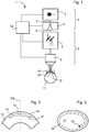
- Fig. 1 shows schematically a device 1 for carrying out a lenticle-extracting ametropia correction.
- the device 1 has a laser 2 which provides pulsed laser radiation, the laser 2 emitting a pulsed raw beam 3 in the described embodiment, which has a wavelength that penetrates the tissue of the cornea so that processing can take place there by means of non-linear effects .
- the raw beam 3 is shaped by a pulse shaper 4 with regard to the pulse duration, whereby a predistortion known from the prior art can take place, which ensures that after passing through the further optical path of the beam path in the material, ie in the cornea of the eye, the desired Pulse length of, for example, ⁇ 1 ps is present.
- the pulse shaper 4 and the laser 2 together form a laser beam source 5 which emits a pulsed laser beam 6 of the desired pulse length.
- the pulsed laser beam 6 falls further through a scanner 7, which preferably effects a two-dimensional deflection transversely to the direction of propagation of the laser radiation.
- the laser beam 6 scanned in this way is focused by an objective 8 into the cornea.
- the scanner 7, together with the objective 8, forms a beam shaping device 9 which ensures that the pulsed laser radiation 6 is focused at adjustable locations in a cornea of an eye, the focus diameter there being less than 3 ⁇ m.
- the laser beam source 5 can optionally include a so-called pulse picker, which can be part of the pulse shaper 4, for example.
- This pulse picker changes the raw beam 3 with regard to the frequency of the laser radiation pulses which have a processing effect in the cornea.
- the laser 2 it is possible to design the laser 2 in such a way that it provides a raw beam 3 with a pulse frequency that is significantly higher than the pulse frequency that is desired for the laser pulses of the laser beam 6 that are effective for processing.
- the pulse picker then reduces the frequency of the effective laser radiation pulses by rendering individual laser radiation pulses harmless with regard to their processing effect. This can be done, for example, by the pulse picker increasing the pulse length.
- the importance of the pulse picker, which is known in the prior art, will be explained later with reference to FIG Fig. 3 explained.
- the embodiment shown is the pulse frequency of the pulsed laser beam 6 between 1.2 MHz and 10 MHz, the frequency being based on those pulses that have a processing effect, ie pulses that have not been rendered harmless by a possibly present pulse picker.
- the energy of these pulses of the pulsed laser beam 6 is between 1 nJ and 200 nJ, preferably between 10 nJ and 100 nJ, particularly preferably between 20 nJ and 80 nJ.
- the wavelength of the laser beam 6 is in a range from 1030 nm to 1060 nm or from 300 nm to 400 nm or another spectral range that can penetrate the cornea, for which the cornea thus has a transmittance of at least 0.8.
- the device 1 further comprises a contact glass 10 which is used to fix the eye 11 and also to give a front surface of the cornea 12 of the eye 11 a desired and known shape.
- the corresponding contact surface of the contact glass 10 has a radius of curvature of 50 mm or smaller, particularly preferably 20 mm or smaller.
- the objective 8 bundles the laser radiation 6 into a focus 13, which lies within the cornea 12.
- the focus 13 has a maximum diameter of 3 ⁇ m, preferably a maximum of 2 ⁇ m.
- the maximum diameter is the largest diameter that z. B. in the case of an elliptical focus spot is measured along the major semi-axis. In the case of a circular spot, the spot diameter is the relevant dimension.
- Fig. 1 shows in dashed lines that, depending on the effect of the scanner 7, the focus 13 lies at different locations in the cornea 12 of the eye 11.
- the scanner 7 effects in the construction of Fig. 1 a deflection transversely to the main direction of incidence of the laser radiation 6.
- the focus position is adjusted along the main direction of incidence by suitable control of the objective 8, which is designed to be suitable for z-adjustment.
- the laser beam source 5 (in the design of Fig. 1 realized by laser 2 and pulse shaper 4) as well as the beam shaping device 9 (in the design of Fig. 1 implemented by scanner 7 and lens 8) are connected to a control unit 14 via control lines not designated further connected, which controls these elements appropriately.
- the control unit 14 generates a cut surface in the cornea of the eye through the activation.
- the corresponding relationships are shown in a sectional view in Fig. 2 which shows the cornea 12 schematically.
- a lenticle 15 is isolated in the cornea 12.
- the lenticle 15 is delimited anteriorly by a flap surface 16 and posteriorly by a lenticle surface 17.
- the flap surface 16 is at a constant distance from the front surface 18 of the cornea 12.
- the flap surface 16 is therefore not curved with respect to the front surface 18. This is different in the case of the lenticle surface 17, which is curved with respect to the front surface 18. Without such a curvature, the removal of the lenticle 15 would not change the curvature of the front surface 18 of the cornea 12.
- the lenticle surface 17, which is curved with respect to the front surface 18, on the other hand sets a change in the curvature of the front surface 18 of the cornea 12 when the lenticle 15 is removed. This removal is done by one in the Fig. 2 Lateral cut, not shown, which leads, for example, at the edge of the lenticle 15 from the flap surface 16 to the front surface 18 and allows the isolated lenticle 15 to be extracted, if necessary after the material of the lenticle 15 has been previously comminuted Fig. 2 flap surface 16 and lenticle surface 17 are symmetrical to the optical axis OA. This occurs automatically for the flap surface 16 when it is at a constant distance from the front surface 18.
- the boundary surfaces of the lenticle 15 can of course also comprise further surfaces.
- an additional edge surface can be provided which connects the flap surface 16 with the lenticle surface 17, which then has a more curved course than the flap surface 16 and the front surface 18.
- the cut surfaces for isolating the lenticule 15 are generated in that the focus 13 is shifted along a path which lies in the corresponding surface.
- Fig. 3 shown on the basis of the lenticle surface 17, which is elliptical here for reasons of clarity. This is intended to show that not only a spherical visual defect, but also an astigmatism can be corrected with the device 1.
- the lenticle 15 is no longer rotationally symmetrical to the optical axis OA.
- Fig. 3 shows a folding of the lenticule surface 17 in the plane of the drawing. Dashed is in Fig. 3 a track 19 entered. The position of the focus 13 is adjusted along this path.
- target points 20 are entered. They each designate a point to which a laser pulse of the pulsed laser radiation 6 is emitted.
- the lenticule surface 17 is formed as a cut surface.
- the distances between the target points 20 are selected in such a way that as far as possible no material bridges remain, that is, the lenticule surface 17 is generated over the entire surface as a cut surface.
- the pulse frequency of the pulsed laser beam 6 changeable. If you want to arrange the target points 20 as equidistant as possible, the pulse frequency and the displacement speed of the steel forming device 9 are to be adapted to one another. Since a laser 2 can usually only be adjusted with great effort at a high pulse frequency, it is advantageous to first provide a raw beam 3 with the laser 2, which has a pulse frequency that is greater than or equal to the maximum pulse frequency that is required for the laser beam 6 it is asked for. It can be easier to realize such a laser 2 and to combine it with a pulse picker than to build a laser whose pulse frequency is directly adjustable. In this way, the pulse frequency can be adapted to the displacement speed and the duration of the cutting surface generation is minimized.
Landscapes
- Health & Medical Sciences (AREA)
- Ophthalmology & Optometry (AREA)
- Heart & Thoracic Surgery (AREA)
- Vascular Medicine (AREA)
- Optics & Photonics (AREA)
- Surgery (AREA)
- Engineering & Computer Science (AREA)
- Biomedical Technology (AREA)
- Physics & Mathematics (AREA)
- Nuclear Medicine, Radiotherapy & Molecular Imaging (AREA)
- Life Sciences & Earth Sciences (AREA)
- Animal Behavior & Ethology (AREA)
- General Health & Medical Sciences (AREA)
- Public Health (AREA)
- Veterinary Medicine (AREA)
- Laser Surgery Devices (AREA)
Applications Claiming Priority (3)
| Application Number | Priority Date | Filing Date | Title |
|---|---|---|---|
| DE102013204496.8A DE102013204496A1 (de) | 2013-03-14 | 2013-03-14 | Erzeugung gekrümmter Schnitte im Inneren der Augenhornhaut |
| EP14703324.5A EP2967997B1 (fr) | 2013-03-14 | 2014-02-04 | Réalisation d'entailles courbées à l'intérieur de la cornée |
| PCT/EP2014/052167 WO2014139732A1 (fr) | 2013-03-14 | 2014-02-04 | Réalisation d'entailles courbées à l'intérieur de la cornée |
Related Parent Applications (1)
| Application Number | Title | Priority Date | Filing Date |
|---|---|---|---|
| EP14703324.5A Division EP2967997B1 (fr) | 2013-03-14 | 2014-02-04 | Réalisation d'entailles courbées à l'intérieur de la cornée |
Publications (1)
| Publication Number | Publication Date |
|---|---|
| EP3763342A1 true EP3763342A1 (fr) | 2021-01-13 |
Family
ID=50070537
Family Applications (2)
| Application Number | Title | Priority Date | Filing Date |
|---|---|---|---|
| EP20194913.8A Pending EP3763342A1 (fr) | 2013-03-14 | 2014-02-04 | Réalisation d'entailles courbées à l'intérieur de la cornée |
| EP14703324.5A Active EP2967997B1 (fr) | 2013-03-14 | 2014-02-04 | Réalisation d'entailles courbées à l'intérieur de la cornée |
Family Applications After (1)
| Application Number | Title | Priority Date | Filing Date |
|---|---|---|---|
| EP14703324.5A Active EP2967997B1 (fr) | 2013-03-14 | 2014-02-04 | Réalisation d'entailles courbées à l'intérieur de la cornée |
Country Status (4)
| Country | Link |
|---|---|
| US (3) | US10893979B2 (fr) |
| EP (2) | EP3763342A1 (fr) |
| DE (1) | DE102013204496A1 (fr) |
| WO (1) | WO2014139732A1 (fr) |
Families Citing this family (2)
| Publication number | Priority date | Publication date | Assignee | Title |
|---|---|---|---|---|
| DE102013204496A1 (de) * | 2013-03-14 | 2014-09-18 | Carl Zeiss Meditec Ag | Erzeugung gekrümmter Schnitte im Inneren der Augenhornhaut |
| CN112804974B (zh) * | 2018-09-20 | 2024-03-22 | 卡尔蔡司医疗技术股份公司 | 在眼睛内部中产生切口 |
Citations (13)
| Publication number | Priority date | Publication date | Assignee | Title |
|---|---|---|---|---|
| WO2003059563A2 (fr) | 2002-01-18 | 2003-07-24 | Carl Zeiss Meditec Ag | Systeme laser a femtosecondes pour le traitement precis de matiere et de tissus |
| US20040243112A1 (en) * | 2003-06-02 | 2004-12-02 | Mark Bendett | Apparatus and method for ophthalmologic surgical procedures using a femtosecond fiber laser |
| WO2004105661A1 (fr) | 2003-06-02 | 2004-12-09 | Carl Zeiss Meditec Ag | Procede et dispositif de traitement precis d'un materiau |
| WO2005011547A1 (fr) | 2003-07-25 | 2005-02-10 | Carl Zeiss Meditec Ag | Dispositif et procede pour former des surfaces de coupe courbes dans une matiere transparente |
| WO2008055698A1 (fr) | 2006-11-10 | 2008-05-15 | Carl Zeiss Meditec Ag | Dispositif de traitement de correction d'un défaut visuel de l'oeil par opération, procédé de production de données de commande pour ce dispositif et procédé de correction d'un défaut visuel de l'oeil par opération |
| WO2008055697A1 (fr) | 2006-11-10 | 2008-05-15 | Carl Zeiss Meditec Ag | Dispositif de traitement de correction d'un défaut visuel de l'oeil par opération, procédé de production de données de commande pour ce dispositif et procédé de correction d'un défaut visuel de l'oeil par opération |
| WO2008055705A1 (fr) | 2006-11-10 | 2008-05-15 | Carl Zeiss Meditec Ag | Dispositif de traitement de correction d'un défaut visuel de l'oeil par opération, procédé de production de données de commande pour ce dispositif et procédé de correction d'un défaut visuel par opération |
| WO2008055706A1 (fr) | 2006-11-10 | 2008-05-15 | Carl Zeiss Meditec Ag | Dispositif de planification destiné à préparer des données de commande pour un dispositif de traitement de correction d'un défaut visuel par opération, dispositif de traitement de correction d'un défaut visuel par opération et procédé de préparation de do |
| WO2008131878A1 (fr) | 2007-04-26 | 2008-11-06 | Carl Zeiss Meditec Ag | Post-traitement lors d'une correction de la réfraction par chirurgie de l'oeil |
| WO2009059711A1 (fr) | 2007-11-08 | 2009-05-14 | Carl Zeiss Meditec Ag | Dispositif de traitement permettant la correction chirurgicale de l'amétropie d'un oeil et procédé de génération de données de commande associées |
| WO2009059730A1 (fr) | 2007-11-08 | 2009-05-14 | Carl Zeiss Meditec Ag | Dispositif de traitement permettant la correction chirurgicale de l'amétropie d'un oeil, procédé de génération de données de commande associées et procédé de correction chirurgicale de l'amétropie d'un oeil |
| DE102008056488A1 (de) * | 2008-11-06 | 2010-05-12 | Carl Zeiss Meditec Ag | Ophthalmologisches Lasersystem und Betriebsverfahren |
| US20120078240A1 (en) * | 2010-09-25 | 2012-03-29 | Gregory John Roy Spooner | Laser apparatus and method for refractive surgery |
Family Cites Families (14)
| Publication number | Priority date | Publication date | Assignee | Title |
|---|---|---|---|---|
| US5984916A (en) | 1993-04-20 | 1999-11-16 | Lai; Shui T. | Ophthalmic surgical laser and method |
| US20080269731A1 (en) * | 2003-11-19 | 2008-10-30 | Casimir Andrew Swinger | Method and apparatus applying patient-verified prescription of high order aberrations |
| DE102004009212B4 (de) * | 2004-02-25 | 2015-08-20 | Carl Zeiss Meditec Ag | Kontaktelement für Laserbearbeitung und Laserbearbeitungsvorrichtung |
| ES2374819T3 (es) * | 2005-11-17 | 2012-02-22 | Wavelight Gmbh | Disposición para realizar tratamientos quirúrgicos con láser del ojo. |
| US8685006B2 (en) | 2006-11-10 | 2014-04-01 | Carl Zeiss Meditec Ag | Treatment apparatus for surgical correction of defective eyesight, method of generating control data therefore, and method for surgical correction of defective eyesight |
| US8623038B2 (en) | 2007-04-26 | 2014-01-07 | Carl Zeiss Meditec Ag | Re-treatment for ophthalmic correction of refraction |
| DE102007028042B3 (de) * | 2007-06-14 | 2008-08-07 | Universität Zu Lübeck | Verfahren zur Laserbearbeitung transparenter Materialien |
| US9545340B1 (en) * | 2007-06-26 | 2017-01-17 | University Of Rochester | Multi-photon absorption for femtosecond micromachining and refractive index modification of tissues |
| DE102008062658A1 (de) * | 2008-12-17 | 2010-06-24 | Carl Zeiss Meditec Ag | Ophthalmologisches Lasersystem und Betriebsverfahren |
| DE102011116759A1 (de) | 2011-10-20 | 2013-04-25 | Carl Zeiss Meditec Ag | Ophthalmologisches Lasersystem und Verfahren zum Durchtrennen von Augengewebe |
| DE102012007272B4 (de) * | 2012-04-12 | 2013-10-24 | Wavelight Gmbh | Lasereinrichtung und Verfahren zur Konfiguration einer solchen Lasereinrichtung |
| US20140052113A1 (en) | 2012-08-17 | 2014-02-20 | Carl Zeiss Meditec Ag | Instrument system and procedure for phacoemulsification |
| EP2705812A1 (fr) * | 2012-09-05 | 2014-03-12 | Universität zu Lübeck | Dispositif de découpage laser à l'intérieur d'un matériau transparent |
| DE102013204496A1 (de) * | 2013-03-14 | 2014-09-18 | Carl Zeiss Meditec Ag | Erzeugung gekrümmter Schnitte im Inneren der Augenhornhaut |
-
2013
- 2013-03-14 DE DE102013204496.8A patent/DE102013204496A1/de active Pending
-
2014
- 2014-02-04 EP EP20194913.8A patent/EP3763342A1/fr active Pending
- 2014-02-04 EP EP14703324.5A patent/EP2967997B1/fr active Active
- 2014-02-04 US US14/774,677 patent/US10893979B2/en active Active
- 2014-02-04 WO PCT/EP2014/052167 patent/WO2014139732A1/fr active Application Filing
-
2020
- 2020-09-29 US US17/037,441 patent/US11602458B2/en active Active
-
2023
- 2023-02-27 US US18/175,367 patent/US20230277378A1/en active Pending
Patent Citations (15)
| Publication number | Priority date | Publication date | Assignee | Title |
|---|---|---|---|---|
| WO2003059563A2 (fr) | 2002-01-18 | 2003-07-24 | Carl Zeiss Meditec Ag | Systeme laser a femtosecondes pour le traitement precis de matiere et de tissus |
| US20040243112A1 (en) * | 2003-06-02 | 2004-12-02 | Mark Bendett | Apparatus and method for ophthalmologic surgical procedures using a femtosecond fiber laser |
| WO2004105661A1 (fr) | 2003-06-02 | 2004-12-09 | Carl Zeiss Meditec Ag | Procede et dispositif de traitement precis d'un materiau |
| WO2004105660A1 (fr) | 2003-06-02 | 2004-12-09 | Carl Zeiss Meditec Ag | Appareil et procede permettant de realiser des interventions chirurgicales ophtalmologiques a l'aide d'un laser femtoseconde a fibres |
| EP1628606B1 (fr) | 2003-06-02 | 2011-07-13 | Carl Zeiss Meditec AG | Dispositif de traitement precis d'un materiau |
| WO2005011547A1 (fr) | 2003-07-25 | 2005-02-10 | Carl Zeiss Meditec Ag | Dispositif et procede pour former des surfaces de coupe courbes dans une matiere transparente |
| WO2008055697A1 (fr) | 2006-11-10 | 2008-05-15 | Carl Zeiss Meditec Ag | Dispositif de traitement de correction d'un défaut visuel de l'oeil par opération, procédé de production de données de commande pour ce dispositif et procédé de correction d'un défaut visuel de l'oeil par opération |
| WO2008055705A1 (fr) | 2006-11-10 | 2008-05-15 | Carl Zeiss Meditec Ag | Dispositif de traitement de correction d'un défaut visuel de l'oeil par opération, procédé de production de données de commande pour ce dispositif et procédé de correction d'un défaut visuel par opération |
| WO2008055706A1 (fr) | 2006-11-10 | 2008-05-15 | Carl Zeiss Meditec Ag | Dispositif de planification destiné à préparer des données de commande pour un dispositif de traitement de correction d'un défaut visuel par opération, dispositif de traitement de correction d'un défaut visuel par opération et procédé de préparation de do |
| WO2008055698A1 (fr) | 2006-11-10 | 2008-05-15 | Carl Zeiss Meditec Ag | Dispositif de traitement de correction d'un défaut visuel de l'oeil par opération, procédé de production de données de commande pour ce dispositif et procédé de correction d'un défaut visuel de l'oeil par opération |
| WO2008131878A1 (fr) | 2007-04-26 | 2008-11-06 | Carl Zeiss Meditec Ag | Post-traitement lors d'une correction de la réfraction par chirurgie de l'oeil |
| WO2009059711A1 (fr) | 2007-11-08 | 2009-05-14 | Carl Zeiss Meditec Ag | Dispositif de traitement permettant la correction chirurgicale de l'amétropie d'un oeil et procédé de génération de données de commande associées |
| WO2009059730A1 (fr) | 2007-11-08 | 2009-05-14 | Carl Zeiss Meditec Ag | Dispositif de traitement permettant la correction chirurgicale de l'amétropie d'un oeil, procédé de génération de données de commande associées et procédé de correction chirurgicale de l'amétropie d'un oeil |
| DE102008056488A1 (de) * | 2008-11-06 | 2010-05-12 | Carl Zeiss Meditec Ag | Ophthalmologisches Lasersystem und Betriebsverfahren |
| US20120078240A1 (en) * | 2010-09-25 | 2012-03-29 | Gregory John Roy Spooner | Laser apparatus and method for refractive surgery |
Non-Patent Citations (1)
| Title |
|---|
| KARSTEN KOENIG ET AL: "Intratissue surgery with 80 MHz nanojoule femtosecond laser pulses in the near infrared", OPTICS EXPRESS, vol. 10, no. 3, 11 February 2002 (2002-02-11), pages 171 - 176, XP055108893, ISSN: 1094-4087, DOI: 10.1364/OE.10.000171 * |
Also Published As
| Publication number | Publication date |
|---|---|
| US11602458B2 (en) | 2023-03-14 |
| EP2967997A1 (fr) | 2016-01-20 |
| WO2014139732A1 (fr) | 2014-09-18 |
| DE102013204496A1 (de) | 2014-09-18 |
| EP2967997B1 (fr) | 2020-09-09 |
| US10893979B2 (en) | 2021-01-19 |
| US20230277378A1 (en) | 2023-09-07 |
| US20210007892A1 (en) | 2021-01-14 |
| US20160022494A1 (en) | 2016-01-28 |
Similar Documents
| Publication | Publication Date | Title |
|---|---|---|
| EP3225221B1 (fr) | Dispositif et procédé de traitement de matériau à l'aide d'un rayon laser | |
| EP2521519B1 (fr) | Système laser ophtalmologique | |
| DE102012018421A1 (de) | Augenchirurgische Refraktionskorrektur | |
| DE102008017293A1 (de) | Verfahren zum Erzeugen von Steuerdaten für die Augenchirurgie sowie augenchirurgische Behandlungsvorrichtung und -verfahren | |
| DE102013218415A1 (de) | Augenchirurgisches Verfahren | |
| DE102012022080A1 (de) | Augenchirurgisches Verfahren | |
| DE102012022079A1 (de) | Augenchirurgisches Verfahren | |
| EP3454802B1 (fr) | Dispositif de planification et procede de generation de donnees de commande pour un dispositif de chirurgie ophtalmique | |
| DE102015002729A1 (de) | Ophthalmologische Lasertherapievorrichtung und Verfahren zur Erzeugung cornealer Zugangsschnitte | |
| DE102016218564A1 (de) | Augenchirurgisches Verfahren | |
| DE102016208012A1 (de) | Augenchirurgisches Verfahren | |
| DE102017207529A1 (de) | Nachbehandlung bei augenchirurgischer Refraktionskorrektur | |
| EP2648667B1 (fr) | Dispositif pour le traitement par incision de la cornée d'un oeil humain par faisceau laser pulsé focalisé | |
| DE102011108645A1 (de) | "Nachbehandlung bei augenchirurgischer Refraktionskorrektur" | |
| DE102013004688A1 (de) | Augenchirurgisches Verfahren | |
| EP2136749A2 (fr) | Dispositif et procédé pour le traitement de matière au moyen d'un rayonnement laser | |
| EP2967997B1 (fr) | Réalisation d'entailles courbées à l'intérieur de la cornée | |
| WO2016050711A1 (fr) | Procédé de chirurgie oculaire | |
| DE102015218909A1 (de) | Augenchirurgisches Verfahren | |
| DE102012014769A1 (de) | Fortsetzung von unterbrochenen augenchirurgischen Schnitten | |
| WO2016050779A1 (fr) | Production de coupes dans un matériau transparent à l'aide d'un rayonnement optique | |
| DE102019213869A1 (de) | Erzeugung von Schnitten im Inneren des Auges | |
| DE102013219788A1 (de) | Intra-Cornealer Ring | |
| DE102012022081A1 (de) | Nachbehandlung bei augenchirurgischer Refrationskorrektur | |
| DE102019134146B4 (de) | Verfahren zur Steuerung eines augenchirurgischen Lasers und Behandlungsvorrichtung |
Legal Events
| Date | Code | Title | Description |
|---|---|---|---|
| PUAI | Public reference made under article 153(3) epc to a published international application that has entered the european phase |
Free format text: ORIGINAL CODE: 0009012 |
|
| STAA | Information on the status of an ep patent application or granted ep patent |
Free format text: STATUS: THE APPLICATION HAS BEEN PUBLISHED |
|
| AC | Divisional application: reference to earlier application |
Ref document number: 2967997 Country of ref document: EP Kind code of ref document: P |
|
| AK | Designated contracting states |
Kind code of ref document: A1 Designated state(s): AL AT BE BG CH CY CZ DE DK EE ES FI FR GB GR HR HU IE IS IT LI LT LU LV MC MK MT NL NO PL PT RO RS SE SI SK SM TR |
|
| STAA | Information on the status of an ep patent application or granted ep patent |
Free format text: STATUS: REQUEST FOR EXAMINATION WAS MADE |
|
| 17P | Request for examination filed |
Effective date: 20210706 |
|
| RBV | Designated contracting states (corrected) |
Designated state(s): AL AT BE BG CH CY CZ DE DK EE ES FI FR GB GR HR HU IE IS IT LI LT LU LV MC MK MT NL NO PL PT RO RS SE SI SK SM TR |
|
| STAA | Information on the status of an ep patent application or granted ep patent |
Free format text: STATUS: EXAMINATION IS IN PROGRESS |
|
| 17Q | First examination report despatched |
Effective date: 20231215 |