EP3763301B1 - Conception glénoïdienne augmentée - Google Patents
Conception glénoïdienne augmentée Download PDFInfo
- Publication number
- EP3763301B1 EP3763301B1 EP20185044.3A EP20185044A EP3763301B1 EP 3763301 B1 EP3763301 B1 EP 3763301B1 EP 20185044 A EP20185044 A EP 20185044A EP 3763301 B1 EP3763301 B1 EP 3763301B1
- Authority
- EP
- European Patent Office
- Prior art keywords
- implant
- contacting surface
- bone contacting
- glenoid
- anchor
- Prior art date
- Legal status (The legal status is an assumption and is not a legal conclusion. Google has not performed a legal analysis and makes no representation as to the accuracy of the status listed.)
- Active
Links
- 241001653121 Glenoides Species 0.000 title claims description 94
- 230000003190 augmentative effect Effects 0.000 title description 24
- 239000007943 implant Substances 0.000 claims description 131
- 210000000988 bone and bone Anatomy 0.000 claims description 99
- 229910052751 metal Inorganic materials 0.000 claims description 23
- 239000002184 metal Substances 0.000 claims description 23
- 230000007704 transition Effects 0.000 claims description 11
- 229920000642 polymer Polymers 0.000 claims description 9
- 230000008878 coupling Effects 0.000 description 17
- 238000010168 coupling process Methods 0.000 description 17
- 238000005859 coupling reaction Methods 0.000 description 17
- RTAQQCXQSZGOHL-UHFFFAOYSA-N Titanium Chemical compound [Ti] RTAQQCXQSZGOHL-UHFFFAOYSA-N 0.000 description 11
- 239000010936 titanium Substances 0.000 description 11
- 229910052719 titanium Inorganic materials 0.000 description 11
- 230000015556 catabolic process Effects 0.000 description 10
- 238000006731 degradation reaction Methods 0.000 description 10
- 210000004095 humeral head Anatomy 0.000 description 10
- 230000001054 cortical effect Effects 0.000 description 9
- 241000284156 Clerodendrum quadriloculare Species 0.000 description 7
- 230000003628 erosive effect Effects 0.000 description 7
- 230000002093 peripheral effect Effects 0.000 description 7
- 230000000295 complement effect Effects 0.000 description 6
- 238000006243 chemical reaction Methods 0.000 description 5
- 230000007246 mechanism Effects 0.000 description 5
- 238000000034 method Methods 0.000 description 5
- 238000011882 arthroplasty Methods 0.000 description 3
- 229920000249 biocompatible polymer Polymers 0.000 description 3
- 230000006835 compression Effects 0.000 description 3
- 238000007906 compression Methods 0.000 description 3
- 238000002513 implantation Methods 0.000 description 3
- 238000002360 preparation method Methods 0.000 description 3
- 210000000323 shoulder joint Anatomy 0.000 description 3
- 239000000654 additive Substances 0.000 description 2
- 230000000996 additive effect Effects 0.000 description 2
- 238000004873 anchoring Methods 0.000 description 2
- 230000037182 bone density Effects 0.000 description 2
- 230000037118 bone strength Effects 0.000 description 2
- 230000001419 dependent effect Effects 0.000 description 2
- 238000010586 diagram Methods 0.000 description 2
- 238000004519 manufacturing process Methods 0.000 description 2
- 238000000465 moulding Methods 0.000 description 2
- 230000007935 neutral effect Effects 0.000 description 2
- 230000008569 process Effects 0.000 description 2
- 210000004872 soft tissue Anatomy 0.000 description 2
- 239000007787 solid Substances 0.000 description 2
- 230000008859 change Effects 0.000 description 1
- 239000002131 composite material Substances 0.000 description 1
- 238000002591 computed tomography Methods 0.000 description 1
- 238000005520 cutting process Methods 0.000 description 1
- 238000001746 injection moulding Methods 0.000 description 1
- 239000007788 liquid Substances 0.000 description 1
- 238000002595 magnetic resonance imaging Methods 0.000 description 1
- 239000000463 material Substances 0.000 description 1
- 150000002739 metals Chemical class 0.000 description 1
- 210000003205 muscle Anatomy 0.000 description 1
- 239000002861 polymer material Substances 0.000 description 1
- 230000002265 prevention Effects 0.000 description 1
- 238000002271 resection Methods 0.000 description 1
- 235000012773 waffles Nutrition 0.000 description 1
Images


Classifications
-
- A—HUMAN NECESSITIES
- A61—MEDICAL OR VETERINARY SCIENCE; HYGIENE
- A61F—FILTERS IMPLANTABLE INTO BLOOD VESSELS; PROSTHESES; DEVICES PROVIDING PATENCY TO, OR PREVENTING COLLAPSING OF, TUBULAR STRUCTURES OF THE BODY, e.g. STENTS; ORTHOPAEDIC, NURSING OR CONTRACEPTIVE DEVICES; FOMENTATION; TREATMENT OR PROTECTION OF EYES OR EARS; BANDAGES, DRESSINGS OR ABSORBENT PADS; FIRST-AID KITS
- A61F2/00—Filters implantable into blood vessels; Prostheses, i.e. artificial substitutes or replacements for parts of the body; Appliances for connecting them with the body; Devices providing patency to, or preventing collapsing of, tubular structures of the body, e.g. stents
- A61F2/02—Prostheses implantable into the body
- A61F2/30—Joints
- A61F2/40—Joints for shoulders
- A61F2/4081—Glenoid components, e.g. cups
-
- A—HUMAN NECESSITIES
- A61—MEDICAL OR VETERINARY SCIENCE; HYGIENE
- A61F—FILTERS IMPLANTABLE INTO BLOOD VESSELS; PROSTHESES; DEVICES PROVIDING PATENCY TO, OR PREVENTING COLLAPSING OF, TUBULAR STRUCTURES OF THE BODY, e.g. STENTS; ORTHOPAEDIC, NURSING OR CONTRACEPTIVE DEVICES; FOMENTATION; TREATMENT OR PROTECTION OF EYES OR EARS; BANDAGES, DRESSINGS OR ABSORBENT PADS; FIRST-AID KITS
- A61F2/00—Filters implantable into blood vessels; Prostheses, i.e. artificial substitutes or replacements for parts of the body; Appliances for connecting them with the body; Devices providing patency to, or preventing collapsing of, tubular structures of the body, e.g. stents
- A61F2/02—Prostheses implantable into the body
- A61F2/30—Joints
- A61F2/30721—Accessories
- A61F2/30734—Modular inserts, sleeves or augments, e.g. placed on proximal part of stem for fixation purposes or wedges for bridging a bone defect
-
- A—HUMAN NECESSITIES
- A61—MEDICAL OR VETERINARY SCIENCE; HYGIENE
- A61F—FILTERS IMPLANTABLE INTO BLOOD VESSELS; PROSTHESES; DEVICES PROVIDING PATENCY TO, OR PREVENTING COLLAPSING OF, TUBULAR STRUCTURES OF THE BODY, e.g. STENTS; ORTHOPAEDIC, NURSING OR CONTRACEPTIVE DEVICES; FOMENTATION; TREATMENT OR PROTECTION OF EYES OR EARS; BANDAGES, DRESSINGS OR ABSORBENT PADS; FIRST-AID KITS
- A61F2/00—Filters implantable into blood vessels; Prostheses, i.e. artificial substitutes or replacements for parts of the body; Appliances for connecting them with the body; Devices providing patency to, or preventing collapsing of, tubular structures of the body, e.g. stents
- A61F2/02—Prostheses implantable into the body
- A61F2/30—Joints
- A61F2/30767—Special external or bone-contacting surface, e.g. coating for improving bone ingrowth
- A61F2/30771—Special external or bone-contacting surface, e.g. coating for improving bone ingrowth applied in original prostheses, e.g. holes or grooves
-
- A—HUMAN NECESSITIES
- A61—MEDICAL OR VETERINARY SCIENCE; HYGIENE
- A61F—FILTERS IMPLANTABLE INTO BLOOD VESSELS; PROSTHESES; DEVICES PROVIDING PATENCY TO, OR PREVENTING COLLAPSING OF, TUBULAR STRUCTURES OF THE BODY, e.g. STENTS; ORTHOPAEDIC, NURSING OR CONTRACEPTIVE DEVICES; FOMENTATION; TREATMENT OR PROTECTION OF EYES OR EARS; BANDAGES, DRESSINGS OR ABSORBENT PADS; FIRST-AID KITS
- A61F2/00—Filters implantable into blood vessels; Prostheses, i.e. artificial substitutes or replacements for parts of the body; Appliances for connecting them with the body; Devices providing patency to, or preventing collapsing of, tubular structures of the body, e.g. stents
- A61F2/02—Prostheses implantable into the body
- A61F2/30—Joints
- A61F2/30721—Accessories
- A61F2/30734—Modular inserts, sleeves or augments, e.g. placed on proximal part of stem for fixation purposes or wedges for bridging a bone defect
- A61F2002/30736—Augments or augmentation pieces, e.g. wedges or blocks for bridging a bone defect
-
- A—HUMAN NECESSITIES
- A61—MEDICAL OR VETERINARY SCIENCE; HYGIENE
- A61F—FILTERS IMPLANTABLE INTO BLOOD VESSELS; PROSTHESES; DEVICES PROVIDING PATENCY TO, OR PREVENTING COLLAPSING OF, TUBULAR STRUCTURES OF THE BODY, e.g. STENTS; ORTHOPAEDIC, NURSING OR CONTRACEPTIVE DEVICES; FOMENTATION; TREATMENT OR PROTECTION OF EYES OR EARS; BANDAGES, DRESSINGS OR ABSORBENT PADS; FIRST-AID KITS
- A61F2/00—Filters implantable into blood vessels; Prostheses, i.e. artificial substitutes or replacements for parts of the body; Appliances for connecting them with the body; Devices providing patency to, or preventing collapsing of, tubular structures of the body, e.g. stents
- A61F2/02—Prostheses implantable into the body
- A61F2/30—Joints
- A61F2/30767—Special external or bone-contacting surface, e.g. coating for improving bone ingrowth
- A61F2/30771—Special external or bone-contacting surface, e.g. coating for improving bone ingrowth applied in original prostheses, e.g. holes or grooves
- A61F2002/30841—Sharp anchoring protrusions for impaction into the bone, e.g. sharp pins, spikes
- A61F2002/30843—Pyramidally-shaped
-
- A—HUMAN NECESSITIES
- A61—MEDICAL OR VETERINARY SCIENCE; HYGIENE
- A61F—FILTERS IMPLANTABLE INTO BLOOD VESSELS; PROSTHESES; DEVICES PROVIDING PATENCY TO, OR PREVENTING COLLAPSING OF, TUBULAR STRUCTURES OF THE BODY, e.g. STENTS; ORTHOPAEDIC, NURSING OR CONTRACEPTIVE DEVICES; FOMENTATION; TREATMENT OR PROTECTION OF EYES OR EARS; BANDAGES, DRESSINGS OR ABSORBENT PADS; FIRST-AID KITS
- A61F2/00—Filters implantable into blood vessels; Prostheses, i.e. artificial substitutes or replacements for parts of the body; Appliances for connecting them with the body; Devices providing patency to, or preventing collapsing of, tubular structures of the body, e.g. stents
- A61F2/02—Prostheses implantable into the body
- A61F2/30—Joints
- A61F2/30767—Special external or bone-contacting surface, e.g. coating for improving bone ingrowth
- A61F2/30771—Special external or bone-contacting surface, e.g. coating for improving bone ingrowth applied in original prostheses, e.g. holes or grooves
- A61F2002/30878—Special external or bone-contacting surface, e.g. coating for improving bone ingrowth applied in original prostheses, e.g. holes or grooves with non-sharp protrusions, for instance contacting the bone for anchoring, e.g. keels, pegs, pins, posts, shanks, stems, struts
- A61F2002/30891—Plurality of protrusions
- A61F2002/30892—Plurality of protrusions parallel
-
- A—HUMAN NECESSITIES
- A61—MEDICAL OR VETERINARY SCIENCE; HYGIENE
- A61F—FILTERS IMPLANTABLE INTO BLOOD VESSELS; PROSTHESES; DEVICES PROVIDING PATENCY TO, OR PREVENTING COLLAPSING OF, TUBULAR STRUCTURES OF THE BODY, e.g. STENTS; ORTHOPAEDIC, NURSING OR CONTRACEPTIVE DEVICES; FOMENTATION; TREATMENT OR PROTECTION OF EYES OR EARS; BANDAGES, DRESSINGS OR ABSORBENT PADS; FIRST-AID KITS
- A61F2/00—Filters implantable into blood vessels; Prostheses, i.e. artificial substitutes or replacements for parts of the body; Appliances for connecting them with the body; Devices providing patency to, or preventing collapsing of, tubular structures of the body, e.g. stents
- A61F2/02—Prostheses implantable into the body
- A61F2/30—Joints
- A61F2/30767—Special external or bone-contacting surface, e.g. coating for improving bone ingrowth
- A61F2002/3092—Special external or bone-contacting surface, e.g. coating for improving bone ingrowth having an open-celled or open-pored structure
-
- A—HUMAN NECESSITIES
- A61—MEDICAL OR VETERINARY SCIENCE; HYGIENE
- A61F—FILTERS IMPLANTABLE INTO BLOOD VESSELS; PROSTHESES; DEVICES PROVIDING PATENCY TO, OR PREVENTING COLLAPSING OF, TUBULAR STRUCTURES OF THE BODY, e.g. STENTS; ORTHOPAEDIC, NURSING OR CONTRACEPTIVE DEVICES; FOMENTATION; TREATMENT OR PROTECTION OF EYES OR EARS; BANDAGES, DRESSINGS OR ABSORBENT PADS; FIRST-AID KITS
- A61F2/00—Filters implantable into blood vessels; Prostheses, i.e. artificial substitutes or replacements for parts of the body; Appliances for connecting them with the body; Devices providing patency to, or preventing collapsing of, tubular structures of the body, e.g. stents
- A61F2/02—Prostheses implantable into the body
- A61F2/30—Joints
- A61F2/40—Joints for shoulders
- A61F2/4081—Glenoid components, e.g. cups
- A61F2002/4085—Glenoid components, e.g. cups having a convex shape, e.g. hemispherical heads
Definitions
- Eccentric glenoid erosion occurs in as much as 40% of shoulder arthroplasty candidates. Wear can present anteriorly, superiorly and posteriorly, with superior being most common in reverse shoulder arthroplasty (“RSA”) candidates, and posterior being most prevalent in total shoulder arthroplasty (“TSA”) candidates. As the articular surface of the glenoid wears or degrades over time, the glenoid surface may take a biconcave shape. The worn or degraded portion of the glenoid may be referred to as the neoglenoid and the original portion of the glenoid may be referred to as the paleoglenoid.
- a glenoid implant is given in US 2014/0257495 .
- Any glenoid implant that does not have a biconvex design to match the concave surface of a glenoid with eccentric glenoid erosion may require removal of a relatively large amount of bone stock, including portions of the paleoglenoid, which may be undesirable.
- the relative sizes and shapes of the paleoglenoid and the neoglenoid may also change. It would thus be preferably to have an augmented glenoid implant that is capable of being implanted onto a glenoid with eccentric glenoid erosion to minimize the amount of native bone stock that needs to be removed.
- an augmented glenoid implant or implant system that performs well when implanted onto a native glenoid with eccentric glenoid erosion. It would additionally be preferable to have an augmented glenoid implant or implant system that is suitable for use in patients with different progressions of eccentric glenoid erosion.
- a glenoid implant as defined in claim 1 and the corresponding dependent claims.
- a glenoid implant may include an articulating surface, a bone contacting surface opposite the articulating surface, at least one first anchor, and at least one second anchor.
- the bone contacting surface may include a first portion with a first convexity configured to contact an anterior portion of the glenoid and a second portion with a second convexity configured to contact a posterior portion of the glenoid, the first convexity being different than the second convexity.
- the at least one first anchor may extend from the first portion of the bone contacting surface and may include a first substantially planar surface.
- the at least one second anchor may extend from the second portion of the bone contacting surface and may include a second substantially planar surface.
- the first and second substantially planar surfaces may be parallel to each other and may be substantially orthogonal to a third axis extending in a later-anterior to medial-posterior direction.
- a glenoid implant may include an articulating surface, a bone contacting surface opposite the articulating surface, a first plurality of anchors, and a second plurality of anchors.
- the bone contacting surface may include a first portion with a first convexity configured to contact a first portion of the glenoid and a second portion with a second convexity configured to contact a second portion of the glenoid, the first convexity being different than the second convexity.
- the first plurality of anchors may extend from the first portion of the bone contacting surface along a first axis.
- the second plurality of anchors may extend form the second portion of the bone contacting surface along a second axis.
- the first and second axis may be transverse to a third axis.
- the third axis may extend in a lateral-anterior to medial-posterior direction.
- a glenoid implant may include a bearing component defining an articulating surface and an augment component.
- the bearing component may be comprised of a polymer.
- the augment component may be comprised of metal.
- the augment component may form at least a portion of a bone contacting surface. At least one projection may extend from the bone contacting surface.
- proximal means situated nearer to the heart of the body and the term “distal” means more situated away from the heart.
- anterior means towards the front part of the body or the face and the term “posterior” means towards the back of the body.
- medial means toward the midline of the body and the term “lateral” means away from the midline of the body.
- about means toward the midline of the body and the term “lateral” means away from the midline of the body.
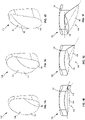
- FIGS. 1A-1F depict a right glenoid implant.
- a left glenoid implant may be provided that is substantially identical to the right glenoid implants described herein, although the left glenoid implants may be a substantially mirror image to the right glenoid implants described.
- FIGS. 1A, 1C, 1E depict side perspective views, while FIGS. 1B , ID, IF depict corresponding perspective views.
- the glenoid implant 100 has an articulating surface 102 and a bone contacting surface 104.
- the articulating surface 102 is intended for articulating with a corresponding humeral head of the shoulder joint, whether a native or prosthetic humeral head.
- the bone contacting surface 104 is intended for being in contact with the patient's glenoid upon implantation.
- a first portion 106 of the implant 100 is located on a generally anterior portion of implant 100.
- the first portion 106 has a first convexity sized and shaped to match or substantially match the concavity of the paleoglenoid.
- a second portion 108 of the implant 100 is located on a generally posterior portion of implant 100.
- the second portion 108 has a second convexity sized and shaped to match or substantially match the concavity of the neoglenoid.
- the convexity of the first portion 106 is different from the convexity of the second portion 108.
- the different convexities of the first portion 106 and the second portion 108 results in the bone contacting surface 104 having a biconvex shape.
- the biconvex shape is configured to better match the degradation of the glenoid in the case of eccentric glenoid degradation that produces a neoglenoid in addition to the paleoglenoid. In such circumstances, the glenoid does not degrade evenly, thereby forming the neoglenoid and the paleoglenoid as noted above.
- the neoglenoid is the portion that is worn or degraded such that it becomes a secondary-articular surface formed of cortical-type bone. The portion of the glenoid that is not (or is less significantly) degraded or worn is the paleoglenoid.
- the biconvexity of the implant 100 allows the implant to have better contact with the eccentrically-worn glenoid upon implantation.
- the first portion 106 and the second portion 108 meet or intersect at different locations on implant 100 depending on the degree or severity of degradation found in the native glenoid being replaced.
- the glenoid implant 100 of FIGS. 1A-B has a relatively small neoglenoid component (or second portion) 108 and a relatively large paleoglenoid component (or first portion) 106 compared to the other embodiments.
- the glenoid implant 100 of FIGS. 1E-F has a relatively large neoglenoid component (or second portion) 108 and a relatively small paleoglenoid component (or first portion) 106 compared to the other embodiments.
- FIGS. 1C-D has a neoglenoid component (or second portion) 108 and a paleoglenoid component (or first portion) 106 with a size generally inbetween the other two embodiments.
- the differences in the size and position of the neoglenoid component (or second portion) 108 may generally correspond to an increasing progression in eccentric glenoid degradation, with FIGS. 1A-B corresponding to a relatively early progression of eccentric degradation and FIGS. 1E-F corresponding to a relatively late progression of eccentric degradation.
- the first portion 106 and the second portion 108 meet at an angle transverse from the anterior-posterior axis of the implant 100. In the view of FIGS.
- the anterior direction generally corresponds to the left side of the page, while the posterior direction generally corresponds to the right side of the page.
- the angle may be about 30 degrees from the anterior-posterior axis such that the first portion 106 and the second portions 108 intersect at a 30 degree posterior bias of the neoglenoid.
- the angle may be about 10 degrees below the anterior-posterior axis.
- angles are merely exemplary, and unless noted otherwise, other angles, including angles of between about 10 degrees and about 30 degrees may be appropriate. While it is described that the first portion 106 and second potion 108 meet at an angle, that angle is descriptive of the direction of the line of intersection.
- the line of intersection between the first portion 106 and the second portions 108 may be a curved line that follows a typical progression of degradation, which starts posterior to the midline and moves anterior of the midline as the glenoid wears away.
- FIGS. 1A and 1B depict implant 100 for instances in which there is a relatively small amount of degradation of the glenoid whereas FIGS. IE, IF depict implant 100 for instances in which there is a relatively large amount of degradation of the glenoid.
- the bone contacting surface 104 of the second portion 108 may be inclined with respect to the bone contacting surface 104 of the first portion 106. Therefore, the apex of the second portion 108 may extend past the apex of the convex bone contacting surface 104 of the first potion 106.
- the angle of inclination ⁇ may be about 15 degrees. However, it should be understood that such an angle is merely exemplary, and unless noted otherwise, other angles, including angles of between about 5 degrees and about 30 degrees may be appropriate.
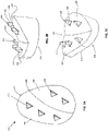
- FIGS. 2A and 2B depict a glenoid implant 200 having a bone contacting surface 204 and an articular surface 202.
- the overall shape of glenoid implant 200 is generally similar to that of glenoid implant 100 shown in FIGS. 1B-C , with the primary exception that additional fixation features are provided on the bone contacting surface 204.
- the bone contacting surface 204 has a biconvex shape such that there is a first portion 206 with a first convexity configured to contact an anterior or paleoglenoid portion of the native glenoid and a second portion 208 with a second convexity configured to contact a posterior or neoglenoid portion of the native glenoid.
- implant 200 may have different configurations in which the first portion 206 and the second portion 208 vary in size, similar to the variations shown in FIGS. 1A-1F .
- Implant 200 includes a plurality of first anchors 210 and a plurality of second anchors 220 extending medially, away from the bone contacting surface 204. At least one first anchor 210 extends from the first potion 206 and at least one second anchor 220 extends from the second portion 208. For purposes of clarity, only one anchor on each the first and second portion 206, 208 is labeled in FIGS. 2A-C .
- areas of bone corresponding to the anchor's size, shape, and location may be resected.
- complementary recesses may be cut into the glenoid. The complementary recesses may be cut such that they are slightly undersized as compared to the size of the anchors 210, 220.
- the glenoid may require preparation prior to the implantation of implant 200.
- a surgical robot with an associated cutting tool and/or an associated computer may be programmed to form a concave curvature in the glenoid corresponding to the biconvexity of implant 200.
- a robot may be used to precisely resect the glenoid to create recesses that are complementary to the anchors 210, 220 of implant 200.
- Use of a robot may provide for greater precision, compared to manual preparation of the bone, in the size, shape, and location of the resected bone as the robot can be programmed to perform the resection based on data provided by scans of the patient.
- the patient's glenoid may be imaged via any suitable modality, such as MRI or CT scanning, and the data acquired from the scanning may be manipulated to create a surgical plan to precisely resect the patient's glenoid to have the desired shape to receive the implant 200.
- the shape and/or geometry of the particular implant 200 may also be uploaded to the surgical system to assist in the planning.
- the surgical plan may be fed to a robotic surgical system and may be implemented by the robotic surgical system, with or without assistance by a surgeon.
- anchors 210, 220 have a wedge like shape.
- First anchor 210 has a substantially planar surface 212 and second anchor 220 has a substantially planar surface 222.
- Substantially planar surfaces 212, 222 may be parallel or substantially parallel to one another and extend away from the bone contacting surface traverse to an axis in a lateral-anterior to medial-posterior direction.
- the axis that lies in the lateral-anterior to medial-posterior direction can be considered a "slip plane," described in greater detail below.
- FIGS. 3A-C depict force diagrams on a representative right glenoid.
- the portion of the bone shown in FIGS. 3A-C is a view of the right shoulder in a superior to inferior direction (i.e. looking down from above the shoulder).
- a representative humeral head of the shoulder joint is shown in FIGS. 3A-C as a circular member that interacts with, and applies forces to, the glenoid of the shoulder j oint.
- the anterior direction is shown in FIG. 3A .
- the joint reaction force is exerted on the glenoid in the medial direction in a normal, neutral state, with the glenoid and associated soft tissue, such as the infraspinatus and subscapularis muscles, helping to maintain the humeral head in contact with the glenoid.
- FIG. 3B illustrates the humeral head in an anterior position relative to the glenoid, which may be a typical position during typical use of the shoulder.
- compression force is applied to the glenoid in the medial direction and a shear force is applied to the glenoid in the posterior direction, for example as a result of soft tissue tending to push the humeral head to the neutral position shown in FIG. 3A . Therefore, the resultant force (i.e. the combination of the compression force and the shear force) in the edge-loaded state is the joint reaction force exerted on the bone at an angle in the posterior-medial direction.
- FIG. 3C illustrates a humeral head in an edge-loaded state, similar to FIG. 3B , with the exception that the glenoid shown in FIG. 3C has eccentric erosion with an augmented glenoid implant, similar to implant 100 and/or implant 200, implanted thereon.
- the posterior-medial directed force exerted on the augmented glenoid by the edge-loaded humeral head tends to cause the augmented glenoid implant to want to slip or move along the slip plane illustrated in FIG. 3C , which may be generally aligned with the surface of the neoglenoid.
- the resultant joint reaction force may create a potential for implant 200 to slip along the bone, thereby creating a "slip plane.”
- the slip plane effectively bisects the line of intersection of the neoglenoid and paleoglenoid and lies in a plane tangential to the bone contacting surface of the neoglenoid portion of the implant.
- substantially planar surfaces 212, 222 are substantially orthogonal to the axis of the slip plane to assist in the prevention of implant 200 from slipping.
- substantially planar surfaces 212, 222 will exert a force on the area of resected bone within which the anchors 210, 220 are implanted.
- the substantially planar shape of surfaces 212, 222 creates a relatively large amount of surface area of contact with the glenoid, which further assists in preventing slipping along the slip plane.
- the force exerted by the substantially planar surfaces 212, 222 and the reaction force experienced by the anchors 210, 220 will thus tend to prevent the implant 200 from slipping along the slip plane.
- the shape of the anchors 210, 220 allow for size of the anchors to be minimized without compromising function. As should be understood, there is generally a desire to maintain the most amount of healthy bone stock when implanting a prosthesis onto the bone, but it is also important to provide sufficient fixation of the implant. These two considerations may be at odds with each other. For example, increased fixation is typically achieved by increasing the size of anchors, which necessarily would require increasing the amount of healthy bone stock removed. With a wedge shape, anchors 210, 220 are tapered in various directions to minimize the volume or size of the anchor while still maintaining their ability to sufficiently affix the implant 200 to the glenoid under normal loading conditions. Anchor surfaces 216 and 226 may have a substantially triangular shape.
- anchor surface 216 (or 226) has a first width at a portion of anchor 210 (or 220) closest to the bone contacting surface 204 and a second width, smaller than the first width, at a portion spaced away from the bone contacting surface 204.
- the portion spaced away from the bone contacting surface may be the apex of anchor 210 (or 220).
- the first width, closest to the bone contacting surface 204, tapers to the second width, thereby creating the triangular shape of anchor surface 216 (or 226).
- each first anchor 210 may have a shape that is similar or identical to the shape of each second anchor 220.
- Each first anchor 210 and each second anchor 220 may include a taper along the slip plane.
- the base of the anchors 210, 220 has a substantially triangular shape.
- the base of the anchor is located at the point where anchor 210, 220 meets bone contacting surface 204.
- the anchors With the triangular shape of the base of anchors 210, 220, the anchors have a first width at a posterior portion of the base of the anchor and a second width at an anterior portion of the base of the anchor 210, the second width being smaller than the first width.
- the first width tapers to the smaller second width along an axis parallel or substantially parallel to the slip plane.
- first anchors 210, 220 may align with a corresponding one of the second anchors 220 from the second portion 206 of implant 200 along an axis that is parallel or substantially parallel to the axis of the slip plane.
- first anchors 210 from the first portion 206 may not align with any of the second anchors 220 from the second portion.
- first portion 206 includes three anchors 210 and second portion 208 includes two anchors 220.
- the number of anchors in each the first and second portions 206, 208 may vary.
- the paleoglenoid or first portion 206 may include one, two, three, or more first anchors 210
- the neoglenoid or second portion 208 may include one, two, three, or more second anchors 220.
- the anchors 210, 220 are located in an area of the glenoid with the greatest bony strength, such as close to the cortical wall.
- the cortical wall and the cancellous bone immediately below the cortical wall generally have the greatest bone density, or strength.
- the cancellous bone in the middle of the metaphysis, in this case the glenoid vault generally, has the least bone density, or strength. Therefore, placing anchors 210, 220 at a location at or near the transition point from the neoglenoid to the paleoglenoid may result in less effective anchoring since that location is typically comprised of weak cancellous bone.
- the anchors 210, 220 are configured to extend, at least, through the cortical surface.
- the bone contacting surface 204 has an outer perimeter 230 and a transition line 240 where the first portion 206 and second portion 208 meet.
- the transition line may be a curved line.
- the first anchor 210 may be positioned at a first distance from both the outer perimeter edge 230 and the transition line 240, such that the first anchor 210 is substantially in the middle of the first portion 206 (i.e. at a distance between the perimeter and the transition line).
- the second anchor 220 may similarly be positioned at a second distance from both the outer perimeter edge and the transition line, such that the second anchor 220 is substantially in the middle of the second portion 208 (i.e. at a distance between the perimeter and the transition line).
- the anchors 210, 220 are located at a position in the first and second portions 206, 208, respectively, that is substantially the same distance from the nearest cortical shell or perimeter edge.
- FIGS. 4A and 4B depict another embodiment of implant 400, substantially similar to implant 200.
- Implant 400 may be substantially similar or identical to implant 200, including the variations described in connection with implant 200, with the main exception that implant 400 includes a different anchoring or fixation system than implant 200.
- the bone contacting surface 404 has a biconvex shape such that there is a first portion 406 with a first convexity configured to contact an anterior or paleoglenoid portion of the glenoid and a second portion 408 with a second convexity configured to contact a posterior or neoglenoid portion of the glenoid.
- the second convexity is different than the first convexity.
- implant 400 may have different configurations in which the first and second portions 406, 408 vary in size and convexity, similar to the variations shown in FIGS. 1A-1F .
- a plurality of first anchors 410 and second anchors 420 extend from the bone contacting surface 404. At least one anchor 410 extends from the first potion 406 and at least one anchor 420 extends from the second portion 408.
- the anchors 410, 420 extend away from the bone contacting surface. For purposes of clarity, only one anchor on each the first and second portion 406, 408 is identified in FIGS. 4A-B .
- areas of bone corresponding to the anchor's size, shape, and location may be resected in the native glenoid.
- complementary recesses may be cut into the glenoid, as described in detail above.
- anchors 410, 420 of implant 400 are substantially bullet shaped.
- Bullet shaped anchors may have a first base portion closest to bone contacting surface 404 that is substantially cylindrical with a first radius and a second tip portion being spaced away from bone contacting surface 404.
- the first portion is a cylindrical or substantially cylindrical body and the second portion is a tapered head or tip portion.
- the tapered tip portion may be hemispherical or it may be conical, with or without a sharp pointed tip.
- a conical top portion tapers along a longitudinal axis of the anchor for a certain distance and then has a domed or flat apex.
- bullet shaped anchors may have a tapering body with pointed edges in the shape of a cross or starburst, dependent upon how many edges there are.
- the bullet shaped anchors may have a combination of shapes, such that the anchor has a cylindrical body with a tapering head or top portion that includes pointed edges in the shape of a cross or starburst.
- the bullet shape of the anchors 410, 420 may be general similar to the shape of a Phillips head (or crosshead) screwdriver, with alternating flutes and recesses forming a general cross shape.
- the different shapes of anchors 410, 420 described above are not meant to be limiting. They are merely exemplary as the bullet shaped anchors can take a variety of shapes.
- first portion 406 includes three anchors 410 and second portion 408 includes two anchors 420.
- the location and reason for the positioning of anchors 410, 420 is substantially similar to the reasons discussed above with respect to anchors 210, 220.
- FIGS. 5A and 5B depict another embodiment of an augmented glenoid implant.
- Implant 500 has an articulating surface 502 and a bone contacting surface 504.
- the bone contacting surface 504 has a biconvex shape and may be comprised of two different portions.
- the bearing component 506 of implant 500 defines the articulating surface 502 and has an opposing bone contacting surface 504 surface having a first convexity sized and shaped to match or substantially match the concavity of the paleoglenoid.
- An augment 508 of implant 500 has a bearing contacting surface and an opposing bone contacting surface having a second convexity sized and shaped to match or substantially match the concavity of the neoglenoid.
- the bearing component 506 in combination with augment 508 creates a complete bone contacting surface 504.
- the bearing component 506 may be formed of a biocompatible polymer and augment 508 may be formed of a biocompatible metal.
- the metal may be porous, such as a porous titanium, to enhance bone ingrowth into the porous metal.
- Augment 508 may be a molded inlay.
- bearing component 506 may be overmolded on augment 508.
- the bearing component 506 may be formed from an injection molding type of process in which the material that will form the bearing component is placed in a mold (or similar device) in a soft or liquid state and allowed to harden or solidify on the augment 508 to form the desired composite shape.
- the bearing contacting surface of augment 508 may include a pattern that allows for a better bond or adhesion to the bone contacting surface 504 of bearing component 506, particularly during the molding process.
- the pattern may be etched into, engraved into, or built into augment 508, for example in the case of additive manufacturing of the augment 508.
- the pattern may be a waffle pattern or any other mesh type pattern that may enhance the bond between augment 508 and bearing component 506.
- Augment 508 may include at least one anchor or peg 514 extending from bone contacting surface 504. As shown in FIG. 5A , augment 508 may include two pegs 514 extending from bone contacting surface 504. Pegs 514 are intended to stabilize the augment against the neoglenoid cortical wall. Pegs 514 may be integral to augment 508 such that augment 508 and pegs 514 are provided as a single piece, for example during additive manufacturing. Thus, pegs 514 may also be comprised of biocompatible metal, such as titanium, and may be a porous metal (including porous titanium) to allow for enhanced bone ingrowth into augment 508.
- biocompatible metal such as titanium
- Pegs 514 may have various shapes, including a bullet shape like anchors 410, 420.
- Bullet Pegs 514 may have a first portion closest to bone contacting surface 504 that is substantially cylindrical with a first radius and a second tapered, conical, or frustoconical portion extending from the first portion and being spaced away from bone contacting surface 504.
- the tapered tip of the second portion may have other shapes, such as hemispherical.
- the conical or frustoconical tip portion tapers along a longitudinal axis of the anchor for a certain distance and then has a domed or flat apex.
- pegs may also extend from the bone contacting surface 504 of the bearing component 506.
- these pegs include a center peg 510 and two peripheral pegs 512, although other numbers and positions of these pegs may be suitable.
- Center peg 510 may include a base 520 and a body portion.
- peripheral pegs 512 may each include a base 522 and a body portion.
- Bases 520, 522 may be substantially cylindrical and extend along an axis transverse to bone contacting surface 504.
- the bases 520, 522 may be formed of a polymer and, therefore, may be integral with bearing component 506.
- the bearing component 506, and bases 520, 522 may be molded as a single monolithic member and formed of a polymer with the rest of bearing component 506.
- the body portions of pegs 510, 512 may be substantially cylindrical.
- the body portions of pegs 510, 512 may extend a distance along a longitudinal axis of the pegs 510, 512 before tapering from a first width to a smaller second width, such that the tip portion of the body is conical, frustoconical, or otherwise tapered.
- the tip portion of the body of pegs 510, 512 may be hemispherical, or have a taper with pointed edges in the shape of a cross or starburst, similar to the bullet shape of anchors 410, 420.
- the body portions of pegs 510, 512 may be formed of a biocompatible metal, such as titanium, and may be a porous metal, including porous titanium, to allow for enhanced bone ingrowth into the body portions of the pegs 510, 512.
- Center peg 510 may be located substantially in the center of implant 500, for example a substantially equal distance between the superior and inferior ends of the implant 500, and a substantially equal distance between the anterior and posterior ends of the implant 500.
- augment 508 may be shaped to have a recess or cut out sized and shaped to accommodate center peg 510.
- FIGS. 5A-B illustrate bearing component 506 as including two peripheral pegs 512, bearing component 506 may include one peripheral peg 512, three or more peripheral pegs 512, or in some embodiments, no peripheral pegs 512.
- Center peg 510 and peripheral pegs 512 are removably coupled to bases 520 and 522, respectively.
- Pegs 510, 512 have a coupling component 530, 532, respectively, extending from the body portion of pegs 510, 520.
- the coupling component is a threaded protrusion
- bases 520, 522 may have a complementary threaded aperture for receiving the corresponding coupling component 530, 532 therein.
- coupling components 530, 532 may have a press fit connection, interference fit, or any other suitable connection mechanism with bases 520, 522.
- the polymeric bases 520, 522 of bearing component 506 may assist in performing a revision procedure to remove implant 500 during a later procedure.
- the polymer material may be relatively easily cut away with a tool, such that the bases 520, 522 could be relatively easily cut and removed from the metal augment 508 component and the metal body portions of pegs 510, 512, with the metal portions being more precisely removed from the bone after the polymer portions of implant 500 are cut away.
- the amount of bone stock that would need to be removed in a revision procedure may be minimized or otherwise reduced.
- FIGS. 6A-6D depict a glenoid implant 600 similar to implant 500, however the augment component 608 is modular such that the augment component 608 is removably coupled to the bearing component 606.
- Implant 600 has an articulating surface 602 for articulating with a humeral head, and a bone contacting surface 604 generally opposite the articulating surface 602. In an assembled condition, the bone contacting surface 604 has a biconvex shape and is comprised of two different portions.
- the bearing component 606 of implant 600 defines the articulating surface 602 and has an opposing bone contacting surface 604 surface having a first convexity sized and shaped to match or substantially match the concavity of the paleoglenoid.
- An augment 608 of implant 600 has a second convexity sized and shaped to match or substantially match the concavity of the neoglenoid.
- the bearing component 606 may be formed of a biocompatible polymer and the augment portion 608 may be formed of a biocompatible metal, including porous metals such as porous titanium.
- the pegs 610, 612 extending from bearing component 606 may each include a base 620, 622 and a body portion extending from the base. Pegs 610, 612 may be substantially similar or identical to corresponding pegs 510, 512 of implant 500 and are thus not described in greater detail herein.
- Augment component 608 may be generally similar to augment component 508 of implant 500, with the main exception that it is a modular component of implant 600.
- bearing component 606 includes two dovetail connection platforms 642.
- the dovetail connection platforms may be relatively narrow nearer bone contacting surface 604, and relatively wide at a spaced distance from bone contacting surface 604.
- augment 608 includes corresponding recesses 646 configured to receive the dovetail connection platforms 602.
- Recesses 646 may have complementary shapes to the dovetail connection platforms 642 so that, after the augment component 608 is slid over the dovetail connection platforms 642, the augment component 608 may not be disconnected from the bearing component 606 by simply lifting the augment component 608 away from the bearing component 606.
- Augment 608 is slidably coupled to bearing component 606 via the one or more dovetail connection platforms 642.
- the augment 608 may include two recesses having complimentary shapes to the doevetail connection platforms 642 so that, after the augment is slid over the dovetail connection platforms 642, the augment component 608 cannot be disconnected from the bearing component 606 by simply lifting the augment component 608 away from the bearing component 606.
- each dovetail connection platform 642 may be formed as a monolithic structure with the remainder of bearing component 606, such as by molding.
- Each dovetail connection platform 642 includes an aperture 644 that aligns with throughbores 640 on augment 608 when augment 608 is slidably coupled with bearing component 606.
- Throughbores 640 are generally cylindrical and sized to receive pegs 614, or portions thereof.
- Throughbores 640 may include a shoulder or step that creates a portion of throughbore 640 having a smaller diameter than pegs 614. The shoulder or step may be used as a stopping mechanism to ensure that pegs 614 are not inserted too far or to ensure that pegs are fully inserted.
- Pegs 614 are not integral to augment 608. Pegs 614 are intended to stabilize the augment against the neoglenoid cortical wall by acting as an anchor as well as a coupling mechanism to further secure the augment component 608 to the bearing component 606. Pegs 614 provide a coupling mechanism for augment 608 and bearing component 606, in addition the dovetail connection. In other words, while the dovetail connection prevents the augment component 608 from lifting off of the bearing component 606, the pegs 614, when coupled to the bearing component 606 through the augment component 608, prevent the augment component 608 from sliding relative to the bearing component 606. Pegs 614 may be formed of biocompatible metal, such as titanium, and may be a porous metal, including porous titanium, to provide for enhanced bone ingrowth.
- Pegs 614 may take any shape of the other pegs described herein.
- pegs 614 are generally cylindrical with a body and a coupling portion 634.
- the body portion comprises a generally solid portion, such that there is a smooth surface, and a portion with pointed edges creating the shape of a cross or starburst.
- the portion with pointed edges creating the shape of a cross or starburst may facilitate a user gripping the pegs 614 in order to manually rotate the pegs 614 to couple augment 608 to bearing component 606, although a tool could alternatively be used to rotate the pegs 614.
- Coupling portion 634 of pegs 614 includes a threaded protrusion in the illustrated embodiment, with apertures 644 on dovetail connection platforms 642 having corresponding threaded portion to receive coupling portion 634.
- other types of connections such as press fits and interference fits, may be suitable instead.
- apertures 644 of dovetail connection platform 642 may not have corresponding threads to match coupling portion 634.
- coupling portion 634 may self-tap into the polymer of the aperture 644 thereby creating a threaded connection.
- a dovetail connection is shown to connected augment 608 to bearing component 606, other geometrical configurations, such as rails, grooves, etc. may be suitable instead of dovetails.
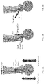
- FIGS. 7A-7C depict a modular glenoid implant 700 similar to implant 600.
- Implant 700 has an articulating surface 702 and a bone contacting surface 704.
- the bearing component 706 of implant 700 defines an articulating surface 702 adapted to articulate with a humeral head, and has an opposing bone contacting surface 704 surface having a first convexity sized and shaped to match or substantially match the concavity of the paleoglenoid.
- An augment 708 of implant 700 has a second convexity sized and shaped to match or substantially match the concavity of the neoglenoid.
- the bearing component 706 may be formed of a biocompatible polymer and the augment component 708 may be formed of a biocompatible metal.
- the metal may be porous, such as porous titanium, to provide for enhanced bone ingrowth.
- the pegs 710, 712 extending from bearing component 706 include a base 720, 722 and a body portion.
- Pegs 710, 712 may be substantially similar or identical to pegs 610, 612 and/or pegs 510, 512, and are thus not described in greater detail herein.
- Augment 708 is a modular component of implant 700.
- a protrusion or platform 742 extends from bearing component 706.
- Platform 742 is preferably integral with bearing component 706.
- Platform 742 may include apertures 744 configured to receive a protrusion and/or collet portion 746 of augment 708, as described below.
- Augment 708 includes a corresponding recess 748 configured to receive platform 742. Augment 708 further includes bores 740, which align with apertures 744 on platform 742 when platform 742 is received by the recess in augment 708. Extending from augment 708 along the longitudinal axis of bores 740 are protrusions or collets 746. Bores 740 at least partially extend through collets 746. Bore 740 has a first diameter at a portion closest to bone contacting surface 704. A shoulder or step may be included within bore 740, thereby creating a smaller diameter for the remainder of the bore. The portion of the bore with the smaller diameter may include threads that match a threaded portion 734 of set screw, peg, protrusion, or anchor 714. Set screws 714 are of a longitudinal length that allows the set screws to act as an anchor, peg, or protrusion.
- the set screws 714 are not integral to augment 708. However, in some embodiments, at least one set screw 714 may be integral with augment 708. Set screws 714 are intended to stabilize the augment against the neoglenoid cortical wall and provide a coupling mechanism for augment 708 and bearing component 706. Set screws 714 may be formed of biocompatible metal, such as titanium, and may be a porous metal, including porous titanium, to provide for enhanced bone ingrowth.
- Set screws 714 may be generally cylindrical with a body, a coupling portion 734, and a drive portion 736.
- the body portion may be a generally solid portion, such that there is a smooth surface, and a portion with pointed edges creating the shape of a cross or starburst.
- the portion with pointed edges creating the shape of a cross or starburst may facilitate a user in gripping the set screws 714 such that set screws 714 can be rotated and screwed into threads to couple to the bearing component 706.
- Coupling portion 734 of set screws 714 includes a threaded portion.
- a portion of bore 740 includes corresponding threads to receive coupling portion 734.
- Driving portion 736 may be a tapered conical shape.
- the driving portion 736 tapers along the longitudinal axis of set screw 714.
- Driving portion is the leading portion inserted into bore 740.
- Driving portion 736 passes through bore 740 and into collet 746 of augment 708.
- the expansion of collet 746 causes a press-fit or friction-fit interference between collet 746 and bearing component 706. This fit provides a high degree of strength between the metal augment 708 and polymer bearing component 706.
- the metal collet 746 when expanded, will be driven into the polymer bearing component 706 thereby coupling augment 708 to polymer component 706.
- implants 600, 700 include modular components, such that augments 608, 708 can be interchanged with a similarly designed augment having a different size and/or convexity. This may allow users to choose the augment that will best suit the needs of a particular patient. For example, if there is a large amount of wear or degradation, such that the concavity of the neoglenoid is large, an augment having a large convexity matching or substantially matching the concavity may be provided. This allows for a more patient specific fit.
Claims (15)
- Implant glénoïde (200) comprenant :une surface d'articulation (202) ;une surface de contact osseux (204) opposée à la surface d'articulation, la surface de contact osseux (204) ayant une première partie (206) et une seconde partie (208) ; etau moins un premier ancrage (210) s'étendant à partir de la première partie (206) de la surface de contact osseux (204) et ayant une première surface sensiblement plane (212), et au moins un second ancrage (220) s'étendant à partir de la seconde partie (208) de la surface de contact osseux (204) et ayant une seconde surface sensiblement plane (222),dans lequel les première et seconde surfaces sensiblement planes (212, 222) sont parallèles l'une à l'autre, et sont sensiblement orthogonales à un troisième axe s'étendant dans une direction latéro-antérieure à médio-postérieure ; l'implant glénoïde étant caractérisé en ce que :
la première partie (206) de la surface de contact osseux (204) a une première convexité configurée pour venir au contact d'une partie antérieure de la cavité glénoïde, la seconde partie (208) de la surface de contact osseux (204) a une seconde convexité configurée pour venir au contact d'une partie postérieure de la cavité glénoïde, la première convexité étant différente de la seconde convexité. - Implant selon la revendication 1, dans lequel le troisième axe est sensiblement tangentiel à la seconde partie (208) de la surface de contact osseux (204).
- Implant selon les revendications 1 ou 2, dans lequel le premier ancrage (210) et le second ancrage (220) sont des coins.
- Implant selon la revendication 3, dans lequel les coins ont une première largeur au niveau d'une partie la plus proche de la surface de contact osseux (204) et une seconde largeur inférieure à la première largeur au niveau d'une partie à l'écart de la surface de contact osseux (204), la première largeur diminuant jusqu'à la seconde largeur.
- Implant selon les revendications 3 ou 4, dans lequel les coins ont une première largeur au niveau d'une partie antérieure et une seconde largeur au niveau d'une partie postérieure, la première largeur diminuant le long du troisième axe jusqu'à la seconde largeur.
- Implant selon l'une quelconque des revendications précédentes, dans lequel les première et seconde surfaces sensiblement planes (212, 222) s'étendent à l'écart de la surface de contact osseux (204) transversale au troisième axe.
- Implant selon l'une quelconque des revendications précédentes, dans lequel le premier ancrage (210) et le second ancrage (220) s'alignent le long d'un axe sensiblement parallèle au troisième axe.
- Implant selon l'une quelconque des revendications précédentes, dans lequel au moins un premier ancrage (210) inclut trois premiers ancrages.
- Implant selon l'une quelconque des revendications précédentes, dans lequel l'au moins un second ancrage (220) inclut deux seconds ancrages.
- Implant selon l'une quelconque des revendications précédentes, dans lequel :la surface de contact osseux (204) inclut un bord périmétrique externe (230) ;les première et seconde parties (206, 208) se rencontrent le long d'une ligne de transition (240) ;le premier ancrage (210) est positionné au niveau d'une première distance à partir du bord périmétrique externe (230) et de la ligne de transition (240) ; etle second bord (220) est positionné au niveau d'une seconde distance à partir du bord périmétrique externe (230) et de la ligne de transition (240).
- Implant selon la revendication 10, dans lequel la ligne de transition (240) est une ligne incurvée.
- Implant selon l'une quelconque des revendications précédentes, comprenant en outre :un composant d'appui (506, 606) définissant la surface d'articulation (502, 602), dans lequel le composant d'appui (506, 606) se compose d'un polymère ; etun composant d'augmentation (508, 608), dans lequel le composant d'augmentation (508, 608) se compose d'un métal, le composant d'augmentation (508, 608) formant au moins une partie de la surface de contact osseux (504, 604) .
- Implant selon la revendication 12, dans lequel le composant d'augmentation (608) est modulaire de telle sorte que le composant d'augmentation (608) peut être couplé de manière amovible au composant d'appui (606).
- Implant selon la revendication 13, dans lequel le composant d'augmentation (608) inclut une cavité (646) et le composant d'appui (606) inclut une saillie (642) destinée à être reçue à l'intérieur de celle-ci.
- Implant selon l'une quelconque des revendications 12 à 14, dans lequel le composant d'appui (506) est surmoulé sur le composant d'augmentation (508).
Priority Applications (1)
| Application Number | Priority Date | Filing Date | Title |
|---|---|---|---|
| EP22171189.8A EP4052663A1 (fr) | 2019-07-12 | 2020-07-09 | Conception glénoïdienne augmentée |
Applications Claiming Priority (1)
| Application Number | Priority Date | Filing Date | Title |
|---|---|---|---|
| US201962873266P | 2019-07-12 | 2019-07-12 |
Related Child Applications (1)
| Application Number | Title | Priority Date | Filing Date |
|---|---|---|---|
| EP22171189.8A Division EP4052663A1 (fr) | 2019-07-12 | 2020-07-09 | Conception glénoïdienne augmentée |
Publications (2)
| Publication Number | Publication Date |
|---|---|
| EP3763301A1 EP3763301A1 (fr) | 2021-01-13 |
| EP3763301B1 true EP3763301B1 (fr) | 2022-05-04 |
Family
ID=71575058
Family Applications (2)
| Application Number | Title | Priority Date | Filing Date |
|---|---|---|---|
| EP22171189.8A Pending EP4052663A1 (fr) | 2019-07-12 | 2020-07-09 | Conception glénoïdienne augmentée |
| EP20185044.3A Active EP3763301B1 (fr) | 2019-07-12 | 2020-07-09 | Conception glénoïdienne augmentée |
Family Applications Before (1)
| Application Number | Title | Priority Date | Filing Date |
|---|---|---|---|
| EP22171189.8A Pending EP4052663A1 (fr) | 2019-07-12 | 2020-07-09 | Conception glénoïdienne augmentée |
Country Status (3)
| Country | Link |
|---|---|
| US (2) | US11285009B2 (fr) |
| EP (2) | EP4052663A1 (fr) |
| AU (1) | AU2020204539A1 (fr) |
Family Cites Families (58)
| Publication number | Priority date | Publication date | Assignee | Title |
|---|---|---|---|---|
| US3559514A (en) | 1968-06-17 | 1971-02-02 | Russell Brownfield | Reamers for electrical line conduits, and the like |
| US5203653A (en) | 1991-12-30 | 1993-04-20 | Pfizer Hospital Products Group, Inc. | Reamer for shaping bone sockets |
| US5591170A (en) | 1994-10-14 | 1997-01-07 | Genesis Orthopedics | Intramedullary bone cutting saw |
| US5800551A (en) | 1997-03-10 | 1998-09-01 | Biomet, Inc. | Apparatus and method for shoulder arthroplasty |
| US5919195A (en) | 1998-01-20 | 1999-07-06 | Johnson & Johnson Professional, Inc. | Oblong acetabular component instrumentation |
| US20030220646A1 (en) | 2002-05-23 | 2003-11-27 | Thelen Sarah L. | Method and apparatus for reducing femoral fractures |
| US6699289B2 (en) | 2001-12-31 | 2004-03-02 | Depuy Orthopaedics, Inc. | Augmented glenoid component having an interrupted surface and associated method for securing the augmented glenoid component to a glenoid surface of a scapula |
| AU2002242659A1 (en) | 2002-01-11 | 2003-07-24 | Waldemar Link (Gmbh And Co.) | Surgical instrument for routing out the hip socket |
| KR100964762B1 (ko) | 2002-02-08 | 2010-06-21 | 구르샤란 싱 차나 | 외과수술장치 및 그 사용방법 |
| US20030176868A1 (en) | 2002-02-22 | 2003-09-18 | Pepper John R. | Long bone reaming apparatus and method |
| US20030163135A1 (en) | 2002-02-22 | 2003-08-28 | Hathaway Ray W. | Orthopeadic reamer with see-through viewing windows |
| US6949101B2 (en) | 2002-03-29 | 2005-09-27 | Depuy Orthopaedics, Inc. | Medical instrument for milling a curved path in bone and procedure |
| WO2003092513A1 (fr) | 2002-04-30 | 2003-11-13 | Precimed S.A. | Porte-fraise pour chirurgie des articulations avec effraction minimale |
| US7473254B2 (en) | 2002-05-10 | 2009-01-06 | Precimed S.A. | Pivoting bone reamer for minimally invasive joint surgery |
| US6997928B1 (en) | 2002-06-10 | 2006-02-14 | Wright Medical Technology, Inc. | Apparatus for and method of providing a hip replacement |
| US7217271B2 (en) | 2002-09-13 | 2007-05-15 | Symmetry Medical, Inc. | Orthopaedic reamer driver for minimally invasive surgery |
| US7572259B2 (en) | 2002-09-16 | 2009-08-11 | Greatbatch Ltd. | Inset acetabular reamer coupling |
| US7749227B2 (en) | 2003-04-28 | 2010-07-06 | Greatbatch Medical S.A. | Precision assembleable surgical tool handle with limited-play interconnect mechanism |
| US7503921B2 (en) | 2004-01-13 | 2009-03-17 | Symmetry Medical, Inc. | Variable angle orthopaedic reamer driver |
| US7294133B2 (en) | 2004-06-03 | 2007-11-13 | Zimmer Technology, Inc. | Method and apparatus for preparing a glenoid surface |
| US20060015110A1 (en) | 2004-07-15 | 2006-01-19 | Pepper John R | Cutting device |
| US7892287B2 (en) | 2004-09-27 | 2011-02-22 | Depuy Products, Inc. | Glenoid augment and associated method |
| US7927335B2 (en) | 2004-09-27 | 2011-04-19 | Depuy Products, Inc. | Instrument for preparing an implant support surface and associated method |
| US7922769B2 (en) | 2004-09-27 | 2011-04-12 | Depuy Products, Inc. | Modular glenoid prosthesis and associated method |
| US20070038303A1 (en) | 2006-08-15 | 2007-02-15 | Ebi, L.P. | Foot/ankle implant and associated method |
| GB0503529D0 (en) | 2005-02-21 | 2005-03-30 | Smith & Nephew Inc | Medical device |
| US20070038302A1 (en) | 2005-08-15 | 2007-02-15 | Biomet Manufacturing Corp. | Method and apparatus for the preparation of an inlaid glenoid |
| US20110004215A1 (en) | 2005-09-12 | 2011-01-06 | Bradley James P | Labrum retracting burr |
| US20070093840A1 (en) | 2005-10-06 | 2007-04-26 | Pacelli Nicolas J | Flexible shaft |
| US7967868B2 (en) * | 2007-04-17 | 2011-06-28 | Biomet Manufacturing Corp. | Patient-modified implant and associated method |
| FR2911773B1 (fr) | 2007-01-30 | 2009-03-27 | Tornier Sas | Methode et ensemble d'instrumentation chirurgicale pour poser une prothese totale d'epaule inversee,et prothese correspondante |
| GB0725024D0 (en) | 2007-12-21 | 2008-01-30 | Depuy Int Ltd | Instrument for removing tissue |
| US8241289B2 (en) | 2008-04-28 | 2012-08-14 | Depuy (Ireland) | Manual glenoid reamer |
| US8771275B2 (en) | 2008-09-23 | 2014-07-08 | Ping Xie | Device for shaping object with a profile of at least a partial sphere |
| US9545311B2 (en) | 2009-03-05 | 2017-01-17 | Tornier, Inc. | Glenoid implant anchor post |
| US9241720B2 (en) | 2009-07-10 | 2016-01-26 | Peter Forsell | Hip joint instrument and method |
| US8721727B2 (en) | 2009-11-24 | 2014-05-13 | Tornier Sas | Glenoid component with offset center and associated methods |
| FR2955247B1 (fr) | 2010-01-21 | 2013-04-26 | Tornier Sa | Composant glenoidien de prothese d'epaule |
| US8475460B1 (en) | 2010-02-23 | 2013-07-02 | Greatbatch Medical S.A. | Angled reamer spindle for minimally invasive hip replacement surgery |
| US8657833B2 (en) | 2010-03-05 | 2014-02-25 | Greatbatch Medical S.A. | Double offset surgical tool handle assembly to provide greater offset from the coronal plane |
| US20120059359A1 (en) | 2010-03-05 | 2012-03-08 | Greatbatch Medical S.A. | Double Offset Surgical Tool Handle Assembly Having A Locking Linkage Aligned Along Two Different Planes |
| US9408652B2 (en) | 2010-04-27 | 2016-08-09 | Tornier Sas | Intra-articular joint replacement and method |
| WO2011149590A1 (fr) * | 2010-05-27 | 2011-12-01 | Synthes Usa, Llc | Allo-prothèse de cavité articulaire |
| US9078672B1 (en) | 2010-11-05 | 2015-07-14 | Greatbatch Medical S.A. | Carbon reamer handle |
| FR2967046A1 (fr) | 2010-11-10 | 2012-05-11 | Tornier Sa | Fraiseuse orthopedique de preparation osseuse, en particulier de preparation glenoidienne |
| US8486076B2 (en) | 2011-01-28 | 2013-07-16 | DePuy Synthes Products, LLC | Oscillating rasp for use in an orthopaedic surgical procedure |
| FR2971144A1 (fr) * | 2011-02-08 | 2012-08-10 | Tornier Sa | Implant glenoidien pour prothese d'epaule et kit chirurgical |
| US9820758B2 (en) | 2011-03-18 | 2017-11-21 | DePuy Synthes Products, Inc. | Combination reamer/drill bit for shoulder arthoplasty |
| US10350078B2 (en) * | 2012-06-27 | 2019-07-16 | Arthrosurface, Inc. | Devices, apparatuses, kits, and methods for repair of articular surface and/or articular rim |
| US8876907B2 (en) * | 2012-07-26 | 2014-11-04 | Howmedica Osteonics Corp. | Cement pressurizing glenoid |
| US9775716B2 (en) * | 2013-03-11 | 2017-10-03 | Catalyst Orthoscience Inc. | Glenoid arthroplasty |
| US20150150688A1 (en) * | 2013-12-03 | 2015-06-04 | Biomet Manufacturing, Llc | Patient-Specific Glenoid Implant |
| US10028838B2 (en) * | 2014-06-30 | 2018-07-24 | Tornier, Inc. | Augmented glenoid components and devices for implanting the same |
| CN113143394A (zh) | 2015-04-24 | 2021-07-23 | 拜欧米特制造有限责任公司 | 患者特异性增强关节盂系统 |
| US11141276B2 (en) * | 2017-01-20 | 2021-10-12 | Biomet Manufacturing, Llc | Modular augment component |
| US11510785B2 (en) * | 2017-04-25 | 2022-11-29 | Biomet Manufacturing, Llc | Augmented glenoid with groove |
| EP3403617B1 (fr) * | 2017-05-19 | 2020-03-18 | Tornier | Insert d'augmentation, prothèse d'épaule et kit comprenant l'insert d'augmentation |
| US10555816B1 (en) * | 2019-02-12 | 2020-02-11 | Shoulder Innovations, Llc | Systems and methods of a glenoid component |
-
2020
- 2020-07-07 AU AU2020204539A patent/AU2020204539A1/en active Pending
- 2020-07-09 EP EP22171189.8A patent/EP4052663A1/fr active Pending
- 2020-07-09 EP EP20185044.3A patent/EP3763301B1/fr active Active
- 2020-07-10 US US16/925,809 patent/US11285009B2/en active Active
-
2022
- 2022-01-27 US US17/585,889 patent/US20220142787A1/en active Pending
Also Published As
| Publication number | Publication date |
|---|---|
| US20220142787A1 (en) | 2022-05-12 |
| US11285009B2 (en) | 2022-03-29 |
| EP4052663A1 (fr) | 2022-09-07 |
| US20210007858A1 (en) | 2021-01-14 |
| EP3763301A1 (fr) | 2021-01-13 |
| AU2020204539A1 (en) | 2021-01-28 |
Similar Documents
| Publication | Publication Date | Title |
|---|---|---|
| EP1323395B1 (fr) | Elément glénoidien renforcé ayant une surface interrompue | |
| US9937058B2 (en) | Prosthetic implant and method of implantation | |
| US9579208B2 (en) | Modular radial head prosthesis | |
| US7670382B2 (en) | Extended articular surface resurfacing head | |
| CA2560960C (fr) | Implant allogenique | |
| US8366781B2 (en) | Modular prosthesis and use thereof for replacing a radial head | |
| US9439784B2 (en) | Modular radial head prosthesis | |
| US20060155380A1 (en) | Modular femoral component for a total knee joint replacement for minimally invasive implantation | |
| US20120209391A1 (en) | Modular prosthesis | |
| US20110093077A1 (en) | Intervertebral implant with joint elements carried by universal joint | |
| EP2298246A1 (fr) | Prothèse articulaire avec une tête positionable | |
| US20240041615A1 (en) | Tibial tray inserter | |
| EP3763301B1 (fr) | Conception glénoïdienne augmentée | |
| US20210275314A1 (en) | Glenoid Implant with Additively Manufactured Fixation Posts |
Legal Events
| Date | Code | Title | Description |
|---|---|---|---|
| PUAI | Public reference made under article 153(3) epc to a published international application that has entered the european phase |
Free format text: ORIGINAL CODE: 0009012 |
|
| STAA | Information on the status of an ep patent application or granted ep patent |
Free format text: STATUS: REQUEST FOR EXAMINATION WAS MADE |
|
| 17P | Request for examination filed |
Effective date: 20200709 |
|
| AK | Designated contracting states |
Kind code of ref document: A1 Designated state(s): AL AT BE BG CH CY CZ DE DK EE ES FI FR GB GR HR HU IE IS IT LI LT LU LV MC MK MT NL NO PL PT RO RS SE SI SK SM TR |
|
| AX | Request for extension of the european patent |
Extension state: BA ME |
|
| GRAP | Despatch of communication of intention to grant a patent |
Free format text: ORIGINAL CODE: EPIDOSNIGR1 |
|
| STAA | Information on the status of an ep patent application or granted ep patent |
Free format text: STATUS: GRANT OF PATENT IS INTENDED |
|
| RIC1 | Information provided on ipc code assigned before grant |
Ipc: A61F 2/38 20060101ALI20211228BHEP Ipc: A61B 17/15 20060101AFI20211228BHEP |
|
| INTG | Intention to grant announced |
Effective date: 20220127 |
|
| RAP3 | Party data changed (applicant data changed or rights of an application transferred) |
Owner name: HOWMEDICA OSTEONICS CORP. |
|
| INTG | Intention to grant announced |
Effective date: 20220201 |
|
| GRAS | Grant fee paid |
Free format text: ORIGINAL CODE: EPIDOSNIGR3 |
|
| GRAA | (expected) grant |
Free format text: ORIGINAL CODE: 0009210 |
|
| STAA | Information on the status of an ep patent application or granted ep patent |
Free format text: STATUS: THE PATENT HAS BEEN GRANTED |
|
| AK | Designated contracting states |
Kind code of ref document: B1 Designated state(s): AL AT BE BG CH CY CZ DE DK EE ES FI FR GB GR HR HU IE IS IT LI LT LU LV MC MK MT NL NO PL PT RO RS SE SI SK SM TR |
|
| REG | Reference to a national code |
Ref country code: GB Ref legal event code: FG4D |
|
| REG | Reference to a national code |
Ref country code: CH Ref legal event code: EP |
|
| REG | Reference to a national code |
Ref country code: AT Ref legal event code: REF Ref document number: 1488183 Country of ref document: AT Kind code of ref document: T Effective date: 20220515 |
|
| REG | Reference to a national code |
Ref country code: DE Ref legal event code: R096 Ref document number: 602020002983 Country of ref document: DE |
|
| REG | Reference to a national code |
Ref country code: IE Ref legal event code: FG4D |
|
| REG | Reference to a national code |
Ref country code: LT Ref legal event code: MG9D |
|
| REG | Reference to a national code |
Ref country code: NL Ref legal event code: MP Effective date: 20220504 |
|
| REG | Reference to a national code |
Ref country code: AT Ref legal event code: MK05 Ref document number: 1488183 Country of ref document: AT Kind code of ref document: T Effective date: 20220504 |
|
| PG25 | Lapsed in a contracting state [announced via postgrant information from national office to epo] |
Ref country code: SE Free format text: LAPSE BECAUSE OF FAILURE TO SUBMIT A TRANSLATION OF THE DESCRIPTION OR TO PAY THE FEE WITHIN THE PRESCRIBED TIME-LIMIT Effective date: 20220504 Ref country code: PT Free format text: LAPSE BECAUSE OF FAILURE TO SUBMIT A TRANSLATION OF THE DESCRIPTION OR TO PAY THE FEE WITHIN THE PRESCRIBED TIME-LIMIT Effective date: 20220905 Ref country code: NO Free format text: LAPSE BECAUSE OF FAILURE TO SUBMIT A TRANSLATION OF THE DESCRIPTION OR TO PAY THE FEE WITHIN THE PRESCRIBED TIME-LIMIT Effective date: 20220804 Ref country code: NL Free format text: LAPSE BECAUSE OF FAILURE TO SUBMIT A TRANSLATION OF THE DESCRIPTION OR TO PAY THE FEE WITHIN THE PRESCRIBED TIME-LIMIT Effective date: 20220504 Ref country code: LT Free format text: LAPSE BECAUSE OF FAILURE TO SUBMIT A TRANSLATION OF THE DESCRIPTION OR TO PAY THE FEE WITHIN THE PRESCRIBED TIME-LIMIT Effective date: 20220504 Ref country code: HR Free format text: LAPSE BECAUSE OF FAILURE TO SUBMIT A TRANSLATION OF THE DESCRIPTION OR TO PAY THE FEE WITHIN THE PRESCRIBED TIME-LIMIT Effective date: 20220504 Ref country code: GR Free format text: LAPSE BECAUSE OF FAILURE TO SUBMIT A TRANSLATION OF THE DESCRIPTION OR TO PAY THE FEE WITHIN THE PRESCRIBED TIME-LIMIT Effective date: 20220805 Ref country code: FI Free format text: LAPSE BECAUSE OF FAILURE TO SUBMIT A TRANSLATION OF THE DESCRIPTION OR TO PAY THE FEE WITHIN THE PRESCRIBED TIME-LIMIT Effective date: 20220504 Ref country code: BG Free format text: LAPSE BECAUSE OF FAILURE TO SUBMIT A TRANSLATION OF THE DESCRIPTION OR TO PAY THE FEE WITHIN THE PRESCRIBED TIME-LIMIT Effective date: 20220804 Ref country code: AT Free format text: LAPSE BECAUSE OF FAILURE TO SUBMIT A TRANSLATION OF THE DESCRIPTION OR TO PAY THE FEE WITHIN THE PRESCRIBED TIME-LIMIT Effective date: 20220504 |
|
| PG25 | Lapsed in a contracting state [announced via postgrant information from national office to epo] |
Ref country code: RS Free format text: LAPSE BECAUSE OF FAILURE TO SUBMIT A TRANSLATION OF THE DESCRIPTION OR TO PAY THE FEE WITHIN THE PRESCRIBED TIME-LIMIT Effective date: 20220504 Ref country code: PL Free format text: LAPSE BECAUSE OF FAILURE TO SUBMIT A TRANSLATION OF THE DESCRIPTION OR TO PAY THE FEE WITHIN THE PRESCRIBED TIME-LIMIT Effective date: 20220504 Ref country code: LV Free format text: LAPSE BECAUSE OF FAILURE TO SUBMIT A TRANSLATION OF THE DESCRIPTION OR TO PAY THE FEE WITHIN THE PRESCRIBED TIME-LIMIT Effective date: 20220504 Ref country code: IS Free format text: LAPSE BECAUSE OF FAILURE TO SUBMIT A TRANSLATION OF THE DESCRIPTION OR TO PAY THE FEE WITHIN THE PRESCRIBED TIME-LIMIT Effective date: 20220904 |
|
| PG25 | Lapsed in a contracting state [announced via postgrant information from national office to epo] |
Ref country code: SM Free format text: LAPSE BECAUSE OF FAILURE TO SUBMIT A TRANSLATION OF THE DESCRIPTION OR TO PAY THE FEE WITHIN THE PRESCRIBED TIME-LIMIT Effective date: 20220504 Ref country code: SK Free format text: LAPSE BECAUSE OF FAILURE TO SUBMIT A TRANSLATION OF THE DESCRIPTION OR TO PAY THE FEE WITHIN THE PRESCRIBED TIME-LIMIT Effective date: 20220504 Ref country code: RO Free format text: LAPSE BECAUSE OF FAILURE TO SUBMIT A TRANSLATION OF THE DESCRIPTION OR TO PAY THE FEE WITHIN THE PRESCRIBED TIME-LIMIT Effective date: 20220504 Ref country code: ES Free format text: LAPSE BECAUSE OF FAILURE TO SUBMIT A TRANSLATION OF THE DESCRIPTION OR TO PAY THE FEE WITHIN THE PRESCRIBED TIME-LIMIT Effective date: 20220504 Ref country code: EE Free format text: LAPSE BECAUSE OF FAILURE TO SUBMIT A TRANSLATION OF THE DESCRIPTION OR TO PAY THE FEE WITHIN THE PRESCRIBED TIME-LIMIT Effective date: 20220504 Ref country code: DK Free format text: LAPSE BECAUSE OF FAILURE TO SUBMIT A TRANSLATION OF THE DESCRIPTION OR TO PAY THE FEE WITHIN THE PRESCRIBED TIME-LIMIT Effective date: 20220504 Ref country code: CZ Free format text: LAPSE BECAUSE OF FAILURE TO SUBMIT A TRANSLATION OF THE DESCRIPTION OR TO PAY THE FEE WITHIN THE PRESCRIBED TIME-LIMIT Effective date: 20220504 |
|
| REG | Reference to a national code |
Ref country code: DE Ref legal event code: R097 Ref document number: 602020002983 Country of ref document: DE |
|
| PG25 | Lapsed in a contracting state [announced via postgrant information from national office to epo] |
Ref country code: MC Free format text: LAPSE BECAUSE OF FAILURE TO SUBMIT A TRANSLATION OF THE DESCRIPTION OR TO PAY THE FEE WITHIN THE PRESCRIBED TIME-LIMIT Effective date: 20220504 |
|
| PLBE | No opposition filed within time limit |
Free format text: ORIGINAL CODE: 0009261 |
|
| STAA | Information on the status of an ep patent application or granted ep patent |
Free format text: STATUS: NO OPPOSITION FILED WITHIN TIME LIMIT |
|
| REG | Reference to a national code |
Ref country code: BE Ref legal event code: MM Effective date: 20220731 |
|
| PG25 | Lapsed in a contracting state [announced via postgrant information from national office to epo] |
Ref country code: AL Free format text: LAPSE BECAUSE OF FAILURE TO SUBMIT A TRANSLATION OF THE DESCRIPTION OR TO PAY THE FEE WITHIN THE PRESCRIBED TIME-LIMIT Effective date: 20220504 |
|
| 26N | No opposition filed |
Effective date: 20230207 |
|
| PG25 | Lapsed in a contracting state [announced via postgrant information from national office to epo] |
Ref country code: LU Free format text: LAPSE BECAUSE OF NON-PAYMENT OF DUE FEES Effective date: 20220709 |
|
| PG25 | Lapsed in a contracting state [announced via postgrant information from national office to epo] |
Ref country code: SI Free format text: LAPSE BECAUSE OF FAILURE TO SUBMIT A TRANSLATION OF THE DESCRIPTION OR TO PAY THE FEE WITHIN THE PRESCRIBED TIME-LIMIT Effective date: 20220504 Ref country code: BE Free format text: LAPSE BECAUSE OF NON-PAYMENT OF DUE FEES Effective date: 20220731 |
|
| P01 | Opt-out of the competence of the unified patent court (upc) registered |
Effective date: 20230522 |
|
| PGFP | Annual fee paid to national office [announced via postgrant information from national office to epo] |
Ref country code: IE Payment date: 20230606 Year of fee payment: 4 Ref country code: FR Payment date: 20230620 Year of fee payment: 4 |
|
| PGFP | Annual fee paid to national office [announced via postgrant information from national office to epo] |
Ref country code: IT Payment date: 20230731 Year of fee payment: 4 |
|
| PGFP | Annual fee paid to national office [announced via postgrant information from national office to epo] |
Ref country code: DE Payment date: 20230531 Year of fee payment: 4 |
|
| REG | Reference to a national code |
Ref country code: CH Ref legal event code: PL |