EP3763003B1 - Leitungsgekühlter slablaser - Google Patents
Leitungsgekühlter slablaser Download PDFInfo
- Publication number
- EP3763003B1 EP3763003B1 EP19710970.5A EP19710970A EP3763003B1 EP 3763003 B1 EP3763003 B1 EP 3763003B1 EP 19710970 A EP19710970 A EP 19710970A EP 3763003 B1 EP3763003 B1 EP 3763003B1
- Authority
- EP
- European Patent Office
- Prior art keywords
- laser
- slab
- elongated
- discharge
- recited
- Prior art date
- Legal status (The legal status is an assumption and is not a legal conclusion. Google has not performed a legal analysis and makes no representation as to the accuracy of the status listed.)
- Active
Links
Images



Classifications
-
- H—ELECTRICITY
- H01—ELECTRIC ELEMENTS
- H01S—DEVICES USING THE PROCESS OF LIGHT AMPLIFICATION BY STIMULATED EMISSION OF RADIATION [LASER] TO AMPLIFY OR GENERATE LIGHT; DEVICES USING STIMULATED EMISSION OF ELECTROMAGNETIC RADIATION IN WAVE RANGES OTHER THAN OPTICAL
- H01S3/00—Lasers, i.e. devices using stimulated emission of electromagnetic radiation in the infrared, visible or ultraviolet wave range
- H01S3/02—Constructional details
- H01S3/03—Constructional details of gas laser discharge tubes
- H01S3/0315—Waveguide lasers
-
- H—ELECTRICITY
- H01—ELECTRIC ELEMENTS
- H01S—DEVICES USING THE PROCESS OF LIGHT AMPLIFICATION BY STIMULATED EMISSION OF RADIATION [LASER] TO AMPLIFY OR GENERATE LIGHT; DEVICES USING STIMULATED EMISSION OF ELECTROMAGNETIC RADIATION IN WAVE RANGES OTHER THAN OPTICAL
- H01S3/00—Lasers, i.e. devices using stimulated emission of electromagnetic radiation in the infrared, visible or ultraviolet wave range
- H01S3/02—Constructional details
- H01S3/03—Constructional details of gas laser discharge tubes
- H01S3/0305—Selection of materials for the tube or the coatings thereon
-
- H—ELECTRICITY
- H01—ELECTRIC ELEMENTS
- H01S—DEVICES USING THE PROCESS OF LIGHT AMPLIFICATION BY STIMULATED EMISSION OF RADIATION [LASER] TO AMPLIFY OR GENERATE LIGHT; DEVICES USING STIMULATED EMISSION OF ELECTROMAGNETIC RADIATION IN WAVE RANGES OTHER THAN OPTICAL
- H01S3/00—Lasers, i.e. devices using stimulated emission of electromagnetic radiation in the infrared, visible or ultraviolet wave range
- H01S3/02—Constructional details
- H01S3/03—Constructional details of gas laser discharge tubes
- H01S3/038—Electrodes, e.g. special shape, configuration or composition
- H01S3/0385—Shape
-
- H—ELECTRICITY
- H01—ELECTRIC ELEMENTS
- H01S—DEVICES USING THE PROCESS OF LIGHT AMPLIFICATION BY STIMULATED EMISSION OF RADIATION [LASER] TO AMPLIFY OR GENERATE LIGHT; DEVICES USING STIMULATED EMISSION OF ELECTROMAGNETIC RADIATION IN WAVE RANGES OTHER THAN OPTICAL
- H01S3/00—Lasers, i.e. devices using stimulated emission of electromagnetic radiation in the infrared, visible or ultraviolet wave range
- H01S3/02—Constructional details
- H01S3/04—Arrangements for thermal management
- H01S3/0404—Air- or gas cooling, e.g. by dry nitrogen
-
- H—ELECTRICITY
- H01—ELECTRIC ELEMENTS
- H01S—DEVICES USING THE PROCESS OF LIGHT AMPLIFICATION BY STIMULATED EMISSION OF RADIATION [LASER] TO AMPLIFY OR GENERATE LIGHT; DEVICES USING STIMULATED EMISSION OF ELECTROMAGNETIC RADIATION IN WAVE RANGES OTHER THAN OPTICAL
- H01S3/00—Lasers, i.e. devices using stimulated emission of electromagnetic radiation in the infrared, visible or ultraviolet wave range
- H01S3/02—Constructional details
- H01S3/04—Arrangements for thermal management
- H01S3/0405—Conductive cooling, e.g. by heat sinks or thermo-electric elements
-
- H—ELECTRICITY
- H01—ELECTRIC ELEMENTS
- H01S—DEVICES USING THE PROCESS OF LIGHT AMPLIFICATION BY STIMULATED EMISSION OF RADIATION [LASER] TO AMPLIFY OR GENERATE LIGHT; DEVICES USING STIMULATED EMISSION OF ELECTROMAGNETIC RADIATION IN WAVE RANGES OTHER THAN OPTICAL
- H01S3/00—Lasers, i.e. devices using stimulated emission of electromagnetic radiation in the infrared, visible or ultraviolet wave range
- H01S3/02—Constructional details
- H01S3/04—Arrangements for thermal management
- H01S3/0407—Liquid cooling, e.g. by water
-
- H—ELECTRICITY
- H01—ELECTRIC ELEMENTS
- H01S—DEVICES USING THE PROCESS OF LIGHT AMPLIFICATION BY STIMULATED EMISSION OF RADIATION [LASER] TO AMPLIFY OR GENERATE LIGHT; DEVICES USING STIMULATED EMISSION OF ELECTROMAGNETIC RADIATION IN WAVE RANGES OTHER THAN OPTICAL
- H01S3/00—Lasers, i.e. devices using stimulated emission of electromagnetic radiation in the infrared, visible or ultraviolet wave range
- H01S3/02—Constructional details
- H01S3/04—Arrangements for thermal management
- H01S3/041—Arrangements for thermal management for gas lasers
-
- H—ELECTRICITY
- H01—ELECTRIC ELEMENTS
- H01S—DEVICES USING THE PROCESS OF LIGHT AMPLIFICATION BY STIMULATED EMISSION OF RADIATION [LASER] TO AMPLIFY OR GENERATE LIGHT; DEVICES USING STIMULATED EMISSION OF ELECTROMAGNETIC RADIATION IN WAVE RANGES OTHER THAN OPTICAL
- H01S3/00—Lasers, i.e. devices using stimulated emission of electromagnetic radiation in the infrared, visible or ultraviolet wave range
- H01S3/14—Lasers, i.e. devices using stimulated emission of electromagnetic radiation in the infrared, visible or ultraviolet wave range characterised by the material used as the active medium
- H01S3/22—Gases
- H01S3/223—Gases the active gas being polyatomic, i.e. containing two or more atoms
- H01S3/2232—Carbon dioxide (CO2) or monoxide [CO]
Definitions
- the present invention relates in general to carbon dioxide (CO 2 ) lasers.
- the invention relates in particular to pulsed CO 2 gas-discharge lasers having a slab configuration.
- CO 2 lasers have been used for decades in industrial processes, wherein the infrared (IR) wavelength and relatively high power of a CO 2 laser is advantageous.
- the lasing medium in a CO 2 laser is a gas-discharge in a gas mixture.
- the gas mixture typically includes 10% to 20% CO 2 and is maintained at less than one atmosphere of pressure.
- the gas mixture is energized to generate the gas-discharge by applying an electric current or a radio-frequency (RF) field between two electrodes.
- RF radio-frequency
- CO 2 lasers can deliver output laser-radiation at infrared wavelengths within a range from about 9 micrometers ( ⁇ m) to about 11 ⁇ m.
- a CO 2 laser may be configured as a waveguide-laser or a slab-laser.
- a waveguide CO 2 laser the gas-discharge is established within a long and comparatively narrow waveguide.
- a laser-resonator is formed around the energized gas mixture by resonator mirrors, located at each end of the waveguide, that direct laser-radiation a longitudinal direction.
- the narrow waveguide constrains one or more laser-radiation modes in two mutually-orthogonal transverse directions.
- Laser-radiation is amplified by stimulated emission during multiple passes through the gas-discharge.
- Such CO 2 waveguide-lasers are capable of providing an inherently high-quality output beam, with good power and wavelength stability, but at relatively low average powers. Typically, at an average power less than about 150 Watts (W).
- Such a waveguide CO 2 laser is described in U.S. Patent No. 6,192,061 and U.S. Patent No. 6,788,722 , each thereof owned by the assignee of the present invention.
- the gas-discharge is established in a volume between flat wave-guiding surfaces of two closely-spaced electrodes.
- a laser-resonator is formed around the energized gas mixture by two resonator mirrors.
- the small gap (“discharge-gap") between the two electrodes defines a waveguide that constrains laser-radiation modes.
- the resonator mirrors typically define an unstable laser-resonator. Laser-radiation exits the unstable laser-resonator as an approximately collimated beam, passing through a hole in one of the resonator mirrors or passing by an outside edge of one of the resonator mirrors.
- Such a slab CO 2 laser is described in U.S. Patent No. 6,256,332 and U.S. Patent No. 7,263,116 , each thereof owned by the assignee of the present invention.
- Such slab CO 2 lasers are capable of delivering an output beam at an average power of up to about 8 kilowatts (kW).
- the output beam inherently has an elongated cross-section. Additional beam-conditioning optics are required to transform the output beam into a more useful cross-sectional shape. For example, a circular shape.
- Slab CO 2 lasers are usually operated in a pulsed mode, delivering pulses of laser-radiation having high peak powers.
- higher average power translates to higher throughput.
- Process efficiency justifies a laser cost that scales with average power.
- the cost scaling results from a need to provide complex cooling arrangements to cope with waste heat generated when operating at high average power.
- a fluid coolant is forced through channels within one or both of the electrodes.
- air is forced through an array of metal fins that are in direct thermal contact with one or both of the electrodes.
- Liquid water is a preferred coolant in many applications because water has a comparatively high heat capacity for efficiently removing substantial waste heat and because fluid-cooling generates less acoustic noise than equivalent forced-air cooling.
- US patent application with publication number US 6,198,758 discloses a laser with a heat transfer system.
- the heat transfer system draws heat from the electrodes which have internal electrode surfaces adjacent to a lasing medium of the laser.
- the heat transfer system utilizes thermally conductive material positioned between external surfaces of the electrodes and internal surfaces of a housing that contains the electrodes and the lasing medium.
- US patent application with publication number US 2005/0105581 discloses a pulsed, Q-switched, waveguide CO 2 laser including a plurality of waveguide channels formed in a block of beryllium oxide ceramic material.
- US patent application with publication number US 2005/0175054 discloses a slab CO 2 laser including spaced-apart elongated slab electrodes. Either one or two ceramic inserts occupy a portion of the width of the electrodes and are in contact with the electrodes.
- pulsed slab CO 2 lasers have been used increasingly in dental applications, including both hard-tissue and soft-tissue operations, where the relatively long IR wavelength permits cutting and coagulation at the same time.
- the relatively high cost of industrial slab-lasers can be prohibitive for a dental practice, where other surgical alternatives are available, albeit less convenient for the surgeon and often more painful for the patient.
- a gas-discharge slab-laser in accordance with the present disclosure comprises a laser-housing, including an elongated hollow extrusion having an interior surface thereof, forming a first elongated electrode.
- a second elongated electrode is located within the elongated extrusion.
- the second elongated electrode is spaced-apart and parallel to the first elongated electrode.
- the spaced-apart first and second elongated electrodes define a discharge-gap of the slab-laser.
- Neither the elongated extrusion nor the second elongated electrode include any fluid-cooling means.
- the first and second elongated electrodes are spaced apart by either first and second elongated ceramic strips, which are laterally-separated and parallel to each other.
- FIG. 1 is a perspective view, schematically illustrating basic features and function of a prior-art CO 2 slab-laser 10.
- Laser 10 includes upper and lower electrodes, 12 and 14 respectively, which each have a rectangular shape. The electrodes are spaced apart and parallel to each other, defining a discharge-gap 16 thereinbetween.
- high-power slab-lasers particularly multi-kilowatt slab-lasers, it is usual to provide direct fluid-cooling through the electrodes, as indicated in the drawing for upper electrode 12.
- Discharge-gap 16 is located in an unstable resonator formed by concave mirrors 18 and 20.
- An RF power source 22 is electrically connected to upper electrode 12.
- Lower electrode 14 is grounded.
- the electrodes are located within a gas-tight housing (not shown) that contains the gas mixture.
- Gas mixtures for CO 2 discharge lasers are well known in the art. Component gases and pressure may vary according to manufacturer preferences and are usually proprietary.
- Output laser-radiation 26 is in the form of an expanding beam having a rectangular cross-section.
- beam-conditioning optics 28 may be provided to convert the beam to a more useful form, such as a collimated beam 30 having an about circular cross-section.
- Beam-conditioning optics are typically located outside the gas-tight housing. Such beam conditioning optics are well-known in the art and a detailed description thereof is not necessary for understanding principles of a CO 2 slab-laser.
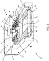
- FIG. 2 is a perspective view, partially cut away, schematically illustrating one example 40 of a CO2 slab-laser.
- Laser 40 has a gas-tight housing 42, including an elongated hollow extrusion 44A, shown partially cut-away to illustrate internal components and arrangements of the laser.
- the extrusion is preferentially made of aluminum and is at electrical ground, as depicted in the drawing.
- An end-plate 46 including one resonator mirror (not visible in the drawing), provides for sealing laser-housing 42 at one end.
- Screw-holes 48 provide for attaching another end-plate and another resonator-mirror (neither shown), for sealing laser-housing 42 at the opposite end.
- Additional screw holes 50 provide for attaching an optional cooling-plate, described in detail further hereinbelow.
- An interior surface 52A of extrusion 44A provides an elongated ground electrode for the laser, which extends along the length of extrusion 44A.
- An elongated live electrode 54A having a lower surface 56A is located within extrusion 44A.
- Live surface 56A is spaced apart from grounded surface 52A by a pair of elongated ceramic strips 58A, which are laterally-separated and parallel to each other.
- Ceramic strips 58A are preferably made of an electrically-insulating ceramic having a relatively high thermal conductivity. For example, made of aluminum nitride (AlN), aluminum oxide (Al 2 O 3 ), or beryllium oxide (BeO). The inventive ceramic strips are highlighted in the drawing by diagonal hatching.
- Spaced-apart grounded surface 52A and live surface 56A define a discharge-gap of laser 40.
- the common height of ceramic strips 58A defines the height of a discharge-volume 60A
- edges 62 of ceramic strips 58A constrain the gas-discharge laterally and thus define a width of the discharge-volume.
- the length of live electrode 54A, the discharge-gap, and edges 62 define discharge-volume 60A.
- the discharge-volume is depicted in cross-section in the drawing and indicated by cross-hatching.
- Grounded surface 52A and live surface 56A are preferably polished.
- a pair of insulator strips 64 electrically isolate live electrode 54A from grounded extrusion 44A.
- Spring strips 66 provided for retaining live electrode 54A in position within the extrusion.
- An electrical feed-through 68 is provided for connecting RF-power to live electrode 54A. Feed-through 68 is electrically connected to live electrode 54A and is electrically isolated from grounded extrusion 44A.
- a plurality of inductors 70 are provided to homogenize the gas-discharge along discharge-volume 60A.
- neither grounded extrusion 44A nor live electrode 54A are provided with any internal fluid-cooling means. This avoids expensive and difficult operations to bore holes within the grounded extrusion and the live electrode, then to fit cooling-tubes within the holes. Such boring and fitting operations would otherwise contribute significantly to the manufacturing cost of the laser.
- Live electrode 54A is conductively cooled, transferring heat to extrusion 44A via ceramic strips 58A.
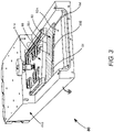
- FIG. 3 is a perspective view, partially cut-away, schematically illustrating another example 80 of a CO2 slab-laser.
- Laser 80 is similar laser 40 of FIG. 2 , except for the manner in which grounded surface 52A and live surface 56A are spaced apart.
- Extrusion 44A of laser 80 is configured identically with extrusion 44A of laser 40 and live electrodes 54A is also identically configured. Accordingly, only sufficient reference numerals are provided in FIG. 3 to describe the different spacing arrangements.
- surfaces 52A and 56A are spaced apart by an elongated ceramic member 82 having two parallel raised edges 84.
- a hollow between ceramic member 82 and grounded surface 52A formed by raised edges 84 defines a discharge-volume 60B.
- a discharge-gap is defined by the common height of the raised edges.
- a width of the discharge-volume is defined by the separation between the raised edges.
- Ceramic member 82 is depicted in FIG. 3 as being in contact with live surface 56A of live electrode 54A. However, ceramic member 82 will function similarly with surface 86 thereof in contact with grounded surface 52A of extrusion 44A. A hollow between ceramic member 82 and live surface 56A formed by raised edges 84 will then define the discharge-volume in this arrangement.
- FIG. 4 is a perspective view, partially cut-away, schematically illustrating yet another example 90 of a CO2 slab-laser.
- Laser 90 is similar to laser 40 of FIG. 2 , except for the manner in which edges of a discharge-volume 60C are defined. Accordingly, only sufficient reference numerals are provided in FIG. 4 to describe these differences.
- extrusion 44B includes a pair of grooves or troughs 92 extending therealong, which are mutually-separated and parallel to each other. Between grooves 92 is a surface 52B, which provides an elongated ground electrode for the laser. A pair of corresponding grooves 94 in elongated live electrode 54B are aligned with grooves 92 in extrusion 44B. Between grooves 94 is a surface 56B of live electrode 54B.
- Ceramic strips 58B are narrower than corresponding ceramic strips 58A of laser 40, such that they do not completely cover grooves 92 and 94. Accordingly, in laser 90, the width of discharge-volume 60C is defined by edges 96 of grooves 92 and edges 98 of grooves 94. A discharge-gap is the defined by the distance between grounded surface 52B and live surface 56B. This arrangement prevents contact between the ceramic spacers and the gas-discharge, thereby avoiding possible erosion of the ceramic spacers by the gas-discharge.
- a variation (not shown) of laser 90 is possible wherein separate ceramic strips 58B are replaced with a single ceramic member similar to ceramic member 82 of laser 80.
- the raised edges of the ceramic member are spaced-apart such that the width of discharge-volume 60C is defined by edges 96 of grooves 92 or edges 98 of grooves 94, as in laser 90.
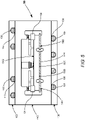
- FIG. 5 is a cross-sectional view, seen generally in the direction 5-5 of FIG. 4 , schematically illustrating two fluid-cooled cooling-plates 100 and 102 attached to respectively lower and upper exterior surfaces of extrusion 44B of laser 90.
- Cooling-plate 100 includes a cooling-fluid conduit 104 having a D-shaped cross-section pressed into a U-shaped groove 106.
- Conduit 104 is preferably continuous, arranged in a serpentine fashion over an area to be cooled.
- Cooling plate 100 is located adjacent to surface 52B, which is the ground electrode.
- Cooling-plate 102 includes a cooling-fluid conduit 108 having a D-shaped cross-section pressed into a U-shaped groove 110.
- Conduit 108 is also preferably a continuous and arranged in a serpentine fashion. Cooling-plate 102 provides additional cooling of extrusion 44B.
- a common cooling fluid is water, often with additives to prevent corrosion and freezing.
- An advantage of using separate cooling-plates rather than providing direct fluid-cooling within extrusion 44B is that is fabricating cooling-plates 100 and 102 is much simpler that machining a similar serpentine cooling path within extrusion 44B. Further, should any corrosion or other damage occur to the conduit, the conduit could be replaced quickly and easily. If necessary, it would be even quicker to exchange the entire cooling-plate.
- Cooling-plates such as cooling-plates 100 and 102, may optionally be attached to any embodiment of slab-laser in accordance with the present invention.
- One or both plates may be advantageous, depending on the power applied to the gas-discharge and the efficiency of the slab-laser.
- Cooling-plate 100 will generally be most effective in conductively cooling the live electrode, because of a relatively short and unrestricted thermal path from the live electrode through the ceramic spacers and the extrusion.
- FIG. 6 is a perspective view, cut away, schematically illustrating still a preferred embodiment 120 of a CO 2 slab-laser in accordance with the present invention.
- Laser 120 is similar to laser 40 of FIG. 2 , except that each ceramic strip is formed by a plurality of ceramic segments 58C.
- live electrode 54A and all the elements above it have been omitted for clarity of illustration.
- Neighboring ceramic segments 58C are slightly separated from each other, the separation being small compared to the length of each ceramic segment 58C.
- This segmented arrangement has advantages for making the ceramic strips less expensive to fabricate and to install within laser 120 and also for reducing acoustic noise.
- Acoustic noise, and vibrations in general may cause noise in beam parameters of the output laser-radiation (for example, changes in beam pointing) and reduce the overall lifetime of the laser.
- all of the preferred embodiments of the present invention described herein avoid air-cooling means, which would include cooling fins that are in close thermal and therefore mechanical contact with one or both of the electrodes.
- ceramic segments may also have different lengths to facilitate manufacture or to mitigate acoustic noise of laser 120.
- Ceramic member 82 of FIG. 3 and ceramic strips 58B of FIG. 4 may be similarly segmented to realize the same advantages.
- CO slab-lasers deliver output laser-radiation at wavelengths within a range from about 4.5 ⁇ m to about 6.0 ⁇ m.
- an object of the invention is to provide a laser for dental operations at a cost justifiable by a dental practitioner, lasers in accordance with the present invention may be useful in any other applications for which the price of a high-power prior-art slab-laser would be prohibitive.
Landscapes
- Physics & Mathematics (AREA)
- Electromagnetism (AREA)
- Engineering & Computer Science (AREA)
- Plasma & Fusion (AREA)
- Optics & Photonics (AREA)
- Chemical & Material Sciences (AREA)
- Chemical Kinetics & Catalysis (AREA)
- Lasers (AREA)
- Piezo-Electric Or Mechanical Vibrators, Or Delay Or Filter Circuits (AREA)
Claims (10)
- Gasentladungs-Slablaser, umfassend:ein Lasergehäuse (42) mit einer hohlen Innenregion (44A);eine erste längliche ebenflächige Elektrode (52A), die in der hohlen Innenregion liegt;eine zweite längliche ebenflächige Elektrode (54A), die in der hohlen Innenregion liegt, wobei die zweite längliche Elektrode von bzw. mit der ersten länglichen Elektrode beabstandet und parallel ist, wobei die erste und die zweite längliche Elektrode, die voneinander beabstandet sind, einen Entladungsspalt des Slablasers definieren, undwobei die erste und die zweite längliche Elektrode durch erste und zweite längliche Keramikstreifen (58) voneinander beabstandet sind, die in Querrichtung getrennt sind und parallel zueinander sind, wobei die genannten Streifen jeweils aus einer Vielzahl von Segmenten (58C) hergestellt sind, wobei die genannten Segmente geringfügig voneinander getrennt sind, wobei die Trennung verglichen mit der Länge jedes Keramiksegments (58C) klein ist.
- Slablaser nach Anspruch 1, der ferner eine erste fluidgekühlte Platte (100) beinhaltet, die an einer ersten Außenfläche des Gehäuses (42) neben der ersten länglichen Elektrode (52B) angebracht ist.
- Slablaser nach Anspruch 2, der ferner eine zweite fluidgekühlte Platte (102) beinhaltet, die an einer zweiten Außenfläche des Gehäuses angebracht ist, die auf einer der ersten Außenfläche entgegengesetzten Seite des Gehäuses (42) ist.
- Slablaser nach Anspruch 1, wobei eine Trennung zwischen Rändern der ersten und der zweiten länglichen Keramikstreifen (58) eine Breite eines Entladungsvolumen (60A) definiert.
- Slablaser nach Anspruch 1, der ferner ein erstes Nutenpaar in der Oberfläche der ersten Elektrode (52B) beinhaltet, wobei das erste Nutenpaar (92) voneinander getrennt und parallel zueinander ist, wobei der Abstand zwischen den Rändern des ersten Nutenpaares eine Breite eines Entladungsvolumens (60C) definiert.
- Slablaser nach Anspruch 5, der ferner ein zweites Nutenpaar (94) beinhaltet, das sich an der zweiten länglichen Elektrode (54B) entlang erstreckt und auf das erste Nutenpaar (92) ausgerichtet ist, wobei der Abstand zwischen Rändern des zweiten Nutenpaares ferner eine Breite eines Entladungsvolumens (60C) definiert.
- Slablaser nach Anspruch 1, wobei der Slablaser ein Kohlendioxid-Slablaser mit einem Kohlendioxidgasgemisch ist.
- Slablaser nach Anspruch 1, wobei der Slablaser ein Kohlenmonoxidlaser mit einem Kohlenmonoxidgasgemisch ist.
- Slablaser nach Anspruch 1, wobei das Gehäuse (42) aus Aluminium hergestellt ist.
- Slablaser nach Anspruch 1, wobei die länglichen Keramikstreifen (58) aus einem von einer Gruppe von Keramikmaterialien bestehend aus Aluminiumnitrid, Aluminiumoxid und Berylliumoxid hergestellt ist.
Applications Claiming Priority (2)
| Application Number | Priority Date | Filing Date | Title |
|---|---|---|---|
| US15/914,343 US10644474B2 (en) | 2018-03-07 | 2018-03-07 | Conductively-cooled slab laser |
| PCT/US2019/020375 WO2019173157A1 (en) | 2018-03-07 | 2019-03-01 | Conductively-cooled slab laser |
Publications (2)
| Publication Number | Publication Date |
|---|---|
| EP3763003A1 EP3763003A1 (de) | 2021-01-13 |
| EP3763003B1 true EP3763003B1 (de) | 2022-06-08 |
Family
ID=65763902
Family Applications (1)
| Application Number | Title | Priority Date | Filing Date |
|---|---|---|---|
| EP19710970.5A Active EP3763003B1 (de) | 2018-03-07 | 2019-03-01 | Leitungsgekühlter slablaser |
Country Status (8)
| Country | Link |
|---|---|
| US (2) | US10644474B2 (de) |
| EP (1) | EP3763003B1 (de) |
| JP (2) | JP7258904B2 (de) |
| KR (1) | KR20200124291A (de) |
| CN (1) | CN112204829B (de) |
| ES (1) | ES2918328T3 (de) |
| TW (1) | TWI843717B (de) |
| WO (1) | WO2019173157A1 (de) |
Families Citing this family (2)
| Publication number | Priority date | Publication date | Assignee | Title |
|---|---|---|---|---|
| US10644474B2 (en) * | 2018-03-07 | 2020-05-05 | Coherent, Inc. | Conductively-cooled slab laser |
| ES2966706T3 (es) * | 2020-02-05 | 2024-04-24 | Coherent Inc | Láser de gas excitado por radiofrecuencia |
Family Cites Families (59)
| Publication number | Priority date | Publication date | Assignee | Title |
|---|---|---|---|---|
| US3921097A (en) * | 1974-05-30 | 1975-11-18 | Avco Everett Res Lab Inc | Crossed-field excitation, pulsed gas laser |
| US4493087A (en) * | 1979-12-13 | 1985-01-08 | Walwel, Inc. | RF Excited waveguide gas laser |
| US4577323A (en) * | 1983-09-06 | 1986-03-18 | United Technologies Corporation | U Channel waveguide laser |
| US4908585A (en) * | 1985-04-30 | 1990-03-13 | Chenausky Peter P | RF transformer and diagnostic technique therefor |
| EP0276443B1 (de) * | 1986-12-17 | 1991-07-24 | Siemens Aktiengesellschaft | Quer angeregter Wellenleiter-Laser |
| US4719639B1 (en) | 1987-01-08 | 1994-06-28 | Boreal Laser Inc | Carbon dioxide slab laser |
| US4807232A (en) * | 1987-12-28 | 1989-02-21 | United Technologies Corporation | Phase locked staggered dielectric ridge array waveguide gas laser |
| US4787090A (en) * | 1988-03-28 | 1988-11-22 | United Technologies Corporation | Compact distributed inductance RF-excited waveguide gas laser arrangement |
| EP0444442A3 (en) * | 1990-03-01 | 1991-11-13 | Siemens Aktiengesellschaft | Co or co2 waveguide laser |
| DE4010147A1 (de) * | 1990-03-29 | 1991-10-02 | Siemens Ag | Elektrisch angeregter bandleiterlaser |
| US5216689A (en) * | 1990-10-12 | 1993-06-01 | Coherent, Inc. | Slab laser with enhanced lifetime |
| US5123028A (en) | 1990-10-12 | 1992-06-16 | Coherent, Inc. | RF Excited CO2 slab waveguide laser |
| US5079773A (en) * | 1991-01-15 | 1992-01-07 | United Technologies Corporation | Tailored cross section optical waveguide laser array |
| DE4300700A1 (en) * | 1992-01-14 | 1993-07-29 | Boreal Laser Inc | Carbon di:oxide plate laser group arrangement - has channel between wave-conducting electrode surfaces subdivided into multiple parallel laser resonators |
| CA2087562C (en) * | 1992-01-22 | 1998-04-21 | Masaki Kuzumoto | Laser apparatus |
| DE9217640U1 (de) * | 1992-12-23 | 1994-09-29 | Rofin-Sinar Laser Gmbh, 22113 Hamburg | Slab- oder Bandleiterlaser |
| US5436926A (en) * | 1993-04-09 | 1995-07-25 | Laakmann; Peter | Micro gas laser with laser array |
| US5829516A (en) * | 1993-12-15 | 1998-11-03 | Aavid Thermal Products, Inc. | Liquid cooled heat sink for cooling electronic components |
| US5475703A (en) * | 1994-04-29 | 1995-12-12 | Scalise; Stanley J. | Radio frequency-excited gas laser |
| DE19609851A1 (de) | 1996-03-13 | 1997-09-18 | Rofin Sinar Laser Gmbh | Bandleiterlaser |
| DE69840287D1 (de) * | 1997-03-14 | 2009-01-15 | Demaria Electrooptics Inc | Hochfrequenz-angeregter wellenleiterlaser |
| US5881087A (en) * | 1997-04-30 | 1999-03-09 | Universal Laser Systems, Inc. | Gas laser tube design |
| WO2000017970A1 (en) * | 1998-09-21 | 2000-03-30 | Peter Vitruk | Stable multi-fold telescopic laser resonator |
| US6229837B1 (en) * | 1998-10-29 | 2001-05-08 | Tokai Research Establishment Of Japan Atomic Energy Research Institute | Metal-vapor pulsed laser |
| US6370178B1 (en) * | 1998-12-21 | 2002-04-09 | Imed Lasers | Wide area laser and multi-pass laser optical cavity for use therein |
| US6195379B1 (en) * | 1999-12-27 | 2001-02-27 | Synrad, Inc. | Laser assembly system and method |
| US6198759B1 (en) * | 1999-12-27 | 2001-03-06 | Synrad, Inc. | Laser system and method for beam enhancement |
| US6198758B1 (en) * | 1999-12-27 | 2001-03-06 | Synrad, Inc. | Laser with heat transfer system and method |
| US6788722B1 (en) * | 2000-07-10 | 2004-09-07 | Coherent, Inc. | High power waveguide laser |
| US20020075931A1 (en) * | 2000-12-15 | 2002-06-20 | T&S Team Incorporated | Air-cooled gas laser and associated method for cooling thereof |
| DE20221394U1 (de) * | 2002-01-22 | 2005-10-13 | Rofin-Sinar Laser Gmbh | Bandleiterlaser mit einem instabilen Resonator |
| US6983001B2 (en) * | 2002-12-16 | 2006-01-03 | Universal Laser Systems, Inc. | Laser with heat transfer system |
| US6879616B2 (en) * | 2003-01-24 | 2005-04-12 | Trumpf, Inc. | Diffusion-cooled laser system |
| US7050475B2 (en) * | 2003-05-02 | 2006-05-23 | Litelaser Llc | Waveguide laser |
| US6999490B2 (en) * | 2003-07-21 | 2006-02-14 | Coherent, Inc. | Discharge igniter for a waveguide CO2 laser |
| US7046709B2 (en) * | 2003-11-18 | 2006-05-16 | Coherent, Inc. | CO2 waveguide laser with beryllium oxide waveguides |
| US7260134B2 (en) | 2004-02-06 | 2007-08-21 | Coherent, Inc. | Dielectric coupled CO2 slab laser |
| US7263116B2 (en) | 2004-08-05 | 2007-08-28 | Coherent, Inc. | Dielectric coupled CO2 slab laser |
| US7583717B2 (en) * | 2004-08-30 | 2009-09-01 | Videojet Technologies Inc | Laser system |
| WO2007092235A2 (en) * | 2006-02-03 | 2007-08-16 | Videojet Technologies | Waveguide laser having reduced cross-sectional size and/or reduced optical axis distortion |
| US7570683B1 (en) * | 2006-03-01 | 2009-08-04 | Epilog Corporation | Waveguided laser channels for a gas laser |
| CN101060226A (zh) * | 2006-04-18 | 2007-10-24 | 王向阳 | 光催化封离式二氧化碳激光管 |
| US7756182B2 (en) * | 2007-03-28 | 2010-07-13 | Coherent, Inc. | RF excited CO2 slab laser tube housing and electrodes cooling |
| ITFI20070142A1 (it) * | 2007-06-26 | 2008-12-27 | El En Spa | "sorgente laser a gas eccitata in radiofrequenza" |
| US7970038B2 (en) * | 2007-07-30 | 2011-06-28 | Coherent, Inc. | Slab laser with stand-off for ceramic spacers |
| US8942270B2 (en) * | 2008-02-22 | 2015-01-27 | Coherent, Inc. | Diffusion-cooled CO2 laser with flexible housing |
| JP5188222B2 (ja) * | 2008-03-17 | 2013-04-24 | 三菱電機株式会社 | レーザ発振器及びレーザ加工装置 |
| US7889775B2 (en) * | 2009-01-07 | 2011-02-15 | Coherent, Inc. | Particle damage protection for high power CO2 slab laser mirrors |
| US8116346B2 (en) * | 2010-01-22 | 2012-02-14 | Coherent, Inc. | CO2 laser output power control during warm-up |
| US8295319B2 (en) * | 2010-11-23 | 2012-10-23 | Iradion Laser, Inc. | Ceramic gas laser having an integrated beam shaping waveguide |
| US8422528B2 (en) * | 2011-02-24 | 2013-04-16 | Iradion Laser, Inc. | Ceramic slab, free-space and waveguide lasers |
| US8611391B2 (en) * | 2011-05-03 | 2013-12-17 | Coherent, Inc. | Waveguide CO2 laser with mutiply folded resonator |
| US8731015B2 (en) * | 2012-03-30 | 2014-05-20 | Coherent, Inc. | Compact CO2 slab-laser |
| US9197028B2 (en) * | 2013-05-13 | 2015-11-24 | Synrad, Inc. | Laser tube with baffles |
| US9263844B2 (en) * | 2014-02-24 | 2016-02-16 | Universal Laser Systems, Inc. | Air-cooled gas lasers and associated systems and methods |
| US9614342B2 (en) | 2015-04-16 | 2017-04-04 | Coherent, Inc. | Air-cooled carbon-dioxide laser |
| US9419404B1 (en) | 2015-04-22 | 2016-08-16 | Coherent, Inc. | Water-cooled carbon-dioxide laser |
| CN105161957A (zh) | 2015-08-25 | 2015-12-16 | 范守娥 | 一种co2射频激光器电极可调装置 |
| US10644474B2 (en) * | 2018-03-07 | 2020-05-05 | Coherent, Inc. | Conductively-cooled slab laser |
-
2018
- 2018-03-07 US US15/914,343 patent/US10644474B2/en active Active
-
2019
- 2019-03-01 WO PCT/US2019/020375 patent/WO2019173157A1/en not_active Ceased
- 2019-03-01 CN CN201980017688.5A patent/CN112204829B/zh active Active
- 2019-03-01 JP JP2020546401A patent/JP7258904B2/ja active Active
- 2019-03-01 ES ES19710970T patent/ES2918328T3/es active Active
- 2019-03-01 KR KR1020207028161A patent/KR20200124291A/ko not_active Ceased
- 2019-03-01 EP EP19710970.5A patent/EP3763003B1/de active Active
- 2019-03-06 TW TW108107436A patent/TWI843717B/zh active
-
2020
- 2020-04-02 US US16/838,564 patent/US11336070B2/en active Active
-
2023
- 2023-01-18 JP JP2023005768A patent/JP2023033546A/ja not_active Withdrawn
Also Published As
| Publication number | Publication date |
|---|---|
| KR20200124291A (ko) | 2020-11-02 |
| EP3763003A1 (de) | 2021-01-13 |
| US10644474B2 (en) | 2020-05-05 |
| US20200235542A1 (en) | 2020-07-23 |
| JP7258904B2 (ja) | 2023-04-17 |
| JP2023033546A (ja) | 2023-03-10 |
| US20190280448A1 (en) | 2019-09-12 |
| ES2918328T3 (es) | 2022-07-15 |
| WO2019173157A1 (en) | 2019-09-12 |
| JP2021516449A (ja) | 2021-07-01 |
| CN112204829B (zh) | 2024-10-22 |
| US11336070B2 (en) | 2022-05-17 |
| CN112204829A (zh) | 2021-01-08 |
| TWI843717B (zh) | 2024-06-01 |
| TW201941507A (zh) | 2019-10-16 |
Similar Documents
| Publication | Publication Date | Title |
|---|---|---|
| US5953360A (en) | All metal electrode sealed gas laser | |
| US7260134B2 (en) | Dielectric coupled CO2 slab laser | |
| US4481634A (en) | RF Excited metal waveguide laser | |
| US7263116B2 (en) | Dielectric coupled CO2 slab laser | |
| US7970038B2 (en) | Slab laser with stand-off for ceramic spacers | |
| US11336070B2 (en) | Conductively-cooled slab laser | |
| US7894500B1 (en) | Non-linear waveguided laser channel for a gas laser | |
| US7197060B2 (en) | Waveguide laser | |
| US20030058913A1 (en) | CO2 slab laser having electrode assembly including ventilated insulators | |
| CN115244800B (zh) | 射频激励气体激光器 | |
| KR20110112414A (ko) | 고출력 co2 슬랩형 레이저 미러에 대한 파티클 손상 보호 | |
| US5596593A (en) | Orthogonal RFDC transverse excited gas laser | |
| US9614342B2 (en) | Air-cooled carbon-dioxide laser |
Legal Events
| Date | Code | Title | Description |
|---|---|---|---|
| STAA | Information on the status of an ep patent application or granted ep patent |
Free format text: STATUS: UNKNOWN |
|
| STAA | Information on the status of an ep patent application or granted ep patent |
Free format text: STATUS: THE INTERNATIONAL PUBLICATION HAS BEEN MADE |
|
| PUAI | Public reference made under article 153(3) epc to a published international application that has entered the european phase |
Free format text: ORIGINAL CODE: 0009012 |
|
| STAA | Information on the status of an ep patent application or granted ep patent |
Free format text: STATUS: REQUEST FOR EXAMINATION WAS MADE |
|
| 17P | Request for examination filed |
Effective date: 20200813 |
|
| AK | Designated contracting states |
Kind code of ref document: A1 Designated state(s): AL AT BE BG CH CY CZ DE DK EE ES FI FR GB GR HR HU IE IS IT LI LT LU LV MC MK MT NL NO PL PT RO RS SE SI SK SM TR |
|
| AX | Request for extension of the european patent |
Extension state: BA ME |
|
| DAV | Request for validation of the european patent (deleted) | ||
| DAX | Request for extension of the european patent (deleted) | ||
| GRAP | Despatch of communication of intention to grant a patent |
Free format text: ORIGINAL CODE: EPIDOSNIGR1 |
|
| STAA | Information on the status of an ep patent application or granted ep patent |
Free format text: STATUS: GRANT OF PATENT IS INTENDED |
|
| INTG | Intention to grant announced |
Effective date: 20220107 |
|
| RIN1 | Information on inventor provided before grant (corrected) |
Inventor name: SHACKLETON, CHRISTIAN Inventor name: SEGUIN, VERNON A. Inventor name: MUELLER, ERIC R. |
|
| GRAS | Grant fee paid |
Free format text: ORIGINAL CODE: EPIDOSNIGR3 |
|
| GRAA | (expected) grant |
Free format text: ORIGINAL CODE: 0009210 |
|
| STAA | Information on the status of an ep patent application or granted ep patent |
Free format text: STATUS: THE PATENT HAS BEEN GRANTED |
|
| AK | Designated contracting states |
Kind code of ref document: B1 Designated state(s): AL AT BE BG CH CY CZ DE DK EE ES FI FR GB GR HR HU IE IS IT LI LT LU LV MC MK MT NL NO PL PT RO RS SE SI SK SM TR |
|
| REG | Reference to a national code |
Ref country code: AT Ref legal event code: REF Ref document number: 1497570 Country of ref document: AT Kind code of ref document: T Effective date: 20220615 Ref country code: CH Ref legal event code: EP |
|
| REG | Reference to a national code |
Ref country code: DE Ref legal event code: R096 Ref document number: 602019015663 Country of ref document: DE |
|
| REG | Reference to a national code |
Ref country code: IE Ref legal event code: FG4D |
|
| REG | Reference to a national code |
Ref country code: ES Ref legal event code: FG2A Ref document number: 2918328 Country of ref document: ES Kind code of ref document: T3 Effective date: 20220715 |
|
| REG | Reference to a national code |
Ref country code: LT Ref legal event code: MG9D |
|
| REG | Reference to a national code |
Ref country code: NL Ref legal event code: MP Effective date: 20220608 |
|
| PG25 | Lapsed in a contracting state [announced via postgrant information from national office to epo] |
Ref country code: SE Free format text: LAPSE BECAUSE OF FAILURE TO SUBMIT A TRANSLATION OF THE DESCRIPTION OR TO PAY THE FEE WITHIN THE PRESCRIBED TIME-LIMIT Effective date: 20220608 Ref country code: NO Free format text: LAPSE BECAUSE OF FAILURE TO SUBMIT A TRANSLATION OF THE DESCRIPTION OR TO PAY THE FEE WITHIN THE PRESCRIBED TIME-LIMIT Effective date: 20220908 Ref country code: LT Free format text: LAPSE BECAUSE OF FAILURE TO SUBMIT A TRANSLATION OF THE DESCRIPTION OR TO PAY THE FEE WITHIN THE PRESCRIBED TIME-LIMIT Effective date: 20220608 Ref country code: HR Free format text: LAPSE BECAUSE OF FAILURE TO SUBMIT A TRANSLATION OF THE DESCRIPTION OR TO PAY THE FEE WITHIN THE PRESCRIBED TIME-LIMIT Effective date: 20220608 Ref country code: GR Free format text: LAPSE BECAUSE OF FAILURE TO SUBMIT A TRANSLATION OF THE DESCRIPTION OR TO PAY THE FEE WITHIN THE PRESCRIBED TIME-LIMIT Effective date: 20220909 Ref country code: FI Free format text: LAPSE BECAUSE OF FAILURE TO SUBMIT A TRANSLATION OF THE DESCRIPTION OR TO PAY THE FEE WITHIN THE PRESCRIBED TIME-LIMIT Effective date: 20220608 Ref country code: BG Free format text: LAPSE BECAUSE OF FAILURE TO SUBMIT A TRANSLATION OF THE DESCRIPTION OR TO PAY THE FEE WITHIN THE PRESCRIBED TIME-LIMIT Effective date: 20220908 |
|
| REG | Reference to a national code |
Ref country code: AT Ref legal event code: MK05 Ref document number: 1497570 Country of ref document: AT Kind code of ref document: T Effective date: 20220608 |
|
| PG25 | Lapsed in a contracting state [announced via postgrant information from national office to epo] |
Ref country code: RS Free format text: LAPSE BECAUSE OF FAILURE TO SUBMIT A TRANSLATION OF THE DESCRIPTION OR TO PAY THE FEE WITHIN THE PRESCRIBED TIME-LIMIT Effective date: 20220608 Ref country code: LV Free format text: LAPSE BECAUSE OF FAILURE TO SUBMIT A TRANSLATION OF THE DESCRIPTION OR TO PAY THE FEE WITHIN THE PRESCRIBED TIME-LIMIT Effective date: 20220608 |
|
| PG25 | Lapsed in a contracting state [announced via postgrant information from national office to epo] |
Ref country code: NL Free format text: LAPSE BECAUSE OF FAILURE TO SUBMIT A TRANSLATION OF THE DESCRIPTION OR TO PAY THE FEE WITHIN THE PRESCRIBED TIME-LIMIT Effective date: 20220608 |
|
| PG25 | Lapsed in a contracting state [announced via postgrant information from national office to epo] |
Ref country code: SM Free format text: LAPSE BECAUSE OF FAILURE TO SUBMIT A TRANSLATION OF THE DESCRIPTION OR TO PAY THE FEE WITHIN THE PRESCRIBED TIME-LIMIT Effective date: 20220608 Ref country code: SK Free format text: LAPSE BECAUSE OF FAILURE TO SUBMIT A TRANSLATION OF THE DESCRIPTION OR TO PAY THE FEE WITHIN THE PRESCRIBED TIME-LIMIT Effective date: 20220608 Ref country code: RO Free format text: LAPSE BECAUSE OF FAILURE TO SUBMIT A TRANSLATION OF THE DESCRIPTION OR TO PAY THE FEE WITHIN THE PRESCRIBED TIME-LIMIT Effective date: 20220608 Ref country code: PT Free format text: LAPSE BECAUSE OF FAILURE TO SUBMIT A TRANSLATION OF THE DESCRIPTION OR TO PAY THE FEE WITHIN THE PRESCRIBED TIME-LIMIT Effective date: 20221010 Ref country code: EE Free format text: LAPSE BECAUSE OF FAILURE TO SUBMIT A TRANSLATION OF THE DESCRIPTION OR TO PAY THE FEE WITHIN THE PRESCRIBED TIME-LIMIT Effective date: 20220608 Ref country code: CZ Free format text: LAPSE BECAUSE OF FAILURE TO SUBMIT A TRANSLATION OF THE DESCRIPTION OR TO PAY THE FEE WITHIN THE PRESCRIBED TIME-LIMIT Effective date: 20220608 Ref country code: AT Free format text: LAPSE BECAUSE OF FAILURE TO SUBMIT A TRANSLATION OF THE DESCRIPTION OR TO PAY THE FEE WITHIN THE PRESCRIBED TIME-LIMIT Effective date: 20220608 |
|
| PG25 | Lapsed in a contracting state [announced via postgrant information from national office to epo] |
Ref country code: PL Free format text: LAPSE BECAUSE OF FAILURE TO SUBMIT A TRANSLATION OF THE DESCRIPTION OR TO PAY THE FEE WITHIN THE PRESCRIBED TIME-LIMIT Effective date: 20220608 Ref country code: IS Free format text: LAPSE BECAUSE OF FAILURE TO SUBMIT A TRANSLATION OF THE DESCRIPTION OR TO PAY THE FEE WITHIN THE PRESCRIBED TIME-LIMIT Effective date: 20221008 |
|
| REG | Reference to a national code |
Ref country code: DE Ref legal event code: R097 Ref document number: 602019015663 Country of ref document: DE |
|
| PG25 | Lapsed in a contracting state [announced via postgrant information from national office to epo] |
Ref country code: AL Free format text: LAPSE BECAUSE OF FAILURE TO SUBMIT A TRANSLATION OF THE DESCRIPTION OR TO PAY THE FEE WITHIN THE PRESCRIBED TIME-LIMIT Effective date: 20220608 |
|
| PLBE | No opposition filed within time limit |
Free format text: ORIGINAL CODE: 0009261 |
|
| STAA | Information on the status of an ep patent application or granted ep patent |
Free format text: STATUS: NO OPPOSITION FILED WITHIN TIME LIMIT |
|
| PG25 | Lapsed in a contracting state [announced via postgrant information from national office to epo] |
Ref country code: DK Free format text: LAPSE BECAUSE OF FAILURE TO SUBMIT A TRANSLATION OF THE DESCRIPTION OR TO PAY THE FEE WITHIN THE PRESCRIBED TIME-LIMIT Effective date: 20220608 |
|
| 26N | No opposition filed |
Effective date: 20230310 |
|
| PG25 | Lapsed in a contracting state [announced via postgrant information from national office to epo] |
Ref country code: SI Free format text: LAPSE BECAUSE OF FAILURE TO SUBMIT A TRANSLATION OF THE DESCRIPTION OR TO PAY THE FEE WITHIN THE PRESCRIBED TIME-LIMIT Effective date: 20220608 |
|
| P01 | Opt-out of the competence of the unified patent court (upc) registered |
Effective date: 20230625 |
|
| PG25 | Lapsed in a contracting state [announced via postgrant information from national office to epo] |
Ref country code: MC Free format text: LAPSE BECAUSE OF FAILURE TO SUBMIT A TRANSLATION OF THE DESCRIPTION OR TO PAY THE FEE WITHIN THE PRESCRIBED TIME-LIMIT Effective date: 20220608 |
|
| REG | Reference to a national code |
Ref country code: CH Ref legal event code: PL |
|
| REG | Reference to a national code |
Ref country code: BE Ref legal event code: MM Effective date: 20230331 |
|
| PG25 | Lapsed in a contracting state [announced via postgrant information from national office to epo] |
Ref country code: LU Free format text: LAPSE BECAUSE OF NON-PAYMENT OF DUE FEES Effective date: 20230301 |
|
| REG | Reference to a national code |
Ref country code: IE Ref legal event code: MM4A |
|
| PG25 | Lapsed in a contracting state [announced via postgrant information from national office to epo] |
Ref country code: LI Free format text: LAPSE BECAUSE OF NON-PAYMENT OF DUE FEES Effective date: 20230331 Ref country code: IE Free format text: LAPSE BECAUSE OF NON-PAYMENT OF DUE FEES Effective date: 20230301 Ref country code: CH Free format text: LAPSE BECAUSE OF NON-PAYMENT OF DUE FEES Effective date: 20230331 |
|
| PG25 | Lapsed in a contracting state [announced via postgrant information from national office to epo] |
Ref country code: BE Free format text: LAPSE BECAUSE OF NON-PAYMENT OF DUE FEES Effective date: 20230331 |
|
| PG25 | Lapsed in a contracting state [announced via postgrant information from national office to epo] |
Ref country code: BG Free format text: LAPSE BECAUSE OF FAILURE TO SUBMIT A TRANSLATION OF THE DESCRIPTION OR TO PAY THE FEE WITHIN THE PRESCRIBED TIME-LIMIT Effective date: 20220608 |
|
| PG25 | Lapsed in a contracting state [announced via postgrant information from national office to epo] |
Ref country code: BG Free format text: LAPSE BECAUSE OF FAILURE TO SUBMIT A TRANSLATION OF THE DESCRIPTION OR TO PAY THE FEE WITHIN THE PRESCRIBED TIME-LIMIT Effective date: 20220608 |
|
| PGFP | Annual fee paid to national office [announced via postgrant information from national office to epo] |
Ref country code: ES Payment date: 20250410 Year of fee payment: 7 |
|
| PG25 | Lapsed in a contracting state [announced via postgrant information from national office to epo] |
Ref country code: CY Free format text: LAPSE BECAUSE OF FAILURE TO SUBMIT A TRANSLATION OF THE DESCRIPTION OR TO PAY THE FEE WITHIN THE PRESCRIBED TIME-LIMIT; INVALID AB INITIO Effective date: 20190301 |
|
| PG25 | Lapsed in a contracting state [announced via postgrant information from national office to epo] |
Ref country code: HU Free format text: LAPSE BECAUSE OF FAILURE TO SUBMIT A TRANSLATION OF THE DESCRIPTION OR TO PAY THE FEE WITHIN THE PRESCRIBED TIME-LIMIT; INVALID AB INITIO Effective date: 20190301 |
|
| PG25 | Lapsed in a contracting state [announced via postgrant information from national office to epo] |
Ref country code: TR Free format text: LAPSE BECAUSE OF FAILURE TO SUBMIT A TRANSLATION OF THE DESCRIPTION OR TO PAY THE FEE WITHIN THE PRESCRIBED TIME-LIMIT Effective date: 20220608 |
|
| PGFP | Annual fee paid to national office [announced via postgrant information from national office to epo] |
Ref country code: FR Payment date: 20251231 Year of fee payment: 8 |
|
| PGFP | Annual fee paid to national office [announced via postgrant information from national office to epo] |
Ref country code: GB Payment date: 20260106 Year of fee payment: 8 |
|
| PGFP | Annual fee paid to national office [announced via postgrant information from national office to epo] |
Ref country code: DE Payment date: 20260102 Year of fee payment: 8 |
|
| PGFP | Annual fee paid to national office [announced via postgrant information from national office to epo] |
Ref country code: IT Payment date: 20260220 Year of fee payment: 8 |