US9614342B2 - Air-cooled carbon-dioxide laser - Google Patents
Air-cooled carbon-dioxide laser Download PDFInfo
- Publication number
- US9614342B2 US9614342B2 US14/688,369 US201514688369A US9614342B2 US 9614342 B2 US9614342 B2 US 9614342B2 US 201514688369 A US201514688369 A US 201514688369A US 9614342 B2 US9614342 B2 US 9614342B2
- Authority
- US
- United States
- Prior art keywords
- resonator
- unit
- fins
- cooling unit
- power supply
- Prior art date
- Legal status (The legal status is an assumption and is not a legal conclusion. Google has not performed a legal analysis and makes no representation as to the accuracy of the status listed.)
- Active
Links
Images


Classifications
-
- H—ELECTRICITY
- H01—ELECTRIC ELEMENTS
- H01S—DEVICES USING THE PROCESS OF LIGHT AMPLIFICATION BY STIMULATED EMISSION OF RADIATION [LASER] TO AMPLIFY OR GENERATE LIGHT; DEVICES USING STIMULATED EMISSION OF ELECTROMAGNETIC RADIATION IN WAVE RANGES OTHER THAN OPTICAL
- H01S3/00—Lasers, i.e. devices using stimulated emission of electromagnetic radiation in the infrared, visible or ultraviolet wave range
- H01S3/02—Constructional details
- H01S3/04—Arrangements for thermal management
- H01S3/0404—Air- or gas cooling, e.g. by dry nitrogen
-
- H—ELECTRICITY
- H01—ELECTRIC ELEMENTS
- H01S—DEVICES USING THE PROCESS OF LIGHT AMPLIFICATION BY STIMULATED EMISSION OF RADIATION [LASER] TO AMPLIFY OR GENERATE LIGHT; DEVICES USING STIMULATED EMISSION OF ELECTROMAGNETIC RADIATION IN WAVE RANGES OTHER THAN OPTICAL
- H01S3/00—Lasers, i.e. devices using stimulated emission of electromagnetic radiation in the infrared, visible or ultraviolet wave range
- H01S3/02—Constructional details
- H01S3/04—Arrangements for thermal management
- H01S3/041—Arrangements for thermal management for gas lasers
-
- H—ELECTRICITY
- H01—ELECTRIC ELEMENTS
- H01S—DEVICES USING THE PROCESS OF LIGHT AMPLIFICATION BY STIMULATED EMISSION OF RADIATION [LASER] TO AMPLIFY OR GENERATE LIGHT; DEVICES USING STIMULATED EMISSION OF ELECTROMAGNETIC RADIATION IN WAVE RANGES OTHER THAN OPTICAL
- H01S3/00—Lasers, i.e. devices using stimulated emission of electromagnetic radiation in the infrared, visible or ultraviolet wave range
- H01S3/09—Processes or apparatus for excitation, e.g. pumping
- H01S3/0906—Electrical, electrochemical, or electron-beam pumping of a dye laser
-
- H—ELECTRICITY
- H01—ELECTRIC ELEMENTS
- H01S—DEVICES USING THE PROCESS OF LIGHT AMPLIFICATION BY STIMULATED EMISSION OF RADIATION [LASER] TO AMPLIFY OR GENERATE LIGHT; DEVICES USING STIMULATED EMISSION OF ELECTROMAGNETIC RADIATION IN WAVE RANGES OTHER THAN OPTICAL
- H01S3/00—Lasers, i.e. devices using stimulated emission of electromagnetic radiation in the infrared, visible or ultraviolet wave range
- H01S3/14—Lasers, i.e. devices using stimulated emission of electromagnetic radiation in the infrared, visible or ultraviolet wave range characterised by the material used as the active medium
- H01S3/22—Gases
- H01S3/223—Gases the active gas being polyatomic, i.e. containing two or more atoms
- H01S3/2232—Carbon dioxide (CO2) or monoxide [CO]
Definitions
- the present invention relates in general to carbon-dioxide (CO 2 ) lasers energized by a radio-frequency (RF) discharge.
- the invention relates in particular to cooling arrangements for such lasers.
- CO 2 lasers are used in several precision laser machining operations, in particular, hole-drilling in various substrate materials.
- the laser is operated in a pulsed manner, with an output beam of the laser steered by galvanometer mirrors to locations on a substrate where holes are to be drilled.
- the laser temperature, and accordingly the beam pointing stabilizes after a certain time period, for example 5 minutes, making the galvanometer steering reproducible, as long as the laser remains turned on.
- This stabilization period represents a period of lost production in the hole-drilling operation.
- There is a need for a design and construction of a CO 2 laser which can reduce if not altogether eliminate the pointing-stabilization period.
- the resonator and power-supply units are aligned spaced apart and parallel to each other.
- a cooling unit includes a plurality of elongated fins separating the resonator and power-supply units. The fins are spaced-apart and parallel to each other, and extend in a length direction of the power supply and resonator units.
- a plurality of fans is arranged to drive air between the spaced-apart fins for cooling the power supply and resonator units.
- FIG. 1 is a perspective view schematically illustrating one preferred embodiment of CO 2 waveguide-laser apparatus in accordance with the present invention including an elongated resonator unit and an elongated power-supply unit spaced apart by an elongated cooling unit including a plurality of spaced-apart fins extending longitudinally between the resonator and power-supply units, and a plurality of fans arranged to drive air through the fins from the center of the cooling unit to the ends.
- FIG. 1A is a longitudinal cross-section plan-view schematically illustrating details of the cooling unit of FIG. 1 .
- FIG. 1B is a longitudinal cross-section isometric view schematically illustrating further details of the cooling unit of FIG. 1 .
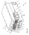
- FIG. 1C is a lateral cross-section isometric view schematically illustrating details of the resonator and power-supply units and yet more details of the cooling unit of FIG. 1 .
- FIG. 2 is a longitudinal cross-section isometric view schematically illustrating another preferred embodiment of CO 2 waveguide-laser apparatus in accordance with the present invention, similar to the embodiment of FIG. 1 , but wherein the fans are arranged to drive air through the cooling-unit fins from the ends of the cooling unit to the center.
- FIG. 3 is an isometric view schematically illustrating yet another preferred embodiment of CO 2 waveguide-laser apparatus in accordance with the present invention, similar to the embodiment of FIG. 2 , but wherein the fans are arranged to drive air through the cooling-unit fins from one end of the cooling unit to the other end.
- FIG. 1 schematically illustrate a preferred embodiment 20 of CO 2 waveguide-laser apparatus in accordance with the present invention.
- FIG. 1 depicts a complete laser.
- FIGS. 1A, 1B, and 1C depict details of the laser not visible in FIG. 1 .
- Laser 10 includes an elongated resonator unit 22 , and an elongated RF power-supply unit 24 for energizing the resonator unit.
- the resonator and power-supply units have about the same length and width and are aligned parallel to each other spaced apart by a cooling unit 26 including a plurality of fins 28 spaced apart and parallel to each other in the width-direction of the laser and extending longitudinally between the resonator and power-supply units.
- a plurality of fans 30 on opposite sides of the cooling unit is arranged to draw air into the cooling unit and drive the air through spaces 29 between fins 28 to exit the cooling at each end of thereof.
- Resonator unit 22 is a sealed off enclosure having end plates 32 which accommodate resonator mirrors 34 , only two of which are visible in the drawings.
- the resonator of unit 22 is preferably a folded resonator, with two mirrors terminating the resonator and others (not shown) for folding the resonator axis. It is pointed out here that only sufficient details of resonator unit of resonator unit 22 are described and depicted for understanding principles of the present invention. Details of CO 2 waveguide-lasers are well known in the art. A detailed description of folded-resonator CO 2 waveguide-lasers in several folding configurations is provided in U.S. Pat. No. 6,788,722, assigned to the assignee of the present invention, and the complete disclosure of which is hereby incorporated herein by reference.
- fins 28 have different lengths, being longest in the center and progressively shorter towards the edges.
- the fins are arranges to leave plenum spaces 31 (see FIG. 1A ) between fans 30 to receive the air-input from the fans.
- plenum spaces 31 Within plenum spaces 31 is a plurality of baffles or “mini fins” 27 spaced apart in the length and width directions of the cooling unit.
- baffles 27 In the absence of baffles 27 , the plenum spaces would not be cooled by the flowing air as efficiently as the spaces occupied by fins 28 .
- the collective length of baffles is selected to provide a reasonable compromise between increasing efficiency of cooling in the plenum spaces and obstructing air flow into the plenum spaces. Space is left between all fins and baffles to accommodate a sealed electrical feed through 36 for making electrical (RF) connection between power-supply unit 24 and resonator unit 22 .
- FIG. 1C schematically illustrates a preferred construction arrangement of inventive laser 20 .
- fins and baffles of cooling unit 26 ; an enclosure 45 , base 46 and walls 47 resonator unit 22 ; and a base 38 and walls 39 of power-supply unit 24 are formed from a single aluminum extrusion.
- a cover plate 40 and end plates 49 (only one visible in FIG. 1C ) complete an enclosure 43 for the power supply unit.
- End plates 32 complete sealed enclosure 45 for the resonator unit.
- Plenum spaces and baffles in cooling unit 26 depicted in FIGS. 1A and 1B are formed by machining into the sides of the extrusion.
- the term “base” applied to the resonator and power supply units indicates a component-mounting surface of the unit, and is independent of the physical orientation of the units
- a ceramic plate 48 Within enclosure 45 of the resonator unit is a ceramic plate 48 , in a surface of which waveguide channels 50 are machined. Plate 48 is sandwiched between base 46 of the resonator unit and an electrode plate 52 which is electrically connected to feedthrough 36 . The channeled side of ceramic plate 48 is in contact with base 46 . With RF power applied to electrode plate 52 , a gas discharge is created in channels 50 for energizing the laser-resonator.
- the discharge is generated only in channels 50 , as the arrangement provides that only in the channels is the electric field sufficient to strike and maintain a discharge. Elsewhere the enclosure merely provides a gas-reservoir. Heat is generated as a result of the discharge in channels 50 . Placing the channeled side of ceramic plate in 52 in contact with base 46 optimizes transmission of heat from the discharge to base 46 on a side thereof in contact with cooling unit 30 .
- power supply unit 24 in power supply unit 24 the actual power-supply is assembled on a printed circuit board 42 supported on base 38 of the power supply unit.
- An aperture 44 in base 38 provides for an electrical conductor (not shown) between the power-supply and electrical feed through 36 of resonator unit 22 .
- Heat is generated in the RF power supply from the electrical impedance of electrical components (not shown).
- the power-supply is placed on base 38 of the power-supply unit to optimize heat conduction between the power-supply and cooling unit 26 .
- a particular advantage of the about central placement of common cooling unit 26 between resonator unit 22 and power-supply 24 minimizes any tendency for longitudinal bowing of the laser 20 (with corresponding change of beam pointing) minimizing if not altogether eliminating differential expansion between the power-supply unit and the resonator unit. Any such tendency is further minimized by constructing all components with the same material, such as aluminum as discussed above. Further, the elongated fin construction of cooling unit 26 provides for a high degree of longitudinal stiffness, which, in itself, resists what minimal bowing tendency might exist due to residual differential expansion.
- the laser depicted in FIG. 1 and FIG. 1A is representative of a CO 2 waveguide laser having an output of 35 Watts (W) driven by an RF power-supply having an output power of 350 W.
- the laser has a length of about 30 centimeters (cm) and a width of about 9 cm.
- the fins have a height of about 25 millimeters (mm), a width of about 1.7 mm and are laterally spaced apart by 1.7 mm.
- thickness T 1 of base 38 of power supply unit 24 and thickness T 2 of resonator unit 22 are selected such that the inventive laser is thermo-mechanically neutral.
- the term “thermo-mechanically neutral” means that any tendency for longitudinal bowing of the inventive laser is minimized if not altogether eliminated. In the above example this condition is achieved when thickness T 1 is about 6 mm and thickness T 2 is about 12 mm. In general thickness T 1 will usually be less than thickness T 2 , reflecting a fact that more heat is generated by the power supply than is generated by the gas-discharge of the laser resonator.
- FIG. 2 is a longitudinal cross-section isometric view schematically illustrating another preferred embodiment of CO 2 waveguide-laser apparatus 20 A in accordance with the present invention.
- Laser 20 A is similar to laser 20 of FIG. 1 and FIGS. 1A-C , with an exception that fans 30 are arranged to drive air through the cooling-unit fins from the ends of the cooling unit to exit laterally at the center.
- FIG. 3 is an isometric view schematically illustrating yet another preferred embodiment 20 B of CO 2 waveguide-laser apparatus in accordance with the present invention.
- Laser 20 B is similar to laser 20 of FIG. 2 , but wherein fans 30 are arranged to drive air through the cooling-unit fins from one end of the cooling unit to the other end.
- This arrangement has an advantage that a machining operation is not required to form plenum spaces in cooling unit 26 . This, however, is at the expense of a longer longitudinal temperature gradient.
Landscapes
- Physics & Mathematics (AREA)
- Electromagnetism (AREA)
- Engineering & Computer Science (AREA)
- Plasma & Fusion (AREA)
- Optics & Photonics (AREA)
- Chemical & Material Sciences (AREA)
- Chemical Kinetics & Catalysis (AREA)
- Lasers (AREA)
Abstract
Description
Claims (17)
Priority Applications (6)
| Application Number | Priority Date | Filing Date | Title |
|---|---|---|---|
| US14/688,369 US9614342B2 (en) | 2015-04-16 | 2015-04-16 | Air-cooled carbon-dioxide laser |
| ES16715738T ES2895503T3 (en) | 2015-04-16 | 2016-03-30 | Air cooled carbon dioxide laser |
| EP16715738.7A EP3284148B1 (en) | 2015-04-16 | 2016-03-30 | Air-cooled carbon-dioxide laser |
| PCT/US2016/024948 WO2016167964A1 (en) | 2015-04-16 | 2016-03-30 | Air-cooled carbon-dioxide laser |
| CN202410907676.2A CN119134026A (en) | 2015-04-16 | 2016-03-30 | Air cooled carbon dioxide laser |
| CN201680022250.2A CN107851959B (en) | 2015-04-16 | 2016-03-30 | Air-cooled CO2 laser |
Applications Claiming Priority (1)
| Application Number | Priority Date | Filing Date | Title |
|---|---|---|---|
| US14/688,369 US9614342B2 (en) | 2015-04-16 | 2015-04-16 | Air-cooled carbon-dioxide laser |
Publications (2)
| Publication Number | Publication Date |
|---|---|
| US20160308325A1 US20160308325A1 (en) | 2016-10-20 |
| US9614342B2 true US9614342B2 (en) | 2017-04-04 |
Family
ID=55702153
Family Applications (1)
| Application Number | Title | Priority Date | Filing Date |
|---|---|---|---|
| US14/688,369 Active US9614342B2 (en) | 2015-04-16 | 2015-04-16 | Air-cooled carbon-dioxide laser |
Country Status (5)
| Country | Link |
|---|---|
| US (1) | US9614342B2 (en) |
| EP (1) | EP3284148B1 (en) |
| CN (2) | CN107851959B (en) |
| ES (1) | ES2895503T3 (en) |
| WO (1) | WO2016167964A1 (en) |
Cited By (3)
| Publication number | Priority date | Publication date | Assignee | Title |
|---|---|---|---|---|
| USD823306S1 (en) * | 2016-12-01 | 2018-07-17 | Riegl Laser Measurement Systems Gmbh | Laser scanner |
| US10644474B2 (en) | 2018-03-07 | 2020-05-05 | Coherent, Inc. | Conductively-cooled slab laser |
| EP3865950A1 (en) * | 2020-02-12 | 2021-08-18 | Bundesdruckerei GmbH | Hologram exposure machine for introducing a volume reflection hologram into a hologram film |
Citations (9)
| Publication number | Priority date | Publication date | Assignee | Title |
|---|---|---|---|---|
| US5894493A (en) * | 1995-10-17 | 1999-04-13 | Universal Laser Systems, Inc. | Free-space gas slab laser |
| US5901167A (en) | 1997-04-30 | 1999-05-04 | Universal Laser Systems, Inc. | Air cooled gas laser |
| US6788722B1 (en) | 2000-07-10 | 2004-09-07 | Coherent, Inc. | High power waveguide laser |
| US20040179570A1 (en) * | 2003-01-24 | 2004-09-16 | Peter Vitruk | RF excited gas laser |
| US20050123011A1 (en) | 2003-12-04 | 2005-06-09 | Yefim Sukhman | Method and apparatus for cooling a laser |
| US20090213885A1 (en) * | 2008-02-22 | 2009-08-27 | Demaria Anthony J | Diffusion-cooled co2 laser with flexible housing |
| US20120219028A1 (en) | 2011-02-24 | 2012-08-30 | Morrow Clifford E | Ceramic Slab, Free-Space and Waveguide Lasers |
| US20120281728A1 (en) | 2011-05-03 | 2012-11-08 | Coherent, Inc. | Waveguide co2 laser with mutiply folded resonator |
| US8731015B2 (en) | 2012-03-30 | 2014-05-20 | Coherent, Inc. | Compact CO2 slab-laser |
Family Cites Families (3)
| Publication number | Priority date | Publication date | Assignee | Title |
|---|---|---|---|---|
| CN2270989Y (en) * | 1996-05-31 | 1997-12-17 | 叶元璋 | Computer host chip cooling device |
| CN201984415U (en) * | 2010-12-21 | 2011-09-21 | 深圳市万景华科技有限公司 | Cross-flow radiator and video card with same |
| CN104869784B (en) * | 2014-02-20 | 2018-03-16 | 海能达通信股份有限公司 | A kind of heat abstractor and communication equipment |
-
2015
- 2015-04-16 US US14/688,369 patent/US9614342B2/en active Active
-
2016
- 2016-03-30 CN CN201680022250.2A patent/CN107851959B/en active Active
- 2016-03-30 WO PCT/US2016/024948 patent/WO2016167964A1/en not_active Ceased
- 2016-03-30 EP EP16715738.7A patent/EP3284148B1/en active Active
- 2016-03-30 CN CN202410907676.2A patent/CN119134026A/en active Pending
- 2016-03-30 ES ES16715738T patent/ES2895503T3/en active Active
Patent Citations (10)
| Publication number | Priority date | Publication date | Assignee | Title |
|---|---|---|---|---|
| US5894493A (en) * | 1995-10-17 | 1999-04-13 | Universal Laser Systems, Inc. | Free-space gas slab laser |
| US5901167A (en) | 1997-04-30 | 1999-05-04 | Universal Laser Systems, Inc. | Air cooled gas laser |
| US6788722B1 (en) | 2000-07-10 | 2004-09-07 | Coherent, Inc. | High power waveguide laser |
| US20040179570A1 (en) * | 2003-01-24 | 2004-09-16 | Peter Vitruk | RF excited gas laser |
| US20050123011A1 (en) | 2003-12-04 | 2005-06-09 | Yefim Sukhman | Method and apparatus for cooling a laser |
| US20090213885A1 (en) * | 2008-02-22 | 2009-08-27 | Demaria Anthony J | Diffusion-cooled co2 laser with flexible housing |
| US20120219028A1 (en) | 2011-02-24 | 2012-08-30 | Morrow Clifford E | Ceramic Slab, Free-Space and Waveguide Lasers |
| US8422528B2 (en) * | 2011-02-24 | 2013-04-16 | Iradion Laser, Inc. | Ceramic slab, free-space and waveguide lasers |
| US20120281728A1 (en) | 2011-05-03 | 2012-11-08 | Coherent, Inc. | Waveguide co2 laser with mutiply folded resonator |
| US8731015B2 (en) | 2012-03-30 | 2014-05-20 | Coherent, Inc. | Compact CO2 slab-laser |
Non-Patent Citations (1)
| Title |
|---|
| International Search Report and Written Opinion received for PCT Patent Application No. PCT/US2016/024948, mailed on Jun. 20, 2016, 13 pages. |
Cited By (4)
| Publication number | Priority date | Publication date | Assignee | Title |
|---|---|---|---|---|
| USD823306S1 (en) * | 2016-12-01 | 2018-07-17 | Riegl Laser Measurement Systems Gmbh | Laser scanner |
| US10644474B2 (en) | 2018-03-07 | 2020-05-05 | Coherent, Inc. | Conductively-cooled slab laser |
| US11336070B2 (en) | 2018-03-07 | 2022-05-17 | Coherent, Inc. | Conductively-cooled slab laser |
| EP3865950A1 (en) * | 2020-02-12 | 2021-08-18 | Bundesdruckerei GmbH | Hologram exposure machine for introducing a volume reflection hologram into a hologram film |
Also Published As
| Publication number | Publication date |
|---|---|
| CN107851959B (en) | 2024-07-30 |
| US20160308325A1 (en) | 2016-10-20 |
| CN119134026A (en) | 2024-12-13 |
| ES2895503T3 (en) | 2022-02-21 |
| WO2016167964A1 (en) | 2016-10-20 |
| CN107851959A (en) | 2018-03-27 |
| EP3284148A1 (en) | 2018-02-21 |
| EP3284148B1 (en) | 2021-10-20 |
Similar Documents
| Publication | Publication Date | Title |
|---|---|---|
| CN103518295B (en) | Ceramic slab, free space and waveguide lasers | |
| US20090213885A1 (en) | Diffusion-cooled co2 laser with flexible housing | |
| US4099143A (en) | Gas recirculating stabilized laser | |
| US5901167A (en) | Air cooled gas laser | |
| JP2001053360A (en) | Glass slab laser | |
| JP2008509556A (en) | Dielectric-coupled carbon dioxide slab laser | |
| US9614342B2 (en) | Air-cooled carbon-dioxide laser | |
| US7970038B2 (en) | Slab laser with stand-off for ceramic spacers | |
| US8611391B2 (en) | Waveguide CO2 laser with mutiply folded resonator | |
| JP2023033546A (en) | Conductive cooled slab laser | |
| EP3286810B1 (en) | Water-cooled carbon-dioxide laser | |
| EA024141B1 (en) | Laser device and method for generating laser light | |
| CN101849331A (en) | Laser having distributed inductances | |
| JPH06310789A (en) | Position regulator of spare ionization pin for excimer laser | |
| JP2003060269A (en) | Laser device | |
| JP2013187270A (en) | Laser oscillator | |
| JP2001053363A (en) | Gas laser oscillation device | |
| JPH01246881A (en) | Gas laser oscillating device |
Legal Events
| Date | Code | Title | Description |
|---|---|---|---|
| AS | Assignment |
Owner name: COHERENT, INC., CALIFORNIA Free format text: ASSIGNMENT OF ASSIGNORS INTEREST;ASSIGNORS:MUELLER, ERIC R.;PAPANIDE, ADRIAN;SIGNING DATES FROM 20150427 TO 20150428;REEL/FRAME:035540/0967 |
|
| AS | Assignment |
Owner name: BARCLAYS BANK PLC, AS COLLATERAL AGENT, NEW YORK Free format text: NOTICE OF GRANT OF SECURITY INTEREST IN PATENTS;ASSIGNOR:COHERENT, INC.;REEL/FRAME:040575/0001 Effective date: 20161107 |
|
| FEPP | Fee payment procedure |
Free format text: PAYER NUMBER DE-ASSIGNED (ORIGINAL EVENT CODE: RMPN); ENTITY STATUS OF PATENT OWNER: LARGE ENTITY Free format text: PAYOR NUMBER ASSIGNED (ORIGINAL EVENT CODE: ASPN); ENTITY STATUS OF PATENT OWNER: LARGE ENTITY |
|
| STCF | Information on status: patent grant |
Free format text: PATENTED CASE |
|
| MAFP | Maintenance fee payment |
Free format text: PAYMENT OF MAINTENANCE FEE, 4TH YEAR, LARGE ENTITY (ORIGINAL EVENT CODE: M1551); ENTITY STATUS OF PATENT OWNER: LARGE ENTITY Year of fee payment: 4 |
|
| AS | Assignment |
Owner name: JPMORGAN CHASE BANK, N.A., AS COLLATERAL AGENT, NEW YORK Free format text: SECURITY INTEREST;ASSIGNORS:II-VI INCORPORATED;II-VI DELAWARE, INC.;M CUBED TECHNOLOGIES, INC.;AND OTHERS;REEL/FRAME:060562/0254 Effective date: 20220701 Owner name: COHERENT, INC., CALIFORNIA Free format text: PATENT RELEASE AND REASSIGNMENT - RELEASE OF REEL/FRAME 040575/0001;ASSIGNOR:BARCLAYS BANK PLC, AS COLLATERAL AGENT;REEL/FRAME:060562/0650 Effective date: 20220701 |
|
| MAFP | Maintenance fee payment |
Free format text: PAYMENT OF MAINTENANCE FEE, 8TH YEAR, LARGE ENTITY (ORIGINAL EVENT CODE: M1552); ENTITY STATUS OF PATENT OWNER: LARGE ENTITY Year of fee payment: 8 |