EP3762149B1 - Spray tip design and manufacture - Google Patents
Spray tip design and manufacture Download PDFInfo
- Publication number
- EP3762149B1 EP3762149B1 EP19767505.1A EP19767505A EP3762149B1 EP 3762149 B1 EP3762149 B1 EP 3762149B1 EP 19767505 A EP19767505 A EP 19767505A EP 3762149 B1 EP3762149 B1 EP 3762149B1
- Authority
- EP
- European Patent Office
- Prior art keywords
- stem
- orifice
- insert
- channel
- orifice insert
- Prior art date
- Legal status (The legal status is an assumption and is not a legal conclusion. Google has not performed a legal analysis and makes no representation as to the accuracy of the status listed.)
- Active
Links
Images









Classifications
-
- B—PERFORMING OPERATIONS; TRANSPORTING
- B05—SPRAYING OR ATOMISING IN GENERAL; APPLYING FLUENT MATERIALS TO SURFACES, IN GENERAL
- B05B—SPRAYING APPARATUS; ATOMISING APPARATUS; NOZZLES
- B05B15/00—Details of spraying plant or spraying apparatus not otherwise provided for; Accessories
- B05B15/60—Arrangements for mounting, supporting or holding spraying apparatus
- B05B15/65—Mounting arrangements for fluid connection of the spraying apparatus or its outlets to flow conduits
-
- B—PERFORMING OPERATIONS; TRANSPORTING
- B05—SPRAYING OR ATOMISING IN GENERAL; APPLYING FLUENT MATERIALS TO SURFACES, IN GENERAL
- B05B—SPRAYING APPARATUS; ATOMISING APPARATUS; NOZZLES
- B05B1/00—Nozzles, spray heads or other outlets, with or without auxiliary devices such as valves, heating means
- B05B1/02—Nozzles, spray heads or other outlets, with or without auxiliary devices such as valves, heating means designed to produce a jet, spray, or other discharge of particular shape or nature, e.g. in single drops, or having an outlet of particular shape
-
- B—PERFORMING OPERATIONS; TRANSPORTING
- B05—SPRAYING OR ATOMISING IN GENERAL; APPLYING FLUENT MATERIALS TO SURFACES, IN GENERAL
- B05B—SPRAYING APPARATUS; ATOMISING APPARATUS; NOZZLES
- B05B9/00—Spraying apparatus for discharge of liquids or other fluent material, without essentially mixing with gas or vapour
- B05B9/01—Spray pistols, discharge devices
-
- B—PERFORMING OPERATIONS; TRANSPORTING
- B05—SPRAYING OR ATOMISING IN GENERAL; APPLYING FLUENT MATERIALS TO SURFACES, IN GENERAL
- B05B—SPRAYING APPARATUS; ATOMISING APPARATUS; NOZZLES
- B05B1/00—Nozzles, spray heads or other outlets, with or without auxiliary devices such as valves, heating means
- B05B1/02—Nozzles, spray heads or other outlets, with or without auxiliary devices such as valves, heating means designed to produce a jet, spray, or other discharge of particular shape or nature, e.g. in single drops, or having an outlet of particular shape
- B05B1/04—Nozzles, spray heads or other outlets, with or without auxiliary devices such as valves, heating means designed to produce a jet, spray, or other discharge of particular shape or nature, e.g. in single drops, or having an outlet of particular shape in flat form, e.g. fan-like, sheet-like
-
- B—PERFORMING OPERATIONS; TRANSPORTING
- B05—SPRAYING OR ATOMISING IN GENERAL; APPLYING FLUENT MATERIALS TO SURFACES, IN GENERAL
- B05B—SPRAYING APPARATUS; ATOMISING APPARATUS; NOZZLES
- B05B1/00—Nozzles, spray heads or other outlets, with or without auxiliary devices such as valves, heating means
- B05B1/34—Nozzles, spray heads or other outlets, with or without auxiliary devices such as valves, heating means designed to influence the nature of flow of the liquid or other fluent material, e.g. to produce swirl
-
- B—PERFORMING OPERATIONS; TRANSPORTING
- B05—SPRAYING OR ATOMISING IN GENERAL; APPLYING FLUENT MATERIALS TO SURFACES, IN GENERAL
- B05B—SPRAYING APPARATUS; ATOMISING APPARATUS; NOZZLES
- B05B13/00—Machines or plants for applying liquids or other fluent materials to surfaces of objects or other work by spraying, not covered by groups B05B1/00 - B05B11/00
- B05B13/02—Means for supporting work; Arrangement or mounting of spray heads; Adaptation or arrangement of means for feeding work
- B05B13/0278—Arrangement or mounting of spray heads
-
- B—PERFORMING OPERATIONS; TRANSPORTING
- B21—MECHANICAL METAL-WORKING WITHOUT ESSENTIALLY REMOVING MATERIAL; PUNCHING METAL
- B21K—MAKING FORGED OR PRESSED METAL PRODUCTS, e.g. HORSE-SHOES, RIVETS, BOLTS OR WHEELS
- B21K21/00—Making hollow articles not covered by a single preceding sub-group
- B21K21/08—Shaping hollow articles with different cross-section in longitudinal direction, e.g. nozzles, spark-plugs
-
- B—PERFORMING OPERATIONS; TRANSPORTING
- B23—MACHINE TOOLS; METAL-WORKING NOT OTHERWISE PROVIDED FOR
- B23K—SOLDERING OR UNSOLDERING; WELDING; CLADDING OR PLATING BY SOLDERING OR WELDING; CUTTING BY APPLYING HEAT LOCALLY, e.g. FLAME CUTTING; WORKING BY LASER BEAM
- B23K26/00—Working by laser beam, e.g. welding, cutting or boring
- B23K26/36—Removing material
- B23K26/38—Removing material by boring or cutting
- B23K26/382—Removing material by boring or cutting by boring
- B23K26/389—Removing material by boring or cutting by boring of fluid openings, e.g. nozzles, jets
-
- B—PERFORMING OPERATIONS; TRANSPORTING
- B23—MACHINE TOOLS; METAL-WORKING NOT OTHERWISE PROVIDED FOR
- B23P—METAL-WORKING NOT OTHERWISE PROVIDED FOR; COMBINED OPERATIONS; UNIVERSAL MACHINE TOOLS
- B23P13/00—Making metal objects by operations essentially involving machining but not covered by a single other subclass
- B23P13/02—Making metal objects by operations essentially involving machining but not covered by a single other subclass in which only the machining operations are important
-
- B—PERFORMING OPERATIONS; TRANSPORTING
- B05—SPRAYING OR ATOMISING IN GENERAL; APPLYING FLUENT MATERIALS TO SURFACES, IN GENERAL
- B05B—SPRAYING APPARATUS; ATOMISING APPARATUS; NOZZLES
- B05B1/00—Nozzles, spray heads or other outlets, with or without auxiliary devices such as valves, heating means
- B05B1/02—Nozzles, spray heads or other outlets, with or without auxiliary devices such as valves, heating means designed to produce a jet, spray, or other discharge of particular shape or nature, e.g. in single drops, or having an outlet of particular shape
- B05B1/04—Nozzles, spray heads or other outlets, with or without auxiliary devices such as valves, heating means designed to produce a jet, spray, or other discharge of particular shape or nature, e.g. in single drops, or having an outlet of particular shape in flat form, e.g. fan-like, sheet-like
- B05B1/048—Nozzles, spray heads or other outlets, with or without auxiliary devices such as valves, heating means designed to produce a jet, spray, or other discharge of particular shape or nature, e.g. in single drops, or having an outlet of particular shape in flat form, e.g. fan-like, sheet-like having a flow conduit with, immediately behind the outlet orifice, an elongated cross section, e.g. of oval or elliptic form, of which the major axis is perpendicular to the plane of the jet
-
- B—PERFORMING OPERATIONS; TRANSPORTING
- B05—SPRAYING OR ATOMISING IN GENERAL; APPLYING FLUENT MATERIALS TO SURFACES, IN GENERAL
- B05B—SPRAYING APPARATUS; ATOMISING APPARATUS; NOZZLES
- B05B15/00—Details of spraying plant or spraying apparatus not otherwise provided for; Accessories
- B05B15/50—Arrangements for cleaning; Arrangements for preventing deposits, drying-out or blockage; Arrangements for detecting improper discharge caused by the presence of foreign matter
- B05B15/52—Arrangements for cleaning; Arrangements for preventing deposits, drying-out or blockage; Arrangements for detecting improper discharge caused by the presence of foreign matter for removal of clogging particles
- B05B15/531—Arrangements for cleaning; Arrangements for preventing deposits, drying-out or blockage; Arrangements for detecting improper discharge caused by the presence of foreign matter for removal of clogging particles using backflow
- B05B15/534—Arrangements for cleaning; Arrangements for preventing deposits, drying-out or blockage; Arrangements for detecting improper discharge caused by the presence of foreign matter for removal of clogging particles using backflow by reversing the nozzle relative to the supply conduit
-
- Y—GENERAL TAGGING OF NEW TECHNOLOGICAL DEVELOPMENTS; GENERAL TAGGING OF CROSS-SECTIONAL TECHNOLOGIES SPANNING OVER SEVERAL SECTIONS OF THE IPC; TECHNICAL SUBJECTS COVERED BY FORMER USPC CROSS-REFERENCE ART COLLECTIONS [XRACs] AND DIGESTS
- Y10—TECHNICAL SUBJECTS COVERED BY FORMER USPC
- Y10T—TECHNICAL SUBJECTS COVERED BY FORMER US CLASSIFICATION
- Y10T29/00—Metal working
- Y10T29/49—Method of mechanical manufacture
- Y10T29/49316—Impeller making
- Y10T29/4932—Turbomachine making
- Y10T29/49323—Assembling fluid flow directing devices, e.g., stators, diaphragms, nozzles
-
- Y—GENERAL TAGGING OF NEW TECHNOLOGICAL DEVELOPMENTS; GENERAL TAGGING OF CROSS-SECTIONAL TECHNOLOGIES SPANNING OVER SEVERAL SECTIONS OF THE IPC; TECHNICAL SUBJECTS COVERED BY FORMER USPC CROSS-REFERENCE ART COLLECTIONS [XRACs] AND DIGESTS
- Y10—TECHNICAL SUBJECTS COVERED BY FORMER USPC
- Y10T—TECHNICAL SUBJECTS COVERED BY FORMER US CLASSIFICATION
- Y10T29/00—Metal working
- Y10T29/49—Method of mechanical manufacture
- Y10T29/49428—Gas and water specific plumbing component making
- Y10T29/49432—Nozzle making
Definitions
- Spray tips are typically used in a variety of applications to break up, or atomize, a liquid material for delivery in a desired spray pattern.
- Some exemplary applications include, but are not limited to, applying a coating material such as paint, to a substrate, an agricultural application such as applying a fertilizer, insecticide, or herbicide to plants.
- paint includes substances composed of coloring matter, or pigments, suspended in a liquid medium as well as substances that are free of coloring matter or pigment. Paint may also include preparatory coatings, such as primers, and can be opaque, transparent, or semi-transparent. Some particular examples include, but are not limited to, latex paint, oil-based paint, stain, lacquers, varnishes, inks, etc.
- An improved reversible spray tip for use with airless paint spraying equipment to project a spray pattern, and mountable on a pressurized paint sprayer comprising: a nozzle carrier, rotatable about an axis, and having a fluid passage and a spray nozzle in said fluid passage; a cam which co-rotates with said rotatable nozzle carrier, said cam having a position stop; and a counterstop disposed to engage said position stop when said nozzle carrier is rotated to a predetermined rotational position, so that rotation of said nozzle carrier from said given rotational position is bidirectionally resisted; wherein said position stop comprises a projecting detent for resisting rotation of said rotatable nozzle carrier.
- a spray device comprising: a rotatable, reversible spray tip, the spray tip having a handle for rotating the spray tip relative to a body of the spray device; a safety lock operatively connected to a) the body of spray device, b) a safety guard of the spray device, or c) a portion of a spray tip assembly of the spray device, the safety lock having a cover substantially conforming to the shape of the handle such that the cover is selectively engageable with the handle to prevent the handle from rotating out of a spraying position.
- a spray nozzle comprising: a nozzle body, a nozzle entry orifice through which a material to be sprayed can enter, a nozzle bore through which a material to be sprayed can pass, a nozzle exit orifice through which a material to be sprayed can exit, a diamond bore liner in said bore for providing low wear, durable and long-lasting service in the nozzle.
- An airless spray gun nozzle comprising: a cylindrical nozzle seat, wherein the end portion of the cylindrical nozzle seat forms a cross-shaped four passages, wherein two adjacent nozzles are respectively embedded with a circular nozzle and An elliptical nozzle such that the circular nozzle and the elliptical nozzle are at a 90° cross-distribution;
- the nozzle holder is connected to the nozzle guard through the left and right snap rings;
- the left and right snap rings are composed of two semi-circular snap rings, one end of the two semi-circular snap rings is fastened by a buckle, and the other end is fastened by a snap ring cap;
- a semi-circular track groove is formed on the inner side of the curved portion of the shape snap ring; the semi-circular track groove can provide a guide for the rotation of the nozzle seat;
- the nozzle holder is provided with two bumps, and the two bumps correspond to
- Document GB 2 085 759 A which discloses the following, is also known from the prior art: A method of manufacturing a spray nozzle comprising a nozzle tip and nozzle adapter, the nozzle tip being made from a hard, abrasive resistant material and the nozzle adapter being made from a material which is less hard, less abrasive resistant, and more easily machineable than the material from which the nozzle tip is made, the method comprising the steps of forming a generally semi-spherical dome shaped external peripheral surface on the tip, forming an axial approach passage in the tip terminating in a blind, generally semi-spherical end cavity coaxially aligned with the approach passage and the dome shaped peripheral surface, drilling and counterboring an axial passage through the adapter, the counterbored portion of the axial passage extending inwardly from a front face of the adapter; machining an annular groove in the frontface of the adapter so as to form an annular lip on said front face between the counterbored passage and the annul
- a spray tip for a fluid applicator includes a stem configured to be inserted into the fluid applicator.
- the stem includes a stem pre-orifice portion and an insert receiving portion.
- the spray tip includes a pre-orifice insert having an inlet and an outlet.
- the pre-orifice insert is disposed within the insert receiving portion and disposed against a rearward shoulder of the stem.
- a pump receives and pressurizes a fluid, delivers the pressurized fluid to an applicator, which, in turn, applies the pressurized fluid to a surface using a spray tip having a geometry selected to emit a desired spray pattern (e.g., a round pattern, a flat pattern, or a fan pattern, etc.).
- the fluid may comprise any fluid applied to surfaces, including, but not limited to, for example, paint, primer, lacquers, foams, textured materials, plural components, adhesive components, etc.
- paint, primer, lacquers foams, textured materials, plural components, adhesive components, etc.
- FIG. 1 is a side view showing an example applicator 10.
- Applicator 10 is used in a fluid spraying system to apply fluid to a surface (e.g., apply paint to a wall). The fluid enters through inlet 20, and exits from outlet 50, after passing through a fluid channel (not explicitly shown) within applicator 10.
- Tip 30 is coupled to applicator 10 and has an outlet 50. Tip 30 often is reversible or removable from applicator 10.
- Tip 30 may have a pre-orifice configuration consisting of an internal geometry that provides a desired spray pattern (e.g., a fan that has minimal tailings or other beneficial fluid dynamics).
- Fig. 2A is a side view showing an example spray tip 100.
- Spray tip 100 for example, could be used in applicator 10.
- Spray tip 100 includes stem 102, flag 103 and channel 104.
- Stem 102 is typically cylindrical to allow rotation of spray tip 100 in an applicator (e.g., applicator 10 in FIG. 1 ).
- Stem 102 can be formed of stainless steel, tungsten carbide or another suitable material.
- Flag 103 couples to stem 102 and allows a user to rotate and remove spray tip 100 from applicator 10.
- Flag 103 can be press fit over stem or over molded onto stem, but other materials and methods of attachment are also envisioned.
- Channel 104 is disposed through stem 102 and allows fluid flow through spray tip 100.
- Channel 104 and components disposed within channel 104 can be shaped to accommodate different fluids and spray patterns.
- FIG. 2B is a sectional view of spray tip 100 along section A-A in FIG. 2A .
- stem 102 includes a channel 104 that allows fluid flow through stem 102.
- channel 104 Within channel 104 are pre-orifice inserts 106 and 108. Fluid flows in through channel 104 into pre-orifice insert 108 and then into pre-orifice insert 106 before being expelled through orifice 107.
- the internal structure of channel 104, pre-orifice insert 108, and pre-orifice insert 106 can greatly affect the spray pattern expelled from orifice 107.
- Spray tip 100 may be manufactured using current assembly processes for spray tips. Normally, pre-orifice inserts 106 and 108 are manufactured separately from stem 102, and then inserted into channel 104. Such machining often utilizes outside diameter (OD) grinding of pre-orifice inserts 106 and 108 (which generally comprise tungsten carbide) with tight press tolerances. The pre-orifice inserts 106 and 108 are then inserted into channel 104 of stem 102. This process can create a large amount of scrap. Additionally, after the OD grinding process, pre-orifice inserts 106 and 108 might not press into stem 102 straight - in which case the assembly is considered a failure (e.g., the inserts do not align properly and can affect a desired spray pattern).
- OD outside diameter
- the filler metal used is a silver brazing filler metal.
- suitable brazing filler metals, and other suitable bonding agents are also envisioned.
- Fig. 3A is a flow diagram showing an example assembly operation 250.
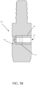
- Assembly operation 250 is generally known, however, the internal geometries shown in FIGS. 3B and 3C , respectively show low-pressure and high-pressure geometry configurations.
- Assembly operation 250 begins at block 252 where a stem is provided for example stem 200 shown in FIGS. 3B and 3C .
- Channel 202 is formed through stem 200.
- Channel 202 can be formed in a variety of different ways as indicated by blocks 256-260.
- channel 202 can be machined or drilled through stem 200.
- stem 200 is first formed as a cylinder and channel 202 is then bored into the cylindrical body of stem 200.
- channel 202 can be casted or molded at the same time as stem 200.
- the cylindrical shape of stem 200 is formed by a casting process, however, a die is placed in the casting mold to create channel 202 in the stem forming casting process.
- channel 202 can be formed in other ways as well.
- Assembly operation 250 proceeds at block 262 where pre-orifice inserts 204 are inserted within the stem 200. Assembly operation 250 then proceeds to block 264 where the pre-orifice inserts 204 are secured within stem 200. For example, the inserts are press fit against block 206 and as fluid flows through the inserts they are further forced against block 206 and cannot be pushed through entirely through channel 202. In one example, pre-orifice inserts 204 are press fit into channel 202 and are held in by friction.
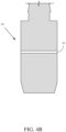
- Fig. 4A is a flow diagram showing an example assembly operation 340. Assembly operation 340 will be described with reference to FIGS. 4B-4F . Assembly operation 340 begins at block 350 where a stem is provided (e.g., stem 300).
- a stem is provided (e.g., stem 300).
- Assembly operation 340 proceeds at block 360 where a channel 302 is formed through the stem 300.
- Channel 302 is shown formed in FIG. 4B .
- Channel 302 can be formed in a variety of different ways as indicated by blocks 362-366.
- channel 302 can be machined or drilled through stem 300.
- a drill bit, end mill, or other tooling can be used to subtractively create the channel 302.
- the channel 302 can be cast or molded into stem 300 during casting or molding of stem 300.
- a die is provided through the body of the mold to create channel 302.
- channel 302 can be formed in stem 300 in other ways as well.
- Assembly operation 340 proceeds at block 370 where internal geometry is formed in the stem.
- internal geometry can include channel 302.
- portion 304-1 includes a cylindrical geometric portion
- portion 304-2 is a frustoconical geometric portion
- portion 304-3 is a cylindrical portion with a smaller diameter of than portion 304-1.
- portion 304-3 is the unmodified portion of channel 302 shown in FIG. 4B .
- the internal geometry formed in stem 300 can be formed in a variety of different ways as indicated by blocks 372-376. As indicated by block 372, the internal geometry can be machined or drilled in stem 300.
- portion(s) 304 can be formed while casting or molding stem 300. Portion(s) 304 can be formed in other ways as well, as indicated by block 376.
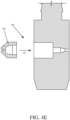
- Assembly operation 340 proceeds at block 380 where a pre-orifice retaining portion is formed (as shown in FIG. 4D ) and the pre-orifice insert is inserted within stem 300 (as shown in FIG. 4E ).
- pre-orifice insert receiving portion 306 can be formed in similar ways as portions 304 (e.g., drilled, milled, molded, etc.). After the pre-orifice insert receiving portion 306 is formed, pre-orifice insert 308 can be inserted into pre-orifice insert receiving portion 306. In some examples, pre-orifice insert 308 is press fit into pre-orifice insert receiving portion 306.
- pre-orifice insert 308 snugly fits into pre-orifice insert receiving portion 306 such that a press is not needed. In other examples, pre-orifice insert 308 can loosely fit in pre-orifice insert receiving portion 306 to allow for more aligning options. In some examples, more than one pre-orifice insert 308 can be inserted into pre-orifice insert receiving portion 306.
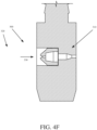
- Assembly operation 340 proceeds at block 390 where the pre-orifice insert is secured within the stem.
- Pre-orifice insert 308 can be secured within the stem in a variety of different ways as indicated by block 392-398.
- the pre-orifice insert 308 can be secured by brazing pre-orifice insert 308 into stem 300.
- a filler metal can be provided and brazed from the downstream direction of pre-orifice insert 308 and fill in a gap between pre-orifice insert 308 and stem 300, securing pre-orifice insert 308.
- a bonding agent can be used to secure pre-orifice insert 308 in stem 300.
- pre-orifice insert 308 can be used as a bonding agent to secure pre-orifice insert 308 into stem 300.
- pre-orifice insert 308 can be secured in stem 300 by friction of (e.g., pre-orifice insert 308 tightly fits in pre-orifice insert receiving portion 306 such that it will not fall out under an applied fluid pressure flowing through channel 302).
- Pre-orifice insert 308 can be secured in other ways as well, as indicated by block 398.
- a combination of one or more methods could be used.
- pre-orifice insert 308 may be secured using friction and a bonding agent.
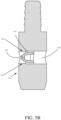
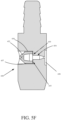
- FIGS. 5A-5F are sectional views showing example spray tip assembly configurations.
- a stem 400 includes a stem pre-orifice portion 404, configured to guide fluid to pre-orifice insert 402. Gap 406 between pre-orifice insert 402 and stem 400, can allow for a fastening material to be applied to couple pre-orifice insert 402 to stem 400.
- a fastening material may include filler or a bonding agent (e.g., a silver brazing filler metal, an epoxy or a different bonding agent).
- pre-orifice insert 402 is disposed rearwardly against rear shoulder 405 such that fluid does not flow around pre-orifice insert 402. In some examples, the fastening material couples and/or bonds pre-orifice insert 402 to rear shoulder 405.
- stem 410 includes a stem pre-orifice portion 414, configured to guide fluid to a pre-orifice insert 412. Gap 416 between pre-orifice insert 412 and stem 410 can allow for a fastening material to be applied to couple pre-orifice insert 412 within stem 410.
- a fastening material may include filler metal or a bonding agent (e.g., a silver brazing filler metal, an epoxy or some other bonding agent).
- pre-orifice insert 402 is disposed rearwardly of forward shoulder 415. In some examples, the fastening material couples and/or bonds pre-orifice insert 402 to forward shoulder 415.
- stem 420 includes a stem pre-orifice portion 424, configured to guide fluid to a pre-orifice insert 422. Gap 426 between pre-orifice insert 422 and stem 420 can allow for a fastening material to be applied to couple pre-orifice insert 422 within stem 420.
- a fastening material may include brazing material or a bonding agent (e.g., a silver brazing material or an epoxy bonding agent).
- pre-orifice insert 422 is disposed forwardly against forward shoulder 425 such that fluid under pressure does not force pre-orifice insert 422 out of stem 420. In some examples, the fastening material couples and/or bonds pre-orifice insert 422 to forward shoulder 425.
- stem 430 comprises a stem pre-orifice portion 434, configured to guide fluid to a pre-orifice insert 432.
- Stem pre-orifice portion 434 may be machined or drilled as described above.
- Gap 436 between pre-orifice insert 432 and stem 430 can allow for a fastening material to be applied to couple pre-orifice insert 432 within stem 430.
- a fastening material may include brazing material or a bonding agent (e.g., a silver brazing material or an epoxy bonding agent).
- stem 440 includes a stem pre-orifice portion 444, configured to guide fluid to a pre-orifice insert 442.
- Stem pre-orifice portion 444 includes a cylinder 441, a frustrum 443 and a cylinder 445.
- stem pre-orifice portion 444 can include other internal geometry in different configurations.
- stem pre-orifice portion 444 can include the geometry of any available pre-orifice insert.
- stem pre-orifice portion 444 can remove the need for having two pre-orifice inserts to create internal concave geometry, such as a cavity or chamber that is wider than either the inlet or outlet.
- Gap 446 between pre-orifice insert 442 and stem 440 can allow for a fastening material to be applied to couple pre-orifice insert 442 within stem 440.
- a fastening material may include brazing material or a bonding agent (e.g., a silver brazing material or an epoxy bonding agent).
- Gap 446 can be determined based on the properties of the brazing material or bonding agent. In one example, gap 446 includes a distance in the range 0.000 mm - 0.635 mm (0.000 inches - 0.025 inches). In one example, gap 446 includes a distance in the range 0.0254 mm - 0.127 mm (0.001 inches - 0.005 inches).
- pre-orifice insert 442 is disposed rearwardly against rear shoulder 447 such that fluid does not flow around pre-orifice insert 442 and/or in between pre-orifice insert 442 and stem 440.
- the fastening material couples and/or bonds pre-orifice insert 442 to rear shoulder 447.
- stem 450 includes a stem pre-orifice portion 454, configured to guide fluid to a pre-orifice insert 452.
- Gap 456 between pre-orifice insert 452 and stem 450 can allow for a fastening material 457 to be applied to couple pre-orifice insert 442 within stem 440.
- Fastening material 457 may include brazing material or a bonding agent (e.g., a silver brazing material or an epoxy bonding agent).
- Stem 450 includes a counter bore 458.
- Counter bore 458, as shown, includes a cylindrical shape. However, in other examples, counter bore 458 can include other geometries (e.g., frustums, steps, spheres, etc.).
- pre-orifice insert 452 is disposed rearwardly against rear shoulder 455 such that fluid does not flow around pre-orifice insert 452.
- the fastening material 457 couples and/or bonds pre-orifice insert 452 to rear shoulder 455.
Landscapes
- Engineering & Computer Science (AREA)
- Mechanical Engineering (AREA)
- Physics & Mathematics (AREA)
- Optics & Photonics (AREA)
- Plasma & Fusion (AREA)
- Nozzles (AREA)
Description
- Spray tips are typically used in a variety of applications to break up, or atomize, a liquid material for delivery in a desired spray pattern. Some exemplary applications include, but are not limited to, applying a coating material such as paint, to a substrate, an agricultural application such as applying a fertilizer, insecticide, or herbicide to plants.
- While examples described herein are in the context of applying paint to a surface, it is understood that the concepts are not limited to these particular applications. As used herein, paint includes substances composed of coloring matter, or pigments, suspended in a liquid medium as well as substances that are free of coloring matter or pigment. Paint may also include preparatory coatings, such as primers, and can be opaque, transparent, or semi-transparent. Some particular examples include, but are not limited to, latex paint, oil-based paint, stain, lacquers, varnishes, inks, etc.
- Document
US 6 264 115 B1 , which discloses the following, is known from the prior art: An improved reversible spray tip for use with airless paint spraying equipment to project a spray pattern, and mountable on a pressurized paint sprayer, comprising: a nozzle carrier, rotatable about an axis, and having a fluid passage and a spray nozzle in said fluid passage; a cam which co-rotates with said rotatable nozzle carrier, said cam having a position stop; and a counterstop disposed to engage said position stop when said nozzle carrier is rotated to a predetermined rotational position, so that rotation of said nozzle carrier from said given rotational position is bidirectionally resisted; wherein said position stop comprises a projecting detent for resisting rotation of said rotatable nozzle carrier. - Document
US 2012/223155 A1 , which discloses the following, is also known from the prior art: A spray device, comprising: a rotatable, reversible spray tip, the spray tip having a handle for rotating the spray tip relative to a body of the spray device; a safety lock operatively connected to a) the body of spray device, b) a safety guard of the spray device, or c) a portion of a spray tip assembly of the spray device, the safety lock having a cover substantially conforming to the shape of the handle such that the cover is selectively engageable with the handle to prevent the handle from rotating out of a spraying position. - Document
US 2003/189114 A1 , which discloses the following, is also known from the prior art: A spray nozzle comprising: a nozzle body, a nozzle entry orifice through which a material to be sprayed can enter, a nozzle bore through which a material to be sprayed can pass, a nozzle exit orifice through which a material to be sprayed can exit, a diamond bore liner in said bore for providing low wear, durable and long-lasting service in the nozzle. - Document
US 3 556 411 A , which discloses the following, is also known from the prior art: In a liquid spray nozzle having flow capacity of not more than about 20 gallons of water per hour at 500 p.s.i., comprising a body having a central void, comprising at least in part an approach passage, with a longitudinal axis and a fan spray outlet orifice at one end of said passage and with a side inlet at the other end of said passage and with an imperforate sidewall from said one end to said inlet, the area of said inlet being harmoniously related to the effective area of said outlet in respect to turbulent flow therebetween, the improvement comprising means for preventing the longitudinal inflow of liquid to the inlet end of said passage and defining a turbulence chamber in said void adjacent said inlet, and liquid inlet conducting means for introducing liquid into said chamber transversely of said axis with velocity and direction tending to induce turbulence in said chamber and avoid substantial bodily rotation of the fluid stream in said passage about said axis adjacent said orifice; both said means and said passage coacting to create a turbulent stream in said passage with substantially uniform mean velocity across the whole. -
Document CN 104 148 198 A , which discloses the following, is also known from the prior art: An airless spray gun nozzle, comprising: a cylindrical nozzle seat, wherein the end portion of the cylindrical nozzle seat forms a cross-shaped four passages, wherein two adjacent nozzles are respectively embedded with a circular nozzle and An elliptical nozzle such that the circular nozzle and the elliptical nozzle are at a 90° cross-distribution; The nozzle holder is connected to the nozzle guard through the left and right snap rings; the left and right snap rings are composed of two semi-circular snap rings, one end of the two semi-circular snap rings is fastened by a buckle, and the other end is fastened by a snap ring cap; a semi-circular track groove is formed on the inner side of the curved portion of the shape snap ring; the semi-circular track groove can provide a guide for the rotation of the nozzle seat; The nozzle holder is provided with two bumps, and the two bumps correspond to the opening of the semi-circular rail groove and are inserted into the nozzle guard. - Document
GB 2 085 759 A - A spray tip for a fluid applicator includes a stem configured to be inserted into the fluid applicator. The stem includes a stem pre-orifice portion and an insert receiving portion. The spray tip includes a pre-orifice insert having an inlet and an outlet. The pre-orifice insert is disposed within the insert receiving portion and disposed against a rearward shoulder of the stem.
- This summary is provided to introduce a selection of concepts in a simplified form that are further described below in the Detailed Description. This summary is not intended to identify key features or essential features of the claimed subject matter, is not intended to describe each disclosed embodiment or every implementation of the claimed subject matter, and is not intended to be used as an aid in determining the scope of the claimed subject matter. Many other novel advantages, features, and relationships will become apparent as this description proceeds. The figures and the description that follow more particularly exemplify illustrative embodiments.
-
-
FIG. 1 is a side view of an example fluid applicator. -
FIGS. 2A is a side view showing an example spray tip. -
FIGS. 2B is a sectional view showing the example spray tip ofFIG. 2A . -
FIG. 3A is a flow diagram showing an example assembly operation of a spray tip. -
FIGS. 3B-3C are sectional views showing example steps of the assembly operation ofFIG. 3A . -
FIGS. 4A is a flow diagram showing an example assembly operation of a spray tip. -
FIGS. 4B-E are sectional views showing example steps of the assembly operation ofFIG. 4A . -
FIGS. 5A-5F are sectional views showing example spray tip assembly configurations. - In a fluid spraying system, a pump receives and pressurizes a fluid, delivers the pressurized fluid to an applicator, which, in turn, applies the pressurized fluid to a surface using a spray tip having a geometry selected to emit a desired spray pattern (e.g., a round pattern, a flat pattern, or a fan pattern, etc.). The fluid may comprise any fluid applied to surfaces, including, but not limited to, for example, paint, primer, lacquers, foams, textured materials, plural components, adhesive components, etc. For the sake of illustration, and not by limitation, the example of a paint spraying system will be described in detail.
-
FIG. 1 is a side view showing anexample applicator 10.Applicator 10 is used in a fluid spraying system to apply fluid to a surface (e.g., apply paint to a wall). The fluid enters throughinlet 20, and exits fromoutlet 50, after passing through a fluid channel (not explicitly shown) withinapplicator 10.Tip 30 is coupled toapplicator 10 and has anoutlet 50.Tip 30 often is reversible or removable fromapplicator 10.Tip 30 may have a pre-orifice configuration consisting of an internal geometry that provides a desired spray pattern (e.g., a fan that has minimal tailings or other beneficial fluid dynamics). -
Fig. 2A is a side view showing anexample spray tip 100.Spray tip 100, for example, could be used inapplicator 10.Spray tip 100 includesstem 102,flag 103 andchannel 104.Stem 102 is typically cylindrical to allow rotation ofspray tip 100 in an applicator (e.g.,applicator 10 inFIG. 1 ).Stem 102 can be formed of stainless steel, tungsten carbide or another suitable material.Flag 103 couples to stem 102 and allows a user to rotate and removespray tip 100 fromapplicator 10.Flag 103 can be press fit over stem or over molded onto stem, but other materials and methods of attachment are also envisioned. Channel 104 is disposed throughstem 102 and allows fluid flow throughspray tip 100. Channel 104 and components disposed withinchannel 104 can be shaped to accommodate different fluids and spray patterns. -
FIG. 2B is a sectional view ofspray tip 100 along section A-A inFIG. 2A . As shown,stem 102 includes achannel 104 that allows fluid flow throughstem 102. Withinchannel 104 arepre-orifice inserts channel 104 intopre-orifice insert 108 and then intopre-orifice insert 106 before being expelled throughorifice 107. The internal structure ofchannel 104,pre-orifice insert 108, andpre-orifice insert 106 can greatly affect the spray pattern expelled fromorifice 107. -
Spray tip 100 may be manufactured using current assembly processes for spray tips. Normally, pre-orifice inserts 106 and 108 are manufactured separately fromstem 102, and then inserted intochannel 104. Such machining often utilizes outside diameter (OD) grinding ofpre-orifice inserts 106 and 108 (which generally comprise tungsten carbide) with tight press tolerances. The pre-orifice inserts 106 and 108 are then inserted intochannel 104 ofstem 102. This process can create a large amount of scrap. Additionally, after the OD grinding process,pre-orifice inserts stem 102 straight - in which case the assembly is considered a failure (e.g., the inserts do not align properly and can affect a desired spray pattern). - It is desired for a spray tip assembly process that does not require an OD grind, and where the parts assembly utilizes a slip fit, with a filler metal in a brazing process used to fill any gap. In one example, the filler metal used is a silver brazing filler metal. However, other suitable brazing filler metals, and other suitable bonding agents, are also envisioned.
-
Fig. 3A is a flow diagram showing anexample assembly operation 250.Assembly operation 250 is generally known, however, the internal geometries shown inFIGS. 3B and3C , respectively show low-pressure and high-pressure geometry configurations.Assembly operation 250 begins atblock 252 where a stem is provided forexample stem 200 shown inFIGS. 3B and3C . -
Assembly operation 250 proceeds atblock 254 wherechannel 202 is formed throughstem 200.Channel 202 can be formed in a variety of different ways as indicated by blocks 256-260. As indicated byblock 256,channel 202 can be machined or drilled throughstem 200. For example, stem 200 is first formed as a cylinder andchannel 202 is then bored into the cylindrical body ofstem 200. As indicated byblock 258,channel 202 can be casted or molded at the same time asstem 200. For example, the cylindrical shape ofstem 200 is formed by a casting process, however, a die is placed in the casting mold to createchannel 202 in the stem forming casting process. As indicated byblock 260,channel 202 can be formed in other ways as well. -
Assembly operation 250 proceeds atblock 262 where pre-orifice inserts 204 are inserted within thestem 200.Assembly operation 250 then proceeds to block 264 where the pre-orifice inserts 204 are secured withinstem 200. For example, the inserts are press fit againstblock 206 and as fluid flows through the inserts they are further forced againstblock 206 and cannot be pushed through entirely throughchannel 202. In one example,pre-orifice inserts 204 are press fit intochannel 202 and are held in by friction. -
Fig. 4A is a flow diagram showing anexample assembly operation 340.Assembly operation 340 will be described with reference toFIGS. 4B-4F .Assembly operation 340 begins atblock 350 where a stem is provided (e.g., stem 300). -
Assembly operation 340 proceeds atblock 360 where achannel 302 is formed through thestem 300.Channel 302 is shown formed inFIG. 4B .Channel 302 can be formed in a variety of different ways as indicated by blocks 362-366. As indicated byblock 362,channel 302 can be machined or drilled throughstem 300. For example, a drill bit, end mill, or other tooling can be used to subtractively create thechannel 302. As indicated byblock 364, thechannel 302 can be cast or molded intostem 300 during casting or molding ofstem 300. For example, a die is provided through the body of the mold to createchannel 302. As indicate byblock 366,channel 302 can be formed instem 300 in other ways as well. -
Assembly operation 340 proceeds atblock 370 where internal geometry is formed in the stem. As shown inFIG. 4C , internal geometry can includechannel 302. As shown, portion 304-1 includes a cylindrical geometric portion, portion 304-2 is a frustoconical geometric portion and portion 304-3 is a cylindrical portion with a smaller diameter of than portion 304-1. In this instance, portion 304-3 is the unmodified portion ofchannel 302 shown inFIG. 4B . Of course these are only examples and more complex geometry can also be formed instem 300 such as step steps, spherical or other more complex shaping. The internal geometry formed instem 300 can be formed in a variety of different ways as indicated by blocks 372-376. As indicated byblock 372, the internal geometry can be machined or drilled instem 300. For example, utilizing thechannel 302 as a guide, a tapered bit could drill intochannel 302 all the way down to portion 304 - 3 and then to form portion 304-1 and 304-2. (Drilling with this tapered bit all the way throughstem 300 would create only one portion that would be similar to portion 304-1.). As indicated byblock 374, portion(s) 304 can be formed while casting ormolding stem 300. Portion(s) 304 can be formed in other ways as well, as indicated byblock 376. -
Assembly operation 340 proceeds atblock 380 where a pre-orifice retaining portion is formed (as shown inFIG. 4D ) and the pre-orifice insert is inserted within stem 300 (as shown inFIG. 4E ). For example, pre-orificeinsert receiving portion 306 can be formed in similar ways as portions 304 (e.g., drilled, milled, molded, etc.). After the pre-orificeinsert receiving portion 306 is formed,pre-orifice insert 308 can be inserted into pre-orificeinsert receiving portion 306. In some examples,pre-orifice insert 308 is press fit into pre-orificeinsert receiving portion 306. In other examples pre-orifice insert 308 snugly fits into pre-orificeinsert receiving portion 306 such that a press is not needed. In other examples,pre-orifice insert 308 can loosely fit in pre-orificeinsert receiving portion 306 to allow for more aligning options. In some examples, more than onepre-orifice insert 308 can be inserted into pre-orificeinsert receiving portion 306. -
Assembly operation 340 proceeds atblock 390 where the pre-orifice insert is secured within the stem.Pre-orifice insert 308 can be secured within the stem in a variety of different ways as indicated by block 392-398. As indicated byblock 392, thepre-orifice insert 308 can be secured by brazingpre-orifice insert 308 intostem 300. For example, a filler metal can be provided and brazed from the downstream direction ofpre-orifice insert 308 and fill in a gap betweenpre-orifice insert 308 and stem 300, securingpre-orifice insert 308. As indicated byblock 394, a bonding agent can be used to securepre-orifice insert 308 instem 300. For example, a glue, epoxy etc. can be used as a bonding agent to securepre-orifice insert 308 intostem 300. As indicated byblock 396,pre-orifice insert 308 can be secured instem 300 by friction of (e.g.,pre-orifice insert 308 tightly fits in pre-orificeinsert receiving portion 306 such that it will not fall out under an applied fluid pressure flowing through channel 302).Pre-orifice insert 308 can be secured in other ways as well, as indicated byblock 398. For example, a combination of one or more methods could be used. For instance,pre-orifice insert 308 may be secured using friction and a bonding agent. -
FIGS. 5A-5F are sectional views showing example spray tip assembly configurations. As shown inFIG. 5A , astem 400 includes astem pre-orifice portion 404, configured to guide fluid topre-orifice insert 402.Gap 406 betweenpre-orifice insert 402 and stem 400, can allow for a fastening material to be applied to couplepre-orifice insert 402 to stem 400. A fastening material may include filler or a bonding agent (e.g., a silver brazing filler metal, an epoxy or a different bonding agent). As shown,pre-orifice insert 402 is disposed rearwardly againstrear shoulder 405 such that fluid does not flow aroundpre-orifice insert 402. In some examples, the fastening material couples and/or bonds pre-orifice insert 402 torear shoulder 405. - As shown in
FIG. 5B , stem 410 includes astem pre-orifice portion 414, configured to guide fluid to apre-orifice insert 412.Gap 416 betweenpre-orifice insert 412 and stem 410 can allow for a fastening material to be applied to couplepre-orifice insert 412 withinstem 410. A fastening material may include filler metal or a bonding agent (e.g., a silver brazing filler metal, an epoxy or some other bonding agent). As shown,pre-orifice insert 402 is disposed rearwardly offorward shoulder 415. In some examples, the fastening material couples and/or bonds pre-orifice insert 402 toforward shoulder 415. - As shown in
FIG. 5C , stem 420 includes astem pre-orifice portion 424, configured to guide fluid to apre-orifice insert 422.Gap 426 betweenpre-orifice insert 422 and stem 420 can allow for a fastening material to be applied to couplepre-orifice insert 422 withinstem 420. A fastening material may include brazing material or a bonding agent (e.g., a silver brazing material or an epoxy bonding agent). As shown,pre-orifice insert 422 is disposed forwardly againstforward shoulder 425 such that fluid under pressure does not forcepre-orifice insert 422 out ofstem 420. In some examples, the fastening material couples and/or bonds pre-orifice insert 422 toforward shoulder 425. - As shown in
FIG. 5D , stem 430 comprises astem pre-orifice portion 434, configured to guide fluid to apre-orifice insert 432.Stem pre-orifice portion 434 may be machined or drilled as described above.Gap 436 betweenpre-orifice insert 432 and stem 430 can allow for a fastening material to be applied to couplepre-orifice insert 432 withinstem 430. A fastening material may include brazing material or a bonding agent (e.g., a silver brazing material or an epoxy bonding agent). - As shown in
FIG. 5E , stem 440 includes astem pre-orifice portion 444, configured to guide fluid to apre-orifice insert 442.Stem pre-orifice portion 444 includes acylinder 441, afrustrum 443 and acylinder 445. In other examples, stempre-orifice portion 444 can include other internal geometry in different configurations. For example, stempre-orifice portion 444 can include the geometry of any available pre-orifice insert. For instance, stempre-orifice portion 444 can remove the need for having two pre-orifice inserts to create internal concave geometry, such as a cavity or chamber that is wider than either the inlet or outlet. Some example geometries can include a plurality of stepped surfaces, widening surfaces, narrowing surfaces, spherical surfaces, cylindrical surfaces, etc.Gap 446 betweenpre-orifice insert 442 and stem 440 can allow for a fastening material to be applied to couplepre-orifice insert 442 withinstem 440. A fastening material may include brazing material or a bonding agent (e.g., a silver brazing material or an epoxy bonding agent).Gap 446 can be determined based on the properties of the brazing material or bonding agent. In one example,gap 446 includes a distance in the range 0.000 mm - 0.635 mm (0.000 inches - 0.025 inches). In one example,gap 446 includes a distance in the range 0.0254 mm - 0.127 mm (0.001 inches - 0.005 inches). - As shown,
pre-orifice insert 442 is disposed rearwardly againstrear shoulder 447 such that fluid does not flow aroundpre-orifice insert 442 and/or in betweenpre-orifice insert 442 andstem 440. In some examples, the fastening material couples and/or bonds pre-orifice insert 442 torear shoulder 447. - As shown in
FIG. 5F , stem 450 includes astem pre-orifice portion 454, configured to guide fluid to apre-orifice insert 452.Gap 456 betweenpre-orifice insert 452 and stem 450 can allow for afastening material 457 to be applied to couplepre-orifice insert 442 withinstem 440.Fastening material 457 may include brazing material or a bonding agent (e.g., a silver brazing material or an epoxy bonding agent). - Stem 450 includes a
counter bore 458. Counter bore 458, as shown, includes a cylindrical shape. However, in other examples, counter bore 458 can include other geometries (e.g., frustums, steps, spheres, etc.). As shown,pre-orifice insert 452 is disposed rearwardly againstrear shoulder 455 such that fluid does not flow aroundpre-orifice insert 452. As shown, thefastening material 457 couples and/or bonds pre-orifice insert 452 torear shoulder 455. - The invention is defined by the appended claims.
Claims (12)
- A spray tip (30) for a fluid applicator (10), the spray tip comprising:a stem (450) configured to be inserted into the fluid applicator (10), the stem (450) comprising a stem pre-orifice portion (444) and an insert receiving portion (306);a pre-orifice insert (442, 452) comprising an inlet and an outlet; and wherein the pre-orifice insert (442) is mounted within the insert receiving portion (306) and disposed against a rearward shoulder (447, 455) of the stem (450);wherein the pre-orifice insert (442) is coupled to the pre-orifice receiving portion by a filler metal;wherein the pre-orifice insert (442) is coupled to the rearward shoulder (455) by a filler metal;wherein the stem pre-orifice portion comprises a frustum surface that widens in a downstream direction,wherein the stem (450) includes a counter bore (458), wherein a fastening material (457) couples and/or bonds pre-orifice insert (442, 452) to the rearward shoulder (447, 455).
- The spray tip (30) of claim 1, wherein an external surface of the pre-orifice insert is disposed in the range 0.03048 mm to 0.254 mm away from an internal surface of the insert receiving portion.
- The spray tip (30) of claim 1, wherein an external surface of the pre-orifice insert is disposed in the range 0,03048 mm to 0.254 mm away from a surface of the rearward shoulder.
- The spray tip (30) of claim 1, wherein the stem pre-orifice portion (404, 414, 424) comprises a first cylindrical surface having a first diameter and a second cylindrical surface having a second diameter.
- A method of manufacturing the spray tip (30) of one of the preceding claims for a fluid applicator (10), the method comprising:creating a channel (104) through a stem (102) of the spray tip (30), the channel (104) having a downstream outlet and an upstream inlet; andinserting a pre-orifice insert (442) into the channel through the downstream outlet; and securing the pre-orifice insert (442) into the channel.
- The method of claim 5, wherein securing the pre-orifice insert (306, 308) comprises brazing the pre-orifice insert into place.
- The method of claim 5, wherein securing the pre-orifice insert comprises applying a bonding agent to the pre-orifice insert.
- The method of claim 5, wherein creating the channel through the stem comprises:machining a first hole in the stem;machining a pre-orifice insert retaining portion; andmachining a stem pre-orifice portion that is upstream from the pre-orifice insert retaining portion.
- The method of claim 5, further comprising:
grinding the pre-orifice insert to an insert diameter that is at least 0,0254 mm smaller than a channel diameter of the channel. - The method of claim 5, wherein inserting the pre-orifice insert comprises disposing the pre-orifice insert against a rear shoulder of the channel.
- The method of claim 5, further comprising machining a counter bore from the upstream inlet side of the channel.
- The paint spray tip (30) of claim 1 comprising:a cylindrical stem (102) configured to be inserted and rotated within a paint spray gun (10);a flag (103) coupled to the cylindrical stem (102);a channel (104) disposed through the stem (102), the channel (104) having an upstream inlet and a downstream outlet; andwherein a fluid path in the channel is defined at least in part by a pre-orifice portion (444) of the cylindrical stem (102) having a plurality of geometric portions and a pre-orifice insert (442).
Applications Claiming Priority (3)
| Application Number | Priority Date | Filing Date | Title |
|---|---|---|---|
| US201862643265P | 2018-03-15 | 2018-03-15 | |
| US16/297,885 US20190283054A1 (en) | 2018-03-15 | 2019-03-11 | Spray tip design and manufacture |
| PCT/US2019/021782 WO2019178047A1 (en) | 2018-03-15 | 2019-03-12 | Spray tip design and manufacture |
Publications (3)
| Publication Number | Publication Date |
|---|---|
| EP3762149A1 EP3762149A1 (en) | 2021-01-13 |
| EP3762149A4 EP3762149A4 (en) | 2021-10-20 |
| EP3762149B1 true EP3762149B1 (en) | 2024-10-30 |
Family
ID=67904896
Family Applications (1)
| Application Number | Title | Priority Date | Filing Date |
|---|---|---|---|
| EP19767505.1A Active EP3762149B1 (en) | 2018-03-15 | 2019-03-12 | Spray tip design and manufacture |
Country Status (4)
| Country | Link |
|---|---|
| US (3) | US20190283054A1 (en) |
| EP (1) | EP3762149B1 (en) |
| CN (2) | CN120984453A (en) |
| WO (1) | WO2019178047A1 (en) |
Families Citing this family (5)
| Publication number | Priority date | Publication date | Assignee | Title |
|---|---|---|---|---|
| AU2016252285B2 (en) | 2015-04-20 | 2019-08-01 | Wagner Spray Tech Corporation | Low pressure spray tip configurations |
| US20190283054A1 (en) | 2018-03-15 | 2019-09-19 | Wagner Spray Tech Corportaion | Spray tip design and manufacture |
| CN115210000B (en) | 2020-01-26 | 2024-06-28 | 固瑞克明尼苏达有限公司 | Spray Nozzle |
| US20210283640A1 (en) | 2020-03-11 | 2021-09-16 | Harbor Freight Tools Usa, Inc. | Paint sprayer saddle seal insertion tool and method |
| USD1049312S1 (en) * | 2021-07-06 | 2024-10-29 | Wagner Spray Tech Corporation | Spray gun |
Citations (1)
| Publication number | Priority date | Publication date | Assignee | Title |
|---|---|---|---|---|
| GB2085759A (en) * | 1980-09-29 | 1982-05-06 | Nordson Corp | Spray nozzle |
Family Cites Families (85)
| Publication number | Priority date | Publication date | Assignee | Title |
|---|---|---|---|---|
| US3000576A (en) | 1960-03-01 | 1961-09-19 | Spee Flo Company | Spray gun |
| US3202360A (en) | 1963-06-17 | 1965-08-24 | Spraying Systems Co | Spray head |
| US3556411A (en) * | 1968-05-22 | 1971-01-19 | Nordson Corp | Spray nozzle |
| US3633828A (en) | 1970-01-19 | 1972-01-11 | Graco Inc | Spray gun |
| US3858812A (en) | 1973-11-23 | 1975-01-07 | Spraying Systems Co | Spray nozzle for low pressure spray and uniform spray pattern |
| US3865314A (en) | 1974-02-19 | 1975-02-11 | Said Levey By Said Moser | Adjustable pattern spray gun |
| CA1038622A (en) | 1974-02-19 | 1978-09-19 | Gustave S. Levey | Spray gun |
| US3955763A (en) | 1975-05-19 | 1976-05-11 | Graco Inc. | Rotatable spray nozzle |
| US4074857A (en) | 1975-10-15 | 1978-02-21 | Calder Oliver J | Reversible spray tip |
| US4346849A (en) * | 1976-07-19 | 1982-08-31 | Nordson Corporation | Airless spray nozzle and method of making it |
| US4157163A (en) | 1977-11-11 | 1979-06-05 | The Sherwin-Williams Company | Reversible airless spray nozzle |
| US4165836A (en) | 1978-01-03 | 1979-08-28 | Graco Inc. | Rotatable spray nozzle with safety guard |
| DE3046464A1 (en) | 1980-12-10 | 1982-07-08 | J. Wagner AG, 9450 Altstätten | "DEVICE FOR HOLDING THE NOZZLE OF A SPRAY GUN |
| DE8032826U1 (en) | 1980-12-10 | 1981-07-02 | J. Wagner AG, 9450 Altstätten | DEVICE FOR HOLDING THE NOZZLE OF A SPRAY GUN |
| US4337281A (en) | 1981-02-25 | 1982-06-29 | Nordson Corporation | Method for striping inside seams of cans |
| US4484707A (en) | 1982-11-18 | 1984-11-27 | Phyllis Graham | Spray tip |
| US4508268A (en) | 1982-12-21 | 1985-04-02 | Geberth John Daniel Jun | Reversible spray tip |
| US4611758A (en) | 1982-12-21 | 1986-09-16 | Geberth John Daniel Jun | Reversible spray tip |
| US4815665A (en) | 1984-04-19 | 1989-03-28 | Spraying Systems | Air assisted nozzle with deflector discharge means |
| GB2157591B (en) | 1984-04-19 | 1987-11-25 | Spraying Systems Co | Air-assisted spray nozzle |
| CH655867A5 (en) | 1984-04-27 | 1986-05-30 | Exit S A | SPRAY NOZZLE, ESPECIALLY FOR SPRAY GUNS. |
| US4637551A (en) * | 1985-04-05 | 1987-01-20 | Seeger Corporation | Safety guard for airless spray apparatus |
| US4721250A (en) * | 1985-06-13 | 1988-01-26 | Canadian Microcool Corporation | Method and apparatus for effecting control of atmospheric temperature and humidity |
| US4760956A (en) | 1986-07-14 | 1988-08-02 | Glas-Craft, Inc. | Internal mix plural component system |
| JPH05337405A (en) | 1992-06-08 | 1993-12-21 | Matsushita Electric Ind Co Ltd | Liquid atomizing device |
| US5294053A (en) | 1993-02-09 | 1994-03-15 | Perret Jr Robert J | Airless spray head with improved orifice tip mounting |
| US6152335A (en) | 1993-03-12 | 2000-11-28 | Homax Products, Inc. | Aerosol spray texture apparatus for a particulate containing material |
| DE4401488A1 (en) | 1994-01-19 | 1995-07-20 | Wagner Int | Device for spraying liquids, in particular paint |
| GB2288348A (en) | 1994-04-13 | 1995-10-18 | Graco Inc | Spray tip assembly |
| US5505381A (en) | 1994-09-19 | 1996-04-09 | Wagner Spray Tech Corporation | Rotatable, cleanable, flat tip holder for airless spraying |
| US5749528A (en) | 1995-12-27 | 1998-05-12 | Titan Tool, Inc. | Reversible spray tip |
| JPH1034040A (en) | 1996-04-16 | 1998-02-10 | Graco Inc | Tip assembly |
| US5765753A (en) | 1996-07-18 | 1998-06-16 | Wagner Spray Tech Corporation | Reversible spray tip |
| US5829679A (en) | 1996-08-20 | 1998-11-03 | Binks Sames Corporation | Plural component airless spray gun with mechanical purge |
| US5893522A (en) | 1997-06-02 | 1999-04-13 | Wagner Spray Tech Corporation | Method of orienting a spray tip in a holder |
| US5887793A (en) | 1997-06-09 | 1999-03-30 | Wagner Spray Tech Corporation | Dual mode reversible spray tip |
| US5911364A (en) | 1997-07-29 | 1999-06-15 | Wagner Spray Tech Corporation | Reversible tip detent |
| US5875922A (en) | 1997-10-10 | 1999-03-02 | Nordson Corporation | Apparatus for dispensing an adhesive |
| FR2782024B1 (en) | 1998-08-04 | 2000-10-13 | Valois Sa | DISPENSING HEAD AND DEVICE FOR DISPENSING A FLUID PRODUCT COMPRISING SUCH A HEAD |
| US6261367B1 (en) | 1999-05-10 | 2001-07-17 | Nordson Corporation | Method and apparatus for dispensing liquid material |
| US6264115B1 (en) | 1999-09-29 | 2001-07-24 | Durotech Company | Airless reversible spray tip |
| US6702198B2 (en) | 2000-02-29 | 2004-03-09 | Graco Minnesota Inc. | Reversible airless spray tip assembly |
| DE10010880B4 (en) | 2000-02-29 | 2006-09-07 | Torsten Dipl.-Ing. Clauß | Method and device for discharging liquid media |
| US6481640B1 (en) | 2000-04-26 | 2002-11-19 | Titan Tool, Inc. | Saddle seal insertion tool |
| US6481645B1 (en) * | 2000-05-22 | 2002-11-19 | Shurflo Pump Mfg. Company, Inc. | Condiment dispensing nozzle apparatus and method |
| US6434822B1 (en) * | 2000-09-13 | 2002-08-20 | Delphi Technologies, Inc. | Method of fuel injector assembly |
| US6502763B1 (en) | 2001-01-17 | 2003-01-07 | American Spray Parts | Removable multiple orifice spray tip |
| RU2184619C1 (en) | 2001-03-22 | 2002-07-10 | Душкин Андрей Леонидович | Liquid sprayer (versions) |
| US6817550B2 (en) | 2001-07-06 | 2004-11-16 | Diamicron, Inc. | Nozzles, and components thereof and methods for making the same |
| US6655606B2 (en) | 2001-07-12 | 2003-12-02 | Stephen R. Earl | Multiple nozzle tip assembly for airless paint sprayer gun |
| US6465047B1 (en) | 2001-08-30 | 2002-10-15 | National Starch And Chemical Investment Holding Corporation | Precision polymer dispersion application by airless spray |
| US6779746B2 (en) | 2002-08-20 | 2004-08-24 | Terydon, Inc. | Nozzle for use with high pressure fluid cutting systems having arcuate sides |
| CH696630A5 (en) | 2003-01-17 | 2007-08-31 | Marcel Leisi | reversible spray head. |
| DE10315483A1 (en) | 2003-04-04 | 2004-11-04 | Deutsche Amphibolin-Werke Von Robert Murjahn Stiftung & Co. Kg | Paint based on at least one polymer dispersion and method of applying the paint |
| CN1812843A (en) | 2003-07-04 | 2006-08-02 | 英克罗有限公司 | Nozzle arrangements |
| US7328853B2 (en) | 2005-11-09 | 2008-02-12 | Tritech Industries Inc. | Reversible spray tip unit |
| CA2641597C (en) | 2006-02-06 | 2013-11-26 | Masco Corporation Of Indiana | Power sprayer |
| CN200939415Y (en) * | 2006-05-21 | 2007-08-29 | 浙江荣鹏气动工具有限公司 | Paint atomizer for high pressure air-less spray gun |
| US20080017734A1 (en) | 2006-07-10 | 2008-01-24 | Micheli Paul R | System and method of uniform spray coating |
| TWI432264B (en) | 2007-04-10 | 2014-04-01 | Graco Minnesota Inc | Reversible air-assisted airless spray tip |
| US8033483B2 (en) | 2008-04-25 | 2011-10-11 | Confluent Surgical Inc. | Silicone spray tip |
| GB0810155D0 (en) | 2008-06-04 | 2008-07-09 | Pursuit Dynamics Plc | An improved mist generating apparatus and method |
| WO2010047800A2 (en) | 2008-10-22 | 2010-04-29 | Graco Minnesota Inc. | Portable airless sprayer |
| CN102421533B (en) | 2009-05-07 | 2015-12-16 | 格瑞克明尼苏达有限公司 | For the wobble component of fluid pumping mechanism |
| US8545937B2 (en) | 2009-08-31 | 2013-10-01 | Nordson Corporation | Spray coating with uniform flow distribution |
| US8375548B2 (en) * | 2009-10-07 | 2013-02-19 | Pratt & Whitney Canada Corp. | Fuel nozzle and method of repair |
| BR112012018177A2 (en) | 2010-01-27 | 2016-05-03 | Graco Minnesota Inc | high pressure spray tip |
| US9079196B2 (en) | 2010-03-11 | 2015-07-14 | Wagner Spray Tech Corporation | Multiple spray tip turret assembly for paint sprayer |
| US8814070B2 (en) | 2010-10-20 | 2014-08-26 | Finishing Brands Holdings, Inc. | Fine finish airless spray tip assembly for a spray gun |
| US9192952B2 (en) | 2011-01-14 | 2015-11-24 | Graco Minnesota Inc. | Control valve for airless sprayer pressure adjustment |
| EP2663405B1 (en) | 2011-01-14 | 2020-06-24 | Graco Minnesota Inc. | Electrostatic discharge control and isolation system for spraying sytems |
| USD651691S1 (en) | 2011-01-19 | 2012-01-03 | Graco Minnesota Inc. | Airless fine finish paint sprayer |
| US20120205466A1 (en) * | 2011-02-14 | 2012-08-16 | Illinois Tool Works Inc. | Aerosol spray nozzle |
| US8800886B2 (en) * | 2011-03-01 | 2014-08-12 | Rick Murdock, JR. | Safety lock for a rotatable spray nozzle of a spray device |
| US20130001328A1 (en) | 2011-06-30 | 2013-01-03 | Hui San Hsu | Single piece atomizing nozzle with leakage-stopping assembly |
| US20130037629A1 (en) | 2011-08-08 | 2013-02-14 | Barry Boquet | Water hose nozzle |
| WO2013158458A2 (en) * | 2012-04-16 | 2013-10-24 | Nordson Corporation | Color coded nozzle adapter and locator tool |
| JP2013244429A (en) | 2012-05-24 | 2013-12-09 | Nissan Motor Co Ltd | Air cap for coating hand gun |
| ES2822287T3 (en) * | 2013-09-16 | 2021-04-30 | Graco Minnesota Inc | Spray tip and manufacturing procedure |
| EP3096889B1 (en) * | 2014-01-20 | 2019-10-09 | Graco Minnesota Inc. | Sprayer with integrated valve seats |
| CN104148198A (en) * | 2014-08-22 | 2014-11-19 | 浙江奥利达气动工具股份有限公司 | Spray nozzle of airless spray gun |
| CN204429517U (en) * | 2014-12-31 | 2015-07-01 | 宁波金欧五金制品有限公司 | A kind of nozzle assembly be not easily corroded |
| ES2704919T3 (en) | 2015-02-10 | 2019-03-20 | Daw Se | Aqueous coating masses that can drip, in particular dispersion coating masses, as well as a test device for determining the splash behavior of aqueous coating compositions that can drip |
| AU2016252285B2 (en) | 2015-04-20 | 2019-08-01 | Wagner Spray Tech Corporation | Low pressure spray tip configurations |
| US20190283054A1 (en) | 2018-03-15 | 2019-09-19 | Wagner Spray Tech Corportaion | Spray tip design and manufacture |
-
2019
- 2019-03-11 US US16/297,885 patent/US20190283054A1/en not_active Abandoned
- 2019-03-12 CN CN202511443659.9A patent/CN120984453A/en active Pending
- 2019-03-12 CN CN201980017392.3A patent/CN111819004A/en active Pending
- 2019-03-12 EP EP19767505.1A patent/EP3762149B1/en active Active
- 2019-03-12 WO PCT/US2019/021782 patent/WO2019178047A1/en not_active Ceased
-
2021
- 2021-06-16 US US17/349,397 patent/US11865568B2/en active Active
-
2023
- 2023-11-15 US US18/509,969 patent/US20240082860A1/en active Pending
Patent Citations (1)
| Publication number | Priority date | Publication date | Assignee | Title |
|---|---|---|---|---|
| GB2085759A (en) * | 1980-09-29 | 1982-05-06 | Nordson Corp | Spray nozzle |
Also Published As
| Publication number | Publication date |
|---|---|
| US20240082860A1 (en) | 2024-03-14 |
| WO2019178047A1 (en) | 2019-09-19 |
| CN120984453A (en) | 2025-11-21 |
| EP3762149A4 (en) | 2021-10-20 |
| US11865568B2 (en) | 2024-01-09 |
| EP3762149A1 (en) | 2021-01-13 |
| CN111819004A (en) | 2020-10-23 |
| US20210308704A1 (en) | 2021-10-07 |
| US20190283054A1 (en) | 2019-09-19 |
Similar Documents
| Publication | Publication Date | Title |
|---|---|---|
| US11865568B2 (en) | Spray tip design and manufacture | |
| US4349947A (en) | Method for manufacturing an airless spray nozzle | |
| US4513913A (en) | Reversible airless spray nozzle | |
| US3955763A (en) | Rotatable spray nozzle | |
| EP0327296B1 (en) | Spraygun | |
| JP4865765B2 (en) | Spray gun | |
| EP1997561A2 (en) | One piece airless spray gun housing | |
| CN105722599B (en) | Rotating bell cup spray unit with improved cleaning capabilities | |
| EP2024100B1 (en) | Full cone air assisted spray nozzle for continuous metal casting cooling | |
| US6085996A (en) | Two-piece spray nozzle | |
| CA2620283A1 (en) | Improved external mix air atomizing spray nozzle assembly | |
| US6287058B1 (en) | Cutting tool and method for supplying cutting medium to the same | |
| JP2017526544A (en) | Side milling and manufacturing method | |
| US20110210180A1 (en) | Rotary spray device and method of spraying coating product using such a rotary spray device | |
| CN101405086A (en) | Spray device having removable hard coated tip | |
| CN104768655B (en) | Spray gun | |
| JP5450860B1 (en) | Wet blast spray gun | |
| US20140230726A1 (en) | Spray coating system and method | |
| EP1854546A1 (en) | Spray nozzle cap | |
| US20210276027A1 (en) | Rotary atomizer | |
| JP5037897B2 (en) | nozzle | |
| DE102006023483A1 (en) | Apparatus for cold gas spraying | |
| US3645450A (en) | Solids abrading device | |
| JP3148646B2 (en) | Coating material circulation supply type spray gun | |
| JP6906235B2 (en) | Fluid nozzle |
Legal Events
| Date | Code | Title | Description |
|---|---|---|---|
| STAA | Information on the status of an ep patent application or granted ep patent |
Free format text: STATUS: THE INTERNATIONAL PUBLICATION HAS BEEN MADE |
|
| PUAI | Public reference made under article 153(3) epc to a published international application that has entered the european phase |
Free format text: ORIGINAL CODE: 0009012 |
|
| STAA | Information on the status of an ep patent application or granted ep patent |
Free format text: STATUS: REQUEST FOR EXAMINATION WAS MADE |
|
| 17P | Request for examination filed |
Effective date: 20201006 |
|
| AK | Designated contracting states |
Kind code of ref document: A1 Designated state(s): AL AT BE BG CH CY CZ DE DK EE ES FI FR GB GR HR HU IE IS IT LI LT LU LV MC MK MT NL NO PL PT RO RS SE SI SK SM TR |
|
| AX | Request for extension of the european patent |
Extension state: BA ME |
|
| DAV | Request for validation of the european patent (deleted) | ||
| DAX | Request for extension of the european patent (deleted) | ||
| REG | Reference to a national code |
Ref country code: DE Ref legal event code: R079 Free format text: PREVIOUS MAIN CLASS: B05B0001020000 Ipc: B05B0015650000 Ref country code: DE Ref legal event code: R079 Ref document number: 602019061159 Country of ref document: DE Free format text: PREVIOUS MAIN CLASS: B05B0001020000 Ipc: B05B0015650000 |
|
| A4 | Supplementary search report drawn up and despatched |
Effective date: 20210916 |
|
| RIC1 | Information provided on ipc code assigned before grant |
Ipc: B05B 1/04 20060101ALI20210910BHEP Ipc: B05B 15/65 20180101AFI20210910BHEP |
|
| STAA | Information on the status of an ep patent application or granted ep patent |
Free format text: STATUS: EXAMINATION IS IN PROGRESS |
|
| 17Q | First examination report despatched |
Effective date: 20231025 |
|
| GRAP | Despatch of communication of intention to grant a patent |
Free format text: ORIGINAL CODE: EPIDOSNIGR1 |
|
| STAA | Information on the status of an ep patent application or granted ep patent |
Free format text: STATUS: GRANT OF PATENT IS INTENDED |
|
| INTG | Intention to grant announced |
Effective date: 20240709 |
|
| GRAS | Grant fee paid |
Free format text: ORIGINAL CODE: EPIDOSNIGR3 |
|
| GRAA | (expected) grant |
Free format text: ORIGINAL CODE: 0009210 |
|
| STAA | Information on the status of an ep patent application or granted ep patent |
Free format text: STATUS: THE PATENT HAS BEEN GRANTED |
|
| P01 | Opt-out of the competence of the unified patent court (upc) registered |
Free format text: CASE NUMBER: APP_51912/2024 Effective date: 20240916 |
|
| AK | Designated contracting states |
Kind code of ref document: B1 Designated state(s): AL AT BE BG CH CY CZ DE DK EE ES FI FR GB GR HR HU IE IS IT LI LT LU LV MC MK MT NL NO PL PT RO RS SE SI SK SM TR |
|
| REG | Reference to a national code |
Ref country code: GB Ref legal event code: FG4D |
|
| REG | Reference to a national code |
Ref country code: CH Ref legal event code: EP |
|
| REG | Reference to a national code |
Ref country code: IE Ref legal event code: FG4D |
|
| REG | Reference to a national code |
Ref country code: DE Ref legal event code: R096 Ref document number: 602019061159 Country of ref document: DE |
|
| REG | Reference to a national code |
Ref country code: LT Ref legal event code: MG9D |
|
| REG | Reference to a national code |
Ref country code: NL Ref legal event code: MP Effective date: 20241030 |
|
| REG | Reference to a national code |
Ref country code: DE Ref legal event code: R082 Ref document number: 602019061159 Country of ref document: DE Representative=s name: RAVENSPAT PATENTANWAELTE PARTNERSCHAFT MBB, DE |
|
| PG25 | Lapsed in a contracting state [announced via postgrant information from national office to epo] |
Ref country code: HR Free format text: LAPSE BECAUSE OF FAILURE TO SUBMIT A TRANSLATION OF THE DESCRIPTION OR TO PAY THE FEE WITHIN THE PRESCRIBED TIME-LIMIT Effective date: 20241030 Ref country code: IS Free format text: LAPSE BECAUSE OF FAILURE TO SUBMIT A TRANSLATION OF THE DESCRIPTION OR TO PAY THE FEE WITHIN THE PRESCRIBED TIME-LIMIT Effective date: 20250228 Ref country code: PT Free format text: LAPSE BECAUSE OF FAILURE TO SUBMIT A TRANSLATION OF THE DESCRIPTION OR TO PAY THE FEE WITHIN THE PRESCRIBED TIME-LIMIT Effective date: 20250228 |
|
| PG25 | Lapsed in a contracting state [announced via postgrant information from national office to epo] |
Ref country code: FI Free format text: LAPSE BECAUSE OF FAILURE TO SUBMIT A TRANSLATION OF THE DESCRIPTION OR TO PAY THE FEE WITHIN THE PRESCRIBED TIME-LIMIT Effective date: 20241030 Ref country code: NL Free format text: LAPSE BECAUSE OF FAILURE TO SUBMIT A TRANSLATION OF THE DESCRIPTION OR TO PAY THE FEE WITHIN THE PRESCRIBED TIME-LIMIT Effective date: 20241030 |
|
| REG | Reference to a national code |
Ref country code: AT Ref legal event code: MK05 Ref document number: 1736407 Country of ref document: AT Kind code of ref document: T Effective date: 20241030 |
|
| PG25 | Lapsed in a contracting state [announced via postgrant information from national office to epo] |
Ref country code: BG Free format text: LAPSE BECAUSE OF FAILURE TO SUBMIT A TRANSLATION OF THE DESCRIPTION OR TO PAY THE FEE WITHIN THE PRESCRIBED TIME-LIMIT Effective date: 20241030 |
|
| PG25 | Lapsed in a contracting state [announced via postgrant information from national office to epo] |
Ref country code: ES Free format text: LAPSE BECAUSE OF FAILURE TO SUBMIT A TRANSLATION OF THE DESCRIPTION OR TO PAY THE FEE WITHIN THE PRESCRIBED TIME-LIMIT Effective date: 20241030 |
|
| PG25 | Lapsed in a contracting state [announced via postgrant information from national office to epo] |
Ref country code: NO Free format text: LAPSE BECAUSE OF FAILURE TO SUBMIT A TRANSLATION OF THE DESCRIPTION OR TO PAY THE FEE WITHIN THE PRESCRIBED TIME-LIMIT Effective date: 20250130 |
|
| PG25 | Lapsed in a contracting state [announced via postgrant information from national office to epo] |
Ref country code: LV Free format text: LAPSE BECAUSE OF FAILURE TO SUBMIT A TRANSLATION OF THE DESCRIPTION OR TO PAY THE FEE WITHIN THE PRESCRIBED TIME-LIMIT Effective date: 20241030 Ref country code: GR Free format text: LAPSE BECAUSE OF FAILURE TO SUBMIT A TRANSLATION OF THE DESCRIPTION OR TO PAY THE FEE WITHIN THE PRESCRIBED TIME-LIMIT Effective date: 20250131 Ref country code: AT Free format text: LAPSE BECAUSE OF FAILURE TO SUBMIT A TRANSLATION OF THE DESCRIPTION OR TO PAY THE FEE WITHIN THE PRESCRIBED TIME-LIMIT Effective date: 20241030 |
|
| PG25 | Lapsed in a contracting state [announced via postgrant information from national office to epo] |
Ref country code: PL Free format text: LAPSE BECAUSE OF FAILURE TO SUBMIT A TRANSLATION OF THE DESCRIPTION OR TO PAY THE FEE WITHIN THE PRESCRIBED TIME-LIMIT Effective date: 20241030 |
|
| PG25 | Lapsed in a contracting state [announced via postgrant information from national office to epo] |
Ref country code: RS Free format text: LAPSE BECAUSE OF FAILURE TO SUBMIT A TRANSLATION OF THE DESCRIPTION OR TO PAY THE FEE WITHIN THE PRESCRIBED TIME-LIMIT Effective date: 20250130 |
|
| PG25 | Lapsed in a contracting state [announced via postgrant information from national office to epo] |
Ref country code: SM Free format text: LAPSE BECAUSE OF FAILURE TO SUBMIT A TRANSLATION OF THE DESCRIPTION OR TO PAY THE FEE WITHIN THE PRESCRIBED TIME-LIMIT Effective date: 20241030 |
|
| PG25 | Lapsed in a contracting state [announced via postgrant information from national office to epo] |
Ref country code: DK Free format text: LAPSE BECAUSE OF FAILURE TO SUBMIT A TRANSLATION OF THE DESCRIPTION OR TO PAY THE FEE WITHIN THE PRESCRIBED TIME-LIMIT Effective date: 20241030 |
|
| PG25 | Lapsed in a contracting state [announced via postgrant information from national office to epo] |
Ref country code: EE Free format text: LAPSE BECAUSE OF FAILURE TO SUBMIT A TRANSLATION OF THE DESCRIPTION OR TO PAY THE FEE WITHIN THE PRESCRIBED TIME-LIMIT Effective date: 20241030 |
|
| PG25 | Lapsed in a contracting state [announced via postgrant information from national office to epo] |
Ref country code: RO Free format text: LAPSE BECAUSE OF FAILURE TO SUBMIT A TRANSLATION OF THE DESCRIPTION OR TO PAY THE FEE WITHIN THE PRESCRIBED TIME-LIMIT Effective date: 20241030 |
|
| PG25 | Lapsed in a contracting state [announced via postgrant information from national office to epo] |
Ref country code: SK Free format text: LAPSE BECAUSE OF FAILURE TO SUBMIT A TRANSLATION OF THE DESCRIPTION OR TO PAY THE FEE WITHIN THE PRESCRIBED TIME-LIMIT Effective date: 20241030 |
|
| PG25 | Lapsed in a contracting state [announced via postgrant information from national office to epo] |
Ref country code: CZ Free format text: LAPSE BECAUSE OF FAILURE TO SUBMIT A TRANSLATION OF THE DESCRIPTION OR TO PAY THE FEE WITHIN THE PRESCRIBED TIME-LIMIT Effective date: 20241030 |
|
| PG25 | Lapsed in a contracting state [announced via postgrant information from national office to epo] |
Ref country code: IT Free format text: LAPSE BECAUSE OF FAILURE TO SUBMIT A TRANSLATION OF THE DESCRIPTION OR TO PAY THE FEE WITHIN THE PRESCRIBED TIME-LIMIT Effective date: 20241030 |
|
| REG | Reference to a national code |
Ref country code: DE Ref legal event code: R097 Ref document number: 602019061159 Country of ref document: DE |
|
| PLBE | No opposition filed within time limit |
Free format text: ORIGINAL CODE: 0009261 |
|
| STAA | Information on the status of an ep patent application or granted ep patent |
Free format text: STATUS: NO OPPOSITION FILED WITHIN TIME LIMIT |
|
| PG25 | Lapsed in a contracting state [announced via postgrant information from national office to epo] |
Ref country code: SE Free format text: LAPSE BECAUSE OF FAILURE TO SUBMIT A TRANSLATION OF THE DESCRIPTION OR TO PAY THE FEE WITHIN THE PRESCRIBED TIME-LIMIT Effective date: 20241030 |
|
| 26N | No opposition filed |
Effective date: 20250731 |
|
| PG25 | Lapsed in a contracting state [announced via postgrant information from national office to epo] |
Ref country code: MC Free format text: LAPSE BECAUSE OF FAILURE TO SUBMIT A TRANSLATION OF THE DESCRIPTION OR TO PAY THE FEE WITHIN THE PRESCRIBED TIME-LIMIT Effective date: 20241030 |
|
| REG | Reference to a national code |
Ref country code: CH Ref legal event code: H13 Free format text: ST27 STATUS EVENT CODE: U-0-0-H10-H13 (AS PROVIDED BY THE NATIONAL OFFICE) Effective date: 20251023 |
|
| PG25 | Lapsed in a contracting state [announced via postgrant information from national office to epo] |
Ref country code: LU Free format text: LAPSE BECAUSE OF NON-PAYMENT OF DUE FEES Effective date: 20250312 |
|
| REG | Reference to a national code |
Ref country code: BE Ref legal event code: MM Effective date: 20250331 |
|
| PG25 | Lapsed in a contracting state [announced via postgrant information from national office to epo] |
Ref country code: BE Free format text: LAPSE BECAUSE OF NON-PAYMENT OF DUE FEES Effective date: 20250331 |
|
| PG25 | Lapsed in a contracting state [announced via postgrant information from national office to epo] |
Ref country code: CH Free format text: LAPSE BECAUSE OF NON-PAYMENT OF DUE FEES Effective date: 20250331 |
|
| PG25 | Lapsed in a contracting state [announced via postgrant information from national office to epo] |
Ref country code: IE Free format text: LAPSE BECAUSE OF NON-PAYMENT OF DUE FEES Effective date: 20250312 |
|
| PGFP | Annual fee paid to national office [announced via postgrant information from national office to epo] |
Ref country code: GB Payment date: 20260327 Year of fee payment: 8 |
|
| PGFP | Annual fee paid to national office [announced via postgrant information from national office to epo] |
Ref country code: DE Payment date: 20260327 Year of fee payment: 8 |
|
| PGFP | Annual fee paid to national office [announced via postgrant information from national office to epo] |
Ref country code: FR Payment date: 20260325 Year of fee payment: 8 |
|
| PG25 | Lapsed in a contracting state [announced via postgrant information from national office to epo] |
Ref country code: LT Free format text: LAPSE BECAUSE OF FAILURE TO SUBMIT A TRANSLATION OF THE DESCRIPTION OR TO PAY THE FEE WITHIN THE PRESCRIBED TIME-LIMIT Effective date: 20241030 |
|
| PG25 | Lapsed in a contracting state [announced via postgrant information from national office to epo] |
Ref country code: TR Free format text: LAPSE BECAUSE OF FAILURE TO SUBMIT A TRANSLATION OF THE DESCRIPTION OR TO PAY THE FEE WITHIN THE PRESCRIBED TIME-LIMIT Effective date: 20241030 |