EP3761351B1 - Insulated circuit board - Google Patents
Insulated circuit board Download PDFInfo
- Publication number
- EP3761351B1 EP3761351B1 EP19760099.2A EP19760099A EP3761351B1 EP 3761351 B1 EP3761351 B1 EP 3761351B1 EP 19760099 A EP19760099 A EP 19760099A EP 3761351 B1 EP3761351 B1 EP 3761351B1
- Authority
- EP
- European Patent Office
- Prior art keywords
- layer
- circuit
- metal layer
- thickness
- ceramic substrate
- Prior art date
- Legal status (The legal status is an assumption and is not a legal conclusion. Google has not performed a legal analysis and makes no representation as to the accuracy of the status listed.)
- Active
Links
- 229910052751 metal Inorganic materials 0.000 claims description 155
- 239000002184 metal Substances 0.000 claims description 155
- 239000000758 substrate Substances 0.000 claims description 65
- 239000000919 ceramic Substances 0.000 claims description 61
- 229910052782 aluminium Inorganic materials 0.000 claims description 27
- XAGFODPZIPBFFR-UHFFFAOYSA-N aluminium Chemical compound [Al] XAGFODPZIPBFFR-UHFFFAOYSA-N 0.000 claims description 27
- RYGMFSIKBFXOCR-UHFFFAOYSA-N Copper Chemical compound [Cu] RYGMFSIKBFXOCR-UHFFFAOYSA-N 0.000 claims description 26
- 229910052802 copper Inorganic materials 0.000 claims description 26
- 239000010949 copper Substances 0.000 claims description 26
- 229910000838 Al alloy Inorganic materials 0.000 claims description 14
- 229910000881 Cu alloy Inorganic materials 0.000 claims description 14
- 238000009792 diffusion process Methods 0.000 claims description 7
- 239000007790 solid phase Substances 0.000 claims description 7
- 238000005219 brazing Methods 0.000 description 17
- 239000000945 filler Substances 0.000 description 14
- 238000004519 manufacturing process Methods 0.000 description 12
- 238000000034 method Methods 0.000 description 9
- 230000000052 comparative effect Effects 0.000 description 8
- 239000002243 precursor Substances 0.000 description 7
- 238000005476 soldering Methods 0.000 description 7
- 238000010030 laminating Methods 0.000 description 6
- 230000000694 effects Effects 0.000 description 5
- 239000011888 foil Substances 0.000 description 5
- 239000004065 semiconductor Substances 0.000 description 5
- 229910018125 Al-Si Inorganic materials 0.000 description 4
- 229910018520 Al—Si Inorganic materials 0.000 description 4
- 230000015572 biosynthetic process Effects 0.000 description 4
- 238000010438 heat treatment Methods 0.000 description 4
- 229910017945 Cu—Ti Inorganic materials 0.000 description 3
- PMHQVHHXPFUNSP-UHFFFAOYSA-M copper(1+);methylsulfanylmethane;bromide Chemical compound Br[Cu].CSC PMHQVHHXPFUNSP-UHFFFAOYSA-M 0.000 description 3
- 239000000463 material Substances 0.000 description 3
- 238000003825 pressing Methods 0.000 description 3
- 229910000679 solder Inorganic materials 0.000 description 3
- OKTJSMMVPCPJKN-UHFFFAOYSA-N Carbon Chemical compound [C] OKTJSMMVPCPJKN-UHFFFAOYSA-N 0.000 description 2
- 229910052581 Si3N4 Inorganic materials 0.000 description 2
- 229910052799 carbon Inorganic materials 0.000 description 2
- 230000007261 regionalization Effects 0.000 description 2
- HQVNEWCFYHHQES-UHFFFAOYSA-N silicon nitride Chemical compound N12[Si]34N5[Si]62N3[Si]51N64 HQVNEWCFYHHQES-UHFFFAOYSA-N 0.000 description 2
- 229910018134 Al-Mg Inorganic materials 0.000 description 1
- 229910018131 Al-Mn Inorganic materials 0.000 description 1
- PIGFYZPCRLYGLF-UHFFFAOYSA-N Aluminum nitride Chemical compound [Al]#N PIGFYZPCRLYGLF-UHFFFAOYSA-N 0.000 description 1
- 229910018182 Al—Cu Inorganic materials 0.000 description 1
- 229910018459 Al—Ge Inorganic materials 0.000 description 1
- 229910018467 Al—Mg Inorganic materials 0.000 description 1
- 229910018461 Al—Mn Inorganic materials 0.000 description 1
- 229910018566 Al—Si—Mg Inorganic materials 0.000 description 1
- 229910017888 Cu—P Inorganic materials 0.000 description 1
- 230000002378 acidificating effect Effects 0.000 description 1
- PNEYBMLMFCGWSK-UHFFFAOYSA-N aluminium oxide Inorganic materials [O-2].[O-2].[O-2].[Al+3].[Al+3] PNEYBMLMFCGWSK-UHFFFAOYSA-N 0.000 description 1
- 238000005336 cracking Methods 0.000 description 1
- 230000007423 decrease Effects 0.000 description 1
- 238000005530 etching Methods 0.000 description 1
- 238000011156 evaluation Methods 0.000 description 1
- 230000002349 favourable effect Effects 0.000 description 1
- 230000005669 field effect Effects 0.000 description 1
- 235000012054 meals Nutrition 0.000 description 1
- 238000005259 measurement Methods 0.000 description 1
- 229910044991 metal oxide Inorganic materials 0.000 description 1
- 150000004706 metal oxides Chemical class 0.000 description 1
- 239000000203 mixture Substances 0.000 description 1
- 239000003960 organic solvent Substances 0.000 description 1
- 238000001953 recrystallisation Methods 0.000 description 1
Images


Classifications
-
- H—ELECTRICITY
- H05—ELECTRIC TECHNIQUES NOT OTHERWISE PROVIDED FOR
- H05K—PRINTED CIRCUITS; CASINGS OR CONSTRUCTIONAL DETAILS OF ELECTRIC APPARATUS; MANUFACTURE OF ASSEMBLAGES OF ELECTRICAL COMPONENTS
- H05K1/00—Printed circuits
- H05K1/02—Details
- H05K1/0271—Arrangements for reducing stress or warp in rigid printed circuit boards, e.g. caused by loads, vibrations or differences in thermal expansion
-
- H—ELECTRICITY
- H05—ELECTRIC TECHNIQUES NOT OTHERWISE PROVIDED FOR
- H05K—PRINTED CIRCUITS; CASINGS OR CONSTRUCTIONAL DETAILS OF ELECTRIC APPARATUS; MANUFACTURE OF ASSEMBLAGES OF ELECTRICAL COMPONENTS
- H05K1/00—Printed circuits
- H05K1/02—Details
- H05K1/09—Use of materials for the conductive, e.g. metallic pattern
-
- C—CHEMISTRY; METALLURGY
- C04—CEMENTS; CONCRETE; ARTIFICIAL STONE; CERAMICS; REFRACTORIES
- C04B—LIME, MAGNESIA; SLAG; CEMENTS; COMPOSITIONS THEREOF, e.g. MORTARS, CONCRETE OR LIKE BUILDING MATERIALS; ARTIFICIAL STONE; CERAMICS; REFRACTORIES; TREATMENT OF NATURAL STONE
- C04B37/00—Joining burned ceramic articles with other burned ceramic articles or other articles by heating
- C04B37/02—Joining burned ceramic articles with other burned ceramic articles or other articles by heating with metallic articles
- C04B37/023—Joining burned ceramic articles with other burned ceramic articles or other articles by heating with metallic articles characterised by the interlayer used
- C04B37/026—Joining burned ceramic articles with other burned ceramic articles or other articles by heating with metallic articles characterised by the interlayer used consisting of metals or metal salts
-
- H—ELECTRICITY
- H01—ELECTRIC ELEMENTS
- H01L—SEMICONDUCTOR DEVICES NOT COVERED BY CLASS H10
- H01L23/00—Details of semiconductor or other solid state devices
- H01L23/34—Arrangements for cooling, heating, ventilating or temperature compensation ; Temperature sensing arrangements
- H01L23/36—Selection of materials, or shaping, to facilitate cooling or heating, e.g. heatsinks
- H01L23/373—Cooling facilitated by selection of materials for the device or materials for thermal expansion adaptation, e.g. carbon
- H01L23/3735—Laminates or multilayers, e.g. direct bond copper ceramic substrates
-
- H—ELECTRICITY
- H05—ELECTRIC TECHNIQUES NOT OTHERWISE PROVIDED FOR
- H05K—PRINTED CIRCUITS; CASINGS OR CONSTRUCTIONAL DETAILS OF ELECTRIC APPARATUS; MANUFACTURE OF ASSEMBLAGES OF ELECTRICAL COMPONENTS
- H05K3/00—Apparatus or processes for manufacturing printed circuits
- H05K3/22—Secondary treatment of printed circuits
- H05K3/24—Reinforcing the conductive pattern
-
- C—CHEMISTRY; METALLURGY
- C04—CEMENTS; CONCRETE; ARTIFICIAL STONE; CERAMICS; REFRACTORIES
- C04B—LIME, MAGNESIA; SLAG; CEMENTS; COMPOSITIONS THEREOF, e.g. MORTARS, CONCRETE OR LIKE BUILDING MATERIALS; ARTIFICIAL STONE; CERAMICS; REFRACTORIES; TREATMENT OF NATURAL STONE
- C04B2237/00—Aspects relating to ceramic laminates or to joining of ceramic articles with other articles by heating
- C04B2237/02—Aspects relating to interlayers, e.g. used to join ceramic articles with other articles by heating
- C04B2237/12—Metallic interlayers
- C04B2237/121—Metallic interlayers based on aluminium
-
- C—CHEMISTRY; METALLURGY
- C04—CEMENTS; CONCRETE; ARTIFICIAL STONE; CERAMICS; REFRACTORIES
- C04B—LIME, MAGNESIA; SLAG; CEMENTS; COMPOSITIONS THEREOF, e.g. MORTARS, CONCRETE OR LIKE BUILDING MATERIALS; ARTIFICIAL STONE; CERAMICS; REFRACTORIES; TREATMENT OF NATURAL STONE
- C04B2237/00—Aspects relating to ceramic laminates or to joining of ceramic articles with other articles by heating
- C04B2237/02—Aspects relating to interlayers, e.g. used to join ceramic articles with other articles by heating
- C04B2237/12—Metallic interlayers
- C04B2237/124—Metallic interlayers based on copper
-
- C—CHEMISTRY; METALLURGY
- C04—CEMENTS; CONCRETE; ARTIFICIAL STONE; CERAMICS; REFRACTORIES
- C04B—LIME, MAGNESIA; SLAG; CEMENTS; COMPOSITIONS THEREOF, e.g. MORTARS, CONCRETE OR LIKE BUILDING MATERIALS; ARTIFICIAL STONE; CERAMICS; REFRACTORIES; TREATMENT OF NATURAL STONE
- C04B2237/00—Aspects relating to ceramic laminates or to joining of ceramic articles with other articles by heating
- C04B2237/30—Composition of layers of ceramic laminates or of ceramic or metallic articles to be joined by heating, e.g. Si substrates
- C04B2237/32—Ceramic
- C04B2237/34—Oxidic
- C04B2237/343—Alumina or aluminates
-
- C—CHEMISTRY; METALLURGY
- C04—CEMENTS; CONCRETE; ARTIFICIAL STONE; CERAMICS; REFRACTORIES
- C04B—LIME, MAGNESIA; SLAG; CEMENTS; COMPOSITIONS THEREOF, e.g. MORTARS, CONCRETE OR LIKE BUILDING MATERIALS; ARTIFICIAL STONE; CERAMICS; REFRACTORIES; TREATMENT OF NATURAL STONE
- C04B2237/00—Aspects relating to ceramic laminates or to joining of ceramic articles with other articles by heating
- C04B2237/30—Composition of layers of ceramic laminates or of ceramic or metallic articles to be joined by heating, e.g. Si substrates
- C04B2237/32—Ceramic
- C04B2237/36—Non-oxidic
- C04B2237/366—Aluminium nitride
-
- C—CHEMISTRY; METALLURGY
- C04—CEMENTS; CONCRETE; ARTIFICIAL STONE; CERAMICS; REFRACTORIES
- C04B—LIME, MAGNESIA; SLAG; CEMENTS; COMPOSITIONS THEREOF, e.g. MORTARS, CONCRETE OR LIKE BUILDING MATERIALS; ARTIFICIAL STONE; CERAMICS; REFRACTORIES; TREATMENT OF NATURAL STONE
- C04B2237/00—Aspects relating to ceramic laminates or to joining of ceramic articles with other articles by heating
- C04B2237/30—Composition of layers of ceramic laminates or of ceramic or metallic articles to be joined by heating, e.g. Si substrates
- C04B2237/32—Ceramic
- C04B2237/36—Non-oxidic
- C04B2237/368—Silicon nitride
-
- C—CHEMISTRY; METALLURGY
- C04—CEMENTS; CONCRETE; ARTIFICIAL STONE; CERAMICS; REFRACTORIES
- C04B—LIME, MAGNESIA; SLAG; CEMENTS; COMPOSITIONS THEREOF, e.g. MORTARS, CONCRETE OR LIKE BUILDING MATERIALS; ARTIFICIAL STONE; CERAMICS; REFRACTORIES; TREATMENT OF NATURAL STONE
- C04B2237/00—Aspects relating to ceramic laminates or to joining of ceramic articles with other articles by heating
- C04B2237/30—Composition of layers of ceramic laminates or of ceramic or metallic articles to be joined by heating, e.g. Si substrates
- C04B2237/40—Metallic
- C04B2237/402—Aluminium
-
- C—CHEMISTRY; METALLURGY
- C04—CEMENTS; CONCRETE; ARTIFICIAL STONE; CERAMICS; REFRACTORIES
- C04B—LIME, MAGNESIA; SLAG; CEMENTS; COMPOSITIONS THEREOF, e.g. MORTARS, CONCRETE OR LIKE BUILDING MATERIALS; ARTIFICIAL STONE; CERAMICS; REFRACTORIES; TREATMENT OF NATURAL STONE
- C04B2237/00—Aspects relating to ceramic laminates or to joining of ceramic articles with other articles by heating
- C04B2237/30—Composition of layers of ceramic laminates or of ceramic or metallic articles to be joined by heating, e.g. Si substrates
- C04B2237/40—Metallic
- C04B2237/407—Copper
-
- C—CHEMISTRY; METALLURGY
- C04—CEMENTS; CONCRETE; ARTIFICIAL STONE; CERAMICS; REFRACTORIES
- C04B—LIME, MAGNESIA; SLAG; CEMENTS; COMPOSITIONS THEREOF, e.g. MORTARS, CONCRETE OR LIKE BUILDING MATERIALS; ARTIFICIAL STONE; CERAMICS; REFRACTORIES; TREATMENT OF NATURAL STONE
- C04B2237/00—Aspects relating to ceramic laminates or to joining of ceramic articles with other articles by heating
- C04B2237/50—Processing aspects relating to ceramic laminates or to the joining of ceramic articles with other articles by heating
- C04B2237/70—Forming laminates or joined articles comprising layers of a specific, unusual thickness
- C04B2237/704—Forming laminates or joined articles comprising layers of a specific, unusual thickness of one or more of the ceramic layers or articles
-
- C—CHEMISTRY; METALLURGY
- C04—CEMENTS; CONCRETE; ARTIFICIAL STONE; CERAMICS; REFRACTORIES
- C04B—LIME, MAGNESIA; SLAG; CEMENTS; COMPOSITIONS THEREOF, e.g. MORTARS, CONCRETE OR LIKE BUILDING MATERIALS; ARTIFICIAL STONE; CERAMICS; REFRACTORIES; TREATMENT OF NATURAL STONE
- C04B2237/00—Aspects relating to ceramic laminates or to joining of ceramic articles with other articles by heating
- C04B2237/50—Processing aspects relating to ceramic laminates or to the joining of ceramic articles with other articles by heating
- C04B2237/70—Forming laminates or joined articles comprising layers of a specific, unusual thickness
- C04B2237/706—Forming laminates or joined articles comprising layers of a specific, unusual thickness of one or more of the metallic layers or articles
-
- H—ELECTRICITY
- H05—ELECTRIC TECHNIQUES NOT OTHERWISE PROVIDED FOR
- H05K—PRINTED CIRCUITS; CASINGS OR CONSTRUCTIONAL DETAILS OF ELECTRIC APPARATUS; MANUFACTURE OF ASSEMBLAGES OF ELECTRICAL COMPONENTS
- H05K1/00—Printed circuits
- H05K1/02—Details
- H05K1/03—Use of materials for the substrate
- H05K1/0306—Inorganic insulating substrates, e.g. ceramic, glass
-
- H—ELECTRICITY
- H05—ELECTRIC TECHNIQUES NOT OTHERWISE PROVIDED FOR
- H05K—PRINTED CIRCUITS; CASINGS OR CONSTRUCTIONAL DETAILS OF ELECTRIC APPARATUS; MANUFACTURE OF ASSEMBLAGES OF ELECTRICAL COMPONENTS
- H05K2201/00—Indexing scheme relating to printed circuits covered by H05K1/00
- H05K2201/03—Conductive materials
- H05K2201/0332—Structure of the conductor
- H05K2201/0335—Layered conductors or foils
- H05K2201/0352—Differences between the conductors of different layers of a multilayer
-
- H—ELECTRICITY
- H05—ELECTRIC TECHNIQUES NOT OTHERWISE PROVIDED FOR
- H05K—PRINTED CIRCUITS; CASINGS OR CONSTRUCTIONAL DETAILS OF ELECTRIC APPARATUS; MANUFACTURE OF ASSEMBLAGES OF ELECTRICAL COMPONENTS
- H05K2201/00—Indexing scheme relating to printed circuits covered by H05K1/00
- H05K2201/03—Conductive materials
- H05K2201/0332—Structure of the conductor
- H05K2201/0364—Conductor shape
- H05K2201/0379—Stacked conductors
-
- H—ELECTRICITY
- H05—ELECTRIC TECHNIQUES NOT OTHERWISE PROVIDED FOR
- H05K—PRINTED CIRCUITS; CASINGS OR CONSTRUCTIONAL DETAILS OF ELECTRIC APPARATUS; MANUFACTURE OF ASSEMBLAGES OF ELECTRICAL COMPONENTS
- H05K2203/00—Indexing scheme relating to apparatus or processes for manufacturing printed circuits covered by H05K3/00
- H05K2203/03—Metal processing
- H05K2203/033—Punching metal foil, e.g. solder foil
-
- H—ELECTRICITY
- H05—ELECTRIC TECHNIQUES NOT OTHERWISE PROVIDED FOR
- H05K—PRINTED CIRCUITS; CASINGS OR CONSTRUCTIONAL DETAILS OF ELECTRIC APPARATUS; MANUFACTURE OF ASSEMBLAGES OF ELECTRICAL COMPONENTS
- H05K2203/00—Indexing scheme relating to apparatus or processes for manufacturing printed circuits covered by H05K3/00
- H05K2203/04—Soldering or other types of metallurgic bonding
- H05K2203/047—Soldering with different solders, e.g. two different solders on two sides of the PCB
-
- H—ELECTRICITY
- H05—ELECTRIC TECHNIQUES NOT OTHERWISE PROVIDED FOR
- H05K—PRINTED CIRCUITS; CASINGS OR CONSTRUCTIONAL DETAILS OF ELECTRIC APPARATUS; MANUFACTURE OF ASSEMBLAGES OF ELECTRICAL COMPONENTS
- H05K3/00—Apparatus or processes for manufacturing printed circuits
- H05K3/02—Apparatus or processes for manufacturing printed circuits in which the conductive material is applied to the surface of the insulating support and is thereafter removed from such areas of the surface which are not intended for current conducting or shielding
- H05K3/022—Processes for manufacturing precursors of printed circuits, i.e. copper-clad substrates
-
- H—ELECTRICITY
- H05—ELECTRIC TECHNIQUES NOT OTHERWISE PROVIDED FOR
- H05K—PRINTED CIRCUITS; CASINGS OR CONSTRUCTIONAL DETAILS OF ELECTRIC APPARATUS; MANUFACTURE OF ASSEMBLAGES OF ELECTRICAL COMPONENTS
- H05K3/00—Apparatus or processes for manufacturing printed circuits
- H05K3/02—Apparatus or processes for manufacturing printed circuits in which the conductive material is applied to the surface of the insulating support and is thereafter removed from such areas of the surface which are not intended for current conducting or shielding
- H05K3/06—Apparatus or processes for manufacturing printed circuits in which the conductive material is applied to the surface of the insulating support and is thereafter removed from such areas of the surface which are not intended for current conducting or shielding the conductive material being removed chemically or electrolytically, e.g. by photo-etch process
- H05K3/067—Etchants
Definitions
- the present invention relates to an insulated circuit board such as a power module board that is used in a semiconductor device configured to control a large current and a high voltage.
- the present application claims priority based on Japanese Patent Application No. 2018-037269, filed on March 2, 2018 .
- a power module board in which a circuit layer is bonded to one surface of an insulated substrate made of ceramic such as aluminum nitride and a metal layer is bonded to the other surface.
- each of a circuit layer and a metal layer bonded to an insulated substrate is formed of pure copper having a purity of 99.999% or more. Therefore, the repeated exertion of a temperature cycle causes recrystallization in the circuit layer and the metal layer, which reduces internal stress generated in the circuit layer and the metal layer and prevents the generation of cracks.
- the above-described effect is not sufficient.
- an insulated circuit board in which an aluminum layer made of aluminum or an aluminum alloy is bonded to a surface of a ceramic substrate and a copper layer made of copper or a copper alloy is bonded to the upper surface of the aluminum layer by solid-phase diffusion has been used. Since the aluminum layer has a stress-buffering function, it is considered that the thickness of the aluminum layer, which is bonded to the surface of the ceramic substrate, and the thickness of the copper layer are preferably set to be substantially equal to each other. In addition, the stress-buffering function of the aluminum layer enables an increase in the thickness of the copper layer up to, for example, 0.4 mm or more.
- EP 3 166 140 A1 is related to the preamble of claim 1.
- a circuit layer and a metal layer that are each made of aluminum or an aluminum alloy are bonded to the surfaces of a ceramic substrate, a circuit pattern is formed on the circuit layer, and then relatively thick metal sheets made of copper or a copper alloy are bonded to the upper surfaces of the circuit layer and the metal layer, depending on the shape, area, or the like of the circuit pattern, the balance between stress on the circuit layer-side surface of the ceramic substrate and stress on the metal layer-side surface collapses, and the ceramic substrate significantly warps.
- the present invention has been made in consideration of such circumstances, and an object of the present invention is to provide an insulated circuit board capable of suppressing a warpage change.
- An insulated circuit board is an insulated circuit board including a ceramic substrate; a circuit layer that is bonded to one surface of the ceramic substrate and on which a circuit pattern is to be formed; and a metal layer that is bonded to the other surface of the ceramic substrate, in which the circuit layer has a first circuit layer that is bonded to the ceramic substrate and is made of aluminum or an aluminum alloy and a second circuit layer that is bonded to an upper surface of the first circuit layer and is made of copper or a copper alloy, the metal layer has a first metal layer that is bonded to the ceramic substrate and is made of aluminum or an aluminum alloy and a second metal layer that is bonded to an upper surface of the first metal layer and is made of copper or a copper alloy, thicknesses of the first circuit layer and the first metal layer are equal to each other and are each 0.2 mm or more and 0.9 mm or less, the second circuit layer has a thickness T1 of 0.65 mm or more and 2.0 mm or less, an area ratio S1/S2 of a bonding area S1
- the present invention even when stress is generated between the circuit patterns on the ceramic substrate at the time of bonding the second circuit layer and the second metal layer to the upper surfaces of the first circuit layer and the first metal layer, since the thickness of the second metal layer is thinner than the thickness of the second circuit layer, it is possible to maintain the balance of stress between the circuit layer-side surface and the metal layer-side surface of the ceramic substrate. Therefore, it is possible to suppress a warpage change at a high temperature during soldering or the like while reducing the warpage of the insulated circuit board.
- the thickness ratio T1/T2 is less than 1.4, it is not possible to eliminate warpage that makes the circuit layer side convex.
- the thickness ratio T1/T2 exceeds 3.2, the second metal layer is too thin, and the warpage change at a high temperature is large. Setting the thickness ratio T1/T2 as described above is effective for reducing warpage in a case where the area ratio S1/S2 is 0.5 or more and 0.8 or less.
- the thicknesses of the first circuit layer and the first metal layer are less than 0.2 mm, the stress-buffering effect of aluminum or an aluminum alloy decreases, and, when the thicknesses exceed 0.9 mm, there is a large constraint on forming the circuit pattern.
- the second circuit layer is bonded to the upper surface of the first circuit layer by solid-phase diffusion and the second metal layer is bonded to the upper surface of the first metal layer by solid-phase diffusion.
- the thickness T1 of the second circuit layer is more preferably 1.0 mm or more and 2.0 mm or less.
- the area ratio S1/S2 is more preferably 0.6 or more and 0.8 or less.
- the thickness ratio T1/T2 is more preferably 1.8 or more and 2.5 or less.
- the thicknesses of the first circuit layer and the first metal layer are more preferably 0.2 mm or more and 0.6 mm or less.
- the circuit pattern may have a circuit layer non-bonding portion having a width of 0.5 mm to 2.0 mm.
- the ceramic substrate more preferably has a thickness of 0.2 mm to 1.2 mm.
- An insulated circuit board 1 that is manufactured by a method for manufacturing an insulated circuit board according to the present invention is a so-called power module board as shown in FIG. 1 , and an element 30 is mounted on a surface of the insulated circuit board 1 as shown by a chain double-dashed line in FIG. 1 to configure a power module 100.
- the element 30 is an electronic component including a semiconductor, and a variety of semiconductor elements such as an insulated gate bipolar transistor (IGBT), a metal oxide semiconductor field effect transistor (MOSFET), and a free wheeling diode (FWD) semiconductor element are selected.
- IGBT insulated gate bipolar transistor
- MOSFET metal oxide semiconductor field effect transistor
- FWD free wheeling diode
- the element 30 is provided with an upper electrode portion on the upper portion and a lower electrode portion on the lower portion, and the lower electrode portion is bonded to the upper surface of a circuit layer 12 with solder 31 or the like, whereby the element 30 is mounted on the upper surface of the circuit layer 12.
- the upper electrode portion of the element 30 is connected to a circuit electrode portion or the like of the circuit layer 12 through a lead frame or the like bonded with solder or the like.
- the insulated circuit board 1 includes a ceramic substrate 11, the circuit layer 12 bonded to one surface of the ceramic substrate 11, and a metal layer 15 bonded to the other surface of the ceramic substrate 11.
- the ceramic substrate 11 is a rectangular sheet-shaped insulated substrate that prevents electrical connection between the circuit layer 12 and the metal layer 15, is formed of, for example, aluminum nitride (AlN), silicon nitride (Si 3 N 4 ), a zirconia-reinforced alumina substrate, or the like, and has a thickness T5 of 0.2 mm to 1.2 mm.
- the ceramic substrate 11 of the present embodiment is formed of aluminum nitride and has a size set to 100 mm ⁇ 110 mm and a thickness T5 set to 1.0 mm.
- the circuit layer 12 includes two small circuit layers 121 and 122 that are separated from each other to form a circuit pattern.
- the small circuit layers 121 and 122 are separately bonded to one surface of the ceramic substrate 11 at an interval (for example, 0.5 mm to 2.0 mm).
- an empty portion Ar1 having a width of 0.5 mm to 2.0 mm, to which the metal of the circuit layer 12 is not bonded, is formed between the small circuit layers 121 and 122.
- the circuit layer 12 includes first circuit layers 13 bonded to the ceramic substrate 11 and second circuit layers 14 bonded to the upper surfaces of the first circuit layers 13.
- the first circuit layer 13 pure aluminum or an aluminum alloy having a purity of 99% by mass or more is used, and, for example, aluminum in the 1xxx series in JIS, particularly, 1N99 (having a purity of 99.99% by mass or more: so-called 4N aluminum), can be used.
- the thickness of the first circuit layer 13 is 0.2 mm or more and 0.9 mm. This is because, when the thickness of the first circuit layer 13 is less than 0.2 mm, the stress-buffering effect of pure aluminum or an aluminum alloy is weak, and, when the thickness of the first circuit layer 13 exceeds 0.9 mm, a constraint on the formation of the circuit pattern becomes large.
- the first circuit layer 13 of the present embodiment is formed of pure aluminum having a purity of 99% by mass or more and has a thickness T3 set to 0.6 mm.
- the second circuit layer 14 is formed of copper such as oxygen-free copper or a copper alloy such as a zirconium-added copper alloy, and the thickness T1 of the second circuit layer 14 is set to 0.65 mm or more and 2.0 mm or less.
- the thickness T1 of the second circuit layer 14 is larger than the thickness T2 of a second metal layer 17 described below, and the thickness ratio T1/T2 is set to 1.4 or more and 3.2 or less.
- the second circuit layer 14 of the present embodiment is formed of oxygen-free copper and has a thickness T1 set to 1.0 mm.
- the interval between the small circuit layers 121 and 122 is set to 1.0 mm.
- the metal layer 15 includes a first metal layer 16 that is bonded to the ceramic substrate 11 and the second metal layer 17 that is bonded to the upper surface of the first metal layer 16.
- the first metal layer 16 is formed using pure aluminum or an aluminum alloy having a purity of 99% by mass or more, and the thickness T4 of the first metal layer 16 is 0.2 mm or more and 0.9 mm.
- the second metal layer 17 is formed of copper such as oxygen-free copper or a copper alloy such as a zirconium-added copper alloy, and the thickness T2 of the second meal layer 17 is set to 0.4 mm or more and 1.4 mm or less.
- the thickness T2 of the second metal layer 17 is smaller than the thickness T1 of the second circuit layer 14, and the thickness ratio T1/T2 is set to 1.4 or more and 3.2 or less.
- the second metal layer 17 of the present embodiment is formed of oxygen-free copper and has a thickness T2 set to 0.7 mm.
- the area ratio S1/S2 is adjusted to a relationship in which the area ratio becomes 0.5 or more and 0.8 or less.
- the bonding areas S 1 and S2 are both a value at 30°C.
- the bonding area S1 of the circuit layer 12 is the sum of the bonding area S11 of the small circuit layer 121 and the bonding area S12 of the small circuit layer 122 to the ceramic substrate 11.
- the method for manufacturing the insulated circuit board 1 includes a first bonding step of bonding a metal sheet for the first circuit layers 130 that is to serve as the first circuit layers 13 and is made of aluminum or an aluminum alloy and a metal sheet for the first metal layer 150 that is made of aluminum or an aluminum alloy and is to serve as the first metal layer 16 to the ceramic substrate 11, a circuit pattern formation step of forming a circuit pattern on the metal sheet for the first circuit layers 130 (first circuit layer precursor 13A) bonded by the first bonding step to form the first circuit layers 13, a metal sheet formation step of pressing copper or copper alloy sheets to form metal sheets for the second circuit layer 140 that are to serve as the second circuit layers 14 and to have a circuit pattern and one metal sheet for the second metal layer 170 that is to serve as the second metal layer 17, and a second bonding step of bonding the metal sheets for the second circuit layer 140 to the upper surfaces of the first circuit layers 13 and bonding the metal sheet for the second metal layer 170 to
- the metal sheet for the first circuit layers 130 and the metal sheet for the first metal layer 160 both having the same thickness are respectively bonded to the ceramic substrate 11 using an Al-Si-based brazing filler metal.
- the metal sheet for the first circuit layers 130 and the metal sheet for the first metal layer 160 are laminated on the front surface and the back surface of the ceramic substrate 11 with Al-Si-based brazing filler metal foils 18 interposed therebetween.
- the laminate is sandwiched between carbon sheets and heated in a vacuum under a load applied in the laminating direction, thereby bonding the metal sheet for the first circuit layers 130 and the metal sheet for the first metal layer 160 to the ceramic substrate 11.
- FIG. 3B a state, which is shown in FIG. 3B , in which the first circuit layer precursor 13A and the first metal layer 16 are respectively bonded to the front surface and the back surface of the ceramic substrate 11 through the bonding portions (brazing portions) is formed.
- the pressure applied in the laminating direction is preferably set to 0.3 MPa to 1.5 MPa, and the temperature is preferably set to 630°C or higher and 655°C or lower.
- the Al-Si-based brazing filler metal foil is preferably 5 ⁇ m to 15 ⁇ m in thickness.
- an Al-Ge-based brazing filler metal, an Al-Cu-based brazing filler metal, an Al-Mg-based brazing filler metal, an Al-Mn-based brazing filler metal, or an Al-Si-Mg based brazing filler metal can also be used.
- a mask is printed on the surface of the first circuit layer precursor 13A and then etched using an acidic organic solvent or the like to form a circuit pattern.
- This mask is provided so as to form a circuit pattern as necessary on the surface of the first circuit layer precursor 13A.
- the circuit pattern is formed on the first circuit layer precursor 13A, and a state in which the first circuit layers 13 are bonded to the ceramic substrate 11 as shown in FIG. 3C is formed.
- rolled sheets formed of copper or a copper alloy are punched by pressing to form the metal sheets for the second circuit layer 140 and the metal sheet for the second metal layer 170.
- a rolled copper material having a thickness of 0.4 mm or more and 1.4 mm or less is pressed to form the metal sheet for the second metal layer 170 having a rectangular sheet shape (for example, 95 mm ⁇ 100 mm).
- rolled copper materials having a thickness of 0.65 mm or more and 2.0 mm or less are pressed to form two metal sheets for the second circuit layer 140 having a desired pattern shape (a rectangular sheet shape in the example shown in FIGS. 4A to 4C ).
- the area ratio (the same as the area ratio S1/S2) of the total area (the same as the bonding area S1) of the metal sheets for the second circuit layer 140 formed as described above to the area (the same as the bonding area S2) of the metal sheet for the second metal layer 170 is set to 0.5 or more and 0.8 or less.
- each of the metal sheets for the second circuit layer 140 is bonded to the upper surface of the first circuit layer 13, and the metal sheet for the second metal layer 170 is bonded to the upper surface of the first metal layer 16.
- the metal sheets for the second circuit layer 140 and the metal sheet for the second metal layer 170 are respectively laminated on the upper surfaces of the first circuit layers 14 and the upper surface of the first metal layer 16 with Ag-Cu-Ti-based brazing filler metal foils 18 respectively interposed between the metal sheet and the layer.
- the laminate is sandwiched between carbon sheets and heated in a vacuum under a load applied in the laminating direction, thereby bonding the metal sheets for the second circuit layer 140 to the first circuit layers 13 to form the second circuit layers 14 having the thickness T1 and bonding the metal sheet for the second metal layer 170 to the first metal layer 16 to form the second metal layer having the thickness T2.
- the insulated circuit board 1 in which the circuit layer 12 is bonded by solid-phase diffusion to the front surface of the ceramic substrate 11 through a bonding portion (brazing portion) and the metal layer 15 is bonded by solid-phase diffusion to the back surface of the ceramic substrate 11 through a bonding portion (brazing portion) is formed.
- the circuit layer 12 is formed by laminating the first circuit layers 13 and the second circuit layers 14, and the metal layer 15 formed by laminating the first metal layer 16 and the second metal layer 17.
- the pressure applied in the laminating direction is preferably set to 0.1 MPa to 1.0 MPa, and the heating temperature is preferably set to 800°C to 930°C.
- the Ag-Cu-Ti-based brazing filler metal foil is preferably 5 ⁇ m to 15 ⁇ m in thickness.
- a Cu-P-based brazing filler metal can also be used.
- the thickness T1 of the second circuit layer 14 is 0.65 mm or more and 2.0 mm or less
- the area S1/S2 of the bonding area S1 of the circuit layer 12 to the bonding area S2 of the metal layer 15 becomes 0.5 or more and 0.8 or less
- the thickness ratio T1/T2 of the thickness T1 of the second circuit layer 14 to the thickness T2 of the second metal layer 17 becomes 1.2 or more and 1.7 or less.
- the bonding portion with the circuit layer 12 or the metal layer 15 compressive stress is generated on the front and back surfaces of the ceramic substrate 11. Since the pattern is formed on the front surface to which the circuit layer 12 is bonded, as shown in FIG. 2B , on the back surface of a circuit layer non-bonding portion Ar1 between the patterns (a region Ar 1 in which the ceramic substrate 11 is exposed due to the formation of the pattern), compressive stress is generated due to the metal layer 15, and, on the front surface, tensile stress is generated. Therefore, the ceramic substrate is likely to warp such that the circuit layer 12 side becomes convex. In this case, as the circuit layer 12 and the metal layer 15 become thicker, the ceramic substrate more significantly warps.
- the first circuit layers 13 are formed by etching the first circuit layer precursor 13A, but the present invention is not limited thereto, and a plurality of metal sheets punched by pressing may be bonded to the ceramic substrate 11.
- the insulated circuit board 1 is used as a power module board
- the insulated circuit board 1 can also be used as a variety of kinds of insulated boards such as a substrate for an LED element.
- Each of specimens of Examples 1 to 7 and Comparative Examples 1 to 4 is an insulated circuit board in which a circuit layer including a first circuit layer that was made of pure aluminum and had a thickness of 0.6 mm and a second circuit layer that was made of oxygen-free copper and had a thickness T1, a first metal layer that was made of pure aluminum and had a thickness of 0.6 mm, and a second metal layer that was made of oxygen-free copper and had a thickness T2 were bonded to a 100 mm ⁇ 110 mm ceramic substrate that had a thickness of 1.0 mm and was made of aluminum nitride.
- the thickness T1 of the second circuit layer, the thickness T2 of the second metal layer, the thickness ratio T1/T2, and the area ratio S1/S2 of the bonding area S1 of the circuit layer to the ceramic substrate and the bonding area S2 of the metal layer are shown in Table 1.
- the interval between two small circuit layers that configured the circuit layer was set to 1.0 mm in all of the specimens.
- the circuit layer and the metal layer were provided with only the second circuit layer and the second metal layer both formed of oxygen-free copper and were not provided with any aluminum layers (the first circuit layer and the first metal layer).
- the respective configuration members were bonded together by the manufacturing method described in the above-described embodiment to produce an insulated circuit board as each specimen.
- a heating test designed to apply a series of temperature changes such that a sample was heated from 30°C to 285°C and then cooled to 30°C, for each of the obtained specimens, the amount of warpage during heating to 285°C (warpage during heating) and the amount of warpage (returning warpage) at 30°C when the specimen was heated to 285°C and then cooled to 30°C were respectively measured from the metal layer side.
- the amount of warpage was obtained by measuring the change of the ceramic substrate in a rectangular range (75 mm ⁇ 85 mm range) in the center of the ceramic substrate using a Moire-type three-dimensional shape measurement instrument, and the amount of change in the amount of warpage was also obtained.
- the amount of warpage was expressed as a "negative” value in a case where the metal layer became concave and expressed as a "positive” value in a case where the metal layer became convex.
- the circuit layer and the metal layer respectively include the first circuit layer and the first metal layer that are bonded to the ceramic substrate and are made of aluminum or an aluminum alloy, the second circuit layer that is bonded to the upper surface of the first circuit layer and is made of copper or a copper alloy, and the second metal layer that is bonded to the upper surface of the first metal layer and is made of copper or a copper alloy.
- a warpage change at a high temperature caused during soldering or the like of insulated circuit boards is suppressed.
Description
- The present invention relates to an insulated circuit board such as a power module board that is used in a semiconductor device configured to control a large current and a high voltage. The present application claims priority based on
Japanese Patent Application No. 2018-037269, filed on March 2, 2018 - As an insulated circuit board, known is a power module board in which a circuit layer is bonded to one surface of an insulated substrate made of ceramic such as aluminum nitride and a metal layer is bonded to the other surface.
- For example, in a power module board disclosed in
JP 2004-221547 A - In recent years, an insulated circuit board in which an aluminum layer made of aluminum or an aluminum alloy is bonded to a surface of a ceramic substrate and a copper layer made of copper or a copper alloy is bonded to the upper surface of the aluminum layer by solid-phase diffusion has been used. Since the aluminum layer has a stress-buffering function, it is considered that the thickness of the aluminum layer, which is bonded to the surface of the ceramic substrate, and the thickness of the copper layer are preferably set to be substantially equal to each other. In addition, the stress-buffering function of the aluminum layer enables an increase in the thickness of the copper layer up to, for example, 0.4 mm or more.
-
EP 3 166 140 A1 is related to the preamble ofclaim 1. - In a case where a circuit layer and a metal layer that are each made of aluminum or an aluminum alloy are bonded to the surfaces of a ceramic substrate, a circuit pattern is formed on the circuit layer, and then relatively thick metal sheets made of copper or a copper alloy are bonded to the upper surfaces of the circuit layer and the metal layer, depending on the shape, area, or the like of the circuit pattern, the balance between stress on the circuit layer-side surface of the ceramic substrate and stress on the metal layer-side surface collapses, and the ceramic substrate significantly warps.
- Since a large warpage change during the soldering of an insulated circuit board hinders soldering, there is a desire for an insulated circuit board that changes only to a small extent due to warpage at a high temperature.
- The present invention has been made in consideration of such circumstances, and an object of the present invention is to provide an insulated circuit board capable of suppressing a warpage change.
- An insulated circuit board according to the present invention is an insulated circuit board including a ceramic substrate; a circuit layer that is bonded to one surface of the ceramic substrate and on which a circuit pattern is to be formed; and a metal layer that is bonded to the other surface of the ceramic substrate, in which the circuit layer has a first circuit layer that is bonded to the ceramic substrate and is made of aluminum or an aluminum alloy and a second circuit layer that is bonded to an upper surface of the first circuit layer and is made of copper or a copper alloy, the metal layer has a first metal layer that is bonded to the ceramic substrate and is made of aluminum or an aluminum alloy and a second metal layer that is bonded to an upper surface of the first metal layer and is made of copper or a copper alloy, thicknesses of the first circuit layer and the first metal layer are equal to each other and are each 0.2 mm or more and 0.9 mm or less, the second circuit layer has a thickness T1 of 0.65 mm or more and 2.0 mm or less, an area ratio S1/S2 of a bonding area S1 of the circuit layer to a bonding area S2 of the metal layer is 0.5 or more and 0.8 or less, and a thickness ratio T1/T2 of a thickness T1 of the second circuit layer to a thickness T2 of the second metal layer is 1.4 or more and 3.2 or less.
- In the present invention, even when stress is generated between the circuit patterns on the ceramic substrate at the time of bonding the second circuit layer and the second metal layer to the upper surfaces of the first circuit layer and the first metal layer, since the thickness of the second metal layer is thinner than the thickness of the second circuit layer, it is possible to maintain the balance of stress between the circuit layer-side surface and the metal layer-side surface of the ceramic substrate. Therefore, it is possible to suppress a warpage change at a high temperature during soldering or the like while reducing the warpage of the insulated circuit board.
- When the thickness ratio T1/T2 is less than 1.4, it is not possible to eliminate warpage that makes the circuit layer side convex. When the thickness ratio T1/T2 exceeds 3.2, the second metal layer is too thin, and the warpage change at a high temperature is large. Setting the thickness ratio T1/T2 as described above is effective for reducing warpage in a case where the area ratio S1/S2 is 0.5 or more and 0.8 or less. When the thicknesses of the first circuit layer and the first metal layer are less than 0.2 mm, the stress-buffering effect of aluminum or an aluminum alloy decreases, and, when the thicknesses exceed 0.9 mm, there is a large constraint on forming the circuit pattern.
- As a preferred aspect of the insulated circuit board of the present invention, it is preferable that the second circuit layer is bonded to the upper surface of the first circuit layer by solid-phase diffusion and the second metal layer is bonded to the upper surface of the first metal layer by solid-phase diffusion.
- In this insulated circuit board, the thickness T1 of the second circuit layer is more preferably 1.0 mm or more and 2.0 mm or less.
- In this insulated circuit board, the area ratio S1/S2 is more preferably 0.6 or more and 0.8 or less.
- In this insulated circuit board, the thickness ratio T1/T2 is more preferably 1.8 or more and 2.5 or less.
- In this insulated circuit board, the thicknesses of the first circuit layer and the first metal layer are more preferably 0.2 mm or more and 0.6 mm or less.
- In this insulated circuit board, the circuit pattern may have a circuit layer non-bonding portion having a width of 0.5 mm to 2.0 mm.
- In this insulated circuit board, the ceramic substrate more preferably has a thickness of 0.2 mm to 1.2 mm.
- According to the present invention, it is possible to suppress a warpage change at a high temperature during soldering or the like of an insulated circuit board.
-
-
FIG. 1 is a cross-sectional view of a power module in which an insulated circuit board according to an embodiment of the present invention is used. -
FIG. 2A is a plan view of the insulated circuit board in the embodiment as viewed from a circuit layer side. -
FIG. 2B is a plan view of the insulated circuit board in the embodiment as viewed from a metal layer side. -
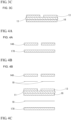
FIG. 3A is a cross-sectional view for describing a method for manufacturing the insulated circuit board shown inFIG. 1 . -
FIG. 3B is a cross-sectional view for describing the method for manufacturing the insulated circuit board shown inFIG. 1 . -
FIG. 3C is a cross-sectional view for describing the method for manufacturing the insulated circuit board shown inFIG. 1 . -
FIG. 4A is a cross-sectional view for describing the method for manufacturing the insulated circuit board shown inFIG. 1 . -
FIG. 4B is a cross-sectional view for describing the method for manufacturing the insulated circuit board shown inFIG. 1 . -
FIG. 4C is a cross-sectional view for describing the method for manufacturing the insulated circuit board shown inFIG. 1 . - Hereinafter, an embodiment of the present invention will be described with reference to the drawings.
- An
insulated circuit board 1 that is manufactured by a method for manufacturing an insulated circuit board according to the present invention is a so-called power module board as shown inFIG. 1 , and anelement 30 is mounted on a surface of theinsulated circuit board 1 as shown by a chain double-dashed line inFIG. 1 to configure apower module 100. Theelement 30 is an electronic component including a semiconductor, and a variety of semiconductor elements such as an insulated gate bipolar transistor (IGBT), a metal oxide semiconductor field effect transistor (MOSFET), and a free wheeling diode (FWD) semiconductor element are selected. - While not shown, the
element 30 is provided with an upper electrode portion on the upper portion and a lower electrode portion on the lower portion, and the lower electrode portion is bonded to the upper surface of acircuit layer 12 withsolder 31 or the like, whereby theelement 30 is mounted on the upper surface of thecircuit layer 12. The upper electrode portion of theelement 30 is connected to a circuit electrode portion or the like of thecircuit layer 12 through a lead frame or the like bonded with solder or the like. - The
insulated circuit board 1 includes aceramic substrate 11, thecircuit layer 12 bonded to one surface of theceramic substrate 11, and ametal layer 15 bonded to the other surface of theceramic substrate 11. - The
ceramic substrate 11 is a rectangular sheet-shaped insulated substrate that prevents electrical connection between thecircuit layer 12 and themetal layer 15, is formed of, for example, aluminum nitride (AlN), silicon nitride (Si3N4), a zirconia-reinforced alumina substrate, or the like, and has a thickness T5 of 0.2 mm to 1.2 mm. - The
ceramic substrate 11 of the present embodiment is formed of aluminum nitride and has a size set to 100 mm × 110 mm and a thickness T5 set to 1.0 mm. - In the example shown in
FIG. 1 and FIG. 2 , thecircuit layer 12 includes twosmall circuit layers small circuit layers ceramic substrate 11 at an interval (for example, 0.5 mm to 2.0 mm). In other words, an empty portion Ar1 having a width of 0.5 mm to 2.0 mm, to which the metal of thecircuit layer 12 is not bonded, is formed between thesmall circuit layers circuit layer 12 includes first circuit layers 13 bonded to theceramic substrate 11 and second circuit layers 14 bonded to the upper surfaces of the first circuit layers 13. - For the
first circuit layer 13, pure aluminum or an aluminum alloy having a purity of 99% by mass or more is used, and, for example, aluminum in the 1xxx series in JIS, particularly, 1N99 (having a purity of 99.99% by mass or more: so-called 4N aluminum), can be used. The thickness of thefirst circuit layer 13 is 0.2 mm or more and 0.9 mm. This is because, when the thickness of thefirst circuit layer 13 is less than 0.2 mm, the stress-buffering effect of pure aluminum or an aluminum alloy is weak, and, when the thickness of thefirst circuit layer 13 exceeds 0.9 mm, a constraint on the formation of the circuit pattern becomes large. - The
first circuit layer 13 of the present embodiment is formed of pure aluminum having a purity of 99% by mass or more and has a thickness T3 set to 0.6 mm. - The
second circuit layer 14 is formed of copper such as oxygen-free copper or a copper alloy such as a zirconium-added copper alloy, and the thickness T1 of thesecond circuit layer 14 is set to 0.65 mm or more and 2.0 mm or less. The thickness T1 of thesecond circuit layer 14 is larger than the thickness T2 of asecond metal layer 17 described below, and the thickness ratio T1/T2 is set to 1.4 or more and 3.2 or less. - The
second circuit layer 14 of the present embodiment is formed of oxygen-free copper and has a thickness T1 set to 1.0 mm. The interval between the small circuit layers 121 and 122 is set to 1.0 mm. - The
metal layer 15 includes afirst metal layer 16 that is bonded to theceramic substrate 11 and thesecond metal layer 17 that is bonded to the upper surface of thefirst metal layer 16. - Similar to the
first circuit layer 13, thefirst metal layer 16 is formed using pure aluminum or an aluminum alloy having a purity of 99% by mass or more, and the thickness T4 of thefirst metal layer 16 is 0.2 mm or more and 0.9 mm. - The
first metal layer 16 of the present embodiment is formed of pure aluminum having a purity of 99% by mass or more and has a thickness T4 set to 0.6 mm. That is, thefirst circuit layer 13 and thefirst metal layer 16 have the same composition and have the same thickness (T3=T4). - The
second metal layer 17 is formed of copper such as oxygen-free copper or a copper alloy such as a zirconium-added copper alloy, and the thickness T2 of thesecond meal layer 17 is set to 0.4 mm or more and 1.4 mm or less. The thickness T2 of thesecond metal layer 17 is smaller than the thickness T1 of thesecond circuit layer 14, and the thickness ratio T1/T2 is set to 1.4 or more and 3.2 or less. - The
second metal layer 17 of the present embodiment is formed of oxygen-free copper and has a thickness T2 set to 0.7 mm. - In the insulated
circuit board 1 configured as described above, when the bonding area of thecircuit layer 12 to theceramic substrate 11 is represented by S 1 (mm2), and the bonding area of themetal layer 15 to theceramic substrate 11 is represented by S2 (mm2), the area ratio S1/S2 is adjusted to a relationship in which the area ratio becomes 0.5 or more and 0.8 or less. Thebonding areas S 1 and S2 are both a value at 30°C. - In the present embodiment, since the
circuit layer 12 includes the small circuit layers 121 and 122, the bonding area S1 of thecircuit layer 12 is the sum of the bonding area S11 of thesmall circuit layer 121 and the bonding area S12 of thesmall circuit layer 122 to theceramic substrate 11. - Next, a method for manufacturing the insulated
circuit board 1 of the present embodiment will be described. The method for manufacturing the insulatedcircuit board 1 includes a first bonding step of bonding a metal sheet for the first circuit layers 130 that is to serve as the first circuit layers 13 and is made of aluminum or an aluminum alloy and a metal sheet for the first metal layer 150 that is made of aluminum or an aluminum alloy and is to serve as thefirst metal layer 16 to theceramic substrate 11, a circuit pattern formation step of forming a circuit pattern on the metal sheet for the first circuit layers 130 (firstcircuit layer precursor 13A) bonded by the first bonding step to form the first circuit layers 13, a metal sheet formation step of pressing copper or copper alloy sheets to form metal sheets for thesecond circuit layer 140 that are to serve as the second circuit layers 14 and to have a circuit pattern and one metal sheet for thesecond metal layer 170 that is to serve as thesecond metal layer 17, and a second bonding step of bonding the metal sheets for thesecond circuit layer 140 to the upper surfaces of the first circuit layers 13 and bonding the metal sheet for thesecond metal layer 170 to the upper surface of thefirst metal layer 16. Hereinafter, the manufacturing method will be described in order of these steps. - First, as shown in
FIG. 3A , the metal sheet for the first circuit layers 130 and the metal sheet for thefirst metal layer 160 both having the same thickness are respectively bonded to theceramic substrate 11 using an Al-Si-based brazing filler metal. Specifically, the metal sheet for the first circuit layers 130 and the metal sheet for thefirst metal layer 160 are laminated on the front surface and the back surface of theceramic substrate 11 with Al-Si-based brazing filler metal foils 18 interposed therebetween. The laminate is sandwiched between carbon sheets and heated in a vacuum under a load applied in the laminating direction, thereby bonding the metal sheet for the first circuit layers 130 and the metal sheet for thefirst metal layer 160 to theceramic substrate 11. As a result, a state, which is shown inFIG. 3B , in which the firstcircuit layer precursor 13A and thefirst metal layer 16 are respectively bonded to the front surface and the back surface of theceramic substrate 11 through the bonding portions (brazing portions) is formed. - In this step, the pressure applied in the laminating direction is preferably set to 0.3 MPa to 1.5 MPa, and the temperature is preferably set to 630°C or higher and 655°C or lower. The Al-Si-based brazing filler metal foil is preferably 5 µm to 15 µm in thickness. In addition to the Al-Si-based brazing filler metal, an Al-Ge-based brazing filler metal, an Al-Cu-based brazing filler metal, an Al-Mg-based brazing filler metal, an Al-Mn-based brazing filler metal, or an Al-Si-Mg based brazing filler metal can also be used.
- Next, a mask is printed on the surface of the first
circuit layer precursor 13A and then etched using an acidic organic solvent or the like to form a circuit pattern. This mask is provided so as to form a circuit pattern as necessary on the surface of the firstcircuit layer precursor 13A. As a result, the circuit pattern is formed on the firstcircuit layer precursor 13A, and a state in which the first circuit layers 13 are bonded to theceramic substrate 11 as shown inFIG. 3C is formed. - As shown in
FIG. 4A , rolled sheets formed of copper or a copper alloy (hereinafter, referred to as rolled copper materials) are punched by pressing to form the metal sheets for thesecond circuit layer 140 and the metal sheet for thesecond metal layer 170. Specifically, a rolled copper material having a thickness of 0.4 mm or more and 1.4 mm or less is pressed to form the metal sheet for thesecond metal layer 170 having a rectangular sheet shape (for example, 95 mm × 100 mm). In addition, rolled copper materials having a thickness of 0.65 mm or more and 2.0 mm or less are pressed to form two metal sheets for thesecond circuit layer 140 having a desired pattern shape (a rectangular sheet shape in the example shown inFIGS. 4A to 4C ). The area ratio (the same as the area ratio S1/S2) of the total area (the same as the bonding area S1) of the metal sheets for thesecond circuit layer 140 formed as described above to the area (the same as the bonding area S2) of the metal sheet for thesecond metal layer 170 is set to 0.5 or more and 0.8 or less. - Next, as shown in
FIG. 4B , each of the metal sheets for thesecond circuit layer 140 is bonded to the upper surface of thefirst circuit layer 13, and the metal sheet for thesecond metal layer 170 is bonded to the upper surface of thefirst metal layer 16. Specifically, the metal sheets for thesecond circuit layer 140 and the metal sheet for thesecond metal layer 170 are respectively laminated on the upper surfaces of the first circuit layers 14 and the upper surface of thefirst metal layer 16 with Ag-Cu-Ti-based brazing filler metal foils 18 respectively interposed between the metal sheet and the layer. The laminate is sandwiched between carbon sheets and heated in a vacuum under a load applied in the laminating direction, thereby bonding the metal sheets for thesecond circuit layer 140 to the first circuit layers 13 to form the second circuit layers 14 having the thickness T1 and bonding the metal sheet for thesecond metal layer 170 to thefirst metal layer 16 to form the second metal layer having the thickness T2. - As a result, as shown in
FIG. 4C , the insulatedcircuit board 1 in which thecircuit layer 12 is bonded by solid-phase diffusion to the front surface of theceramic substrate 11 through a bonding portion (brazing portion) and themetal layer 15 is bonded by solid-phase diffusion to the back surface of theceramic substrate 11 through a bonding portion (brazing portion) is formed. Thecircuit layer 12 is formed by laminating the first circuit layers 13 and the second circuit layers 14, and themetal layer 15 formed by laminating thefirst metal layer 16 and thesecond metal layer 17. - In this step, the pressure applied in the laminating direction is preferably set to 0.1 MPa to 1.0 MPa, and the heating temperature is preferably set to 800°C to 930°C. The Ag-Cu-Ti-based brazing filler metal foil is preferably 5 µm to 15 µm in thickness. In addition to the Ag-Cu-Ti-based brazing filler metal, a Cu-P-based brazing filler metal can also be used.
- In the insulated
circuit board 1 manufactured as described above, the thickness T1 of thesecond circuit layer 14 is 0.65 mm or more and 2.0 mm or less, the area S1/S2 of the bonding area S1 of thecircuit layer 12 to the bonding area S2 of themetal layer 15 becomes 0.5 or more and 0.8 or less, and the thickness ratio T1/T2 of the thickness T1 of thesecond circuit layer 14 to the thickness T2 of thesecond metal layer 17 becomes 1.2 or more and 1.7 or less. - Here, in the bonding portion with the
circuit layer 12 or themetal layer 15, compressive stress is generated on the front and back surfaces of theceramic substrate 11. Since the pattern is formed on the front surface to which thecircuit layer 12 is bonded, as shown inFIG. 2B , on the back surface of a circuit layer non-bonding portion Ar1 between the patterns (aregion Ar 1 in which theceramic substrate 11 is exposed due to the formation of the pattern), compressive stress is generated due to themetal layer 15, and, on the front surface, tensile stress is generated. Therefore, the ceramic substrate is likely to warp such that thecircuit layer 12 side becomes convex. In this case, as thecircuit layer 12 and themetal layer 15 become thicker, the ceramic substrate more significantly warps. - In contrast, even when a residual stress is generated in the circuit layer non-bonding portion Ar1 (the region Ar1) between the circuit patterns on the
ceramic substrate 11, since the thickness T2 of thesecond metal layer 17 is thinner than the thickness T1 of thesecond circuit layer 14, it is possible to maintain the balance between the circuit layer 12-side surface and the metal layer 15-side surface of theceramic substrate 11. Therefore, it is possible to suppress a warpage change at a high temperature during soldering. - For example, in the above-described embodiment, the first circuit layers 13 are formed by etching the first
circuit layer precursor 13A, but the present invention is not limited thereto, and a plurality of metal sheets punched by pressing may be bonded to theceramic substrate 11. - In the above-described embodiment, an example in which the insulated
circuit board 1 is used as a power module board has been described, but the insulatedcircuit board 1 can also be used as a variety of kinds of insulated boards such as a substrate for an LED element. - Next, the effects of the present invention will be described in detail using examples, but the present invention is not limited to the following examples.
- Each of specimens of Examples 1 to 7 and Comparative Examples 1 to 4 is an insulated circuit board in which a circuit layer including a first circuit layer that was made of pure aluminum and had a thickness of 0.6 mm and a second circuit layer that was made of oxygen-free copper and had a thickness T1, a first metal layer that was made of pure aluminum and had a thickness of 0.6 mm, and a second metal layer that was made of oxygen-free copper and had a thickness T2 were bonded to a 100 mm × 110 mm ceramic substrate that had a thickness of 1.0 mm and was made of aluminum nitride.
- For each specimen, the thickness T1 of the second circuit layer, the thickness T2 of the second metal layer, the thickness ratio T1/T2, and the area ratio S1/S2 of the bonding area S1 of the circuit layer to the ceramic substrate and the bonding area S2 of the metal layer are shown in Table 1. The interval between two small circuit layers that configured the circuit layer was set to 1.0 mm in all of the specimens.
- In Comparative Example 4, the circuit layer and the metal layer were provided with only the second circuit layer and the second metal layer both formed of oxygen-free copper and were not provided with any aluminum layers (the first circuit layer and the first metal layer).
- The respective configuration members were bonded together by the manufacturing method described in the above-described embodiment to produce an insulated circuit board as each specimen. In addition, in a heating test designed to apply a series of temperature changes such that a sample was heated from 30°C to 285°C and then cooled to 30°C, for each of the obtained specimens, the amount of warpage during heating to 285°C (warpage during heating) and the amount of warpage (returning warpage) at 30°C when the specimen was heated to 285°C and then cooled to 30°C were respectively measured from the metal layer side.
- The amount of warpage was obtained by measuring the change of the ceramic substrate in a rectangular range (75 mm × 85 mm range) in the center of the ceramic substrate using a Moire-type three-dimensional shape measurement instrument, and the amount of change in the amount of warpage was also obtained. The amount of warpage was expressed as a "negative" value in a case where the metal layer became concave and expressed as a "positive" value in a case where the metal layer became convex.
- For each of the insulated circuit boards of Examples 1 to 7 and Comparative Examples 1 to 4, a temperature cycle test in which the temperature was changed 500 times between -40°C and 150°C was carried out, and then whether or not there was a crack in the ceramic substrate was visually determined. At this time, in a case where there was a crack in the ceramic substrate, the insulated circuit board was evaluated as poor "B", and, in a case where there was no crack in the ceramic substrate, the insulated circuit board was evaluated as favorable "A". The results are shown in Table 1.
[Table 1] Presence or absence of aluminum layer S1/S2 T1 (mm) T2 (mm) T1/T2 Warpage at 285°C (µm) Returning warpage (µm) Amount of change (µm) Evaluation of crack in ceramic substrate Example 1 Present 0.75 1 0.45 2.22 430 380 50 A Example 2 Present 0.75 1 0.6 1.66 440 -450 890 A Example 3 Present 0.75 1 0.7 1.42 510 -430 940 A Example 4 Present 0.75 1.2 0.6 2.00 412 253 159 A Example 5 Present 0.75 1.5 0.7 2.14 385 125 260 A Example 6 Present 0.8 1 0.6 1.66 420 -358 778 A Example 7 Present 0.67 1 0.6 1.66 411 -330 741 A Comparative Example 1 Present 0.75 1 1.0 1.00 830 -710 1540 A Comparative Example 2 Present 0.75 1 0.9 1.11 760 -780 1540 A Comparative Example 3 Present 0.75 1 0.8 1.25 700 -620 1320 A Comparative Example 4 Absent 0.75 1 0.45 2.22 320 450 130 B - As is clear from Table 1, it was possible to confirm that, in a case where the area ratio S1/S2 of the bonding area S1 of the circuit layer to the bonding area S2 of the metal layer was 0.5 or more and 0.8 or less, in Examples 1 to 7 in which the thickness ratio T1/T2 was 1.4 or more and 3.2 or less, the amounts of change were as small as 1000 µm or less, and the amounts of warpage were small at a high temperature during soldering or the like in the obtained insulated circuit boards.
- In Comparative Example 4, since the area ratio S1/S2 and the thickness ratio T1/T2 were within the above-described ranges, the amount of change in the amount of warpage was small. However, since the circuit layer and the metal layer respectively did not have the first circuit layer and the first metal layer each made of aluminum or an aluminum alloy, the ceramic substrate cracked as a result of the temperature cycle test. Therefore, it was possible to confirm that, in order to suppress the cracking of the ceramic substrate, it is effective that the circuit layer and the metal layer respectively include the first circuit layer and the first metal layer that are bonded to the ceramic substrate and are made of aluminum or an aluminum alloy, the second circuit layer that is bonded to the upper surface of the first circuit layer and is made of copper or a copper alloy, and the second metal layer that is bonded to the upper surface of the first metal layer and is made of copper or a copper alloy.
- A warpage change at a high temperature caused during soldering or the like of insulated circuit boards is suppressed.
-
- 1 Insulated circuit board
- 11 Ceramic substrate
- 12 Circuit layer
- 13 First circuit layer
- 13A First circuit layer precursor
- 14 Second circuit layer
- 15 Metal layer
- 16 First metal layer
- 17 Second metal layer
- 18 Brazing filler metal foil
- 30 Element
- 31 Solder
- 100 Power module
- 121 Small circuit layer
- 122 Small circuit layer
- 130 Metal sheet for first circuit layer
- 140 Metal sheet for second circuit Layer
- 160 Metal sheet for first metal layer
- 170 Metal sheet for second metal layer
- S1 Bonding area
- S2 Bonding area
- S11 Bonding area
- S12 Bonding area
- T1 Thickness of second circuit layer
- T2 Thickness of second metal layer
- T3 Thickness of first circuit layer
- T4 Thickness of first metal layer
- T5 Thickness of ceramic substrate
- Ar1 Region (circuit layer non-bonding portion)
Claims (8)
- An insulated circuit board (1) comprising:a ceramic substrate (12);a circuit layer (12) that is bonded to one surface of the ceramic substrate (11) and on which a circuit pattern is to be formed; anda metal layer bonded to the other surface of the ceramic substrate (11),wherein the circuit layer (12) has a first circuit layer (13) that is bonded to the ceramic substrate (11) and is made of aluminum or an aluminum alloy, and a second circuit layer (14) that is bonded to an upper surface of the first circuit layer (13) and is made of copper or a copper alloy,the metal layer (15) has a first metal layer (16) that is bonded to the ceramic substrate (11) and is made of aluminum or an aluminum alloy, and a second metal layer (17) that is bonded to an upper surface of the first metal layer (16) and is made of copper or a copper alloy, characterized in thatthicknesses (T3, T4) of the first circuit layer (13) and the first metal layer (16) are equal to each other and are 0.2 mm or more and 0.9 mm or less,the second circuit layer (14) has a thickness T1 of 0.65 mm or more and 2.0 mm or less,an area ratio S1/S2 of a bonding area S1 of the circuit layer (12) to the ceramic substrate (11) to a bonding area S2 of the metal layer (15) to the ceramic substrate (11) is 0.5 or more and 0.8 or less, and a thickness ratio T1/T2 of the thickness T1 of the second circuit layer (14) to a thickness T2 of the second metal layer (17) is 1.4 or more and 3.2 or less.
- The insulated circuit board (1) according to claim 1,wherein the second circuit layer (14) is bonded by solid-phase diffusion to the upper surface of the first circuit layer (13), andthe second metal layer (17) is bonded by solid-phase diffusion to the upper surface of the first metal layer (16).
- The insulated circuit board (1) according to claim 1 or 2,
wherein the second circuit layer (14) has a thickness T1 of 1.0 mm or more and 2.0 mm or less. - The insulated circuit board (1) according to any one of claims 1 to 3,
wherein the area ratio S1/S2 is 0.6 or more and 0.8 or less. - The insulated circuit board (1) according to any one of claims 1 to 4,
wherein the thickness ratio T1/T2 is 1.8 or more and 2.5 or less. - The insulated circuit board (1) according to any one of claims 1 to 5,
wherein the first circuit layer (13) and the first metal layer (16) each have a thickness (T3, T4) of 0.2 mm or more and 0.6 mm or less. - The insulated circuit board (1) according to any one of claims 1 to 6,
wherein the circuit pattern has a circuit layer non-bonding portion (Ar1) having a width of 0.5 mm to 2.0 mm. - The insulated circuit board (1) according to any one of claims 1 to 7,
wherein the ceramic substrate (12) has a thickness of 0.2 mm to 1.2 mm.
Applications Claiming Priority (2)
| Application Number | Priority Date | Filing Date | Title |
|---|---|---|---|
| JP2018037269A JP6614256B2 (en) | 2018-03-02 | 2018-03-02 | Insulated circuit board |
| PCT/JP2019/007268 WO2019167931A1 (en) | 2018-03-02 | 2019-02-26 | Insulated circuit board |
Publications (3)
| Publication Number | Publication Date |
|---|---|
| EP3761351A1 EP3761351A1 (en) | 2021-01-06 |
| EP3761351A4 EP3761351A4 (en) | 2021-12-22 |
| EP3761351B1 true EP3761351B1 (en) | 2024-01-17 |
Family
ID=67805824
Family Applications (1)
| Application Number | Title | Priority Date | Filing Date |
|---|---|---|---|
| EP19760099.2A Active EP3761351B1 (en) | 2018-03-02 | 2019-02-26 | Insulated circuit board |
Country Status (5)
| Country | Link |
|---|---|
| US (1) | US11013107B2 (en) |
| EP (1) | EP3761351B1 (en) |
| JP (1) | JP6614256B2 (en) |
| TW (1) | TWI762771B (en) |
| WO (1) | WO2019167931A1 (en) |
Families Citing this family (1)
| Publication number | Priority date | Publication date | Assignee | Title |
|---|---|---|---|---|
| JP7467214B2 (en) | 2020-04-22 | 2024-04-15 | 新光電気工業株式会社 | Wiring board, electronic device, and method for manufacturing wiring board |
Family Cites Families (8)
| Publication number | Priority date | Publication date | Assignee | Title |
|---|---|---|---|---|
| JP4206915B2 (en) | 2002-12-27 | 2009-01-14 | 三菱マテリアル株式会社 | Power module substrate |
| JP5892281B2 (en) * | 2014-04-25 | 2016-03-23 | 三菱マテリアル株式会社 | Power module substrate with heat sink and power module |
| EP3166140B1 (en) * | 2014-07-04 | 2020-06-03 | Mitsubishi Materials Corporation | Substrate unit for power modules, and power module |
| JP6137267B2 (en) * | 2015-10-08 | 2017-05-31 | 三菱マテリアル株式会社 | Power module substrate with heat sink and power module |
| JP6613929B2 (en) * | 2016-02-01 | 2019-12-04 | 三菱マテリアル株式会社 | Metal member with Ag underlayer, insulated circuit substrate with Ag underlayer, semiconductor device, insulating circuit substrate with heat sink, and method for producing metal member with Ag underlayer |
| JP6645368B2 (en) * | 2016-06-23 | 2020-02-14 | 三菱マテリアル株式会社 | Joint body, power module substrate, method of manufacturing joined body, and method of manufacturing power module substrate |
| JP6729189B2 (en) | 2016-08-31 | 2020-07-22 | Tdk株式会社 | Terminal block |
| JP6330951B2 (en) * | 2017-05-23 | 2018-05-30 | 三菱マテリアル株式会社 | Joints for manufacturing power module substrates |
-
2018
- 2018-03-02 JP JP2018037269A patent/JP6614256B2/en active Active
-
2019
- 2019-02-26 US US16/977,269 patent/US11013107B2/en active Active
- 2019-02-26 EP EP19760099.2A patent/EP3761351B1/en active Active
- 2019-02-26 WO PCT/JP2019/007268 patent/WO2019167931A1/en active Application Filing
- 2019-02-27 TW TW108106854A patent/TWI762771B/en active
Also Published As
| Publication number | Publication date |
|---|---|
| JP2019153670A (en) | 2019-09-12 |
| WO2019167931A1 (en) | 2019-09-06 |
| US20210007217A1 (en) | 2021-01-07 |
| EP3761351A1 (en) | 2021-01-06 |
| TWI762771B (en) | 2022-05-01 |
| JP6614256B2 (en) | 2019-12-04 |
| US11013107B2 (en) | 2021-05-18 |
| CN111771275A (en) | 2020-10-13 |
| EP3761351A4 (en) | 2021-12-22 |
| TW201938514A (en) | 2019-10-01 |
Similar Documents
| Publication | Publication Date | Title |
|---|---|---|
| US8637777B2 (en) | Power module substrate having heatsink, method for manufacturing the same, power module having heatsink, and power module substrate | |
| US10937715B2 (en) | Substrate for power module, collective substrate for power modules, and method for manufacturing substrate for power module | |
| EP1345480B1 (en) | Ceramic circuit board | |
| KR20160122853A (en) | Power module substrate unit and power module | |
| EP3358615B1 (en) | Silicon nitride circuit board and semiconductor module using same | |
| EP3761764A1 (en) | Insulating circuit board | |
| EP3761351B1 (en) | Insulated circuit board | |
| WO2019189329A1 (en) | Insulated circuit board with heat sink | |
| EP3780087A1 (en) | Method of manufacturing bonded body for insulating circuit board, and bonded body for insulating circuit board | |
| EP2838326B1 (en) | Electronic device | |
| US10568214B2 (en) | Method for producing multi-level metalization on a ceramic substrate | |
| JP6330951B2 (en) | Joints for manufacturing power module substrates | |
| JP4786407B2 (en) | Power module | |
| JP2010050415A (en) | Substrate for power module and method of manufacturing the same | |
| CN111771275B (en) | Insulated circuit board | |
| EP2933831A1 (en) | Method for producing substrate for power modules | |
| KR20200112841A (en) | Method for manufacturing a power module substrate and ceramic-copper assembly | |
| JPH10242330A (en) | Substrate for power module and manufacture thereof | |
| TWI770373B (en) | Insulated circuit board with heat sink | |
| WO2023204054A1 (en) | Ceramic circuit substrate, semiconductor device, method for manufacturing ceramic circuit substrate, and method for manufacturing semiconductor device | |
| JP2015070062A (en) | Substrate for power module and method for manufacturing the same |
Legal Events
| Date | Code | Title | Description |
|---|---|---|---|
| STAA | Information on the status of an ep patent application or granted ep patent |
Free format text: STATUS: THE INTERNATIONAL PUBLICATION HAS BEEN MADE |
|
| PUAI | Public reference made under article 153(3) epc to a published international application that has entered the european phase |
Free format text: ORIGINAL CODE: 0009012 |
|
| STAA | Information on the status of an ep patent application or granted ep patent |
Free format text: STATUS: REQUEST FOR EXAMINATION WAS MADE |
|
| 17P | Request for examination filed |
Effective date: 20200914 |
|
| AK | Designated contracting states |
Kind code of ref document: A1 Designated state(s): AL AT BE BG CH CY CZ DE DK EE ES FI FR GB GR HR HU IE IS IT LI LT LU LV MC MK MT NL NO PL PT RO RS SE SI SK SM TR |
|
| AX | Request for extension of the european patent |
Extension state: BA ME |
|
| DAV | Request for validation of the european patent (deleted) | ||
| DAX | Request for extension of the european patent (deleted) | ||
| A4 | Supplementary search report drawn up and despatched |
Effective date: 20211122 |
|
| RIC1 | Information provided on ipc code assigned before grant |
Ipc: H05K 3/06 20060101ALN20211116BHEP Ipc: H05K 3/02 20060101ALN20211116BHEP Ipc: H05K 1/03 20060101ALI20211116BHEP Ipc: C04B 37/02 20060101ALI20211116BHEP Ipc: H01L 23/373 20060101ALI20211116BHEP Ipc: C04B 37/00 20060101ALI20211116BHEP Ipc: H05K 1/09 20060101ALI20211116BHEP Ipc: H05K 1/02 20060101ALI20211116BHEP Ipc: H01L 23/12 20060101ALI20211116BHEP Ipc: H01L 23/13 20060101AFI20211116BHEP |
|
| STAA | Information on the status of an ep patent application or granted ep patent |
Free format text: STATUS: EXAMINATION IS IN PROGRESS |
|
| 17Q | First examination report despatched |
Effective date: 20220610 |
|
| RIC1 | Information provided on ipc code assigned before grant |
Ipc: H05K 3/06 20060101ALN20230616BHEP Ipc: H05K 3/02 20060101ALN20230616BHEP Ipc: H05K 1/03 20060101ALI20230616BHEP Ipc: C04B 37/02 20060101ALI20230616BHEP Ipc: H01L 23/373 20060101ALI20230616BHEP Ipc: C04B 37/00 20060101ALI20230616BHEP Ipc: H05K 1/09 20060101ALI20230616BHEP Ipc: H05K 1/02 20060101ALI20230616BHEP Ipc: H01L 23/12 20060101ALI20230616BHEP Ipc: H01L 23/13 20060101AFI20230616BHEP |
|
| GRAP | Despatch of communication of intention to grant a patent |
Free format text: ORIGINAL CODE: EPIDOSNIGR1 |
|
| STAA | Information on the status of an ep patent application or granted ep patent |
Free format text: STATUS: GRANT OF PATENT IS INTENDED |
|
| RIC1 | Information provided on ipc code assigned before grant |
Ipc: H05K 3/06 20060101ALN20230814BHEP Ipc: H05K 3/02 20060101ALN20230814BHEP Ipc: H05K 1/03 20060101ALI20230814BHEP Ipc: C04B 37/02 20060101ALI20230814BHEP Ipc: H01L 23/373 20060101ALI20230814BHEP Ipc: C04B 37/00 20060101ALI20230814BHEP Ipc: H05K 1/09 20060101ALI20230814BHEP Ipc: H05K 1/02 20060101ALI20230814BHEP Ipc: H01L 23/12 20060101ALI20230814BHEP Ipc: H01L 23/13 20060101AFI20230814BHEP |
|
| INTG | Intention to grant announced |
Effective date: 20230912 |
|
| GRAS | Grant fee paid |
Free format text: ORIGINAL CODE: EPIDOSNIGR3 |
|
| GRAA | (expected) grant |
Free format text: ORIGINAL CODE: 0009210 |
|
| STAA | Information on the status of an ep patent application or granted ep patent |
Free format text: STATUS: THE PATENT HAS BEEN GRANTED |
|
| AK | Designated contracting states |
Kind code of ref document: B1 Designated state(s): AL AT BE BG CH CY CZ DE DK EE ES FI FR GB GR HR HU IE IS IT LI LT LU LV MC MK MT NL NO PL PT RO RS SE SI SK SM TR |
|
| REG | Reference to a national code |
Ref country code: GB Ref legal event code: FG4D |
|
| REG | Reference to a national code |
Ref country code: DE Ref legal event code: R096 Ref document number: 602019045243 Country of ref document: DE |
|
| REG | Reference to a national code |
Ref country code: CH Ref legal event code: EP |
|
| REG | Reference to a national code |
Ref country code: IE Ref legal event code: FG4D |