EP3761275A1 - Cash handling device - Google Patents
Cash handling device Download PDFInfo
- Publication number
- EP3761275A1 EP3761275A1 EP18908228.2A EP18908228A EP3761275A1 EP 3761275 A1 EP3761275 A1 EP 3761275A1 EP 18908228 A EP18908228 A EP 18908228A EP 3761275 A1 EP3761275 A1 EP 3761275A1
- Authority
- EP
- European Patent Office
- Prior art keywords
- composite body
- slide rail
- fixed
- placement
- module
- Prior art date
- Legal status (The legal status is an assumption and is not a legal conclusion. Google has not performed a legal analysis and makes no representation as to the accuracy of the status listed.)
- Granted
Links
Images




Classifications
-
- G—PHYSICS
- G07—CHECKING-DEVICES
- G07D—HANDLING OF COINS OR VALUABLE PAPERS, e.g. TESTING, SORTING BY DENOMINATIONS, COUNTING, DISPENSING, CHANGING OR DEPOSITING
- G07D11/00—Devices accepting coins; Devices accepting, dispensing, sorting or counting valuable papers
- G07D11/40—Device architecture, e.g. modular construction
-
- G—PHYSICS
- G07—CHECKING-DEVICES
- G07D—HANDLING OF COINS OR VALUABLE PAPERS, e.g. TESTING, SORTING BY DENOMINATIONS, COUNTING, DISPENSING, CHANGING OR DEPOSITING
- G07D11/00—Devices accepting coins; Devices accepting, dispensing, sorting or counting valuable papers
- G07D11/10—Mechanical details
-
- F—MECHANICAL ENGINEERING; LIGHTING; HEATING; WEAPONS; BLASTING
- F16—ENGINEERING ELEMENTS AND UNITS; GENERAL MEASURES FOR PRODUCING AND MAINTAINING EFFECTIVE FUNCTIONING OF MACHINES OR INSTALLATIONS; THERMAL INSULATION IN GENERAL
- F16M—FRAMES, CASINGS OR BEDS OF ENGINES, MACHINES OR APPARATUS, NOT SPECIFIC TO ENGINES, MACHINES OR APPARATUS PROVIDED FOR ELSEWHERE; STANDS; SUPPORTS
- F16M13/00—Other supports for positioning apparatus or articles; Means for steadying hand-held apparatus or articles
- F16M13/02—Other supports for positioning apparatus or articles; Means for steadying hand-held apparatus or articles for supporting on, or attaching to, an object, e.g. tree, gate, window-frame, cycle
- F16M13/022—Other supports for positioning apparatus or articles; Means for steadying hand-held apparatus or articles for supporting on, or attaching to, an object, e.g. tree, gate, window-frame, cycle repositionable
-
- G—PHYSICS
- G07—CHECKING-DEVICES
- G07D—HANDLING OF COINS OR VALUABLE PAPERS, e.g. TESTING, SORTING BY DENOMINATIONS, COUNTING, DISPENSING, CHANGING OR DEPOSITING
- G07D2201/00—Coin dispensers
-
- G—PHYSICS
- G07—CHECKING-DEVICES
- G07D—HANDLING OF COINS OR VALUABLE PAPERS, e.g. TESTING, SORTING BY DENOMINATIONS, COUNTING, DISPENSING, CHANGING OR DEPOSITING
- G07D2211/00—Paper-money handling devices
Definitions
- the present invention relates to a cash handling apparatus for performing processes such as reception and ejection of bills or coins.
- slide rails with which the heavy object can be temporarily removed from the apparatus and then returned thereto have conventionally been used.
- slide rails two slide rails provided at different heights are known wherein the slide rail provided on the side for operation of attaching or detaching a storage cassette is located at the lower position (see, for example, patent document 1).
- Patent Document 1 Japanese Patent No. 5472047
- slide rails are fixed to a heavy object by, for example, screws, and in a closing/opening operation, a stopper mechanism provided for the slide rails limits the amount of opening/closing.
- a withstand load is set for the slide rails, and no problems will be likely to occur as long as a heavy object exceeding such a load is not mounted.
- a heavier object is mounted, or when the closing/opening speed is higher, a greater impact will be given by an inertial force when the heavy object is stopped at the fully open position or fully closed position of the slide rails.
- the heavy object is a composite body consisting of a plurality of connected modules
- an impact resulting from an inertial force applied to the modules other than those held by the slide rails while opening or closing the slide rails could apply a load to, and thus break, the linkages between the modules.
- the composite body could swing in a lateral direction orthogonal to the open-close direction of the slide rails and could be broken as a result of striking the inner wall of the housing accommodating the composite body.
- An object of the present invention is to reduce the occurrence of breakage of a cash handling apparatus provided with slide rails.
- a cash handling apparatus includes a composite body that consists of a plurality of connected modules, slide rails with which the composite body is drawn out of the housing, and a holding part that is fixed to two or more adjacent surfaces among four outer surfaces of the composite body and holds the plurality of modules together.
- the above-described aspect allows for a reduction in the occurrence of breakage of a cash handling apparatus provided with slide rails.
- the present embodiment will be described with reference a bill reception-ejection apparatus 1, i.e., an example of the cash handling apparatus.
- the cash is not limited to bills but may be coins
- the handling of cash is not limited to reception and ejection of cash but may be other types of handling, such as those that include only ejection or reception of cash.
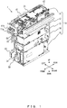
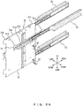
- FIG. 1 is a front perspective view illustrating the bill reception-ejection apparatus 1 with first to third slide rails 21 to 23 in a fully closed state.
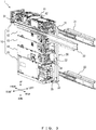
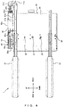
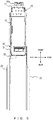
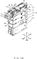
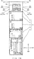
- FIGS. 2-5 are a front perspective view, a back perspective view, a left side view, and a bottom view each illustrating the bill reception-ejection apparatus 1 with the first to third slide rails 21 to 23 in the fully open state.
- the up-down direction may be a vertical direction
- the front-rear and left-right directions may be a horizontal direction.
- the bill reception-ejection apparatus 1 depicted in FIGS. 1-5 includes a composite body 10, a first slide rail 21, a second slide rail 22, a third slide rail 23, a holding part 30, a first grip bracket 41 and a second grip bracket 42, i.e., examples of brackets, and a placement-reception part 51 (see FIG. 3 ) .
- the composite body 10 is a heavy object (heavy unit) consisting of a first module 11, a second module 12, a third module 13, a fourth module 14, and a fifth module 15, which are connected in this order from the upper side in a height direction, wherein each of these modules is shaped like a rectangular solid.
- the first to fifth modules 11 to 15 may be connected such that the bottom and back surfaces of an upper module and the upper and back surfaces of a module directly thereunder are connected.
- any method can be used to connect the modules.
- the composite body 10 may include any type of modules .
- the first to fifth modules 11 to 15 described in the following are merely examples.
- the first module 11 is provided with a cash ejector 11a protruding forward for ejecting bills and a cash receiver 11b protruding forward for receiving bills.
- the first module 11 also has disposed therein a transportation unit for transporting bills, a validation unit for validating the bills, and the like.
- the second module 12 and the third module 13 accommodate bills for withdrawal among received bills.
- recycle bill accommodation parts (not illustrated) for accommodating bills sandwiched by films in a rolled manner may be disposed inside the front and rear portions of the second module 12 and the third module 13.
- the fourth module 14 accommodates bills supplied from outside for withdrawal.
- the fifth module 15 accommodates bills that are not to be used for withdrawal among received bills.
- Rear end portions of the first slide rail 21, the second slide rail 22, and the third slide rail 23 are fixed to the inner walls of a housing (not illustrated) so as to draw the composite body 10 out of the housing.
- a housing not illustrated
- Any number of slide rails may be provided, but only the three slide rails, namely the first slide rail 21, the second slide rail 22, and the third slide rail 23, will desirably be provided.
- first slide rail 21 and the second slide rail 22 are located on opposite sides of the composite body 10.
- first slide rail 21 is located on the left-side-surface side of the composite body 10
- second slide rail 22 is located on the right-side-surface side of the composite body 10.
- the third slide rail 23 is located below the first slide rail, i.e., located on the left-side-surface side of the composite body 10.
- the holding part 30 is fixed to portions of the right-side surfaces of the first slide rail 21 and the third slide rail 23 on the front-end side.
- the holding part 30 is also fixed to the left side surface of the composite body 10 (an example of the first surface) and the back surface thereof (an example of the second surface) and holds the first to fifth modules 11 to 15 together.
- the holding part 30 may be fixed to two or more adjacent surfaces of the four outer surfaces (left side and right side surfaces, front surface, and back surface) of the composite body 10.
- the holding part 30 includes a left-side-surface holding section 31, a back-surface holding section 32, and a back-surface holding section 33.
- the left-side-surface holding section 31 assumes, as depicted in FIG. 4 , a rectangular plate shape covering the left side surfaces of the first to fifth modules 11 to 15.
- the left-side-surface holding section 31 includes a placement-reception surface 31a on which placement surfaces 41b and 41c of the first grip bracket 41 (described hereinafter) are placed, catching projections 31b and 31c protruding upward such that catch sections 41d and 41e provided on the placement surfaces 41b and 41c can be caught thereon, and a fixation member 31d provided on the right-side surface.
- the fixation member 31d depicted in FIG. 6A fixes, as depicted in FIG. 4 , the left-side-surface holding section 31 to the second module 12 by means of a fixation screw 36, to the third module 13 by means of a fixation screw 37, to the fourth module 14 by means of a fixation screw 38, and to the fifth module 15 by means of a fixation screw 39.
- the left-side-surface holding section 31 has the placement-reception surface 31a fixed to the first grip bracket 41 fixed to the first module 11 and is thus fixed indirectly to the first module 11.
- the left-side-surface holding section 31 is fixed to all of the first to fifth modules 11 to 15.
- the left-side-surface holding section 31 may be fixed at least to the first module 11, i.e., the uppermost module, and the fifth module 15, i.e., the lowermost module.
- the back-surface holding section 32 is fixed to the rear edge of the left-side-surface holding section 31 and fixed to the lower edge of the back surface of the fourth module 14 by a fixation screw 34.
- the back-surface holding section 33 is fixed to the rear edge of the left-side-surface holding section 31 and fixed to the lower edge of the back surface of the fifth module 15 by a fixation screw 35.
- the modules fixed to the back-surface holding sections 32 and 33 are desirably modules other than the first module 11.
- the first module 11 is firmly fixed, owing to the first grip bracket 41 and the second grip bracket 42 fixed to the first module 11, to the first slide rail 21 and the second slide rail 22 via the holding part 30 and the placement-reception part 51, as will be described in detail hereinafter.
- the modules fixed to the back-surface holding sections 32 and 33 be modules located distant from the first module 11.
- the fourth module 14 and the fifth module 15 may be more desirably fixed to the back-surface holding sections 32 and 33 than the second module 12 and the third module 13.
- FIGS. 6A and 7A are a front perspective view and an enlarged front view illustrating the first to third slide rails 21 to 23 in a fully open state.
- FIGS. 6B and 7B are a front perspective view and an enlarged front view illustrating the composite body 10.
- FIGS. 6C and 7C are a partially enlarged front perspective view and an enlarged front view illustrating a situation in which the composite body 10 (first grip bracket 41 and second grip bracket 42) is placed on the first slide rail 21 (holding part 30) and the second slide rail 22 (placement-reception part 51) .
- the first grip bracket 41 to be fixed to the left side surface of the first module 11 as depicted in FIGS. 6B and 7B is placed on the holding part 30 depicted in FIGS. 6A and 7A
- the second grip bracket 42 to be fixed to the right side surface of the first module 11 as depicted in FIGS. 6B and 7B is placed on the placement-reception part 51 depicted in FIGS. 6A and 7A
- the first grip bracket 41 is fixed to the holding part 30, and the second grip bracket 42 is fixed to the placement-reception part 51, thereby fixing the composite body 10 to the first slide rail 21 and the second slide rail 22.
- the placement-reception part 51 is fixed to a portion of the left side surface of the second slide rail 22 on the front end side.
- the placement-reception part 51 includes a placement-reception surface 51a on which placement surfaces 42b and 42c of the second grip bracket 42 are placed and catching projections 51b and 51c protruding upward such that catch sections 42d and 42e provided on the placement surfaces 42b and 42c can be caught thereon.
- FIG. 1 depicted in FIG.
- the holding part 30 includes, as described above, the placement-reception surface 31a on which the placement surfaces 41b and 41c of the first grip bracket 41 are placed and the catching projections 31b and 31c protruding upward such that the catch sections 41d and 41e provided on the placement surfaces 41b and 41c can be caught thereon.
- the holding part 30 not only holds the first to fifth modules 11 to 15 together but also serves as a placement-reception part on which the first grip bracket 41 is placed, as with the placement-reception part 51 on which the second grip bracket 42 is placed.
- the first grip bracket 41 is fixed to the left side surface of the composite body 10 by fixation screws 41f, 41g, and 41h.
- the second grip bracket 42 is fixed to the right side surface of the composite body 10 by fixation screws 42f, 42g, and 42h.
- the second grip bracket 42 includes a grip section 42a that protrudes upward and is bent from the upper edge horizontally rightward, placement surfaces 42b and 42c that are bent horizontally rightward and to be placed on the placement-reception surface 51a of the placement-reception part 51, a catch section 42d that protrudes forward from the right end portion of the placement surface 42b, and a catch section 42e that protrudes rearward from the left end portion of the placement surface 42c. Accordingly, as depicted in FIGS.
- the placement surfaces 42b and 42c are placed on the placement-reception surface 51a of the placement-reception part 51, with the result that the second grip bracket 42 is placed via the placement-reception part 51 on the second slide rail 22 fixed to the placement-reception part 51.
- the catch sections 42d and 42e of the second grip bracket 42 are caught on the catching projections 51b and 51c of the placement-reception part 51 so as to prevent the second grip bracket 42 (composite body 10) from being dropped in a width direction (leftward direction) orthogonal to the open-close direction of the first to third slide rails 21 to 23 (front-rear direction).
- the first grip bracket 41 includes a grip section 41a that protrudes upward and is bent from the upper edge horizontally leftward, placement surfaces 41b and 41c that are bent horizontally leftward and to be placed on the placement-reception surface 31a of the left-side-surface holding section 31, a catch section 41d that protrudes forward from the left end portion of the placement surface 41b, and a catch section 41e that protrudes rearward from the left end portion of the placement surface 41c.
- the placement surfaces 41b and 41c are placed on the placement-reception surface 31a of the holding part 30, with the result that the first grip bracket 41 is placed via the holding part 30 on the first slide rail 21 fixed to the holding part 30.
- the catch sections 41d and 41e of the first grip bracket 41 are caught on the catching projections 31b and 31c of the holding part 30 so as to prevent the first grip bracket 41 (composite body 10) from being dropped in a width direction (rightward direction).
- the first grip bracket 41 may be placed directly on the first slide rail 21 without intervention of the holding part 30.
- the second grip bracket 42 may be placed directly on the second slide rail 22 without intervention of the placement-reception part 51.
- the grip section 41a of the first grip bracket 41 is located forward of the grip section 42a of the second grip bracket 42. Meanwhile, the placement surfaces 41b and 42b of the first grip bracket 41 and the second grip bracket 42 are provided forward of the grip sections 41a and 41b, and the placement surfaces 41c and 42c of the first grip bracket 41 and the second grip bracket 42 are provided rearward of the grip sections 41a and 41b.
- the placement surfaces 41b and 41c of the first grip bracket 41 are fixed to the placement-reception surface 31a of the holding part 30 by fixation screws 41i, 41j, and 41k.
- the placement surfaces 42b and 42c of the second grip bracket 42 are fixed to the placement-reception surface 51a of the placement-reception part 51 by fixation screws 42i, 42j, and 42k. Accordingly, the composite body 10 is fixed to the first slide rail 21 via the first grip bracket 41 and the holding part 30 and fixed to the second slide rail 22 via the second grip bracket 42 and the placement-reception part 51. Since the third slide rail 23 is fixed to the holding part 30 as described above, the composite body 10 can be considered to be fixed to the third slide rail 23 via the holding part 30.
- the bill reception-ejection apparatus i.e., an example of the cash handling apparatus, includes: the composite body 10 that consists of the first to fifth modules 11 to 15 connected to each other, i.e., examples of the plurality of modules; the first to third slide rails 21 to 23, i.e., examples of the slide rails with which the composite body 10 is drawn out of the housing; and the holding part 30 that is fixed to the left side surface and back surface of the composite body 10, i.e., examples of the two or more adjacent surfaces among the four outer surfaces (left side and right side surfaces, front surface, and back surface) of the composite body 10, and holds the first to fifth modules 11 to 15 together.
- the holding part 30 can reduce application of a load to the linkages between the first to fifth modules 11 to 15 that could occur due to an impact resulting from an inertial force applied to the modules when opening or closing the first to third slide rails 21 to 23, thereby preventing the linkages between the modules from being broken.
- the holding part 30 can also reduce swing of the composite body 10 in the left-right direction, thereby preventing the composite body 10 from being broken as a result of striking the inner wall of the housing. Accordingly, embodiments allow for a reduction in the occurrence of breakage of the cash handling apparatus (bill reception-ejection apparatus 1) that includes the slide rails (first to third slide rails 21 to 23).
- the first to fifth modules 11 to 15 are connected in the height direction, and the holding part 30 is fixed to the first to fifth modules 11 to 15 (at least the uppermost module and the lowermost module) at the left side surface, i.e., an example of the first surface, among the four outer surfaces (left side and right side surfaces, front surface, and back surface) of the composite body 10 and is fixed to the fourth module 14 and the fifth module 15 (an example of the at least one module) at the back surface, i.e., an example of the second surface adjacent to the first surface, among the four outer surfaces.
- the linkages between modules that tend to have an impact resulting from an inertial force applied thereto such as the fourth module 14 and the fifth module 15 that are distant from the first module 11 and indirectly connected to the first slide rail 21 and the second slide rail 22, can be reliably prevented from being broken.
- the holding part 30 is fixed only to the left side surface among the left and right side surfaces of the composite body 10, the right side surface of the composite body 10 may be used to perform maintenance of the composite body 10.
- the bill reception-ejection apparatus 1 includes only three slide rails: the first slide rail 21 and the second slide rail 22 that are located on opposite sides of the composite body 10 and the third slide 23 located below the first slide rail 21.
- swing of the composite body 10 in the left-right direction can be reduced more reliably, thereby more reliably preventing the composite body 10 from being broken as a result of striking the inner wall of the housing.
- no slide rails are disposed over or under the composite body 10, more modules can be connected to the composite body 10 in the height direction.
- the first slide rail 21 and the third slide rail 23 are fixed to the holding part 30.
- the holding part 30 fixed to the two slide rails can more reliably hold the composite body 10, so that the occurrence of breakage of the bill reception-ejection apparatus 1 can be reduced more effectively.
- the first grip bracket 41 and the second grip bracket 42 are fixed to the composite body 10 and placed directly or indirectly on the first slide rail 21 and the second slide rail 22. Accordingly, in the process of assembling the bill reception-ejection apparatus 1 with the composite body 10 placed on the first slide rail 21 and the second slide rail 22, the first grip bracket 41 can be fixed to the holding part 30, the second grip bracket 42 can be fixed to the placement-reception part 51, and the second to fifth modules 12 to 15 can be fixed to the holding part 30. Hence, a single person can assemble the bill reception-ejection apparatus 1 by himself/herself.
- the first grip bracket 41 and the second grip bracket 42 include the catch sections 41d, 41e, 42d, and 42e for preventing these brackets from being dropped in the width direction (left-right direction) orthogonal to the open-close direction of the first slide rail 21 and the second slide rail 22, with the brackets placed directly or indirectly on the first slide rail 21 and the second slide rail 22. Accordingly, the composite body 10 (first grip bracket 41 and second grip bracket 42) can be prevented from being dropped (falling) even if the first slide rail 21 or the second slide rail 22 is warped in the width direction.
- the first slide rail 21 and the third slide rail 23, i.e., examples of the at least one slide rail, are fixed to the holding part 30, and the first grip bracket 41, i.e., an example of the at least one bracket, is placed on the first slide rail 21 via the holding part 30.
- the holding part 30 can also serve as a placement-reception part which is fixed to the first slide rail 21 and on which the first grip bracket 41 is placed, as with the placement-reception part 51 which is fixed to the second slide rail 22 and on which the second grip bracket 42 is placed. Accordingly, the composite body 10 (first grip bracket 41) can be reliably placed on the first slide rail 21 (holding part 30) with the simple configuration in which the holding part 30 holding the first to fifth modules 11 to 15 together is used.
- the present invention is not simply limited to the embodiments described herein. Components of the embodiments may be embodied in a varied manner in an implementation phase without departing from the gist of the invention. A plurality of components disclosed with reference to the described embodiments may be combined, as appropriate, to achieve various inventions. For example, all of the components indicated with reference to embodiments may be combined as appropriate. Accordingly, various variations and applications can be provided without departing from the gist of the invention.
Landscapes
- Physics & Mathematics (AREA)
- General Physics & Mathematics (AREA)
- Control Of Vending Devices And Auxiliary Devices For Vending Devices (AREA)
- Engineering & Computer Science (AREA)
- General Engineering & Computer Science (AREA)
- Casings For Electric Apparatus (AREA)
- Mechanical Engineering (AREA)
- Pile Receivers (AREA)
- Sheets, Magazines, And Separation Thereof (AREA)
Abstract
Description
- The present invention relates to a cash handling apparatus for performing processes such as reception and ejection of bills or coins.
- To easily and safely perform tasks such as maintenance of a heavy object mounted on a cash handling apparatus, slide rails with which the heavy object can be temporarily removed from the apparatus and then returned thereto have conventionally been used. As examples of such slide rails, two slide rails provided at different heights are known wherein the slide rail provided on the side for operation of attaching or detaching a storage cassette is located at the lower position (see, for example, patent document 1).
- Patent Document 1: Japanese Patent No.
5472047 - In the meantime, slide rails are fixed to a heavy object by, for example, screws, and in a closing/opening operation, a stopper mechanism provided for the slide rails limits the amount of opening/closing. As a general rule, a withstand load is set for the slide rails, and no problems will be likely to occur as long as a heavy object exceeding such a load is not mounted. However, when a heavier object is mounted, or when the closing/opening speed is higher, a greater impact will be given by an inertial force when the heavy object is stopped at the fully open position or fully closed position of the slide rails.
- Accordingly, when the heavy object is a composite body consisting of a plurality of connected modules, an impact resulting from an inertial force applied to the modules other than those held by the slide rails while opening or closing the slide rails could apply a load to, and thus break, the linkages between the modules. The composite body could swing in a lateral direction orthogonal to the open-close direction of the slide rails and could be broken as a result of striking the inner wall of the housing accommodating the composite body.
- An object of the present invention is to reduce the occurrence of breakage of a cash handling apparatus provided with slide rails.
- In one aspect, a cash handling apparatus includes a composite body that consists of a plurality of connected modules, slide rails with which the composite body is drawn out of the housing, and a holding part that is fixed to two or more adjacent surfaces among four outer surfaces of the composite body and holds the plurality of modules together.
- The above-described aspect allows for a reduction in the occurrence of breakage of a cash handling apparatus provided with slide rails.
-
-
FIG. 1 is a front perspective view illustrating a bill reception-ejection apparatus in a slide-rail fully closed state; -
FIG. 2 is a front perspective view illustrating a bill reception-ejection apparatus in a slide-rail fully open state; -
FIG. 3 is a back perspective view illustrating a bill reception-ejection apparatus in a slide-rail fully open state; -
FIG. 4 is a left side view illustrating a bill reception-ejection apparatus in a slide-rail fully open state; -
FIG. 5 is a bottom view illustrating a bill reception-ejection apparatus in a slide-rail fully open state; -
FIG. 6A is a front perspective view illustrating slide rails in a fully open state; -
FIG. 6B is a front perspective view illustrating a composite body; -
FIG. 6C is a partially enlarged front perspective view illustrating a situation in which a composite body (grip bracket) is placed on slide rails (holding part and placement-reception part); -
FIG. 7A is an enlarged front view illustrating slide rails in a fully open state; -
FIG. 7B is an enlarged front view illustrating a composite body; and -
FIG. 7C is an enlarged front view illustrating a situation in which a composite body (grip brackets) is placed on slide rails (holding part and placement-reception part). - The following describes a cash handling apparatus in accordance with an embodiment of the present invention by referring to the drawings. The present embodiment will be described with reference a bill reception-
ejection apparatus 1, i.e., an example of the cash handling apparatus. However, the cash is not limited to bills but may be coins, and the handling of cash is not limited to reception and ejection of cash but may be other types of handling, such as those that include only ejection or reception of cash. -
FIG. 1 is a front perspective view illustrating the bill reception-ejection apparatus 1 with first tothird slide rails 21 to 23 in a fully closed state. -
FIGS. 2-5 are a front perspective view, a back perspective view, a left side view, and a bottom view each illustrating the bill reception-ejection apparatus 1 with the first tothird slide rails 21 to 23 in the fully open state. - Regarding an up-down direction, a front-rear direction, and a left-right direction indicated in
FIGS. 1-5 andFIGS. 6A-6C andFIGS. 7A-7C , which will be described hereinafter, for example, the up-down direction may be a vertical direction, and the front-rear and left-right directions may be a horizontal direction. - The bill reception-
ejection apparatus 1 depicted inFIGS. 1-5 includes acomposite body 10, afirst slide rail 21, asecond slide rail 22, athird slide rail 23, aholding part 30, afirst grip bracket 41 and asecond grip bracket 42, i.e., examples of brackets, and a placement-reception part 51 (seeFIG. 3 ) . - The
composite body 10 is a heavy object (heavy unit) consisting of afirst module 11, asecond module 12, athird module 13, afourth module 14, and afifth module 15, which are connected in this order from the upper side in a height direction, wherein each of these modules is shaped like a rectangular solid. For example, the first tofifth modules 11 to 15 may be connected such that the bottom and back surfaces of an upper module and the upper and back surfaces of a module directly thereunder are connected. However, any method can be used to connect the modules. As long as thecomposite body 10 includes a plurality of modules, thecomposite body 10 may include any type of modules . Hence, the first tofifth modules 11 to 15 described in the following are merely examples. - The
first module 11 is provided with acash ejector 11a protruding forward for ejecting bills and acash receiver 11b protruding forward for receiving bills. Thefirst module 11 also has disposed therein a transportation unit for transporting bills, a validation unit for validating the bills, and the like. - The
second module 12 and thethird module 13 accommodate bills for withdrawal among received bills. For example, recycle bill accommodation parts (not illustrated) for accommodating bills sandwiched by films in a rolled manner may be disposed inside the front and rear portions of thesecond module 12 and thethird module 13. - The
fourth module 14 accommodates bills supplied from outside for withdrawal. - The
fifth module 15 accommodates bills that are not to be used for withdrawal among received bills. - Rear end portions of the
first slide rail 21, thesecond slide rail 22, and thethird slide rail 23 are fixed to the inner walls of a housing (not illustrated) so as to draw thecomposite body 10 out of the housing. Any number of slide rails may be provided, but only the three slide rails, namely thefirst slide rail 21, thesecond slide rail 22, and thethird slide rail 23, will desirably be provided. - As depicted in
FIGS. 2 and3 , thefirst slide rail 21 and thesecond slide rail 22 are located on opposite sides of thecomposite body 10. In particular, thefirst slide rail 21 is located on the left-side-surface side of thecomposite body 10, and thesecond slide rail 22 is located on the right-side-surface side of thecomposite body 10. Thethird slide rail 23 is located below the first slide rail, i.e., located on the left-side-surface side of thecomposite body 10. - As depicted in
FIG. 3 , theholding part 30 is fixed to portions of the right-side surfaces of thefirst slide rail 21 and thethird slide rail 23 on the front-end side. Theholding part 30 is also fixed to the left side surface of the composite body 10 (an example of the first surface) and the back surface thereof (an example of the second surface) and holds the first tofifth modules 11 to 15 together. In this way, theholding part 30 may be fixed to two or more adjacent surfaces of the four outer surfaces (left side and right side surfaces, front surface, and back surface) of thecomposite body 10. - The holding
part 30 includes a left-side-surface holding section 31, a back-surface holding section 32, and a back-surface holding section 33. - The left-side-
surface holding section 31 assumes, as depicted inFIG. 4 , a rectangular plate shape covering the left side surfaces of the first tofifth modules 11 to 15. As depicted inFIG. 6A , the left-side-surface holding section 31 includes a placement-reception surface 31a on which placement surfaces 41b and 41c of the first grip bracket 41 (described hereinafter) are placed, catchingprojections catch sections fixation member 31d provided on the right-side surface. - The
fixation member 31d depicted inFIG. 6A fixes, as depicted inFIG. 4 , the left-side-surface holding section 31 to thesecond module 12 by means of afixation screw 36, to thethird module 13 by means of afixation screw 37, to thefourth module 14 by means of afixation screw 38, and to thefifth module 15 by means of afixation screw 39. - As will be described in detail hereinafter, the left-side-
surface holding section 31 has the placement-reception surface 31a fixed to thefirst grip bracket 41 fixed to thefirst module 11 and is thus fixed indirectly to thefirst module 11. - As described above, the left-side-
surface holding section 31 is fixed to all of the first tofifth modules 11 to 15. The left-side-surface holding section 31 may be fixed at least to thefirst module 11, i.e., the uppermost module, and thefifth module 15, i.e., the lowermost module. - As depicted in
FIG. 3 , the back-surface holding section 32 is fixed to the rear edge of the left-side-surface holding section 31 and fixed to the lower edge of the back surface of thefourth module 14 by afixation screw 34. The back-surface holding section 33 is fixed to the rear edge of the left-side-surface holding section 31 and fixed to the lower edge of the back surface of thefifth module 15 by afixation screw 35. The modules fixed to the back-surface holding sections first module 11. This is because thefirst module 11 is firmly fixed, owing to thefirst grip bracket 41 and thesecond grip bracket 42 fixed to thefirst module 11, to thefirst slide rail 21 and thesecond slide rail 22 via the holdingpart 30 and the placement-reception part 51, as will be described in detail hereinafter. It will be more desirable that the modules fixed to the back-surface holding sections first module 11. For example, thefourth module 14 and thefifth module 15 may be more desirably fixed to the back-surface holding sections second module 12 and thethird module 13. -
FIGS. 6A and7A are a front perspective view and an enlarged front view illustrating the first to third slide rails 21 to 23 in a fully open state. -
FIGS. 6B and7B are a front perspective view and an enlarged front view illustrating thecomposite body 10. -
FIGS. 6C and7C are a partially enlarged front perspective view and an enlarged front view illustrating a situation in which the composite body 10 (first grip bracket 41 and second grip bracket 42) is placed on the first slide rail 21 (holding part 30) and the second slide rail 22 (placement-reception part 51) . - In a process of assembling the bill reception-
ejection apparatus 1 such as the mounting or replacing of thecomposite body 10, thefirst grip bracket 41 to be fixed to the left side surface of thefirst module 11 as depicted inFIGS. 6B and7B is placed on the holdingpart 30 depicted inFIGS. 6A and7A , and thesecond grip bracket 42 to be fixed to the right side surface of thefirst module 11 as depicted inFIGS. 6B and7B is placed on the placement-reception part 51 depicted inFIGS. 6A and7A . Then, thefirst grip bracket 41 is fixed to the holdingpart 30, and thesecond grip bracket 42 is fixed to the placement-reception part 51, thereby fixing thecomposite body 10 to thefirst slide rail 21 and thesecond slide rail 22. - As depicted in
FIGS. 6A and7A , the placement-reception part 51 is fixed to a portion of the left side surface of thesecond slide rail 22 on the front end side. As depicted inFIGS. 6C and7C , the placement-reception part 51 includes a placement-reception surface 51a on which placement surfaces 42b and 42c of thesecond grip bracket 42 are placed and catchingprojections catch sections FIG. 7C , the holdingpart 30 includes, as described above, the placement-reception surface 31a on which the placement surfaces 41b and 41c of thefirst grip bracket 41 are placed and the catchingprojections catch sections part 30 not only holds the first tofifth modules 11 to 15 together but also serves as a placement-reception part on which thefirst grip bracket 41 is placed, as with the placement-reception part 51 on which thesecond grip bracket 42 is placed. - As depicted in
FIG. 7B , thefirst grip bracket 41 is fixed to the left side surface of thecomposite body 10 byfixation screws FIGS. 6B and7B , thesecond grip bracket 42 is fixed to the right side surface of thecomposite body 10 byfixation screws - As depicted in
FIGS. 6B and7B , thesecond grip bracket 42 includes agrip section 42a that protrudes upward and is bent from the upper edge horizontally rightward, placement surfaces 42b and 42c that are bent horizontally rightward and to be placed on the placement-reception surface 51a of the placement-reception part 51, acatch section 42d that protrudes forward from the right end portion of theplacement surface 42b, and acatch section 42e that protrudes rearward from the left end portion of theplacement surface 42c. Accordingly, as depicted inFIGS. 6C and7C , the placement surfaces 42b and 42c are placed on the placement-reception surface 51a of the placement-reception part 51, with the result that thesecond grip bracket 42 is placed via the placement-reception part 51 on thesecond slide rail 22 fixed to the placement-reception part 51. - The
catch sections second grip bracket 42 are caught on the catchingprojections reception part 51 so as to prevent the second grip bracket 42 (composite body 10) from being dropped in a width direction (leftward direction) orthogonal to the open-close direction of the first to third slide rails 21 to 23 (front-rear direction). - As depicted in
FIG. 7B , thefirst grip bracket 41 includes agrip section 41a that protrudes upward and is bent from the upper edge horizontally leftward, placement surfaces 41b and 41c that are bent horizontally leftward and to be placed on the placement-reception surface 31a of the left-side-surface holding section 31, acatch section 41d that protrudes forward from the left end portion of theplacement surface 41b, and acatch section 41e that protrudes rearward from the left end portion of theplacement surface 41c. Accordingly, as depicted inFIG. 7C , the placement surfaces 41b and 41c are placed on the placement-reception surface 31a of the holdingpart 30, with the result that thefirst grip bracket 41 is placed via the holdingpart 30 on thefirst slide rail 21 fixed to the holdingpart 30. - The
catch sections first grip bracket 41 are caught on the catchingprojections part 30 so as to prevent the first grip bracket 41 (composite body 10) from being dropped in a width direction (rightward direction). - The
first grip bracket 41 may be placed directly on thefirst slide rail 21 without intervention of the holdingpart 30. Thesecond grip bracket 42 may be placed directly on thesecond slide rail 22 without intervention of the placement-reception part 51. - As depicted in
FIG. 6B , thegrip section 41a of thefirst grip bracket 41 is located forward of thegrip section 42a of thesecond grip bracket 42. Meanwhile, the placement surfaces 41b and 42b of thefirst grip bracket 41 and thesecond grip bracket 42 are provided forward of thegrip sections first grip bracket 41 and thesecond grip bracket 42 are provided rearward of thegrip sections - As depicted in
FIG. 7C , the placement surfaces 41b and 41c of thefirst grip bracket 41 are fixed to the placement-reception surface 31a of the holdingpart 30 byfixation screws 41i, 41j, and 41k. As depicted inFIGS 6C and7C , the placement surfaces 42b and 42c of thesecond grip bracket 42 are fixed to the placement-reception surface 51a of the placement-reception part 51 byfixation screws composite body 10 is fixed to thefirst slide rail 21 via thefirst grip bracket 41 and the holdingpart 30 and fixed to thesecond slide rail 22 via thesecond grip bracket 42 and the placement-reception part 51. Since thethird slide rail 23 is fixed to the holdingpart 30 as described above, thecomposite body 10 can be considered to be fixed to thethird slide rail 23 via the holdingpart 30. - In the embodiments described above, the bill reception-
ejection apparatus 1, i.e., an example of the cash handling apparatus, includes: thecomposite body 10 that consists of the first tofifth modules 11 to 15 connected to each other, i.e., examples of the plurality of modules; the first to third slide rails 21 to 23, i.e., examples of the slide rails with which thecomposite body 10 is drawn out of the housing; and the holdingpart 30 that is fixed to the left side surface and back surface of thecomposite body 10, i.e., examples of the two or more adjacent surfaces among the four outer surfaces (left side and right side surfaces, front surface, and back surface) of thecomposite body 10, and holds the first tofifth modules 11 to 15 together. - Accordingly, the holding
part 30 can reduce application of a load to the linkages between the first tofifth modules 11 to 15 that could occur due to an impact resulting from an inertial force applied to the modules when opening or closing the first to third slide rails 21 to 23, thereby preventing the linkages between the modules from being broken. The holdingpart 30 can also reduce swing of thecomposite body 10 in the left-right direction, thereby preventing thecomposite body 10 from being broken as a result of striking the inner wall of the housing. Accordingly, embodiments allow for a reduction in the occurrence of breakage of the cash handling apparatus (bill reception-ejection apparatus 1) that includes the slide rails (first to third slide rails 21 to 23). - In embodiments, the first to
fifth modules 11 to 15 are connected in the height direction, and the holdingpart 30 is fixed to the first tofifth modules 11 to 15 (at least the uppermost module and the lowermost module) at the left side surface, i.e., an example of the first surface, among the four outer surfaces (left side and right side surfaces, front surface, and back surface) of thecomposite body 10 and is fixed to thefourth module 14 and the fifth module 15 (an example of the at least one module) at the back surface, i.e., an example of the second surface adjacent to the first surface, among the four outer surfaces. Accordingly, the linkages between modules that tend to have an impact resulting from an inertial force applied thereto, such as thefourth module 14 and thefifth module 15 that are distant from thefirst module 11 and indirectly connected to thefirst slide rail 21 and thesecond slide rail 22, can be reliably prevented from being broken. When the holdingpart 30 is fixed only to the left side surface among the left and right side surfaces of thecomposite body 10, the right side surface of thecomposite body 10 may be used to perform maintenance of thecomposite body 10. - In embodiments, the bill reception-
ejection apparatus 1 includes only three slide rails: thefirst slide rail 21 and thesecond slide rail 22 that are located on opposite sides of thecomposite body 10 and thethird slide 23 located below thefirst slide rail 21. Thus, swing of thecomposite body 10 in the left-right direction can be reduced more reliably, thereby more reliably preventing thecomposite body 10 from being broken as a result of striking the inner wall of the housing. In addition, since no slide rails are disposed over or under thecomposite body 10, more modules can be connected to thecomposite body 10 in the height direction. - In embodiments, the
first slide rail 21 and thethird slide rail 23 are fixed to the holdingpart 30. Thus, the holdingpart 30 fixed to the two slide rails can more reliably hold thecomposite body 10, so that the occurrence of breakage of the bill reception-ejection apparatus 1 can be reduced more effectively. - In embodiments, the
first grip bracket 41 and thesecond grip bracket 42, i.e., examples of the bracket, are fixed to thecomposite body 10 and placed directly or indirectly on thefirst slide rail 21 and thesecond slide rail 22. Accordingly, in the process of assembling the bill reception-ejection apparatus 1 with thecomposite body 10 placed on thefirst slide rail 21 and thesecond slide rail 22, thefirst grip bracket 41 can be fixed to the holdingpart 30, thesecond grip bracket 42 can be fixed to the placement-reception part 51, and the second tofifth modules 12 to 15 can be fixed to the holdingpart 30. Hence, a single person can assemble the bill reception-ejection apparatus 1 by himself/herself. - In embodiments, the
first grip bracket 41 and thesecond grip bracket 42 include thecatch sections first slide rail 21 and thesecond slide rail 22, with the brackets placed directly or indirectly on thefirst slide rail 21 and thesecond slide rail 22. Accordingly, the composite body 10 (first grip bracket 41 and second grip bracket 42) can be prevented from being dropped (falling) even if thefirst slide rail 21 or thesecond slide rail 22 is warped in the width direction. - In embodiments, the
first slide rail 21 and thethird slide rail 23, i.e., examples of the at least one slide rail, are fixed to the holdingpart 30, and thefirst grip bracket 41, i.e., an example of the at least one bracket, is placed on thefirst slide rail 21 via the holdingpart 30. Thus, the holdingpart 30 can also serve as a placement-reception part which is fixed to thefirst slide rail 21 and on which thefirst grip bracket 41 is placed, as with the placement-reception part 51 which is fixed to thesecond slide rail 22 and on which thesecond grip bracket 42 is placed. Accordingly, the composite body 10 (first grip bracket 41) can be reliably placed on the first slide rail 21 (holding part 30) with the simple configuration in which the holdingpart 30 holding the first tofifth modules 11 to 15 together is used. - The present invention is not simply limited to the embodiments described herein. Components of the embodiments may be embodied in a varied manner in an implementation phase without departing from the gist of the invention. A plurality of components disclosed with reference to the described embodiments may be combined, as appropriate, to achieve various inventions. For example, all of the components indicated with reference to embodiments may be combined as appropriate. Accordingly, various variations and applications can be provided without departing from the gist of the invention.
-
- 1: Bill reception-ejection apparatus (cash handling apparatus)
- 10: Composite body
- 11: First module
- 11a: Cash ejector
- 11b: Cash receiver
- 12: Second module
- 13: Third module
- 14: Fourth module
- 15: Fifth module
- 21: First slide rail
- 22: Second slide rail
- 23: Third slide rail
- 30: Holding part
- 31: Left-side-surface holding section
- 31a: Placement-reception surface
- 31b, 31c: Catching projection
- 31d: Fixation member
- 32, 33: Back-surface holding section
- 34-39: Fixation screw
- 41: First grip bracket (bracket)
- 41a: Grip section
- 41b, 41c: Placement surface
- 41d, 41e: Catch section
- 41f-41k: Fixation screw
- 42: Second grip bracket (bracket)
- 42a: Grip section
- 41b, 42c: Placement surface
- 42d, 42e: Catch section
- 42f-42k: Fixation screw
- 51: Placement-reception surface
- 51a: Placement-reception surface
- 51b, 51c: Catching projection
Claims (7)
- A cash handling apparatus comprising:a composite body that consists of a plurality of connected modules;slide rails with which the composite body is drawn out of the housing; anda holding part that is fixed to two or more adjacent surfaces among four outer surfaces of the composite body and holds the plurality of modules together.
- The cash handling apparatus of claim 1, wherein
the plurality of modules are connected in a height direction, and
the holding part is fixed to at least an uppermost module and a lowermost module of the plurality of modules at a first surface of the four outer surfaces of the composite body and is fixed to at least one of the modules at a second surface adjacent to the first surface among the four outer surfaces. - The cash handling apparatus of claim 1 or 2, wherein
the slide rails include only three slide rails, the three slide rails being first and second slide rails located on opposite sides of the composite body and a third slide rail located below the first slide rail. - The cash handling apparatus of claim 3, wherein
the first slide rail and the third slide rail are fixed to the holding part. - The cash handling apparatus of any one of claims 1-4, further comprising:
brackets that are fixed to the composite body and placed directly or indirectly on the slide rails. - The cash handling apparatus of claim 5, wherein
the brackets include catch sections for preventing the brackets from being dropped in a width direction orthogonal to an open-close direction of the slide rails, with the brackets placed directly or indirectly on the slide rails. - The cash handling apparatus of claim 5 or 6, wherein
at least one of the slide rails is fixed to the holding part, and
at least one of the brackets is placed on the slide rail via the holding part.
Applications Claiming Priority (1)
| Application Number | Priority Date | Filing Date | Title |
|---|---|---|---|
| PCT/JP2018/007212 WO2019167117A1 (en) | 2018-02-27 | 2018-02-27 | Cash handling device |
Publications (3)
| Publication Number | Publication Date |
|---|---|
| EP3761275A1 true EP3761275A1 (en) | 2021-01-06 |
| EP3761275A4 EP3761275A4 (en) | 2021-10-13 |
| EP3761275B1 EP3761275B1 (en) | 2025-12-31 |
Family
ID=67805984
Family Applications (1)
| Application Number | Title | Priority Date | Filing Date |
|---|---|---|---|
| EP18908228.2A Active EP3761275B1 (en) | 2018-02-27 | 2018-02-27 | CASH HANDLING DEVICE |
Country Status (5)
| Country | Link |
|---|---|
| US (1) | US11568701B2 (en) |
| EP (1) | EP3761275B1 (en) |
| JP (1) | JP6858924B2 (en) |
| CA (1) | CA3090369C (en) |
| WO (1) | WO2019167117A1 (en) |
Families Citing this family (2)
| Publication number | Priority date | Publication date | Assignee | Title |
|---|---|---|---|---|
| CN111009071B (en) * | 2019-12-23 | 2023-04-11 | 山东新北洋信息技术股份有限公司 | Cash recycling apparatus |
| JP2023043474A (en) * | 2021-09-16 | 2023-03-29 | グローリー株式会社 | Paper sheet storage device and paper sheet processing device |
Family Cites Families (12)
| Publication number | Priority date | Publication date | Assignee | Title |
|---|---|---|---|---|
| DE4039396A1 (en) * | 1990-12-10 | 1992-06-11 | Ibm | CASE FOR RECORDING AT LEAST ONE CASSETTE CONTAINING IN PARTICULAR PAPER MONEY |
| ES2231456T3 (en) | 2000-01-24 | 2005-05-16 | Wincor Nixdorf International Gmbh | ATM. |
| JP4087142B2 (en) * | 2002-04-17 | 2008-05-21 | グローリー株式会社 | Paper sheet processing equipment |
| JP4299017B2 (en) * | 2003-02-10 | 2009-07-22 | 株式会社高見沢サイバネティックス | Device withdrawal mechanism, money handling device and transaction device |
| JP5215251B2 (en) * | 2009-06-29 | 2013-06-19 | 富士通フロンテック株式会社 | Shock absorber |
| US8480076B2 (en) * | 2009-09-30 | 2013-07-09 | Ncr Corporation | Media handling |
| JP5472047B2 (en) | 2010-11-10 | 2014-04-16 | 沖電気工業株式会社 | Banknote deposit and withdrawal machine |
| JP2012226494A (en) * | 2011-04-18 | 2012-11-15 | Glory Ltd | Sheet paper processing device |
| IN2014DN03273A (en) * | 2011-10-28 | 2015-05-22 | Hitachi Omron Terminal Solutions Corp | |
| JP6438642B2 (en) * | 2012-12-20 | 2018-12-19 | 沖電気工業株式会社 | Paper sheet handling equipment |
| JP6143364B2 (en) * | 2014-02-20 | 2017-06-07 | 富士通フロンテック株式会社 | Slide rail stopper mechanism |
| TWI607416B (en) * | 2016-12-08 | 2017-12-01 | Masterwork Automodules Tech Corp Ltd | Paper sheet handling apparatus |
-
2018
- 2018-02-27 JP JP2020503123A patent/JP6858924B2/en active Active
- 2018-02-27 CA CA3090369A patent/CA3090369C/en active Active
- 2018-02-27 WO PCT/JP2018/007212 patent/WO2019167117A1/en not_active Ceased
- 2018-02-27 EP EP18908228.2A patent/EP3761275B1/en active Active
-
2020
- 2020-08-04 US US16/984,390 patent/US11568701B2/en active Active
Also Published As
| Publication number | Publication date |
|---|---|
| WO2019167117A1 (en) | 2019-09-06 |
| US11568701B2 (en) | 2023-01-31 |
| CA3090369A1 (en) | 2019-09-06 |
| EP3761275A4 (en) | 2021-10-13 |
| JP6858924B2 (en) | 2021-04-14 |
| EP3761275B1 (en) | 2025-12-31 |
| CA3090369C (en) | 2023-09-26 |
| JPWO2019167117A1 (en) | 2020-10-22 |
| US20200364966A1 (en) | 2020-11-19 |
Similar Documents
| Publication | Publication Date | Title |
|---|---|---|
| RU2491643C1 (en) | Document handling device having verification device detachably attached thereto | |
| EP3197252B1 (en) | Slide rail assembly and guiding mechanism thereof | |
| US11568701B2 (en) | Cash handling apparatus | |
| CN218967553U (en) | Card type certificate box | |
| US20130149028A1 (en) | Locking device | |
| CN102870142A (en) | Banknote deposit and dispensing machine | |
| JP5199549B2 (en) | Amusement machine platform | |
| KR20130078863A (en) | Module withdrawing structure for automatic teller machine | |
| KR100984555B1 (en) | Media cassette automatic switchgear of media dispenser | |
| US20250320073A1 (en) | Card receiving system for a card processing machine | |
| JP5228814B2 (en) | Bill recognition device | |
| US20260036934A1 (en) | Image forming apparatus | |
| US10820443B2 (en) | Tray unit | |
| WO2025169610A1 (en) | Storage case | |
| KR20060005555A (en) | computer | |
| JP6853564B2 (en) | Studs | |
| JP2018068737A (en) | Intermediate post | |
| JP5480942B2 (en) | Game machine | |
| JP2000149519A (en) | HDD device | |
| JP2025030513A (en) | Document storage and document storage systems | |
| JP2002074487A (en) | Vending machine cash processing equipment | |
| JP5779261B2 (en) | Game machine | |
| JPH0750493A (en) | Mounting structure of drawer type housing | |
| KR20190026123A (en) | Upper body anti-shaking structure of ATM | |
| WO2020095701A1 (en) | Electronic device, board holding member, method for taking out and putting in circuit board |
Legal Events
| Date | Code | Title | Description |
|---|---|---|---|
| STAA | Information on the status of an ep patent application or granted ep patent |
Free format text: STATUS: THE INTERNATIONAL PUBLICATION HAS BEEN MADE |
|
| PUAI | Public reference made under article 153(3) epc to a published international application that has entered the european phase |
Free format text: ORIGINAL CODE: 0009012 |
|
| STAA | Information on the status of an ep patent application or granted ep patent |
Free format text: STATUS: REQUEST FOR EXAMINATION WAS MADE |
|
| 17P | Request for examination filed |
Effective date: 20200814 |
|
| AK | Designated contracting states |
Kind code of ref document: A1 Designated state(s): AL AT BE BG CH CY CZ DE DK EE ES FI FR GB GR HR HU IE IS IT LI LT LU LV MC MK MT NL NO PL PT RO RS SE SI SK SM TR |
|
| AX | Request for extension of the european patent |
Extension state: BA ME |
|
| DAV | Request for validation of the european patent (deleted) | ||
| DAX | Request for extension of the european patent (deleted) | ||
| A4 | Supplementary search report drawn up and despatched |
Effective date: 20210910 |
|
| RIC1 | Information provided on ipc code assigned before grant |
Ipc: G07D 9/00 20060101AFI20210906BHEP |
|
| STAA | Information on the status of an ep patent application or granted ep patent |
Free format text: STATUS: EXAMINATION IS IN PROGRESS |
|
| 17Q | First examination report despatched |
Effective date: 20230726 |
|
| REG | Reference to a national code |
Ref country code: DE Ref legal event code: R079 Free format text: PREVIOUS MAIN CLASS: G07D0009000000 Ipc: G07D0011100000 Ref country code: DE Ref legal event code: R079 Ref document number: 602018088367 Country of ref document: DE Free format text: PREVIOUS MAIN CLASS: G07D0009000000 Ipc: G07D0011100000 |
|
| GRAP | Despatch of communication of intention to grant a patent |
Free format text: ORIGINAL CODE: EPIDOSNIGR1 |
|
| RIC1 | Information provided on ipc code assigned before grant |
Ipc: G07D 11/10 20190101AFI20250716BHEP Ipc: G07D 11/40 20190101ALI20250716BHEP |
|
| STAA | Information on the status of an ep patent application or granted ep patent |
Free format text: STATUS: GRANT OF PATENT IS INTENDED |
|
| INTG | Intention to grant announced |
Effective date: 20250821 |
|
| GRAS | Grant fee paid |
Free format text: ORIGINAL CODE: EPIDOSNIGR3 |
|
| GRAA | (expected) grant |
Free format text: ORIGINAL CODE: 0009210 |
|
| STAA | Information on the status of an ep patent application or granted ep patent |
Free format text: STATUS: THE PATENT HAS BEEN GRANTED |
|
| AK | Designated contracting states |
Kind code of ref document: B1 Designated state(s): AL AT BE BG CH CY CZ DE DK EE ES FI FR GB GR HR HU IE IS IT LI LT LU LV MC MK MT NL NO PL PT RO RS SE SI SK SM TR |
|
| REG | Reference to a national code |
Ref country code: CH Ref legal event code: F10 Free format text: ST27 STATUS EVENT CODE: U-0-0-F10-F00 (AS PROVIDED BY THE NATIONAL OFFICE) Effective date: 20251231 Ref country code: GB Ref legal event code: FG4D |
|
| REG | Reference to a national code |
Ref country code: DE Ref legal event code: R096 Ref document number: 602018088367 Country of ref document: DE |
|
| REG | Reference to a national code |
Ref country code: IE Ref legal event code: FG4D |
|
| PGFP | Annual fee paid to national office [announced via postgrant information from national office to epo] |
Ref country code: GB Payment date: 20260220 Year of fee payment: 9 |
|
| REG | Reference to a national code |
Ref country code: LT Ref legal event code: MG9D |
|
| PG25 | Lapsed in a contracting state [announced via postgrant information from national office to epo] |
Ref country code: NO Free format text: LAPSE BECAUSE OF FAILURE TO SUBMIT A TRANSLATION OF THE DESCRIPTION OR TO PAY THE FEE WITHIN THE PRESCRIBED TIME-LIMIT Effective date: 20260331 |
|
| PGFP | Annual fee paid to national office [announced via postgrant information from national office to epo] |
Ref country code: DE Payment date: 20260223 Year of fee payment: 9 |
|
| PG25 | Lapsed in a contracting state [announced via postgrant information from national office to epo] |
Ref country code: FI Free format text: LAPSE BECAUSE OF FAILURE TO SUBMIT A TRANSLATION OF THE DESCRIPTION OR TO PAY THE FEE WITHIN THE PRESCRIBED TIME-LIMIT Effective date: 20251231 Ref country code: HR Free format text: LAPSE BECAUSE OF FAILURE TO SUBMIT A TRANSLATION OF THE DESCRIPTION OR TO PAY THE FEE WITHIN THE PRESCRIBED TIME-LIMIT Effective date: 20251231 |
|
| PG25 | Lapsed in a contracting state [announced via postgrant information from national office to epo] |
Ref country code: RS Free format text: LAPSE BECAUSE OF FAILURE TO SUBMIT A TRANSLATION OF THE DESCRIPTION OR TO PAY THE FEE WITHIN THE PRESCRIBED TIME-LIMIT Effective date: 20260331 |
|
| PGFP | Annual fee paid to national office [announced via postgrant information from national office to epo] |
Ref country code: FR Payment date: 20260217 Year of fee payment: 9 |
|
| PG25 | Lapsed in a contracting state [announced via postgrant information from national office to epo] |
Ref country code: LV Free format text: LAPSE BECAUSE OF FAILURE TO SUBMIT A TRANSLATION OF THE DESCRIPTION OR TO PAY THE FEE WITHIN THE PRESCRIBED TIME-LIMIT Effective date: 20251231 |
|
| PG25 | Lapsed in a contracting state [announced via postgrant information from national office to epo] |
Ref country code: BG Free format text: LAPSE BECAUSE OF FAILURE TO SUBMIT A TRANSLATION OF THE DESCRIPTION OR TO PAY THE FEE WITHIN THE PRESCRIBED TIME-LIMIT Effective date: 20251231 |
|
| REG | Reference to a national code |
Ref country code: NL Ref legal event code: MP Effective date: 20251231 |