EP3761130B1 - Forming control apparatus, and method and program therefor - Google Patents
Forming control apparatus, and method and program therefor Download PDFInfo
- Publication number
- EP3761130B1 EP3761130B1 EP20187087.0A EP20187087A EP3761130B1 EP 3761130 B1 EP3761130 B1 EP 3761130B1 EP 20187087 A EP20187087 A EP 20187087A EP 3761130 B1 EP3761130 B1 EP 3761130B1
- Authority
- EP
- European Patent Office
- Prior art keywords
- forming
- dimensional space
- forming process
- unit
- time period
- Prior art date
- Legal status (The legal status is an assumption and is not a legal conclusion. Google has not performed a legal analysis and makes no representation as to the accuracy of the status listed.)
- Active
Links
Images


Classifications
-
- B—PERFORMING OPERATIONS; TRANSPORTING
- B33—ADDITIVE MANUFACTURING TECHNOLOGY
- B33Y—ADDITIVE MANUFACTURING, i.e. MANUFACTURING OF THREE-DIMENSIONAL [3D] OBJECTS BY ADDITIVE DEPOSITION, ADDITIVE AGGLOMERATION OR ADDITIVE LAYERING, e.g. BY 3D PRINTING, STEREOLITHOGRAPHY OR SELECTIVE LASER SINTERING
- B33Y30/00—Apparatus for additive manufacturing; Details thereof or accessories therefor
-
- B—PERFORMING OPERATIONS; TRANSPORTING
- B29—WORKING OF PLASTICS; WORKING OF SUBSTANCES IN A PLASTIC STATE IN GENERAL
- B29C—SHAPING OR JOINING OF PLASTICS; SHAPING OF MATERIAL IN A PLASTIC STATE, NOT OTHERWISE PROVIDED FOR; AFTER-TREATMENT OF THE SHAPED PRODUCTS, e.g. REPAIRING
- B29C64/00—Additive manufacturing, i.e. manufacturing of three-dimensional [3D] objects by additive deposition, additive agglomeration or additive layering, e.g. by 3D printing, stereolithography or selective laser sintering
- B29C64/30—Auxiliary operations or equipment
- B29C64/386—Data acquisition or data processing for additive manufacturing
- B29C64/393—Data acquisition or data processing for additive manufacturing for controlling or regulating additive manufacturing processes
-
- B—PERFORMING OPERATIONS; TRANSPORTING
- B33—ADDITIVE MANUFACTURING TECHNOLOGY
- B33Y—ADDITIVE MANUFACTURING, i.e. MANUFACTURING OF THREE-DIMENSIONAL [3D] OBJECTS BY ADDITIVE DEPOSITION, ADDITIVE AGGLOMERATION OR ADDITIVE LAYERING, e.g. BY 3D PRINTING, STEREOLITHOGRAPHY OR SELECTIVE LASER SINTERING
- B33Y50/00—Data acquisition or data processing for additive manufacturing
- B33Y50/02—Data acquisition or data processing for additive manufacturing for controlling or regulating additive manufacturing processes
-
- G—PHYSICS
- G05—CONTROLLING; REGULATING
- G05B—CONTROL OR REGULATING SYSTEMS IN GENERAL; FUNCTIONAL ELEMENTS OF SUCH SYSTEMS; MONITORING OR TESTING ARRANGEMENTS FOR SUCH SYSTEMS OR ELEMENTS
- G05B19/00—Program-control systems
- G05B19/02—Program-control systems electric
- G05B19/18—Numerical control [NC], i.e. automatically operating machines, in particular machine tools, e.g. in a manufacturing environment, so as to execute positioning, movement or co-ordinated operations by means of program data in numerical form
- G05B19/4097—Numerical control [NC], i.e. automatically operating machines, in particular machine tools, e.g. in a manufacturing environment, so as to execute positioning, movement or co-ordinated operations by means of program data in numerical form characterised by using design data to control NC machines, e.g. CAD/CAM
- G05B19/4099—Surface or curve machining, making three-dimensional [3D] objects, e.g. desktop manufacturing
-
- G—PHYSICS
- G05—CONTROLLING; REGULATING
- G05B—CONTROL OR REGULATING SYSTEMS IN GENERAL; FUNCTIONAL ELEMENTS OF SUCH SYSTEMS; MONITORING OR TESTING ARRANGEMENTS FOR SUCH SYSTEMS OR ELEMENTS
- G05B2219/00—Program-control systems
- G05B2219/30—Nc systems
- G05B2219/49—Nc machine tool, till multiple
- G05B2219/49023—3-D printing, layer of powder, add drops of binder in layer, new powder
Definitions
- the present invention relates to a technique for forming a three-dimensional object.
- Japanese Patent Application Laid-Open No. 2012-96426 discusses a technique for reducing a forming time period and the like by causing a computer (a personal computer (PC)) that issues a forming instruction to a forming apparatus to issue a single forming instruction for forming a plurality of target objects while placing the objects close to each other. More specifically, based on a plurality of pieces of model data and parameters set for forming them, the layout when the objects are collectively formed is determined before the forming instruction therefor.
- a computer a personal computer (PC)
- PC personal computer
- the user gets the urge to further form, for example, another object relating to the object being formed by the forming apparatus, the user has had to reissue the forming instruction after completion of the forming process of the object that is being formed.
- the exemplary embodiments of the present invention will use a term "delayed join process" to refer to a method for, in the middle of one forming process for some object at a forming apparatus, instructing the forming apparatus to additionally form another object and forming the plurality of objects collectively in the single forming process, and will propose methods for realizing the delayed join process.
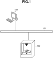
- Fig. 1 illustrates an example of a configuration of a system according to a first exemplary embodiment of the present invention.
- a personal computer (PC) 103 and a forming apparatus 102 are connected to each other via a network 101, such as a local area network (LAN).
- a network 101 such as a local area network (LAN).
- the PC 103 transmits forming data for forming a target object to the forming apparatus 102.
- the forming apparatus 102 receives the forming data and performs a forming process for forming a three-dimensional object.
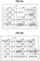
- Figs. 2A and 2B illustrate examples of hardware configurations of the apparatuses according to the present exemplary embodiment.
- Fig. 2A illustrates a configuration of an information processing apparatus, such as the PC 103.
- Fig. 2B illustrates a configuration of the forming apparatus 102.
- a central processing unit (CPU) 201 performs a process based on each code of an application program, a program for forming control according to the present exemplary embodiment, or the like stored in a read only memory (ROM) 203 or an external memory 211, and comprehensively controls each of devices connected to a system bus 212. Further, the CPU 201 opens registered various kinds of application windows based on a command issued with, for example, a not-illustrated mouse cursor on a display 209, and performs various kinds of data processing.
- ROM read only memory
- a random access memory (RAM) 202 functions as a main memory, a work area, and the like of the CPU 201.
- the ROM 203 is a read only memory that functions as an area for storing a basic input/output (I/O) program and the like.
- the ROM 203 or the external memory 211 stores, for example, an operating system (hereinafter referred to as an OS), which is a control program of the CPU 201. Further, the ROM 203 or the external memory 211 stores a file and other various kinds of data to be used in the process based on the above-described application program or the like.
- OS operating system
- the ROM 203 or the external memory 211 stores a file and other various kinds of data to be used in the process based on the above-described application program or the like.
- a network interface (I/F) 204 connects to the network 101 and carries out network communication.
- An input I/F 205 controls inputs from a keyboard 206 and a pointing device 207, such as a mouse.
- a display I/F 208 controls a display on the display 209.
- An external memory I/F 210 controls access to the external memory 211, such as a hard disk (HD).
- HD hard disk
- the external memory 211 stores a boot program, various kinds of applications, the program for the forming control according to the present exemplary embodiment, a user file, an editing file, and/or the like.
- the computer 103 operates with the CPU 201 executing the basic I/O program and the OS written in the ROM 203 or the external memory 211.
- the basic I/O program is written in the ROM 203, and the OS is written in the ROM 203 or the external memory 211.
- the OS is written from the ROM 203 or the external memory 211 into the RAM 202 by an initial program load function in the basic I/O program, and then an operation of the OS is started.
- a network I/F 251 connects to the network 101 and carries out network communication.
- the forming apparatus 102 may also include a Universal Serial Bus (USB) interface.
- the forming apparatus 102 will receive a forming instruction and the forming data corresponding to the target object via the network I/F 251 or the not-illustrated USB I/F.
- USB Universal Serial Bus
- a CPU 252 comprehensively controls each of devices connected to a system bus 265 based on an application program, a program for the forming control according to the present exemplary embodiment, or the like. Especially, the CPU 252 outputs, for example, a control signal for the object formation to a forming unit 264 via a controller 263.
- a control program is stored in a ROM 254, an external memory 262, or the like.
- the CPU 252 is configured to be able to perform a communication process with the computer 103 via the network I/F 251, and notify the computer 103 of information in the forming apparatus 102 and the like. Further, the CPU 252 performs a process based on, for example, the application program stored in the ROM 254 or the external memory 262.
- a RAM 253 functions as a main memory, a work area, and the like of the CPU 252, and is configured to be able to extent its own memory capacity by an optional RAM connected to a not-illustrated extension port.
- the RAM 253 is used as an area into which output information is developed, an area in which environmental data is stored, a nonvolatile random access memory (NVRAM), and/or the like.
- the ROM 254 or the external memory 262 stores the control program of the CPU 252, the application program, font data to be used when the above-described output information is generated, information to be used on the forming apparatus 102, and the like. Further, the ROM 254 or the external memory 262 temporarily stores an application when the application is installed into the forming apparatus 102.
- An operation unit I/F 255 is in charge of an interface with an operation unit 256, and outputs image data that should be displayed to the operation unit 256. Further, the operation unit I/F 255 also receives information input by the user via the operation unit 256.
- the operation unit 256 corresponds to, for example, an operation panel on which a switch for an operation, a light emitting diode (LED) indicator, and the like are provided.
- a printer I/F 257 outputs an image signal as output information to a printer 258 (a printer engine).
- a sensor I/F 259 receives a signal as input information from a sensor 260 (a temperature sensor, a vibration sensor, an object identification sensor, or the like). Examples of the sensor 260 further include a sensor that detects a remaining amount of a consumable material to be used in the formation in a material feeding unit set on the forming apparatus 102.
- the consumable material such as liquid and powder may be supplied according to a style of supplying it by detachably mounting a cartridge containing the consumable material onto the material feeding unit.
- the consumable material may be supplied according to a style of manually replenishing the consumable material from a special bottle or the like into the material feeding unit.
- An external memory I/F (a memory controller) 261 controls access to the external memory 262, such as an HD and an integrated circuit (IC) card.
- the forming apparatus 102 may include not only a single memory but also at least one or more memory or memories as the above-described external memory 261, and be configured to allow connections of a plurality of external memories storing an optional font card usable in addition to a built-in font or a program that interprets a printer control language belonging to a different language series. Further, the forming apparatus 102 may include a not-illustrated NVRAM, and be configured to store information about a printer mode setting set from the operation unit 256.
- the controller 263 causes the forming unit 264 to perform the forming process based on the received signal for the three-dimensional object formation.
- the forming unit 264 includes equipment for layering the material, a stage where the object is formed, a device functioning as an energy source for curing the material, and the like, although the included components vary depending on a forming method.
- the forming unit 264 is configured in a different manner according to the forming method, and specific examples thereof will be described below with reference to Figs. 3A-1, 3A-2, and 3B .
- examples of an optional device addable to the forming apparatus 102 include supplementary equipment that may be required according to the forming method, and a peripheral device that extends the functionality and mechanism of the three-dimensional (3D) printer, such as a camera and an IC card reader.
- examples of the supplementary equipment include a device required as a measure against powder in a case of the inkjet method, and a cleaning device required in a case of stereolithography (SLA).
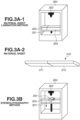
- Figs. 3A-1, 3A-2, and 3B illustrate examples of forming methods for carrying out "additive manufacturing" to which the present exemplary embodiment is applicable.
- Fig. 3A-1 illustrates a method for forming the three-dimensional object based on the material sheet lamination method.
- the forming unit 264 gradually forms an object 304 by additive manufacturing, by repeatedly layering a material sheet 310 on a stage 301 and radiating energy (light, heat, or the like) from an energy source 302.
- Fig. 3A-2 illustrates one material sheet 310.
- the material sheet 310 includes a structural material 312 containing the material and a support material 311.
- the structural material 312 is welded to structural material portions of the material sheets 310 stacked under and on itself by receiving the energy from the energy source 302. This leads to gradual completion of the additive manufacturing object 304.
- the support material 311 is not welded to the additive manufacturing object 304, and is being layered on the stage 301 as a support 303 of the additive manufacturing object 304.
- the support 303 is water-soluble, and can be removed by watering the support 303 portion when extracting the additive manufacturing object 304.
- Fig. 3B illustrates a method for additive manufacturing of the three-dimensional object based on the stereolithography method.
- the forming unit 264 gradually forms the object 304 by additive manufacturing, by repeatedly layering a material (ultraviolet-curable resin or the like) on the stage 301 and radiating energy (ultraviolet from a laser, or the like) from the energy source 302.
- a portion unexposed to the ultraviolet ends up remaining on the stage 301 without being cured.
- the uncured material serves as the support for the additive manufacturing object 304 as remaining there.
- the object 304 can be extracted alone by removing the uncured portion.
- the delayed join process proposed by the exemplary embodiments of the present invention can be realized by being adding coordinate information corresponding to the object to be additionally formed to coordinate information corresponding to the object being formed as a position to be irradiated with the energy.
- the present drawing is a conceptual drawing for illustrating the present exemplary embodiment, and each module is a module exemplarily depicted so as to serve as a performer of the process realized by the CPU 201 or the CPU 252 executing codes of the above-described program for the forming control.
- a reception unit 401 receives the instruction for the delayed join process and the forming data targeted for the delayed join process.
- the forming data includes, for example, a data file in the Standard Triangulated Language (STL) format that corresponds to three-dimensional model data.
- STL Standard Triangulated Language
- the present exemplary embodiment is applicable even when the forming data is data in another format ((the Wavefront Object (OBJ) format or the like) supportable by the PC 103 or the forming apparatus 102, which controls the three-dimensional object formation. Besides that, the present exemplary embodiment is also applicable even when the forming data is data in Additive Manufacturing File Format (AMF). Further, forming commands generated from the model data (data specifying a coordinate position targeted for the forming on each layer surface of the additive manufacturing object) may be used as the forming data.
- OBJ Wavefront Object
- a forming management unit 402 determines information about the object being currently formed by the forming apparatus 102, and whether the delayed join process can be performed.
- a device information management unit 403 manages performance information of the forming apparatus 102, especially, information including, for example, a size of an entire space where the formation can be carried out on the stage.
- a forming control unit 404 controls the forming instruction according to the forming method based on the forming data. More specifically, the forming control unit 404 instructs the forming unit 264 to form the three-dimensional object via the controller 263.
- a notification unit 405 issues notifications that convey messages indicating a start and completion of the formation, a failure, a cancellation of the delayed join process, and the like with use of the display 209 or the operation unit 256.
- the notification unit 405 can also notify an external apparatus of these messages via the network 101.
- the individual steps are performed by being divided between the PC 103 and the forming apparatus 102, like the PC 103 performing only steps involving a notification process, such as steps S505, S508, S510, and S512, which will be described below.
- a notification process such as steps S505, S508, S510, and S512, which will be described below.
- the PC 103 performs the notification process
- at least a program for realizing the configuration regarding the notification unit 405 is supposed to be stored and executed therein.
- the notification by the notification unit 405 is mainly assumed to be achieved by a display on the operation unit 256 of the forming apparatus 102 or the display 209 of the PC 103, but may be issued to the external apparatus in the network 101 with use of an electronic mail or the like.
- the reception unit 401 receives the instruction for the delayed join process and the forming data targeted for the delayed join process.
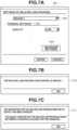
- the user specifies a forming apparatus to be set as a target where the delayed join process is performed from a pull-down menu 702 via a setting screen 701 illustrated in Fig. 7A .
- the forming apparatus 102 is configured to allow the user to select the forming apparatus currently carrying out the formation among a plurality of pre-registered forming apparatuses capable of performing the delayed join process.
- the user can further specify various kinds of parameters regarding the forming process as forming settings 703 on the setting screen 701. Further, the user can specify a forming setting specific to the selected forming apparatus on a different screen or the like by pressing an advanced setting button 704.
- an ENTER button is pressed on the setting screen 701
- the setting screen 701 is displayed on the operation unit 256 of the forming apparatus 102 or the display 209 of the PC 103.
- step S502 the forming management unit 402 identifies a forming position with respect to the object being currently formed.
- the position can be identified by acquiring the coordinate information on the stage of the forming unit 264 via the forming control unit 404.
- step S503 the forming management unit 402 calculates a free space where the formation can be carried out in addition to the object being currently formed on the stage of the forming apparatus 102.
- FIGs. 6A and 6B illustrate examples of the forming position in the delayed join process.
- a method for calculating the free space that is performed by the forming management unit 402 will be described with reference to Figs. 6A and 6B .
- Fig. 6A illustrates a first example of a forming pattern according to which the delayed join process is performed.
- a three-dimensional space 605 that would contain the entire additive manufacturing object when the object being formed is completed will be secured in advance on the stage, and the object targeted for the delayed join process will be formed within a space 606 other than the space 605 on the stage.
- the three-dimensional space 605 is a space that would contain the entire additive manufacturing object when the object being formed is completed. Then, an additive manufacturing object 603 is an already formed object at this point. An object 610 virtually indicates an object before the object is formed.
- Positional information 604 indicates the forming position of the object being currently formed that is being irradiated with the energy. The positional information 604 should include at least coordinate data indicating a height in a direction perpendicular to a horizontal surface of the stage 601 where the consumable material is layered.
- a three-dimensional space 606 is a space prepared above the stage 601 that does not overlap the portion where the three-dimensional space 605 is set up on the stage 601.
- a coordinate indicating a height of a bottom surface of the three-dimensional space 606 in the direction perpendicular to the horizontal surface of the stage 601 is set to a higher value than the coordinate indicating the height of the positional information 604.
- the setting of the value is determined according to, for example, a formation speed of the forming apparatus 102.
- the coordinate of the bottom surface of the three-dimensional space 606 in the height direction above the stage 601 is set to a value acquired by adding a predetermined value that allows a command to be additionally issued in time in step S507, which will be described below, to the coordinate of the positional information 604 in the height direction.
- the forming management unit 402 manages an area (a width and a depth) of the portion on the stage 601 where the three-dimensional space 605 is set up. Therefore, the forming management unit 402 can acquire a width, a depth, and a height 607 of the three-dimensional space 606 because of the determination of the coordinate indicating the height of the bottom surface of the three-dimensional space 606 in the direction perpendicular to the horizontal surface of the stage 601. In other words, the forming management unit 402 can calculate the free space for the delayed join process in step S503.
- a three-dimensional space 608 is a space on the stage 601 that is located below the three-dimensional space 606, and the space 608 is filled with the consumable material, which works as the support when the additive manufacturing object 603 is formed. More specifically, in the case of the material sheet lamination method, the three-dimensional space 608 works as the support 303 formed by the support material 311. Alternatively, in the case of the above-described stereolithography method, the three-dimensional space 608 is filled with the material uncured by the ultraviolet that works as the support. This means that, in the three-dimensional space 606, the object is formed above them working as the support.
- the delayed join process according to the forming pattern 1 illustrated in Fig. 6A leads to parallel formation of at least a part of each of the plurality of target objects from halfway through one forming process.
- the coordinate indicating the height of the bottom surface of the three-dimensional space 606 in the direction perpendicular to the horizontal surface of the stage 601 matches a top surface of the three-dimensional space 605, whereby the height 607 of the three-dimensional space 606 can be acquired as a difference from the height 602 of the entire space.
- the area (the width and the depth) of the three-dimensional space 606 matches the three-dimensional space 605.
- the forming management unit 402 can calculate the free space for the delayed join process in step S503.
- the delayed join process according to the forming pattern 2 illustrated in Fig. 6B leads to sequential formation of the plurality of target objects during one forming process.
- the forming management unit 402 determines whether the corresponding object can be contained in the free space available for the additional formation that has been calculated in step S503, and will determine that the delayed join process can be performed only if the object can be contained. Further, as another determination, the forming management unit 402 determines whether the delayed join process can be performed by checking whether the forming settings set via the setting screen 701 do not conflict with the forming settings of the object being currently formed. For example, if a type of the material or a thickness of the stacked layer (a layer pitch) is not the same between the respective forming settings, the forming management unit 402 determines that the delayed join process cannot be performed. If there is not such a setting as the one causing a conflict, the forming management unit 402 can determine that the delayed join process can be performed.
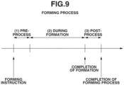
- the user is supposed to perform a post-process such as the work of extracting the object and the removal of the support according to the completion notification.
- Fig. 8 illustrates a forming setting screen provided by the forming management unit 402 according to the second exemplary embodiment.
- a setting screen 801 is different from the screen illustrated in Fig. 7A and is a setting screen for issuing the forming instruction to a forming apparatus that is not carrying out the formation.
- the setting screen 801 is displayed on the operation unit 256 of the forming apparatus 102 or the display 209 of the PC 103.
- the user can select the forming apparatus with which the user wants to carry out the formation with use of a pull-down menu 802. Further, the user can configure the various kinds of forming settings on the setting screen 801, similarly to Figs. 7A, 7B, and 7C .
- a determination process based on the setting specified in the menu 806 is added in step S504 illustrated in Fig. 5 in addition to the first exemplary embodiment.
- the second exemplary embodiment can also include control of adjusting, for example, the orientation of the object so as to minimize the height of the targeted object in consideration of the forming pattern described with reference to Fig. 6B .
- the delayed join process proposed by the exemplary embodiments of the present invention with respect to a forming method that does not move the stage where the object is set up but moves a head or the like for layering the material in the direction perpendicular to the horizontal surface of the stage.
- configuring the apparatus to also move the stage divided in advance in the perpendicular direction at the time of the delayed join process allows an additional object to be formed by the delayed join process on the stage.
- control such as also forming the support material in advance on the stage where no object is formed in preparation for the delayed join process allows an additional object to be formed by the delayed join process on the support material.
- Embodiment(s) of the present invention can also be realized by a computer of a system or apparatus that reads out and executes computer executable instructions (e.g., one or more programming codes) recorded on a storage medium (which may also be referred to more fully as a 'non-transitory computer-readable storage medium') to perform the functions of one or more of the above-described embodiment(s) and/or that includes one or more circuits (e.g., application specific integrated circuit (ASIC)) for performing the functions of one or more of the above-described embodiment(s), and by a method performed by the computer of the system or apparatus by, for example, reading out and executing the computer executable instructions from the storage medium to perform the functions of one or more of the above-described embodiment(s) and/or controlling the one or more circuits to perform the functions of one or more of the above-described embodiment (s) .
- computer executable instructions e.g., one or more programming codes
- a storage medium which may also be referred to
Landscapes
- Engineering & Computer Science (AREA)
- Chemical & Material Sciences (AREA)
- Materials Engineering (AREA)
- Manufacturing & Machinery (AREA)
- Physics & Mathematics (AREA)
- Mechanical Engineering (AREA)
- Optics & Photonics (AREA)
- General Physics & Mathematics (AREA)
- Automation & Control Theory (AREA)
- Human Computer Interaction (AREA)
- General Engineering & Computer Science (AREA)
Applications Claiming Priority (2)
| Application Number | Priority Date | Filing Date | Title |
|---|---|---|---|
| JP2016069176A JP6758876B2 (ja) | 2016-03-30 | 2016-03-30 | 造形制御装置、その方法及びプログラム |
| EP17163396.9A EP3239794B1 (en) | 2016-03-30 | 2017-03-28 | Forming control apparatus, and method and program therefor |
Related Parent Applications (2)
| Application Number | Title | Priority Date | Filing Date |
|---|---|---|---|
| EP17163396.9A Division EP3239794B1 (en) | 2016-03-30 | 2017-03-28 | Forming control apparatus, and method and program therefor |
| EP17163396.9A Division-Into EP3239794B1 (en) | 2016-03-30 | 2017-03-28 | Forming control apparatus, and method and program therefor |
Publications (2)
| Publication Number | Publication Date |
|---|---|
| EP3761130A1 EP3761130A1 (en) | 2021-01-06 |
| EP3761130B1 true EP3761130B1 (en) | 2023-05-10 |
Family
ID=58672279
Family Applications (2)
| Application Number | Title | Priority Date | Filing Date |
|---|---|---|---|
| EP20187087.0A Active EP3761130B1 (en) | 2016-03-30 | 2017-03-28 | Forming control apparatus, and method and program therefor |
| EP17163396.9A Not-in-force EP3239794B1 (en) | 2016-03-30 | 2017-03-28 | Forming control apparatus, and method and program therefor |
Family Applications After (1)
| Application Number | Title | Priority Date | Filing Date |
|---|---|---|---|
| EP17163396.9A Not-in-force EP3239794B1 (en) | 2016-03-30 | 2017-03-28 | Forming control apparatus, and method and program therefor |
Country Status (5)
| Country | Link |
|---|---|
| US (3) | US10754311B2 (enExample) |
| EP (2) | EP3761130B1 (enExample) |
| JP (1) | JP6758876B2 (enExample) |
| KR (1) | KR102202175B1 (enExample) |
| CN (1) | CN107263853B (enExample) |
Families Citing this family (4)
| Publication number | Priority date | Publication date | Assignee | Title |
|---|---|---|---|---|
| US12064922B2 (en) | 2017-12-05 | 2024-08-20 | Fisher Controls International Llc | Optimally positioning objects for additive manufacturing and post-processing |
| CN109910293A (zh) * | 2017-12-13 | 2019-06-21 | 尚远望 | 一种基于3d打印技术的机械零件成型方法 |
| WO2020160214A1 (en) * | 2019-02-01 | 2020-08-06 | Digital Alloys Incorporated | Systems and methods for three-dimensional printing |
| JP2022084528A (ja) * | 2020-11-26 | 2022-06-07 | 株式会社リコー | 管理システム及び管理装置 |
Family Cites Families (19)
| Publication number | Priority date | Publication date | Assignee | Title |
|---|---|---|---|---|
| JPH09216291A (ja) * | 1996-02-09 | 1997-08-19 | Ricoh Co Ltd | 三次元物体形成方法、三次元物体形成装置、及び三次元物体 |
| US6022207A (en) * | 1998-01-26 | 2000-02-08 | Stratasys, Inc. | Rapid prototyping system with filament supply spool monitoring |
| US6490496B1 (en) | 1999-02-25 | 2002-12-03 | 3D Systems, Inc. | Method, apparatus, and article of manufacture for a control system in a selective deposition modeling system |
| US7290221B2 (en) | 2003-04-16 | 2007-10-30 | Hewlett-Packard Development Company, L.P. | User interface, method and apparatus for providing three-dimensional object fabrication status |
| US6983188B2 (en) * | 2004-04-16 | 2006-01-03 | Hewlett-Packard Development Company, L.P. | Scheduling system |
| WO2008107866A1 (en) * | 2007-03-07 | 2008-09-12 | Objet Geometries Ltd. | Rapid production apparatus |
| JP5615667B2 (ja) | 2010-11-01 | 2014-10-29 | 株式会社キーエンス | 三次元造形装置用の設定データ作成装置、三次元造形装置用の設定データ作成方法及び三次元造形装置用の設定データ作成プログラム並びにコンピュータで読み取り可能な記録媒体 |
| EP2758837B1 (en) * | 2011-09-23 | 2020-05-27 | Stratasys, Inc. | Layer transfusion for additive manufacturing |
| WO2015022572A2 (en) * | 2013-08-13 | 2015-02-19 | Fabulonia Ou | Optimized virtual 3d printing build tray allocation |
| US10195778B2 (en) * | 2013-10-15 | 2019-02-05 | Wolf & Associates, Inc. | Three-dimensional printer systems and methods |
| JP6366252B2 (ja) * | 2013-11-01 | 2018-08-01 | キヤノン株式会社 | データ処理装置、データ処理装置の制御方法及びプログラム |
| NL2012198C2 (nl) | 2014-02-04 | 2015-08-06 | Leapfrog B V | Inrichting voor het door middel van 3d-extrusie vormen van een werkstuk. |
| CN112549529B (zh) * | 2014-07-13 | 2022-11-29 | 斯特拉塔西斯公司 | 用于三维打印的系统及制造三维物体的方法 |
| KR102223280B1 (ko) * | 2014-07-16 | 2021-03-05 | 엘지전자 주식회사 | 이동 단말기 및 이의 제어방법 |
| KR101944737B1 (ko) | 2014-08-14 | 2019-02-01 | 삼성에스디에스 주식회사 | 3차원 프린팅 제어 장치 및 방법 |
| JP6383488B2 (ja) * | 2014-08-29 | 2018-08-29 | ヒューレット−パッカード デベロップメント カンパニー エル.ピー.Hewlett‐Packard Development Company, L.P. | 3次元オブジェクトの生成 |
| US20160274572A1 (en) * | 2015-03-19 | 2016-09-22 | Michael G. Littrell | Three Dimensional (3D) Printing and CAD File Quoting System |
| US10322470B2 (en) * | 2015-04-06 | 2019-06-18 | The Boeing Company | Deposition head for additive manufacturing |
| US10696038B2 (en) * | 2015-12-16 | 2020-06-30 | Stratasys, Inc. | Multi-user access to fabrication resources |
-
2016
- 2016-03-30 JP JP2016069176A patent/JP6758876B2/ja active Active
-
2017
- 2017-03-17 US US15/462,235 patent/US10754311B2/en active Active
- 2017-03-23 KR KR1020170036606A patent/KR102202175B1/ko active Active
- 2017-03-24 CN CN201710180821.1A patent/CN107263853B/zh active Active
- 2017-03-28 EP EP20187087.0A patent/EP3761130B1/en active Active
- 2017-03-28 EP EP17163396.9A patent/EP3239794B1/en not_active Not-in-force
-
2020
- 2020-07-17 US US16/932,406 patent/US11573543B2/en active Active
-
2023
- 2023-01-04 US US18/149,871 patent/US12311608B2/en active Active
Also Published As
| Publication number | Publication date |
|---|---|
| KR102202175B1 (ko) | 2021-01-13 |
| KR20170113197A (ko) | 2017-10-12 |
| US20230141468A1 (en) | 2023-05-11 |
| CN107263853A (zh) | 2017-10-20 |
| EP3761130A1 (en) | 2021-01-06 |
| US11573543B2 (en) | 2023-02-07 |
| EP3239794B1 (en) | 2020-09-02 |
| JP2017177575A (ja) | 2017-10-05 |
| US12311608B2 (en) | 2025-05-27 |
| US20200348634A1 (en) | 2020-11-05 |
| EP3239794A1 (en) | 2017-11-01 |
| US10754311B2 (en) | 2020-08-25 |
| US20170282458A1 (en) | 2017-10-05 |
| CN107263853B (zh) | 2020-04-10 |
| JP6758876B2 (ja) | 2020-09-23 |
Similar Documents
| Publication | Publication Date | Title |
|---|---|---|
| US12311608B2 (en) | Forming control apparatus, and method and storage medium therefor | |
| US10775769B2 (en) | Information processing apparatus, control method, and storage medium | |
| JP6366252B2 (ja) | データ処理装置、データ処理装置の制御方法及びプログラム | |
| US20170266884A1 (en) | Information processing apparatus, modeling system, and information processing method | |
| JP6711394B2 (ja) | 情報処理装置、プログラム、情報処理方法、造形システム | |
| JP2017159634A (ja) | 情報処理装置、制御方法、及びプログラム | |
| US10394497B2 (en) | Relay apparatus that registers user information included in a forming request in a group that includes the account of the relay apparatus, control method, and storage medium | |
| JP6827741B2 (ja) | 情報処理装置、制御方法、およびプログラム | |
| US10732610B2 (en) | Information processing terminal, management system, and control method | |
| JP6593035B2 (ja) | 制御システム、情報処理装置、造形システムおよびプログラム | |
| JP6992132B2 (ja) | 造形制御装置、その方法及びプログラム | |
| US10744706B2 (en) | Forming control apparatus, control method, and storage medium | |
| JP2017039252A (ja) | 制御システム、情報処理装置、造形システムおよびプログラム | |
| JP6914683B2 (ja) | 中継装置、制御方法、およびプログラム | |
| KR20200075150A (ko) | 표면 프린트 타입의 3d 프린터 | |
| JP6524719B2 (ja) | 情報処理装置、プログラムおよび記録媒体 | |
| JP2018043478A (ja) | 造形制御装置、その方法及びプログラム |
Legal Events
| Date | Code | Title | Description |
|---|---|---|---|
| PUAI | Public reference made under article 153(3) epc to a published international application that has entered the european phase |
Free format text: ORIGINAL CODE: 0009012 |
|
| STAA | Information on the status of an ep patent application or granted ep patent |
Free format text: STATUS: THE APPLICATION HAS BEEN PUBLISHED |
|
| AC | Divisional application: reference to earlier application |
Ref document number: 3239794 Country of ref document: EP Kind code of ref document: P |
|
| AK | Designated contracting states |
Kind code of ref document: A1 Designated state(s): AL AT BE BG CH CY CZ DE DK EE ES FI FR GB GR HR HU IE IS IT LI LT LU LV MC MK MT NL NO PL PT RO RS SE SI SK SM TR |
|
| STAA | Information on the status of an ep patent application or granted ep patent |
Free format text: STATUS: REQUEST FOR EXAMINATION WAS MADE |
|
| 17P | Request for examination filed |
Effective date: 20210706 |
|
| RBV | Designated contracting states (corrected) |
Designated state(s): AL AT BE BG CH CY CZ DE DK EE ES FI FR GB GR HR HU IE IS IT LI LT LU LV MC MK MT NL NO PL PT RO RS SE SI SK SM TR |
|
| STAA | Information on the status of an ep patent application or granted ep patent |
Free format text: STATUS: EXAMINATION IS IN PROGRESS |
|
| 17Q | First examination report despatched |
Effective date: 20220104 |
|
| GRAP | Despatch of communication of intention to grant a patent |
Free format text: ORIGINAL CODE: EPIDOSNIGR1 |
|
| STAA | Information on the status of an ep patent application or granted ep patent |
Free format text: STATUS: GRANT OF PATENT IS INTENDED |
|
| INTG | Intention to grant announced |
Effective date: 20221206 |
|
| GRAS | Grant fee paid |
Free format text: ORIGINAL CODE: EPIDOSNIGR3 |
|
| GRAA | (expected) grant |
Free format text: ORIGINAL CODE: 0009210 |
|
| STAA | Information on the status of an ep patent application or granted ep patent |
Free format text: STATUS: THE PATENT HAS BEEN GRANTED |
|
| AC | Divisional application: reference to earlier application |
Ref document number: 3239794 Country of ref document: EP Kind code of ref document: P |
|
| AK | Designated contracting states |
Kind code of ref document: B1 Designated state(s): AL AT BE BG CH CY CZ DE DK EE ES FI FR GB GR HR HU IE IS IT LI LT LU LV MC MK MT NL NO PL PT RO RS SE SI SK SM TR |
|
| REG | Reference to a national code |
Ref country code: GB Ref legal event code: FG4D |
|
| REG | Reference to a national code |
Ref country code: AT Ref legal event code: REF Ref document number: 1567304 Country of ref document: AT Kind code of ref document: T Effective date: 20230515 Ref country code: CH Ref legal event code: EP |
|
| REG | Reference to a national code |
Ref country code: DE Ref legal event code: R096 Ref document number: 602017068802 Country of ref document: DE |
|
| REG | Reference to a national code |
Ref country code: IE Ref legal event code: FG4D |
|
| REG | Reference to a national code |
Ref country code: LT Ref legal event code: MG9D |
|
| REG | Reference to a national code |
Ref country code: NL Ref legal event code: MP Effective date: 20230510 |
|
| REG | Reference to a national code |
Ref country code: AT Ref legal event code: MK05 Ref document number: 1567304 Country of ref document: AT Kind code of ref document: T Effective date: 20230510 |
|
| PG25 | Lapsed in a contracting state [announced via postgrant information from national office to epo] |
Ref country code: SE Free format text: LAPSE BECAUSE OF FAILURE TO SUBMIT A TRANSLATION OF THE DESCRIPTION OR TO PAY THE FEE WITHIN THE PRESCRIBED TIME-LIMIT Effective date: 20230510 Ref country code: PT Free format text: LAPSE BECAUSE OF FAILURE TO SUBMIT A TRANSLATION OF THE DESCRIPTION OR TO PAY THE FEE WITHIN THE PRESCRIBED TIME-LIMIT Effective date: 20230911 Ref country code: NO Free format text: LAPSE BECAUSE OF FAILURE TO SUBMIT A TRANSLATION OF THE DESCRIPTION OR TO PAY THE FEE WITHIN THE PRESCRIBED TIME-LIMIT Effective date: 20230810 Ref country code: NL Free format text: LAPSE BECAUSE OF FAILURE TO SUBMIT A TRANSLATION OF THE DESCRIPTION OR TO PAY THE FEE WITHIN THE PRESCRIBED TIME-LIMIT Effective date: 20230510 Ref country code: ES Free format text: LAPSE BECAUSE OF FAILURE TO SUBMIT A TRANSLATION OF THE DESCRIPTION OR TO PAY THE FEE WITHIN THE PRESCRIBED TIME-LIMIT Effective date: 20230510 Ref country code: AT Free format text: LAPSE BECAUSE OF FAILURE TO SUBMIT A TRANSLATION OF THE DESCRIPTION OR TO PAY THE FEE WITHIN THE PRESCRIBED TIME-LIMIT Effective date: 20230510 |
|
| PG25 | Lapsed in a contracting state [announced via postgrant information from national office to epo] |
Ref country code: RS Free format text: LAPSE BECAUSE OF FAILURE TO SUBMIT A TRANSLATION OF THE DESCRIPTION OR TO PAY THE FEE WITHIN THE PRESCRIBED TIME-LIMIT Effective date: 20230510 Ref country code: PL Free format text: LAPSE BECAUSE OF FAILURE TO SUBMIT A TRANSLATION OF THE DESCRIPTION OR TO PAY THE FEE WITHIN THE PRESCRIBED TIME-LIMIT Effective date: 20230510 Ref country code: LV Free format text: LAPSE BECAUSE OF FAILURE TO SUBMIT A TRANSLATION OF THE DESCRIPTION OR TO PAY THE FEE WITHIN THE PRESCRIBED TIME-LIMIT Effective date: 20230510 Ref country code: LT Free format text: LAPSE BECAUSE OF FAILURE TO SUBMIT A TRANSLATION OF THE DESCRIPTION OR TO PAY THE FEE WITHIN THE PRESCRIBED TIME-LIMIT Effective date: 20230510 Ref country code: IS Free format text: LAPSE BECAUSE OF FAILURE TO SUBMIT A TRANSLATION OF THE DESCRIPTION OR TO PAY THE FEE WITHIN THE PRESCRIBED TIME-LIMIT Effective date: 20230910 Ref country code: HR Free format text: LAPSE BECAUSE OF FAILURE TO SUBMIT A TRANSLATION OF THE DESCRIPTION OR TO PAY THE FEE WITHIN THE PRESCRIBED TIME-LIMIT Effective date: 20230510 Ref country code: GR Free format text: LAPSE BECAUSE OF FAILURE TO SUBMIT A TRANSLATION OF THE DESCRIPTION OR TO PAY THE FEE WITHIN THE PRESCRIBED TIME-LIMIT Effective date: 20230811 |
|
| PG25 | Lapsed in a contracting state [announced via postgrant information from national office to epo] |
Ref country code: FI Free format text: LAPSE BECAUSE OF FAILURE TO SUBMIT A TRANSLATION OF THE DESCRIPTION OR TO PAY THE FEE WITHIN THE PRESCRIBED TIME-LIMIT Effective date: 20230510 |
|
| PG25 | Lapsed in a contracting state [announced via postgrant information from national office to epo] |
Ref country code: SK Free format text: LAPSE BECAUSE OF FAILURE TO SUBMIT A TRANSLATION OF THE DESCRIPTION OR TO PAY THE FEE WITHIN THE PRESCRIBED TIME-LIMIT Effective date: 20230510 |
|
| PG25 | Lapsed in a contracting state [announced via postgrant information from national office to epo] |
Ref country code: SM Free format text: LAPSE BECAUSE OF FAILURE TO SUBMIT A TRANSLATION OF THE DESCRIPTION OR TO PAY THE FEE WITHIN THE PRESCRIBED TIME-LIMIT Effective date: 20230510 Ref country code: SK Free format text: LAPSE BECAUSE OF FAILURE TO SUBMIT A TRANSLATION OF THE DESCRIPTION OR TO PAY THE FEE WITHIN THE PRESCRIBED TIME-LIMIT Effective date: 20230510 Ref country code: RO Free format text: LAPSE BECAUSE OF FAILURE TO SUBMIT A TRANSLATION OF THE DESCRIPTION OR TO PAY THE FEE WITHIN THE PRESCRIBED TIME-LIMIT Effective date: 20230510 Ref country code: EE Free format text: LAPSE BECAUSE OF FAILURE TO SUBMIT A TRANSLATION OF THE DESCRIPTION OR TO PAY THE FEE WITHIN THE PRESCRIBED TIME-LIMIT Effective date: 20230510 Ref country code: DK Free format text: LAPSE BECAUSE OF FAILURE TO SUBMIT A TRANSLATION OF THE DESCRIPTION OR TO PAY THE FEE WITHIN THE PRESCRIBED TIME-LIMIT Effective date: 20230510 Ref country code: CZ Free format text: LAPSE BECAUSE OF FAILURE TO SUBMIT A TRANSLATION OF THE DESCRIPTION OR TO PAY THE FEE WITHIN THE PRESCRIBED TIME-LIMIT Effective date: 20230510 |
|
| REG | Reference to a national code |
Ref country code: DE Ref legal event code: R097 Ref document number: 602017068802 Country of ref document: DE |
|
| PLBE | No opposition filed within time limit |
Free format text: ORIGINAL CODE: 0009261 |
|
| STAA | Information on the status of an ep patent application or granted ep patent |
Free format text: STATUS: NO OPPOSITION FILED WITHIN TIME LIMIT |
|
| 26N | No opposition filed |
Effective date: 20240213 |
|
| PG25 | Lapsed in a contracting state [announced via postgrant information from national office to epo] |
Ref country code: SI Free format text: LAPSE BECAUSE OF FAILURE TO SUBMIT A TRANSLATION OF THE DESCRIPTION OR TO PAY THE FEE WITHIN THE PRESCRIBED TIME-LIMIT Effective date: 20230510 |
|
| PG25 | Lapsed in a contracting state [announced via postgrant information from national office to epo] |
Ref country code: SI Free format text: LAPSE BECAUSE OF FAILURE TO SUBMIT A TRANSLATION OF THE DESCRIPTION OR TO PAY THE FEE WITHIN THE PRESCRIBED TIME-LIMIT Effective date: 20230510 Ref country code: IT Free format text: LAPSE BECAUSE OF FAILURE TO SUBMIT A TRANSLATION OF THE DESCRIPTION OR TO PAY THE FEE WITHIN THE PRESCRIBED TIME-LIMIT Effective date: 20230510 |
|
| REG | Reference to a national code |
Ref country code: CH Ref legal event code: PL |
|
| PG25 | Lapsed in a contracting state [announced via postgrant information from national office to epo] |
Ref country code: BG Free format text: LAPSE BECAUSE OF FAILURE TO SUBMIT A TRANSLATION OF THE DESCRIPTION OR TO PAY THE FEE WITHIN THE PRESCRIBED TIME-LIMIT Effective date: 20230510 |
|
| PG25 | Lapsed in a contracting state [announced via postgrant information from national office to epo] |
Ref country code: LU Free format text: LAPSE BECAUSE OF NON-PAYMENT OF DUE FEES Effective date: 20240328 |
|
| PG25 | Lapsed in a contracting state [announced via postgrant information from national office to epo] |
Ref country code: MC Free format text: LAPSE BECAUSE OF FAILURE TO SUBMIT A TRANSLATION OF THE DESCRIPTION OR TO PAY THE FEE WITHIN THE PRESCRIBED TIME-LIMIT Effective date: 20230510 |
|
| PG25 | Lapsed in a contracting state [announced via postgrant information from national office to epo] |
Ref country code: MC Free format text: LAPSE BECAUSE OF FAILURE TO SUBMIT A TRANSLATION OF THE DESCRIPTION OR TO PAY THE FEE WITHIN THE PRESCRIBED TIME-LIMIT Effective date: 20230510 Ref country code: LU Free format text: LAPSE BECAUSE OF NON-PAYMENT OF DUE FEES Effective date: 20240328 Ref country code: BG Free format text: LAPSE BECAUSE OF FAILURE TO SUBMIT A TRANSLATION OF THE DESCRIPTION OR TO PAY THE FEE WITHIN THE PRESCRIBED TIME-LIMIT Effective date: 20230510 |
|
| REG | Reference to a national code |
Ref country code: BE Ref legal event code: MM Effective date: 20240331 |
|
| PG25 | Lapsed in a contracting state [announced via postgrant information from national office to epo] |
Ref country code: BE Free format text: LAPSE BECAUSE OF NON-PAYMENT OF DUE FEES Effective date: 20240331 |
|
| PG25 | Lapsed in a contracting state [announced via postgrant information from national office to epo] |
Ref country code: IE Free format text: LAPSE BECAUSE OF NON-PAYMENT OF DUE FEES Effective date: 20240328 |
|
| PG25 | Lapsed in a contracting state [announced via postgrant information from national office to epo] |
Ref country code: IE Free format text: LAPSE BECAUSE OF NON-PAYMENT OF DUE FEES Effective date: 20240328 Ref country code: BE Free format text: LAPSE BECAUSE OF NON-PAYMENT OF DUE FEES Effective date: 20240331 Ref country code: CH Free format text: LAPSE BECAUSE OF NON-PAYMENT OF DUE FEES Effective date: 20240331 |
|
| PG25 | Lapsed in a contracting state [announced via postgrant information from national office to epo] |
Ref country code: CY Free format text: LAPSE BECAUSE OF FAILURE TO SUBMIT A TRANSLATION OF THE DESCRIPTION OR TO PAY THE FEE WITHIN THE PRESCRIBED TIME-LIMIT; INVALID AB INITIO Effective date: 20170328 |
|
| PG25 | Lapsed in a contracting state [announced via postgrant information from national office to epo] |
Ref country code: HU Free format text: LAPSE BECAUSE OF FAILURE TO SUBMIT A TRANSLATION OF THE DESCRIPTION OR TO PAY THE FEE WITHIN THE PRESCRIBED TIME-LIMIT; INVALID AB INITIO Effective date: 20170328 |
|
| PG25 | Lapsed in a contracting state [announced via postgrant information from national office to epo] |
Ref country code: TR Free format text: LAPSE BECAUSE OF FAILURE TO SUBMIT A TRANSLATION OF THE DESCRIPTION OR TO PAY THE FEE WITHIN THE PRESCRIBED TIME-LIMIT Effective date: 20230510 |
|
| PGFP | Annual fee paid to national office [announced via postgrant information from national office to epo] |
Ref country code: GB Payment date: 20260220 Year of fee payment: 10 |
|
| PGFP | Annual fee paid to national office [announced via postgrant information from national office to epo] |
Ref country code: DE Payment date: 20260219 Year of fee payment: 10 |
|
| PGFP | Annual fee paid to national office [announced via postgrant information from national office to epo] |
Ref country code: FR Payment date: 20260219 Year of fee payment: 10 |