EP3761087A1 - Multicore fiber and manufacturing method therefor, and optical transmission system and optical transmission method - Google Patents
Multicore fiber and manufacturing method therefor, and optical transmission system and optical transmission method Download PDFInfo
- Publication number
- EP3761087A1 EP3761087A1 EP19760218.8A EP19760218A EP3761087A1 EP 3761087 A1 EP3761087 A1 EP 3761087A1 EP 19760218 A EP19760218 A EP 19760218A EP 3761087 A1 EP3761087 A1 EP 3761087A1
- Authority
- EP
- European Patent Office
- Prior art keywords
- core
- standard
- cores
- optical transmission
- optical
- Prior art date
- Legal status (The legal status is an assumption and is not a legal conclusion. Google has not performed a legal analysis and makes no representation as to the accuracy of the status listed.)
- Pending
Links
- 230000003287 optical effect Effects 0.000 title claims abstract description 115
- 239000000835 fiber Substances 0.000 title claims abstract description 103
- 230000005540 biological transmission Effects 0.000 title claims abstract description 82
- 238000004519 manufacturing process Methods 0.000 title claims abstract description 21
- 238000000034 method Methods 0.000 title claims abstract description 18
- 238000005253 cladding Methods 0.000 claims abstract description 73
- 239000013307 optical fiber Substances 0.000 claims description 20
- 239000006185 dispersion Substances 0.000 claims description 14
- 239000011521 glass Substances 0.000 claims description 8
- 230000002457 bidirectional effect Effects 0.000 claims description 7
- 238000010438 heat treatment Methods 0.000 claims description 5
- 230000000644 propagated effect Effects 0.000 claims description 4
- 238000005553 drilling Methods 0.000 claims description 3
- 238000010586 diagram Methods 0.000 description 14
- VYPSYNLAJGMNEJ-UHFFFAOYSA-N Silicium dioxide Chemical compound O=[Si]=O VYPSYNLAJGMNEJ-UHFFFAOYSA-N 0.000 description 8
- 239000011295 pitch Substances 0.000 description 7
- 230000000694 effects Effects 0.000 description 5
- 238000005094 computer simulation Methods 0.000 description 4
- 230000003247 decreasing effect Effects 0.000 description 4
- 235000012239 silicon dioxide Nutrition 0.000 description 4
- 239000002019 doping agent Substances 0.000 description 3
- 239000000470 constituent Substances 0.000 description 2
- RKTYLMNFRDHKIL-UHFFFAOYSA-N copper;5,10,15,20-tetraphenylporphyrin-22,24-diide Chemical compound [Cu+2].C1=CC(C(=C2C=CC([N-]2)=C(C=2C=CC=CC=2)C=2C=CC(N=2)=C(C=2C=CC=CC=2)C2=CC=C3[N-]2)C=2C=CC=CC=2)=NC1=C3C1=CC=CC=C1 RKTYLMNFRDHKIL-UHFFFAOYSA-N 0.000 description 2
- 239000000284 extract Substances 0.000 description 2
- 239000003550 marker Substances 0.000 description 2
- 239000000463 material Substances 0.000 description 2
- 238000012856 packing Methods 0.000 description 2
- 230000002093 peripheral effect Effects 0.000 description 2
- 238000002360 preparation method Methods 0.000 description 2
- 101150034533 ATIC gene Proteins 0.000 description 1
- VYZAMTAEIAYCRO-UHFFFAOYSA-N Chromium Chemical compound [Cr] VYZAMTAEIAYCRO-UHFFFAOYSA-N 0.000 description 1
- PXGOKWXKJXAPGV-UHFFFAOYSA-N Fluorine Chemical compound FF PXGOKWXKJXAPGV-UHFFFAOYSA-N 0.000 description 1
- 230000007423 decrease Effects 0.000 description 1
- 230000008021 deposition Effects 0.000 description 1
- 238000013461 design Methods 0.000 description 1
- 229910052731 fluorine Inorganic materials 0.000 description 1
- 239000011737 fluorine Substances 0.000 description 1
- 229910052732 germanium Inorganic materials 0.000 description 1
- GNPVGFCGXDBREM-UHFFFAOYSA-N germanium atom Chemical compound [Ge] GNPVGFCGXDBREM-UHFFFAOYSA-N 0.000 description 1
- 238000000691 measurement method Methods 0.000 description 1
- 230000004048 modification Effects 0.000 description 1
- 238000012986 modification Methods 0.000 description 1
- 108091008695 photoreceptors Proteins 0.000 description 1
- 239000004065 semiconductor Substances 0.000 description 1
- 238000007740 vapor deposition Methods 0.000 description 1
Images




Classifications
-
- C—CHEMISTRY; METALLURGY
- C03—GLASS; MINERAL OR SLAG WOOL
- C03B—MANUFACTURE, SHAPING, OR SUPPLEMENTARY PROCESSES
- C03B37/00—Manufacture or treatment of flakes, fibres, or filaments from softened glass, minerals, or slags
- C03B37/01—Manufacture of glass fibres or filaments
- C03B37/012—Manufacture of preforms for drawing fibres or filaments
- C03B37/01205—Manufacture of preforms for drawing fibres or filaments starting from tubes, rods, fibres or filaments
- C03B37/01225—Means for changing or stabilising the shape, e.g. diameter, of tubes or rods in general, e.g. collapsing
- C03B37/01228—Removal of preform material
- C03B37/01231—Removal of preform material to form a longitudinal hole, e.g. by drilling
-
- C—CHEMISTRY; METALLURGY
- C03—GLASS; MINERAL OR SLAG WOOL
- C03B—MANUFACTURE, SHAPING, OR SUPPLEMENTARY PROCESSES
- C03B37/00—Manufacture or treatment of flakes, fibres, or filaments from softened glass, minerals, or slags
- C03B37/01—Manufacture of glass fibres or filaments
- C03B37/012—Manufacture of preforms for drawing fibres or filaments
- C03B37/01205—Manufacture of preforms for drawing fibres or filaments starting from tubes, rods, fibres or filaments
- C03B37/01211—Manufacture of preforms for drawing fibres or filaments starting from tubes, rods, fibres or filaments by inserting one or more rods or tubes into a tube
- C03B37/01214—Manufacture of preforms for drawing fibres or filaments starting from tubes, rods, fibres or filaments by inserting one or more rods or tubes into a tube for making preforms of multifibres, fibre bundles other than multiple core preforms
-
- C—CHEMISTRY; METALLURGY
- C03—GLASS; MINERAL OR SLAG WOOL
- C03B—MANUFACTURE, SHAPING, OR SUPPLEMENTARY PROCESSES
- C03B37/00—Manufacture or treatment of flakes, fibres, or filaments from softened glass, minerals, or slags
- C03B37/01—Manufacture of glass fibres or filaments
- C03B37/012—Manufacture of preforms for drawing fibres or filaments
- C03B37/01205—Manufacture of preforms for drawing fibres or filaments starting from tubes, rods, fibres or filaments
- C03B37/01211—Manufacture of preforms for drawing fibres or filaments starting from tubes, rods, fibres or filaments by inserting one or more rods or tubes into a tube
- C03B37/01222—Manufacture of preforms for drawing fibres or filaments starting from tubes, rods, fibres or filaments by inserting one or more rods or tubes into a tube for making preforms of multiple core optical fibres
-
- C—CHEMISTRY; METALLURGY
- C03—GLASS; MINERAL OR SLAG WOOL
- C03B—MANUFACTURE, SHAPING, OR SUPPLEMENTARY PROCESSES
- C03B37/00—Manufacture or treatment of flakes, fibres, or filaments from softened glass, minerals, or slags
- C03B37/01—Manufacture of glass fibres or filaments
- C03B37/02—Manufacture of glass fibres or filaments by drawing or extruding, e.g. direct drawing of molten glass from nozzles; Cooling fins therefor
- C03B37/025—Manufacture of glass fibres or filaments by drawing or extruding, e.g. direct drawing of molten glass from nozzles; Cooling fins therefor from reheated softened tubes, rods, fibres or filaments, e.g. drawing fibres from preforms
- C03B37/027—Fibres composed of different sorts of glass, e.g. glass optical fibres
-
- G—PHYSICS
- G02—OPTICS
- G02B—OPTICAL ELEMENTS, SYSTEMS OR APPARATUS
- G02B6/00—Light guides; Structural details of arrangements comprising light guides and other optical elements, e.g. couplings
- G02B6/02—Optical fibres with cladding with or without a coating
- G02B6/02042—Multicore optical fibres
-
- G—PHYSICS
- G02—OPTICS
- G02B—OPTICAL ELEMENTS, SYSTEMS OR APPARATUS
- G02B6/00—Light guides; Structural details of arrangements comprising light guides and other optical elements, e.g. couplings
- G02B6/24—Coupling light guides
- G02B6/42—Coupling light guides with opto-electronic elements
- G02B6/4201—Packages, e.g. shape, construction, internal or external details
- G02B6/4246—Bidirectionally operating package structures
-
- H—ELECTRICITY
- H04—ELECTRIC COMMUNICATION TECHNIQUE
- H04B—TRANSMISSION
- H04B10/00—Transmission systems employing electromagnetic waves other than radio-waves, e.g. infrared, visible or ultraviolet light, or employing corpuscular radiation, e.g. quantum communication
- H04B10/25—Arrangements specific to fibre transmission
- H04B10/2581—Multimode transmission
-
- H—ELECTRICITY
- H04—ELECTRIC COMMUNICATION TECHNIQUE
- H04B—TRANSMISSION
- H04B10/00—Transmission systems employing electromagnetic waves other than radio-waves, e.g. infrared, visible or ultraviolet light, or employing corpuscular radiation, e.g. quantum communication
- H04B10/25—Arrangements specific to fibre transmission
- H04B10/2589—Bidirectional transmission
- H04B10/25891—Transmission components
-
- H—ELECTRICITY
- H04—ELECTRIC COMMUNICATION TECHNIQUE
- H04B—TRANSMISSION
- H04B10/00—Transmission systems employing electromagnetic waves other than radio-waves, e.g. infrared, visible or ultraviolet light, or employing corpuscular radiation, e.g. quantum communication
- H04B10/50—Transmitters
-
- H—ELECTRICITY
- H04—ELECTRIC COMMUNICATION TECHNIQUE
- H04B—TRANSMISSION
- H04B10/00—Transmission systems employing electromagnetic waves other than radio-waves, e.g. infrared, visible or ultraviolet light, or employing corpuscular radiation, e.g. quantum communication
- H04B10/60—Receivers
-
- H—ELECTRICITY
- H04—ELECTRIC COMMUNICATION TECHNIQUE
- H04J—MULTIPLEX COMMUNICATION
- H04J14/00—Optical multiplex systems
- H04J14/02—Wavelength-division multiplex systems
- H04J14/0227—Operation, administration, maintenance or provisioning [OAMP] of WDM networks, e.g. media access, routing or wavelength allocation
- H04J14/0254—Optical medium access
- H04J14/0256—Optical medium access at the optical channel layer
-
- H—ELECTRICITY
- H04—ELECTRIC COMMUNICATION TECHNIQUE
- H04J—MULTIPLEX COMMUNICATION
- H04J14/00—Optical multiplex systems
- H04J14/05—Spatial multiplexing systems
- H04J14/052—Spatial multiplexing systems using multicore fibre
-
- C—CHEMISTRY; METALLURGY
- C03—GLASS; MINERAL OR SLAG WOOL
- C03B—MANUFACTURE, SHAPING, OR SUPPLEMENTARY PROCESSES
- C03B2201/00—Type of glass produced
- C03B2201/06—Doped silica-based glasses
- C03B2201/08—Doped silica-based glasses doped with boron or fluorine or other refractive index decreasing dopant
- C03B2201/12—Doped silica-based glasses doped with boron or fluorine or other refractive index decreasing dopant doped with fluorine
-
- C—CHEMISTRY; METALLURGY
- C03—GLASS; MINERAL OR SLAG WOOL
- C03B—MANUFACTURE, SHAPING, OR SUPPLEMENTARY PROCESSES
- C03B2201/00—Type of glass produced
- C03B2201/06—Doped silica-based glasses
- C03B2201/30—Doped silica-based glasses doped with metals, e.g. Ga, Sn, Sb, Pb or Bi
- C03B2201/31—Doped silica-based glasses doped with metals, e.g. Ga, Sn, Sb, Pb or Bi doped with germanium
-
- C—CHEMISTRY; METALLURGY
- C03—GLASS; MINERAL OR SLAG WOOL
- C03B—MANUFACTURE, SHAPING, OR SUPPLEMENTARY PROCESSES
- C03B2203/00—Fibre product details, e.g. structure, shape
- C03B2203/10—Internal structure or shape details
-
- C—CHEMISTRY; METALLURGY
- C03—GLASS; MINERAL OR SLAG WOOL
- C03B—MANUFACTURE, SHAPING, OR SUPPLEMENTARY PROCESSES
- C03B2203/00—Fibre product details, e.g. structure, shape
- C03B2203/10—Internal structure or shape details
- C03B2203/22—Radial profile of refractive index, composition or softening point
-
- C—CHEMISTRY; METALLURGY
- C03—GLASS; MINERAL OR SLAG WOOL
- C03B—MANUFACTURE, SHAPING, OR SUPPLEMENTARY PROCESSES
- C03B2203/00—Fibre product details, e.g. structure, shape
- C03B2203/32—Eccentric core or cladding
-
- C—CHEMISTRY; METALLURGY
- C03—GLASS; MINERAL OR SLAG WOOL
- C03B—MANUFACTURE, SHAPING, OR SUPPLEMENTARY PROCESSES
- C03B2203/00—Fibre product details, e.g. structure, shape
- C03B2203/40—Multifibres or fibre bundles, e.g. for making image fibres
Definitions
- the present invention relates to multi-core fibers and a method of manufacturing the same, and an optical transmission system and an optical transmission method.
- Non Patent Literature 1 has reported the result of arranging 30 cores in a cladding portion having an outside diameter of 228 ⁇ m at a high density.
- Patent Literature 1 International publication No. WO 2013/027776
- Non Patent Literature 1 Y. Amma et al., "High-density Multi-core Fiber with Heterogeneous Core Arrangement" OFC 2015, paper Th4C.4, (2015 )
- optical fibers standards are defined on optical propagation characteristics and other characteristics.
- ITU-T International Telecommunication Union's Telecommunication Standardization Sector
- Recommendations are standards that are widely accepted in the world.
- heterogeneous multi-core fiber Bringing the multi-core fiber that uses heterogeneous cores (hereinafter referred to as a heterogeneous multi-core fiber, as appropriate) into conformity with the standards increases the versatility of use thereof, which is preferable in actual use.
- conformity of the heterogeneous multi-core fiber to the standards has not necessarily been considered sufficiently thus far.
- the present invention is made in view of the foregoing, and it is an object of the present invention to provide multi-core fibers that are versatile and the space density of which can be increased, and a method of manufacturing the same, as well as an optical transmission system and an optical transmission method.
- a multi-core fiber includes: a plurality of cores; and a cladding portion formed around outer peripheries of the cores. Further, the cores each have a propagation characteristic conforming to any one of a plurality of standards for optical propagation characteristics, and of the cores, cores that are closest to each other conform to standards different from each other.
- the standards include ITU-T G.652 standard, G.657A standard, and G.654 standard.
- a first core has a propagation characteristic conforming to G.652 standard or G.657A standard
- a second core has a propagation characteristic conforming to G.654 standard.
- the propagation characteristic is at least one of a cut-off wavelength, a mode field diameter, a macrobending loss, and a chromatic dispersion characteristic.
- the first core and the cladding portion, and the second core and the cladding portion have parameters for specifying a refractive index profile equal to each other except for a core diameter.
- the refractive index profile s step-index type or trench-index type.
- a cladding thickness is in a range from 30 ⁇ m to 50 ⁇ m.
- a distance between the cores that are closest to each other is in a range from 12.5 ⁇ m to 32.5 ⁇ m.
- a method of manufacturing a multi-core fiber includes: preparing a plurality of core preforms for fabricating a core that has a propagation characteristic conforming to any one of a plurality of standards for optical propagation characteristics, the core preforms conforming to standards different from each other; fabricating an optical fiber preform by using the core preforms; and fabricating a multi-core fiber by drawing the optical fiber preform.
- preparing a core preform for a first standard for fabricating a core that has a propagation characteristic conforming to ITU-T G.654 standard in preparing the core preforms, preparing a core preform for a first standard for fabricating a core that has a propagation characteristic conforming to ITU-T G.654 standard, and preparing a core preform for a second standard for fabricating a core that has a propagation characteristic conforming to ITU-T G.652 standard or G.657A standard by stretching the core preform for a first standard.
- a multi-core fiber in fabricating the optical fiber preform, drilling, in a glass rod, a first hole that has such an inside diameter as to accommodate an outside diameter of the core preform for a first standard and a second hole that has such an inside diameter as to accommodate an outside diameter of the core preform for a second standard, inserting the core preform for a first standard into the first hole, and inserting the core preform for a second standard into the second hole.
- An optical transmission system includes: the multi-core fiber; an optical transmission device inputting a signal light beam into at least one of the cores of the multi-core fiber; and an optical reception device receiving the signal light beam propagated through the multi-core fiber.
- the optical transmission device inputs, to a core that has a propagation characteristic conforming to G.652 standard or G.657A standard, a CWDM signal obtained by wavelength multiplexing a plurality of signal light beams having a wavelength of equal to or greater than 1260 nm, and inputs, to a core that has a propagation characteristic conforming to G.654 standard, a DWDM signal obtained by wavelength multiplexing a plurality of signal light beams having a wavelength of equal to or greater than 1530 nm.
- the optical transmission device and the optical reception device are configured to be capable of making bidirectional transmission.
- CWDM optical transmission is made that uses a CWDM signal light beam obtained by wavelength multiplexing a plurality of signal light beams having a wavelength of equal to or greater than 1260 nm
- DWDM optical transmission is made that uses a DWDM signal light beam obtained by wavelength multiplexing a plurality of signal light beams having a wavelength of equal to or greater than 1530 nm.
- the effect is exerted of being able to implement multi-core fibers that are versatile and in which the space density can be increased.
- cut-off wavelength refers to cable cut-off wavelength defined in ITU-T G.650.1. Note that Other terms that are not defined in particular in the present specification are to be pursuant to the definitions and measurement methods in ITU-T G.650.1.
- the inventor has earnestly considered an increase in space density of a heterogeneous multi-core fiber and conformity to standards. As a result, the following has been found: if all heterogeneous cores are designed under the condition of being in conformity with a standard, a sufficient difference in propagation refractive index cannot be set between the heterogeneous cores, and trying to keep crosstalk of light within tolerance adds constraints to the increase in space density.
- the inventor has conceived of a plurality of cores being such that each have propagation characteristics conforming to any one of a plurality of standards for optical propagation characteristics, and also, cores that are closest to each other conforming to standards different from each other, as a result of earnest consideration.
- heterogeneous cores can be made to adjoin each other that have a sufficient difference in propagation refractive index therebetween, and that, at the same time, all conform to standards, so that a multi-core fiber can be implemented that is versatile and the space density of which can be increased.
- FIG. 1 is a schematic cross-sectional diagram perpendicular to the longitudinal direction of a multi-core fiber according to a first embodiment.
- a multi-core fiber 10 includes, as a plurality of, specifically, six cores, three cores 11a and three cores 11b.
- the multi-core fiber 10 also includes a cladding portion 12 formed around the outer peripheries of the cores 11a, 11b.
- the cores 11a, 11b and the cladding portion 12 are both made of silica glass.
- the cladding portion 12 has a refractive index lower than the maximum refractive index of the cores 11a, 11b.
- the cores 11a, 11b are made of silica glass with which germanium (Ge) or the like, which is dopant for increasing the refractive index, is doped.
- the cladding portion 12 is made of pure silica glass that includes no dopant for adjusting the refractive index, for example.
- the cores 11a, 11b are arranged alternately around the central axis of the cladding portion 12, and are regular hexagonal in form. This arrangement can be said to be such that cores are arranged at lattice points except for the center in a hexagonal closest packing lattice. If the cores 11a, 11b are thus arranged in a hexagonal closest packing lattice, it is easy to manufacture fan-in and fan-out that are types of optical input unit and optical output unit that inputs/outputs light to/from the cores of the multi-core fiber.
- cores closest to a core 11a are the adjacent two cores 11b
- cores closest to a core 11b are the adjacent two cores 11a.
- the distances (pitches) between these closest cores are all d.
- the pitch between cores 11a and the pitch between cores 11b are both ⁇ 3 ⁇ d.
- the cores 11a, 11b have propagation characteristics conforming to any one of a plurality of standards for optical propagation characteristics. Specifically, the cores 11a have propagation characteristics conforming to G.652 standard or G.657A standard. The cores 11b have propagation characteristics conforming to G.654 standard.
- G.652 standard includes G.652A standard and G.652B standard
- G.657A standard includes G.657A1 standard and G.6527A2 standard
- G.654 standard includes G.654A standard, G.654B standard, G.654C standard, and G.654D standard. Each standard defines optical propagation characteristics.
- optical propagation characteristics refer to the mode field diameter (MFD) at a specific wavelength (1310 nm or 1550 nm), the cable cut-off wavelength ( ⁇ cc), the macrobending loss, chromatic dispersion characteristics (the chromatic dispersion at a specific wavelength (1550 nm), the zero-dispersion wavelength, or the dispersion slope at the zero-dispersion wavelength).
- the macrobending loss is specified by an increment in transmission loss for the specific number of turns or an increment in transmission loss per unit length at a specific wavelength (1550 nm or 1625 nm) and at a specific bend radius (30 mm or 10 mm).
- A/C indicates G.654A standard and G.654C standard.
- G.654A standard and G.654C standard define common standards for the propagation characteristics shown in Table 2.
- all the cores 11a conform to the propagation characteristics of G.652A standard shown in Table 1
- all the cores 11b conform to the propagation characteristics of G.654A standard shown in Table 1.
- each of the cores 11a, 11b is versatile conforming to the standards.
- the cores 11a, 11b that are closest to each other conform to standards different from each other.
- the cores 11a, 11b to have refractive index profiles different from each other.
- a difference in propagation refractive index can be set sufficiently between the cores 11a, 11b, so that the pitch can be decreased and the space density can be increased.
- refractive index profiles are set so as to achieve conformity to these standards.
- the refractive index profiles to be set are not particularly limited. However, step-index type and trench-index type, for example, have commonly been used and are preferable in terms of manufacturability and design.
- FIG. 2 is a view illustrating a step-index refractive index profile in the radial direction from the central axes of the cores.
- a profile P11 illustrates the refractive index profile of the cores 11a or the cores 11b
- a profile P12 illustrates the refractive index profile of the cladding portion 12.
- the refractive index profiles are indicated by relative refractive-index differences with respect to the cladding portion 12.
- the diameter (core diameter) of the cores 11a or the cores 11b is 2a
- the relative refractive-index difference of the cores 11a or the cores 11b with respect to the cladding portion 12 is ⁇ 1.
- Parameters for specifying the step-index refractive index profile (hereinafter referred to as profile parameters, as appropriate) are a and ⁇ 1.
- the refractive index profile of the cores 11a or the cores 11b is sometimes of step-index type having a shape that is geometrically ideal, the refractive index profile thereof has a top shape that is not flat but uneven due to a manufacturing characteristic or having a shape trailing from the top to the bottom at other times.
- at least a part of values (such as the mean value, the maximum value, and the minimum value in the top region that determine ⁇ 1) of the top of the refractive index profile within a range of a core diameter 2a serves as an index for determining ⁇ 1. The same holds true for ⁇ 1 in the case of trench-index type below.
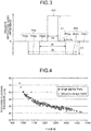
- FIG. 3 is a view illustrating a trench-index refractive index profile in the radial direction from the central axes of the cores.
- a profile P21 illustrates the refractive index profile of the cores 11a or the cores 11b
- a profile P22 illustrates the refractive index profile of the cladding portion 12.
- the cladding portion 12 includes three regions having profiles P22a, P22b, P22c.
- the profile P22a is a refractive index profile of an adjacent region surrounding the outer peripheries of the cores 11a or the cores 11b, and the adjacent region is made of pure silica glass.
- the profile P22b is a refractive index profile of a trench layer surrounding the outer periphery of the adjacent region.
- the trench layer is a region with which dopant for decreasing the refractive index, such as fluorine (F).
- the profile P22c is a refractive index profile of a reference refractive index region surrounding the outer periphery of the trench region.
- the reference refractive index region is made of pure silica glass.
- the core diameter of the cores 11a or the cores 11b is 2a, and the relative refractive-index difference of the cores 11a or the cores 11b to the adjacent region is ⁇ 1.
- the relative refractive-index difference of the adjacent region to the reference refractive index region is ⁇ 2 and is 0% in the present embodiment.
- the relative refractive-index difference of the trench layer to the reference refractive index region is ⁇ 3.
- the outside diameter of the adjacent region in other words, the inside diameter of the trench layer is 2b, and the outside diameter of the trench layer is 2c.
- W type is to be included in a trench-index type.
- the outside diameter (cladding diameter) of the cladding portion 12 in the multi-core fiber 10 is preferably 125 ⁇ m. If the outside diameter thereof is 125 ⁇ m, the multi-core fiber 10 is versatile, and a complication can be prevented, such as a need to prepare a new connecting tool for connection to other optical elements, for example, another multi-core fiber 10 and an optical part.
- the cladding thicknesses refer to respective thicknesses of the cladding portion 12 surrounding the cores 11a, 11b. Because the cores 11a, 11b are eccentric to the center of the cladding portion 12, the cladding thickness varies with their directions. For this reason, as indicated by a distance t in FIG. 1 , the shortest distance from the outer peripheral surface of the cores 11b to the outer peripheral surface of the cladding portion 12 is to be the minimum cladding thickness. Likewise, the minimum cladding thickness is also specified for the cores 11a.
- the minimum cladding thicknesses affect the cut-off wavelength in the cores. For this reason, in a single-core fiber in which a core is arranged at the center of a cladding portion, computer simulations of the cut-off wavelength ⁇ cc and the minimum cladding thickness (required cladding thickness) necessary to achieve the cut-off wavelength were performed in a case in which the core diameter 2a was changed in various ways relative to a refractive index profile (step-index type and trench-index type) conforming to G.652 standard or G.657A standard.
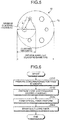
- FIG. 4 is a view illustrating the relation between ⁇ cc and the required cladding thickness. It was found that, in both step-index type and trench-index type, as ⁇ cc increases, the required cladding thickness decreases. Additionally, as is evident from FIG. 4 , the required cladding thickness of the multi-core fiber 10 is preferably equal to or greater than 30 ⁇ m.
- the cladding thickness of the multi-core fiber 10 is preferably equal to or less than 50 ⁇ m, so that the cladding thickness is preferably in the range from 30 ⁇ m to 50 ⁇ m.
- FIG. 5 is a view illustrating the outside diameter (cladding diameter) of the multi-core fiber 10, the cladding thickness, the minimum cladding thickness, and the distance (pitch) d between cores that are closest to each other.
- the cladding diameter can be 125 ⁇ m while crosstalk of light between the cores closest to each other is kept equal to or less than -30 dB per a length of 100 m.
- the minimum cladding thickness is to be 30 ⁇ m
- the cladding diameter can be 125 ⁇ m while the crosstalk is kept equal to or less than -30 dB per a length of 100 m. Consequently, the distance d is preferably in the range from 12.5 ⁇ m to 32.5 ⁇ m.
- Table 3 illustrates profile parameters and propagation refractive indexes conforming to G.652 standard or G.657A standard.
- the propagation refractive indexes are obtained by computer simulations using the profile parameters.
- b and c which are the parameters for the trench-index type, are expressed as b/a and b/c that have been normalized by a.
- Table 4 illustrates optical propagation characteristics obtained by computer simulations using the parameters shown in Table 3, as well as G.652A standard and G.657A2 standard. Note that ( ⁇ 50 ⁇ m) in the cladding thickness indicates a preferred range of cladding thickness so that the cladding diameter can be 125 ⁇ m. As shown in Table 4, the step-index type obtained the propagation characteristics conforming to G.652A standard and a cladding thickness of 40 ⁇ m. Also, the trench-index type obtained the propagation characteristics conforming to G.657A2 standard and a cladding thickness of 39 ⁇ m.
- Table 5 illustrates profile parameters and propagation refractive indexes conforming to G.654 standard.
- Table 6 illustrates optical propagation characteristics obtained by computer simulations using the parameters shown in Table 5, as well as G.654A/C, G.654B, and G.654D standards.
- the step-index type obtained the propagation characteristics conforming to G.654B standard and a cladding thickness of 37 ⁇ m.
- the trench-index type obtained the propagation characteristics conforming to G.654A/C and G.654B standards and a cladding thickness of 33 ⁇ m.
- the multi-core fiber 10 can therefore be implemented by applying any one of the refractive index profiles in Table 3 to the cores 11a and applying any one of the refractive index profiles in Table 5 to the cores 11b.
- a difference in propagation refractive index between the cores 11a, 11b of the multi-core fiber 10 thus implemented is 0.00048 in a case in which both are of step-index type, and is 0.00056 in a case in which both are of trench-index type.
- the values are sufficiently large as heterogeneous cores.
- ⁇ 1 has the same value, which is 0.37% in both tables, and 2a has values different from each other, which are 9.0 ⁇ m and 10.5 ⁇ m in Table 3 and Table 5, respectively.
- ⁇ 1, ⁇ 3, b/a, and c/a all have the same values, which are 0.36%, -0.60%, 3, and 4, respectively, in both tables, and 2a has values different from each other, which are 8.0 ⁇ m and 9.5 ⁇ m in Table 3 and Table 5, respectively.
- the profile parameters conforming to G.654 standard and the profile parameters conforming to G.652 standard or G.657A standard can be achieved by making the profile parameters equal to each other except for the core diameters. Consequently, when the multi-core fiber 10 is manufactured, a core preform for fabricating the cores conforming to one of the standards can first be prepared, and, by stretching this core preform, for example, the core diameter can be changed to prepare a core preform for manufacturing the cores conforming to the other standard, thereby improving manufacturability. The details thereof will be described later.
- Step S101 Three core preforms for a first standard are prepared at Step S101.
- the core preforms are used to fabricate cores that have the propagation characteristics conforming to G.654 standard, and includes a core and a cladding portion.
- the core preforms are used to fabricate cores that have the propagation characteristics conforming to G.652 standard or G.657A standard, and includes a core and a cladding portion.
- the core preforms for the first and the second standards can be fabricated by combining the publicly known vapor axial deposition (VAD) and outside vapor deposition (OVD) methods.
- an optical fiber preform is fabricated by using the three core preforms for the first standard and the three core preforms for the second standard at Step S103.
- the optical fiber preform can be fabricated by using the publicly known stack and draw or drilling method.
- the multi-core fiber 10 is fabricated by drawing the optical fiber preform at Step S104. In this manner, the multi-core fiber 10 can be manufactured.
- the profile parameters conforming to G.654 standard and the profile parameters conforming to G.652 standard or G.657A standard can be achieved by making the profile parameters equal to each other except for the core diameters.
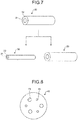
- a preparation process of core preforms at Steps S101, S102 mentioned above can be performed as an example illustrated in FIG. 7 .
- core preforms for the first standard six core preforms 20 for the first standard are first fabricated that includes a core 21 and a cladding portion 22. Subsequently, while three core preforms 20 for the first standard are left untouched, the other three core preforms 20 for the first standard are heated and stretched by using flames or an electric furnace, core preforms 30 for the second standard are fabricated that includes a core 31 and a cladding portion 32.
- the core preforms 20 for the first standard when the core preforms 20 for the first standard are heated and stretched, the core diameter thereof alone can be changed while the values of ⁇ 1, ⁇ 3, b/a, and c/a are kept, so that the core preforms 30 for the second standard can be fabricated by heating and stretching the core preforms 20 for the first standard.
- core preforms conforming to standards different from each other are not manufactured separately, but a part of the manufacturing process can be standardized, thereby improving manufacturability.
- first holes 41 and three second holes 42 are first drilled in a cylindrical glass rod 40 made of pure silica glass, in parallel with the central axis thereof.
- the first holes 41 each have such an inside diameter as to accommodate the outside diameter of the core preforms 20 for the first standard.
- the second holes 42 each have such an inside diameter as to accommodate the outside diameter of the core preforms 30 for the second standard, and have an inside diameter smaller than that of the first holes 41.
- the first holes 41 and the second holes 42 are arrayed in a regular hexagonal shape so as to be the array of the cores 11a, 11b of the multi-core fiber 10.
- the core preforms 20 for the first standard and the core preforms 30 for the second standard are respectively inserted into the first holes 41 and the second holes 42 of the glass rod 40.
- the glass rod 40, and the core preforms 20 for the first standard and the core preforms 30 for the second standard are then heated to be integral with each other, so that an optical fiber preform is fabricated.
- Optical fiber preforms thus fabricated are drawn, whereby the multi-core fiber 10 can be manufactured.
- Integrating the glass rod 40, the core preforms 20 for the first standard, and the core preforms 30 for the second standard by heating is not necessarily performed in the fabricating process of an optical fiber preform, and may be performed by heating for drawing in a fabricating process of a multi-core fiber.
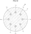
- FIG. 10 is a schematic cross-sectional diagram perpendicular to the longitudinal direction of a multi-core fiber according to a second embodiment.
- a multi-core fiber 10A includes, as a plurality of, specifically, eight cores, four cores 11a and four cores 11b.
- the multi-core fiber 10A also includes the cladding portion 12 formed around the outer peripheries of the cores 11a, 11b.
- the cores 11a, 11a and the cladding portion 12 are the same as the corresponding components in the multi-core fiber 10, and description is thus omitted of the constituent materials, the refractive index profiles, and the standards to which the propagation characteristics conform.
- the cores 11a, 11b are arrayed alternately in an annular shape.
- the cores 11a, 11b can be said to be arrayed in a regular octagonal shape.
- cores closest to a core 11a are the cores 11b
- cores closest to a core 11b are the cores 11a.
- cores that are closest to each other conform to standards different from each other, so that the multi-core fiber 10A is versatile as with the multi-core fiber 10, the pitch can be decreased, and the space density can be increased.
- FIG. 11 is a schematic cross-sectional diagram perpendicular to the longitudinal direction of a multi-core fiber according to a third embodiment.
- a multi-core fiber 10B includes, as a plurality of, specifically, nine cores, five cores 11a and four cores 11b.
- the state of the multi-core fiber 10B also includes the cladding portion 12 formed around the outer peripheries of the cores 11a, 11b.
- the cores 11a, 11b and the cladding portion 12 are the same as the corresponding components in the multi-core fiber 10, and description is thus omitted of the constituent materials, the refractive index profiles, and the standards to which the propagation characteristics conform.
- the cores 11a, 11b are arrayed alternately in a tetragonal lattice shape.
- cores closest to a core 11a are the cores 11b
- cores closest to a core 11b are the cores 11a.
- cores that are closest to each other conform to standards different from each other, so that the multi-core fiber 10B is versatile as with the multi-core fiber 10, the pitch can be decreased, and the space density can be increased.
- the array of the cores in the multi-core fibers according to the present invention is not limited to the triangular lattice shape, the annular shape, and the tetragonal lattice shape mentioned above as long as the array is such that cores that are closest to each other conform to standards different from each other, and the cores may be arrayed in various ways.
- FIG. 12 is a schematic configuration diagram of an optical transmission system according to a fourth embodiment.
- This optical transmission system 100 includes an optical transmission device 110, an optical reception device 120, and the multi-core fiber 10 according to the first embodiment.
- the optical transmission device 110 includes six optical transmitters having a light source, such as a semiconductor laser, and an optical input unit.
- the optical transmitters each output a signal light beam that has a wavelength included in a wavelength band in use and that has been modulated by a modulating signal.
- the wavelength band in use is a wavelength band to be used for optical fiber communications, and is not particularly limited.
- the optical input unit is configured by including publicly known fan-in, and inputs, to the cores 11a, 11b of the multi-core fiber 10, the six signal light beams that have been output from the optical transmitters. In this manner, the cores 11a, 11b propagate the six signal light beams.
- the optical reception device 120 includes six optical receivers having a photoreceptor, such as a photodiode, and an optical output unit.
- the optical output unit is configured by including publicly known fan-out, and extracts and outputs the six signal light beams that have been transmitted by the cores 11a, 11b.
- the optical receivers receive the respective signal light beams that have been output, and demodulate the modulating signals included in the signal light beams.
- This optical transmission system 100 can have the versatility of use and the effect of increasing the space density because the optical transmission system 100 uses the multi-core fiber 10 according to the first embodiment as an optical transmission fiber.
- the optical transmission system 100 can be used to practice various optical transmission methods.
- the optical transmission system 100 can be used to make coarse wavelength division multiplexing (CWDM) optical transmission and dense WDM (DWDM) optical transmission simultaneously.
- CWDM optical transmission refers to optical transmission that uses CWDM signals obtained by wavelength multiplexing a plurality of signal light beams having a wavelength of equal to or greater than 1260 nm.
- the CWDM signal light beams are obtained by arraying signal light beams at intervals of 20 nm in a wavelength band from 1271 nm to 1611 nm, for example.
- the DWDM optical transmission refers to optical transmission that uses DWDM signals obtained by wavelength multiplexing a plurality of signal light beams having a wavelength of equal to or greater than 1530 nm.
- the DWDM signal light beams are obtained by arraying signal light beams at intervals of 100 GHz, 200 GHz or the like in a wavelength band from approximately 1530 nm to approximately 1624 nm, for example.
- the optical transmission device 110 inputs the CWDM signal light beams to the cores 11a of the multi-core fiber 10.
- the optical transmission device 110 also inputs the DWDM signal light beams to the cores 11b.
- the CWDM signal light beams can be propagated in a single mode
- the DWDM signal light beams can be propagated in a single mode.
- a core 11a and a core 11b that are closest to each other have wavelength bands of WDM signals to be transmitted different from each other, which can prevent interference between the WDM signals.
- FIG. 13 is a schematic configuration diagram of an optical transmission system according to a fifth embodiment.
- This optical transmission system 200 includes an optical transmission and reception device 210, an optical transmission and reception device 220, and the multi-core fiber 10 according to the first embodiment.
- the optical transmission and reception devices 210, 220 are configured so as to be able to achieve bidirectional transmission.
- the optical transmission and reception devices 210, 220 each include six optical transmitters, six optical receivers, and an optical input and output unit.
- the optical transmitters each output a signal light beam that has a wavelength included in a wavelength band in use and that has been modulated by a modulating signal.
- the wavelength band in use is a wavelength band to be used for optical fiber communications, and is not particularly limited.
- the optical input and output unit includes publicly known fan-in and an optical multiplexer/demultiplexer. This fan-in functions as fan-out as well.
- the optical input and output unit inputs, to the cores 11a, 11b of the multi-core fiber 10, the six signal light beams that have been output from the optical transmitters. In this manner, the cores 11a, 11b propagate the six signal light beams. Meanwhile, in each of the optical transmission and reception devices 210, 220, the optical input and output unit extracts and outputs the six signal light beams that have been transmitted from the other optical transmission and reception device via the cores 11a, 11b.
- the optical receivers receive the respective signal light beams that have been output, and demodulate the modulating signals included in the signal light beams.
- This optical transmission system 200 can achieve bidirectional transmission, and can also have the versatility of use and the effect of increasing the space density because the optical transmission system 100 uses the multi-core fiber 10 according to the first embodiment as an optical transmission fiber. Additionally, interference of signal light beams in bidirectional transmission can be prevented by varying directions of optical transmission between a core 11a and a core 11b that are closest to each other.
- all of the cores 11a, 11b of the multi-core fiber 10 are used to make optical transmission, but at least one of the cores 11a, 11b may be used to make optical transmission.
- a publicly known marker may be provided to the multi-core fibers according to the embodiments mentioned above.
- a marker can be implemented by providing, in the cladding portion, for example, a region having a refractive index different from that of the cladding portion.
- the embodiments mentioned above do not limit the present invention.
- the present invention also includes any invention that is constituted by combining the components described above, as appropriate.
- a person skilled in the art can easily derive further effects and modifications. Therefore, a wider range of aspects of the present invention is not limited by the embodiments mentioned above, and various changes can be made.
- multi-core fibers and a method of manufacturing the same, and an optical transmission system and an optical transmission method according to the present invention are useful for a multi-core fiber that uses a plurality of heterogeneous cores.
Landscapes
- Engineering & Computer Science (AREA)
- Physics & Mathematics (AREA)
- Chemical & Material Sciences (AREA)
- Computer Networks & Wireless Communication (AREA)
- Signal Processing (AREA)
- Materials Engineering (AREA)
- Manufacturing & Machinery (AREA)
- Geochemistry & Mineralogy (AREA)
- General Life Sciences & Earth Sciences (AREA)
- Organic Chemistry (AREA)
- Life Sciences & Earth Sciences (AREA)
- Electromagnetism (AREA)
- General Physics & Mathematics (AREA)
- Optics & Photonics (AREA)
- Optical Communication System (AREA)
- Optical Fibers, Optical Fiber Cores, And Optical Fiber Bundles (AREA)
- Manufacture, Treatment Of Glass Fibers (AREA)
- Optical Couplings Of Light Guides (AREA)
Abstract
Description
- The present invention relates to multi-core fibers and a method of manufacturing the same, and an optical transmission system and an optical transmission method.
- Conventionally, studies have been conducted actively in order to increase the number of space division multiplexing and the space density by using heterogeneous cores having propagation refractive indexes different from each other in a multi-core fiber (Patent Literature 1 and Non Patent Literature 1). For example, Non Patent Literature 1 has reported the result of arranging 30 cores in a cladding portion having an outside diameter of 228 µm at a high density.
- Patent Literature 1: International publication No.
WO 2013/027776 - Non Patent Literature 1: Y. Amma et al., "High-density Multi-core Fiber with Heterogeneous Core Arrangement" OFC 2015, paper Th4C.4, (2015)
- For optical fibers, standards are defined on optical propagation characteristics and other characteristics. For example, ITU-T (the International Telecommunication Union's Telecommunication Standardization Sector) Recommendations are standards that are widely accepted in the world.
- Bringing the multi-core fiber that uses heterogeneous cores (hereinafter referred to as a heterogeneous multi-core fiber, as appropriate) into conformity with the standards increases the versatility of use thereof, which is preferable in actual use. However, conformity of the heterogeneous multi-core fiber to the standards has not necessarily been considered sufficiently thus far.
- The present invention is made in view of the foregoing, and it is an object of the present invention to provide multi-core fibers that are versatile and the space density of which can be increased, and a method of manufacturing the same, as well as an optical transmission system and an optical transmission method.
- To resolve the above problem and attain the object, a multi-core fiber according to an embodiment of the present invention includes: a plurality of cores; and a cladding portion formed around outer peripheries of the cores. Further, the cores each have a propagation characteristic conforming to any one of a plurality of standards for optical propagation characteristics, and of the cores, cores that are closest to each other conform to standards different from each other.
- In the multi-core fiber according to an embodiment of the present invention, the standards include ITU-T G.652 standard, G.657A standard, and G.654 standard.
- In the multi-core fiber according to an embodiment of the present invention, of the cores that are closest to each other, a first core has a propagation characteristic conforming to G.652 standard or G.657A standard, and a second core has a propagation characteristic conforming to G.654 standard.
- In the multi-core fiber according to an embodiment of the present invention, the propagation characteristic is at least one of a cut-off wavelength, a mode field diameter, a macrobending loss, and a chromatic dispersion characteristic.
- In the multi-core fiber according to an embodiment of the present invention, the first core and the cladding portion, and the second core and the cladding portion have parameters for specifying a refractive index profile equal to each other except for a core diameter.
- In the multi-core fiber according to an embodiment of the present invention, the refractive index profile s step-index type or trench-index type.
- In the multi-core fiber according to an embodiment of the present invention, a cladding thickness is in a range from 30 µm to 50 µm.
- In the multi-core fiber according to an embodiment of the present invention, a distance between the cores that are closest to each other is in a range from 12.5 µm to 32.5 µm.
- A method of manufacturing a multi-core fiber according to an embodiment of the present invention, includes: preparing a plurality of core preforms for fabricating a core that has a propagation characteristic conforming to any one of a plurality of standards for optical propagation characteristics, the core preforms conforming to standards different from each other; fabricating an optical fiber preform by using the core preforms; and fabricating a multi-core fiber by drawing the optical fiber preform.
- In the method of manufacturing a multi-core fiber according to an embodiment of the present invention, in preparing the core preforms, preparing a core preform for a first standard for fabricating a core that has a propagation characteristic conforming to ITU-T G.654 standard, and preparing a core preform for a second standard for fabricating a core that has a propagation characteristic conforming to ITU-T G.652 standard or G.657A standard by stretching the core preform for a first standard.
- In the method of manufacturing a multi-core fiber according to an embodiment of the present invention, in fabricating the optical fiber preform, drilling, in a glass rod, a first hole that has such an inside diameter as to accommodate an outside diameter of the core preform for a first standard and a second hole that has such an inside diameter as to accommodate an outside diameter of the core preform for a second standard, inserting the core preform for a first standard into the first hole, and inserting the core preform for a second standard into the second hole.
- In the method of manufacturing a multi-core fiber according to an embodiment of the present invention, in fabricating the optical fiber preform or in fabricating the multi-core fiber, integrating the glass rod, the core preform for a first standard, and the core preform for a second standard by heating.
- An optical transmission system according to an embodiment of the present invention includes: the multi-core fiber; an optical transmission device inputting a signal light beam into at least one of the cores of the multi-core fiber; and an optical reception device receiving the signal light beam propagated through the multi-core fiber.
- In the optical transmission system according to an embodiment of the present invention, the optical transmission device inputs, to a core that has a propagation characteristic conforming to G.652 standard or G.657A standard, a CWDM signal obtained by wavelength multiplexing a plurality of signal light beams having a wavelength of equal to or greater than 1260 nm, and inputs, to a core that has a propagation characteristic conforming to G.654 standard, a DWDM signal obtained by wavelength multiplexing a plurality of signal light beams having a wavelength of equal to or greater than 1530 nm.
- In the optical transmission system according to an embodiment of the present invention, the optical transmission device and the optical reception device are configured to be capable of making bidirectional transmission.
- In an optical transmission method according to an embodiment of the present invention using the optical transmission system, by using a core that has a propagation characteristic conforming to G.652 standard or G.657A standard, CWDM optical transmission is made that uses a CWDM signal light beam obtained by wavelength multiplexing a plurality of signal light beams having a wavelength of equal to or greater than 1260 nm, and, by using a core that has a propagation characteristic conforming to G.654 standard, DWDM optical transmission is made that uses a DWDM signal light beam obtained by wavelength multiplexing a plurality of signal light beams having a wavelength of equal to or greater than 1530 nm.
- In the optical transmission method according to an embodiment of the present invention using the optical transmission system, bidirectional transmission is made. Advantageous Effects of Invention
- According to the present invention, the effect is exerted of being able to implement multi-core fibers that are versatile and in which the space density can be increased.
-
-
FIG. 1 is a schematic cross-sectional diagram of a multi-core fiber according to a first embodiment. -
FIG. 2 is a view illustrating a step-index profile that is an example of a refractive index profile. -
FIG. 3 is a view illustrating a trench-index profile that is an example of a refractive index profile. -
FIG. 4 is a view illustrating the relation between λcc and the required cladding thickness. -
FIG. 5 is a view illustrating the outside diameter (cladding diameter) of the multi-core fiber, the cladding thickness, the minimum cladding thickness, and the distance between cores that are closest to each other. -
FIG. 6 is a diagram illustrating an example of a flow of manufacturing the multi-core fiber. -
FIG. 7 is a diagram illustrating an example of a preparation process of core preforms. -
FIG. 8 is a diagram illustrating an example of a fabricating process of an optical fiber preform. -
FIG. 9 is a diagram illustrating an example of a fabricating process of an optical fiber preform. -
FIG. 10 is a schematic cross-sectional diagram of a multi-core fiber according to a second embodiment. -
FIG. 11 is a schematic cross-sectional diagram of a multi-core fiber according to a third embodiment. -
FIG. 12 is a schematic configuration diagram of an optical transmission system according to a fourth embodiment. -
FIG. 13 is a schematic configuration diagram of an optical transmission system according to a fifth embodiment. - Embodiments of the present invention will be described in detail below with reference to the drawings. The embodiments to be described below do not limit the present invention. In the drawings, the same reference sign is given to the same or corresponding components, as appropriate. In the present specification, cut-off wavelength refers to cable cut-off wavelength defined in ITU-T G.650.1. Note that Other terms that are not defined in particular in the present specification are to be pursuant to the definitions and measurement methods in ITU-T G.650.1.
- The inventor has earnestly considered an increase in space density of a heterogeneous multi-core fiber and conformity to standards. As a result, the following has been found: if all heterogeneous cores are designed under the condition of being in conformity with a standard, a sufficient difference in propagation refractive index cannot be set between the heterogeneous cores, and trying to keep crosstalk of light within tolerance adds constraints to the increase in space density.
- Consequently, the inventor has conceived of a plurality of cores being such that each have propagation characteristics conforming to any one of a plurality of standards for optical propagation characteristics, and also, cores that are closest to each other conforming to standards different from each other, as a result of earnest consideration. In this manner, heterogeneous cores can be made to adjoin each other that have a sufficient difference in propagation refractive index therebetween, and that, at the same time, all conform to standards, so that a multi-core fiber can be implemented that is versatile and the space density of which can be increased.
-
FIG. 1 is a schematic cross-sectional diagram perpendicular to the longitudinal direction of a multi-core fiber according to a first embodiment. Amulti-core fiber 10 includes, as a plurality of, specifically, six cores, threecores 11a and threecores 11b. Themulti-core fiber 10 also includes acladding portion 12 formed around the outer peripheries of thecores - The
cores cladding portion 12 are both made of silica glass. Thecladding portion 12 has a refractive index lower than the maximum refractive index of thecores cores cladding portion 12 is made of pure silica glass that includes no dopant for adjusting the refractive index, for example. - The
cores cladding portion 12, and are regular hexagonal in form. This arrangement can be said to be such that cores are arranged at lattice points except for the center in a hexagonal closest packing lattice. If thecores - In this arrangement, cores closest to a
core 11a are the adjacent twocores 11b, and cores closest to a core 11b are the adjacent twocores 11a. The distances (pitches) between these closest cores are all d. The pitch betweencores 11a and the pitch betweencores 11b are both √3×d. - The
cores cores 11a have propagation characteristics conforming to G.652 standard or G.657A standard. Thecores 11b have propagation characteristics conforming to G.654 standard. - As shown in Table 1, G.652 standard includes G.652A standard and G.652B standard, and G.657A standard includes G.657A1 standard and G.6527A2 standard. As shown in Table 2, G.654 standard includes G.654A standard, G.654B standard, G.654C standard, and G.654D standard. Each standard defines optical propagation characteristics. Herein, optical propagation characteristics refer to the mode field diameter (MFD) at a specific wavelength (1310 nm or 1550 nm), the cable cut-off wavelength (λcc), the macrobending loss, chromatic dispersion characteristics (the chromatic dispersion at a specific wavelength (1550 nm), the zero-dispersion wavelength, or the dispersion slope at the zero-dispersion wavelength). The macrobending loss is specified by an increment in transmission loss for the specific number of turns or an increment in transmission loss per unit length at a specific wavelength (1550 nm or 1625 nm) and at a specific bend radius (30 mm or 10 mm). In Table 2, "A/C" indicates G.654A standard and G.654C standard. In other words, G.654A standard and G.654C standard define common standards for the propagation characteristics shown in Table 2.
Table 1 Item Unit G.652 standard G.657 standard A B A1 A2 MFD@1 310 nm µm 8.6-9.5 8.6-9.5 8.6-9.2 8.6-9.2 λcc nm ≤1260 ≤1260 ≤1260 ≤1260 Macro bendi ng loss dB (dB/m) ≤0.1/100 turns (≤0.0053) @30 mm @1550 nm ≤0.1/100 turns (≤0.0053) @30 mm @1625 nm ≤0.75/1 turns (≤11.94) @10 mm @1550 nm ≤0.1/10 turns (≤1.59) @10 mm @1550 nm Zero-dispe rsion wavel ength nm 1300-1324 1300-1324 1300-1324 1300-1324 Dispe rsion slope ps/nm2 /km ≤0.092 ≤0.092 ≤0.092 ≤0.092 Table 2 Item Unit G.654 standard A/C B D MFD@1550 nm µm 9.5-10.5 9.5-13.0 11.5-15.0 λcc nm ≤1530 ≤1530 ≤1530 Macrobending loss dB/100 turn (dB/m) ≤0.5 (≤0.0265) @30 mm @1625 nm ≤0.5 (≤0.0265) @30 mm @1625 nm ≤2.0 (≤0.106) @30 mm @1625 nm Chromatic dispersion@1550 nm ps/nm/km ≤20 ≤22 ≤23 Dispersion slope ps/nm2/km ≤0.070 ≤0.070 ≤0.070 - In the first embodiment, all the
cores 11a conform to the propagation characteristics of G.652A standard shown in Table 1, and all thecores 11b conform to the propagation characteristics of G.654A standard shown in Table 1. This enables each of thecores cores cores cores - For the
cores cladding portion 12, refractive index profiles are set so as to achieve conformity to these standards. The refractive index profiles to be set are not particularly limited. However, step-index type and trench-index type, for example, have commonly been used and are preferable in terms of manufacturability and design. -
FIG. 2 is a view illustrating a step-index refractive index profile in the radial direction from the central axes of the cores. InFIG. 2 , a profile P11 illustrates the refractive index profile of thecores 11a or thecores 11b, and a profile P12 illustrates the refractive index profile of thecladding portion 12. The refractive index profiles are indicated by relative refractive-index differences with respect to thecladding portion 12. The diameter (core diameter) of thecores 11a or thecores 11b is 2a, and the relative refractive-index difference of thecores 11a or thecores 11b with respect to thecladding portion 12 is Δ1. Parameters for specifying the step-index refractive index profile (hereinafter referred to as profile parameters, as appropriate) are a and Δ1. - While the refractive index profile of the
cores 11a or thecores 11b is sometimes of step-index type having a shape that is geometrically ideal, the refractive index profile thereof has a top shape that is not flat but uneven due to a manufacturing characteristic or having a shape trailing from the top to the bottom at other times. In this case, at least a part of values (such as the mean value, the maximum value, and the minimum value in the top region that determine Δ1) of the top of the refractive index profile within a range of acore diameter 2a serves as an index for determining Δ1. The same holds true for Δ1 in the case of trench-index type below. -
FIG. 3 is a view illustrating a trench-index refractive index profile in the radial direction from the central axes of the cores. InFIG. 3 , a profile P21 illustrates the refractive index profile of thecores 11a or thecores 11b, and a profile P22 illustrates the refractive index profile of thecladding portion 12. - As the profile P22 illustrates, the
cladding portion 12 includes three regions having profiles P22a, P22b, P22c. The profile P22a is a refractive index profile of an adjacent region surrounding the outer peripheries of thecores 11a or thecores 11b, and the adjacent region is made of pure silica glass. The profile P22b is a refractive index profile of a trench layer surrounding the outer periphery of the adjacent region. The trench layer is a region with which dopant for decreasing the refractive index, such as fluorine (F). The profile P22c is a refractive index profile of a reference refractive index region surrounding the outer periphery of the trench region. The reference refractive index region is made of pure silica glass. - The core diameter of the
cores 11a or thecores 11b is 2a, and the relative refractive-index difference of thecores 11a or thecores 11b to the adjacent region is Δ1. The relative refractive-index difference of the adjacent region to the reference refractive index region is Δ2 and is 0% in the present embodiment. The relative refractive-index difference of the trench layer to the reference refractive index region is Δ3. The outside diameter of the adjacent region, in other words, the inside diameter of the trench layer is 2b, and the outside diameter of the trench layer is 2c. Thus, the profile parameters for the trench-index refractive index profile are a, b, c, Δ1, and Δ3. In the case of a=b, no adjacent region is present, thereby providing what is called a W-shaped refractive index profile. In the present specification, W type is to be included in a trench-index type. - Preferred structural parameters for the
multi-core fiber 10 will be described next. First, the outside diameter (cladding diameter) of thecladding portion 12 in themulti-core fiber 10 is preferably 125 µm. If the outside diameter thereof is 125 µm, themulti-core fiber 10 is versatile, and a complication can be prevented, such as a need to prepare a new connecting tool for connection to other optical elements, for example, anothermulti-core fiber 10 and an optical part. - Subsequently, preferred cladding thicknesses in the
multi-core fiber 10 will be described. The cladding thicknesses refer to respective thicknesses of thecladding portion 12 surrounding thecores cores cladding portion 12, the cladding thickness varies with their directions. For this reason, as indicated by a distance t inFIG. 1 , the shortest distance from the outer peripheral surface of thecores 11b to the outer peripheral surface of thecladding portion 12 is to be the minimum cladding thickness. Likewise, the minimum cladding thickness is also specified for thecores 11a. - The minimum cladding thicknesses affect the cut-off wavelength in the cores. For this reason, in a single-core fiber in which a core is arranged at the center of a cladding portion, computer simulations of the cut-off wavelength λcc and the minimum cladding thickness (required cladding thickness) necessary to achieve the cut-off wavelength were performed in a case in which the
core diameter 2a was changed in various ways relative to a refractive index profile (step-index type and trench-index type) conforming to G.652 standard or G.657A standard. -
FIG. 4 is a view illustrating the relation between λcc and the required cladding thickness. It was found that, in both step-index type and trench-index type, as λcc increases, the required cladding thickness decreases. Additionally, as is evident fromFIG. 4 , the required cladding thickness of themulti-core fiber 10 is preferably equal to or greater than 30 µm. - Meanwhile, considering that the cladding diameter of the
multi-core fiber 10 is to be 125 µm, the cladding thickness is preferably equal to or less than 50 µm, so that the cladding thickness is preferably in the range from 30 µm to 50 µm.FIG. 5 is a view illustrating the outside diameter (cladding diameter) of themulti-core fiber 10, the cladding thickness, the minimum cladding thickness, and the distance (pitch) d between cores that are closest to each other. In themulti-core fiber 10, given that the minimum cladding thickness is to be 50 µm, if the distance d between thecores - Subsequently, a concrete example of a preferred refractive index profile in the
multi-core fiber 10 will be described. Table 3 illustrates profile parameters and propagation refractive indexes conforming to G.652 standard or G.657A standard. The propagation refractive indexes are obtained by computer simulations using the profile parameters. Also, b and c, which are the parameters for the trench-index type, are expressed as b/a and b/c that have been normalized by a. - Table 4 illustrates optical propagation characteristics obtained by computer simulations using the parameters shown in Table 3, as well as G.652A standard and G.657A2 standard. Note that (≤50 µm) in the cladding thickness indicates a preferred range of cladding thickness so that the cladding diameter can be 125 µm. As shown in Table 4, the step-index type obtained the propagation characteristics conforming to G.652A standard and a cladding thickness of 40 µm. Also, the trench-index type obtained the propagation characteristics conforming to G.657A2 standard and a cladding thickness of 39 µm.
Herein, for the cladding thickness, bringing the cores into conformity with G.652 standard or G.657A standard generally constitutes a limiting factor, and, in particular, the cut-off wavelength constitutes a limiting factor. Thus, as in Table 4, setting the cut-off wavelength at a value as close to the upper limit as possible enables the cladding thickness to be small, which is preferable. Note that "E" in the table indicates a power of 10, and that 5.3E-3 means 5.3×10⁻³, for example. The same holds true for the following tables.Table 3 Item Δ1 Δ3 b/a c/a 2a Propagation refractive index Unit [%] [%] [µm] Step-index type 0.37 - - - 9.0 1.44701 Trench-index type 0.36 -0.60 3 4 8.0 1.44654 Table 4 Item Zero-dispersion wavelength Dispersion slope MFD λcc Macrobending loss Cladding thickness Unit [nm] [ps/nm2/km] [µm] @1310 nm [nm] @22 m [dB/m] @1550 nm [µm] G.652 A standard 1300-1324 ≤0.092 8.6-9.5 ≤126 0 ≤5.3E-3@30 nm (≤50) G.657 A2 standard 1300-1324 ≤0.092 8.6-9.2 ≤126 0 ≤1.59@10 nm (≤50) Step-index type 1304 0.090 9.1 1254 0.3E-7@30 nm 40 Trench-index type 1317 0.088 8.8 1252 0.26@10 nm 39 - Table 5 illustrates profile parameters and propagation refractive indexes conforming to G.654 standard. Table 6 illustrates optical propagation characteristics obtained by computer simulations using the parameters shown in Table 5, as well as G.654A/C, G.654B, and G.654D standards. As shown in Table 6, the step-index type obtained the propagation characteristics conforming to G.654B standard and a cladding thickness of 37 µm. Also, the trench-index type obtained the propagation characteristics conforming to G.654A/C and G.654B standards and a cladding thickness of 33 µm.
Table 5 Item Δ1 Δ3 b/a c/a 2a Propagation refractive index Unit [%] [%] [µm] Step-index type 0.37 - - - 10.5 1.44749 Trench-index type 0.36 -0.60 3 4 9.5 1.44710 Table 6 Item Chrom atic dispe rsion Dispers ion slope MFD λcc Macrobe nding loss Claddi ng thickn ess Unit [ps/n m/km] @1550 nm [ps/nm2 /km] [µm] @1550 nm [nm] @22 m [dB/m] @30 nm @1625 nm [µm] G.654 A/C standard ≤20 ≤0.070 9.5-10.5 ≤1530 ≤0.0265 (≤50) G.654 B standard ≤22 ≤0.070 9.5-13.0 ≤1530 ≤0.0265 (≤50) G.654 D standard ≤23 ≤0.070 11.5-15.0 ≤1530 ≤0.106 (≤50) Step-index type 19.4 0.062 10.70 1472 1.1E-8 37 Trench-index type 18.7 0.061 10.43 1495 5.5E-8 33 - The
multi-core fiber 10 can therefore be implemented by applying any one of the refractive index profiles in Table 3 to thecores 11a and applying any one of the refractive index profiles in Table 5 to thecores 11b. A difference in propagation refractive index between thecores multi-core fiber 10 thus implemented is 0.00048 in a case in which both are of step-index type, and is 0.00056 in a case in which both are of trench-index type. The values are sufficiently large as heterogeneous cores. - Incidentally, the profile parameters shown in Table 3 and Table 5 are compared. For the step-index type, Δ1 has the same value, which is 0.37% in both tables, and 2a has values different from each other, which are 9.0 µm and 10.5 µm in Table 3 and Table 5, respectively.
Likewise, For the trench-index type, Δ1, Δ3, b/a, and c/a all have the same values, which are 0.36%, -0.60%, 3, and 4, respectively, in both tables, and 2a has values different from each other, which are 8.0 µm and 9.5 µm in Table 3 and Table 5, respectively. - This means that, in a case in which the types of refractive index profile are the same, the profile parameters conforming to G.654 standard and the profile parameters conforming to G.652 standard or G.657A standard can be achieved by making the profile parameters equal to each other except for the core diameters. Consequently, when the
multi-core fiber 10 is manufactured, a core preform for fabricating the cores conforming to one of the standards can first be prepared, and, by stretching this core preform, for example, the core diameter can be changed to prepare a core preform for manufacturing the cores conforming to the other standard, thereby improving manufacturability. The details thereof will be described later. - An example of a method of manufacturing the
multi-core fiber 10 will be described next with reference to a manufacturing flow inFIG. 6 . First, three core preforms for a first standard are prepared at Step S101. The core preforms are used to fabricate cores that have the propagation characteristics conforming to G.654 standard, and includes a core and a cladding portion. - Subsequently, three core preforms for a second standard are prepared at Step S102. The core preforms are used to fabricate cores that have the propagation characteristics conforming to G.652 standard or G.657A standard, and includes a core and a cladding portion. The core preforms for the first and the second standards can be fabricated by combining the publicly known vapor axial deposition (VAD) and outside vapor deposition (OVD) methods.
- Subsequently, an optical fiber preform is fabricated by using the three core preforms for the first standard and the three core preforms for the second standard at Step S103. The optical fiber preform can be fabricated by using the publicly known stack and draw or drilling method.
- Subsequently, the
multi-core fiber 10 is fabricated by drawing the optical fiber preform at Step S104. In this manner, themulti-core fiber 10 can be manufactured. - Incidentally, as described above, in a case in which the types of refractive index profile are the same, the profile parameters conforming to G.654 standard and the profile parameters conforming to G.652 standard or G.657A standard can be achieved by making the profile parameters equal to each other except for the core diameters. Thus, a preparation process of core preforms at Steps S101, S102 mentioned above can be performed as an example illustrated in
FIG. 7 . - That is, as core preforms for the first standard, six core preforms 20 for the first standard are first fabricated that includes a
core 21 and acladding portion 22. Subsequently, while threecore preforms 20 for the first standard are left untouched, the other threecore preforms 20 for the first standard are heated and stretched by using flames or an electric furnace, core preforms 30 for the second standard are fabricated that includes acore 31 and acladding portion 32. At this time, in the case of trench-index type, for example, when the core preforms 20 for the first standard are heated and stretched, the core diameter thereof alone can be changed while the values of Δ1, Δ3, b/a, and c/a are kept, so that the core preforms 30 for the second standard can be fabricated by heating and stretching the core preforms 20 for the first standard. In this manner, core preforms conforming to standards different from each other are not manufactured separately, but a part of the manufacturing process can be standardized, thereby improving manufacturability. - Subsequently, an example of a fabricating process of an optical fiber preform using the core preforms 20 for the first standard and the core preforms 30 for the second standard that have been prepared as in
FIG. 7 . - As illustrated in
FIG. 8 , threefirst holes 41 and threesecond holes 42 are first drilled in acylindrical glass rod 40 made of pure silica glass, in parallel with the central axis thereof. Thefirst holes 41 each have such an inside diameter as to accommodate the outside diameter of the core preforms 20 for the first standard. Thesecond holes 42 each have such an inside diameter as to accommodate the outside diameter of the core preforms 30 for the second standard, and have an inside diameter smaller than that of the first holes 41. Thefirst holes 41 and thesecond holes 42 are arrayed in a regular hexagonal shape so as to be the array of thecores multi-core fiber 10. - Subsequently, as illustrated in
FIG. 9 , the core preforms 20 for the first standard and the core preforms 30 for the second standard are respectively inserted into thefirst holes 41 and thesecond holes 42 of theglass rod 40. Theglass rod 40, and the core preforms 20 for the first standard and the core preforms 30 for the second standard are then heated to be integral with each other, so that an optical fiber preform is fabricated. Optical fiber preforms thus fabricated are drawn, whereby themulti-core fiber 10 can be manufactured. - Integrating the
glass rod 40, the core preforms 20 for the first standard, and the core preforms 30 for the second standard by heating is not necessarily performed in the fabricating process of an optical fiber preform, and may be performed by heating for drawing in a fabricating process of a multi-core fiber. -
FIG. 10 is a schematic cross-sectional diagram perpendicular to the longitudinal direction of a multi-core fiber according to a second embodiment. Amulti-core fiber 10A includes, as a plurality of, specifically, eight cores, fourcores 11a and fourcores 11b. Themulti-core fiber 10A also includes thecladding portion 12 formed around the outer peripheries of thecores - The
cores cladding portion 12 are the same as the corresponding components in themulti-core fiber 10, and description is thus omitted of the constituent materials, the refractive index profiles, and the standards to which the propagation characteristics conform. - The
cores cores core 11a are thecores 11b, and cores closest to a core 11b are thecores 11a. In this manner, cores that are closest to each other conform to standards different from each other, so that themulti-core fiber 10A is versatile as with themulti-core fiber 10, the pitch can be decreased, and the space density can be increased. -
FIG. 11 is a schematic cross-sectional diagram perpendicular to the longitudinal direction of a multi-core fiber according to a third embodiment. Amulti-core fiber 10B includes, as a plurality of, specifically, nine cores, fivecores 11a and fourcores 11b. The state of themulti-core fiber 10B also includes thecladding portion 12 formed around the outer peripheries of thecores - The
cores cladding portion 12 are the same as the corresponding components in themulti-core fiber 10, and description is thus omitted of the constituent materials, the refractive index profiles, and the standards to which the propagation characteristics conform. - The
cores core 11a are thecores 11b, and cores closest to a core 11b are thecores 11a. In this manner, cores that are closest to each other conform to standards different from each other, so that themulti-core fiber 10B is versatile as with themulti-core fiber 10, the pitch can be decreased, and the space density can be increased. - Furthermore, the array of the cores in the multi-core fibers according to the present invention is not limited to the triangular lattice shape, the annular shape, and the tetragonal lattice shape mentioned above as long as the array is such that cores that are closest to each other conform to standards different from each other, and the cores may be arrayed in various ways.
-
FIG. 12 is a schematic configuration diagram of an optical transmission system according to a fourth embodiment. Thisoptical transmission system 100 includes anoptical transmission device 110, anoptical reception device 120, and themulti-core fiber 10 according to the first embodiment. - The
optical transmission device 110 includes six optical transmitters having a light source, such as a semiconductor laser, and an optical input unit. The optical transmitters each output a signal light beam that has a wavelength included in a wavelength band in use and that has been modulated by a modulating signal. The wavelength band in use is a wavelength band to be used for optical fiber communications, and is not particularly limited. - The optical input unit is configured by including publicly known fan-in, and inputs, to the
cores multi-core fiber 10, the six signal light beams that have been output from the optical transmitters. In this manner, thecores - The
optical reception device 120 includes six optical receivers having a photoreceptor, such as a photodiode, and an optical output unit. - The optical output unit is configured by including publicly known fan-out, and extracts and outputs the six signal light beams that have been transmitted by the
cores - This
optical transmission system 100 can have the versatility of use and the effect of increasing the space density because theoptical transmission system 100 uses themulti-core fiber 10 according to the first embodiment as an optical transmission fiber. - The
optical transmission system 100 can be used to practice various optical transmission methods. - For example, the
optical transmission system 100 can be used to make coarse wavelength division multiplexing (CWDM) optical transmission and dense WDM (DWDM) optical transmission simultaneously. Herein, the CWDM optical transmission refers to optical transmission that uses CWDM signals obtained by wavelength multiplexing a plurality of signal light beams having a wavelength of equal to or greater than 1260 nm. The CWDM signal light beams are obtained by arraying signal light beams at intervals of 20 nm in a wavelength band from 1271 nm to 1611 nm, for example. The DWDM optical transmission refers to optical transmission that uses DWDM signals obtained by wavelength multiplexing a plurality of signal light beams having a wavelength of equal to or greater than 1530 nm. The DWDM signal light beams are obtained by arraying signal light beams at intervals of 100 GHz, 200 GHz or the like in a wavelength band from approximately 1530 nm to approximately 1624 nm, for example. - In this case, the
optical transmission device 110 inputs the CWDM signal light beams to thecores 11a of themulti-core fiber 10. Theoptical transmission device 110 also inputs the DWDM signal light beams to thecores 11b. For thecores 11a that have the propagation characteristics conforming to G.652 standard or G.657A standard, the CWDM signal light beams can be propagated in a single mode, and for thecores 11b that have the propagation characteristics conforming to G.654 standard, the DWDM signal light beams can be propagated in a single mode. Additionally, acore 11a and a core 11b that are closest to each other have wavelength bands of WDM signals to be transmitted different from each other, which can prevent interference between the WDM signals. -
FIG. 13 is a schematic configuration diagram of an optical transmission system according to a fifth embodiment. Thisoptical transmission system 200 includes an optical transmission andreception device 210, an optical transmission andreception device 220, and themulti-core fiber 10 according to the first embodiment. - The optical transmission and
reception devices reception devices - The optical input and output unit includes publicly known fan-in and an optical multiplexer/demultiplexer. This fan-in functions as fan-out as well.
- In each of the optical transmission and
reception devices cores multi-core fiber 10, the six signal light beams that have been output from the optical transmitters. In this manner, thecores reception devices cores - This
optical transmission system 200 can achieve bidirectional transmission, and can also have the versatility of use and the effect of increasing the space density because theoptical transmission system 100 uses themulti-core fiber 10 according to the first embodiment as an optical transmission fiber. Additionally, interference of signal light beams in bidirectional transmission can be prevented by varying directions of optical transmission between a core 11a and a core 11b that are closest to each other. - In the optical transmission systems according to the embodiments mentioned above, all of the
cores multi-core fiber 10 are used to make optical transmission, but at least one of thecores - In order to identify the cores, a publicly known marker may be provided to the multi-core fibers according to the embodiments mentioned above. Such a marker can be implemented by providing, in the cladding portion, for example, a region having a refractive index different from that of the cladding portion.
- The embodiments mentioned above do not limit the present invention. The present invention also includes any invention that is constituted by combining the components described above, as appropriate. A person skilled in the art can easily derive further effects and modifications. Therefore, a wider range of aspects of the present invention is not limited by the embodiments mentioned above, and various changes can be made.
- As described above, multi-core fibers and a method of manufacturing the same, and an optical transmission system and an optical transmission method according to the present invention are useful for a multi-core fiber that uses a plurality of heterogeneous cores. Reference Signs List
-
- 10, 10A, 10B
- Multi-core fiber
- 11a, 11b
- Core
- 12
- Cladding portion
- 100, 200
- Optical transmission system
- 110
- Optical transmission device
- 120
- Optical reception device
- 210, 220
- Optical transmission and reception devices
Claims (17)
- A multi-core fiber comprising:a plurality of cores; anda cladding portion formed around outer peripheries of the cores, whereinthe cores each have a propagation characteristic conforming to any one of a plurality of standards for optical propagation characteristics, andof the cores, cores that are closest to each other conform to standards different from each other.
- The multi-core fiber according to claim 1, wherein the standards include ITU-T G.652 standard, G.657A standard, and G.654 standard.
- The multi-core fiber according to claim 2, wherein, of the cores that are closest to each other, a first core has a propagation characteristic conforming to G.652 standard or G.657A standard, and a second core has a propagation characteristic conforming to G.654 standard.
- The multi-core fiber according to claim 3, wherein the propagation characteristic is at least one of a cut-off wavelength, a mode field diameter, a macrobending loss, and a chromatic dispersion characteristic.
- The multi-core fiber according to claim 4, wherein the first core and the cladding portion, and the second core and the cladding portion have parameters for specifying a refractive index profile equal to each other except for a core diameter.
- The multi-core fiber according to claim 5, wherein the refractive index profile s step-index type or trench-index type.
- The multi-core fiber according to any one of claims 1 to 6, wherein a cladding thickness is in a range from 30 µm to 50 µm.
- The multi-core fiber according to any one of claims 1 to 7, wherein a distance between the cores that are closest to each other is in a range from 12.5 µm to 32.5 µm.
- A method of manufacturing a multi-core fiber, the method comprising:preparing a plurality of core preforms for fabricating a core that has a propagation characteristic conforming to any one of a plurality of standards for optical propagation characteristics, the core preforms conforming to standards different from each other;fabricating an optical fiber preform by using the core preforms; andfabricating a multi-core fiber by drawing the optical fiber preform.
- The method of manufacturing a multi-core fiber according to claim 9, wherein, in preparing the core preforms, preparing a core preform for a first standard for fabricating a core that has a propagation characteristic conforming to ITU-T G.654 standard, and preparing a core preform for a second standard for fabricating a core that has a propagation characteristic conforming to ITU-T G.652 standard or G.657A standard by stretching the core preform for a first standard.
- The method of manufacturing a multi-core fiber according to claim 10, wherein, in fabricating the optical fiber preform, drilling, in a glass rod, a first hole that has such an inside diameter as to accommodate an outside diameter of the core preform for a first standard and a second hole that has such an inside diameter as to accommodate an outside diameter of the core preform for a second standard, inserting the core preform for a first standard into the first hole, and inserting the core preform for a second standard into the second hole.
- The method of manufacturing a multi-core fiber according to claim 11, wherein, in fabricating the optical fiber preform or in fabricating the multi-core fiber, integrating the glass rod, the core preform for a first standard, and the core preform for a second standard by heating.
- An optical transmission system comprising:the multi-core fiber according to any one of claims 1 to 8;an optical transmission device configured to input a signal light beam into at least one of the cores of the multi-core fiber; andan optical reception device configured to receive the signal light beam propagated through the multi-core fiber.
- The optical transmission system according to claim 13, wherein the optical transmission device inputs, to a core that has a propagation characteristic conforming to G.652 standard or G.657A standard, a CWDM signal obtained by wavelength multiplexing a plurality of signal light beams having a wavelength of equal to or greater than 1260 nm, and inputs, to a core that has a propagation characteristic conforming to G.654 standard, a DWDM signal obtained by wavelength multiplexing a plurality of signal light beams having a wavelength of equal to or greater than 1530 nm.
- The optical transmission system according to claim 13 or 14, wherein the optical transmission device and the optical reception device are configured to be capable of making bidirectional transmission.
- An optical transmission method using the optical transmission system as in claim 13, wherein, by using a core that has a propagation characteristic conforming to G.652 standard or G.657A standard, CWDM optical transmission is made that uses a CWDM signal light beam obtained by wavelength multiplexing a plurality of signal light beams having a wavelength of equal to or greater than 1260 nm, and, by using a core that has a propagation characteristic conforming to G.654 standard, DWDM optical transmission is made that uses a DWDM signal light beam obtained by wavelength multiplexing a plurality of signal light beams having a wavelength of equal to or greater than 1530 nm.
- An optical transmission method using the optical transmission system as in claim 13 or 14, wherein bidirectional transmission is made.
Applications Claiming Priority (2)
| Application Number | Priority Date | Filing Date | Title |
|---|---|---|---|
| JP2018034619 | 2018-02-28 | ||
| PCT/JP2019/007639 WO2019168054A1 (en) | 2018-02-28 | 2019-02-27 | Multicore fiber and manufacturing method therefor, and optical transmission system and optical transmission method |
Publications (2)
| Publication Number | Publication Date |
|---|---|
| EP3761087A1 true EP3761087A1 (en) | 2021-01-06 |
| EP3761087A4 EP3761087A4 (en) | 2021-10-27 |
Family
ID=67806223
Family Applications (1)
| Application Number | Title | Priority Date | Filing Date |
|---|---|---|---|
| EP19760218.8A Pending EP3761087A4 (en) | 2018-02-28 | 2019-02-27 | MULTI-CORE FIBER AND MANUFACTURING PROCESS FOR IT, AS WELL AS OPTICAL TRANSMISSION SYSTEM AND OPTICAL TRANSMISSION METHOD |
Country Status (4)
| Country | Link |
|---|---|
| US (1) | US11474292B2 (en) |
| EP (1) | EP3761087A4 (en) |
| JP (1) | JP7316996B2 (en) |
| WO (1) | WO2019168054A1 (en) |
Cited By (1)
| Publication number | Priority date | Publication date | Assignee | Title |
|---|---|---|---|---|
| EP4189448A1 (en) * | 2020-07-27 | 2023-06-07 | Corning Incorporated | Low cross-talk multicore optical fiber for single mode operation |
Families Citing this family (12)
| Publication number | Priority date | Publication date | Assignee | Title |
|---|---|---|---|---|
| DE102018112739B4 (en) * | 2018-05-28 | 2025-03-27 | J-Fiber Gmbh | Method for producing a preform for producing a multi-core fiber and preform and multi-core fiber |
| JP6560806B1 (en) | 2018-11-21 | 2019-08-14 | 日本電信電話株式会社 | Multi-core optical fiber, multi-core optical fiber design method, and optical transmission method |
| WO2020236445A1 (en) * | 2019-05-17 | 2020-11-26 | Corning Incorporated | Methods of manufacturing an optical fiber using axial tension control to reduce axial variations in optical properties |
| JP7661306B2 (en) * | 2020-03-17 | 2025-04-14 | 古河電気工業株式会社 | Multi-core fiber, multi-core fiber ribbon, manufacturing method of multi-core fiber, and processing method of multi-core fiber |
| JP7400585B2 (en) * | 2020-03-30 | 2023-12-19 | 住友電気工業株式会社 | Method for manufacturing multi-core fiber base material and method for manufacturing multi-core fiber |
| US11916598B2 (en) * | 2020-04-13 | 2024-02-27 | Avicenatech Corp. | Parallel optical communication channels using microLEDs |
| JP7528711B2 (en) * | 2020-10-16 | 2024-08-06 | 住友電気工業株式会社 | Multi-core optical fiber and multi-core optical fiber cable |
| WO2022118985A1 (en) | 2020-12-04 | 2022-06-09 | 株式会社フジクラ | Fiber connecting body, optical communication system, optical device, and method for manufacturing fiber connecting body |
| WO2022130974A1 (en) * | 2020-12-15 | 2022-06-23 | 古河電気工業株式会社 | Optical fiber bundle structure, optical fiber connection structure, and method for manufacturing optical fiber bundle structure |
| JPWO2023135944A1 (en) * | 2022-01-11 | 2023-07-20 | ||
| AU2023201000A1 (en) * | 2022-03-28 | 2023-10-12 | Sterlite Technologies Limited | Optical fibers with improved bend performance and manufacturing method thereof |
| JP7800659B2 (en) * | 2022-03-31 | 2026-01-16 | 日本電気株式会社 | MCF connection system and MCF connection method |
Family Cites Families (26)
| Publication number | Priority date | Publication date | Assignee | Title |
|---|---|---|---|---|
| US4478488A (en) * | 1980-11-03 | 1984-10-23 | At&T Bell Laboratories | Information transmission using dispersive optical fibers |
| ES2120467T3 (en) | 1992-11-19 | 1998-11-01 | Shinetsu Quartz Prod | PROCEDURE FOR MANUFACTURING A LARGE QUARTZ GLASS TUBE, A PREFORM AND A FIBER OPTIC. |
| JP3061714B2 (en) * | 1992-11-19 | 2000-07-10 | 信越石英株式会社 | Large quartz glass tube, optical fiber preform, and method for producing them |
| US6154594A (en) * | 1998-07-15 | 2000-11-28 | Corning Incorporated | Multicore glass optical fiber and methods of manufacturing such fibers |
| US6611648B2 (en) * | 2001-05-09 | 2003-08-26 | Corning Incorporated | Optical fibers having cores with different propagation constants, and methods of manufacturing same |
| DE102008004224B4 (en) | 2008-01-14 | 2017-05-11 | Avago Technologies General Ip (Singapore) Pte. Ltd. | Electro-optical data transmission arrangement and method for its configuration |
| WO2009107414A1 (en) * | 2008-02-27 | 2009-09-03 | 古河電気工業株式会社 | Optical transmission system and multi-core optical fiber |
| FR2941539B1 (en) * | 2009-01-23 | 2011-02-25 | Draka Comteq France | OPTICAL FIBER MONOMODE |
| JPWO2011024808A1 (en) * | 2009-08-28 | 2013-01-31 | 株式会社フジクラ | Multi-core fiber |
| US8725001B2 (en) * | 2010-03-10 | 2014-05-13 | Ofs Fitel, Llc | Multicore fiber transmission systems and methods |
| DK2533082T3 (en) * | 2011-06-09 | 2014-03-24 | Draka Comteq Bv | Optical single-mode fiber |
| CN103765264B (en) | 2011-08-25 | 2016-11-02 | 国立大学法人横滨国立大学 | The collocation method of the fibre core of multi-core fiber and multi-core fiber |
| JP5819682B2 (en) * | 2011-09-05 | 2015-11-24 | 株式会社フジクラ | Multicore fiber for communication |
| WO2013035347A1 (en) * | 2011-09-07 | 2013-03-14 | 古河電気工業株式会社 | Multicore optical fiber and optical transmission method |
| JP5468711B2 (en) * | 2012-01-19 | 2014-04-09 | 株式会社フジクラ | Multi-core fiber |
| JP5916525B2 (en) | 2012-01-19 | 2016-05-11 | 株式会社フジクラ | Multi-core fiber |
| JP5924083B2 (en) * | 2012-04-02 | 2016-05-25 | 住友電気工業株式会社 | Multi-core optical fiber preform manufacturing method |
| WO2013157245A1 (en) * | 2012-04-20 | 2013-10-24 | 日本電気株式会社 | Multiplexed optical transmission line, optical transmission system, and optical transmission method |
| US9197356B2 (en) * | 2012-11-16 | 2015-11-24 | At&T Intellectual Property I, L.P. | Distributed spatial mode processing for spatial-mode multiplexed communication systems |
| JP5771227B2 (en) * | 2013-02-05 | 2015-08-26 | 株式会社フジクラ | Method for manufacturing base material for multi-core fiber, and method for manufacturing multi-core fiber |
| WO2014133057A1 (en) * | 2013-02-27 | 2014-09-04 | 株式会社フジクラ | Multi-core fiber |
| US9450815B2 (en) * | 2013-07-11 | 2016-09-20 | Plexxi Inc. | Network node connection configuration |
| US9213134B2 (en) * | 2013-08-06 | 2015-12-15 | Verizon Patent And Licensing Inc. | Alignment for splicing multi-core optical fibers |
| US9240262B1 (en) * | 2014-07-21 | 2016-01-19 | General Electric Company | Systems and methods for distributed pressure sensing |
| JP6226905B2 (en) * | 2015-03-30 | 2017-11-08 | 株式会社フジクラ | Multi-core optical fiber and method for manufacturing multi-core optical fiber |
| JP6581877B2 (en) | 2015-10-13 | 2019-09-25 | 古河電気工業株式会社 | Multi-core fiber manufacturing method |
-
2019
- 2019-02-27 WO PCT/JP2019/007639 patent/WO2019168054A1/en not_active Ceased
- 2019-02-27 JP JP2020503588A patent/JP7316996B2/en active Active
- 2019-02-27 EP EP19760218.8A patent/EP3761087A4/en active Pending
-
2020
- 2020-08-06 US US16/986,743 patent/US11474292B2/en active Active
Cited By (1)
| Publication number | Priority date | Publication date | Assignee | Title |
|---|---|---|---|---|
| EP4189448A1 (en) * | 2020-07-27 | 2023-06-07 | Corning Incorporated | Low cross-talk multicore optical fiber for single mode operation |
Also Published As
| Publication number | Publication date |
|---|---|
| JP7316996B2 (en) | 2023-07-28 |
| US20200379168A1 (en) | 2020-12-03 |
| JPWO2019168054A1 (en) | 2021-03-11 |
| EP3761087A4 (en) | 2021-10-27 |
| US11474292B2 (en) | 2022-10-18 |
| WO2019168054A1 (en) | 2019-09-06 |
Similar Documents
| Publication | Publication Date | Title |
|---|---|---|
| US11474292B2 (en) | Multi-core fibers and method of manufacturing the same, and optical transmission system and optical transmission method | |
| US8737793B2 (en) | Multi-core optical fiber and method of manufacturing the same | |
| RU2489741C2 (en) | Multi-core fibre-optic guide (versions) | |
| US6317549B1 (en) | Optical fiber having negative dispersion and low slope in the Erbium amplifier region | |
| JP5684109B2 (en) | Multi-core optical fiber | |
| US20120040184A1 (en) | Method of Fabricating an Optical Fiber Preform | |
| US9739935B2 (en) | Optical fiber and manufacturing method thereof | |
| WO2011114795A1 (en) | Multi-core optical fibre and production method for same | |
| US20170219768A1 (en) | Multicore polarization-maintaining fiber | |
| US9482814B2 (en) | Multicore optical fiber and optical module | |
| CN109937372B (en) | Coupled few-mode fibers and corresponding optical links and optical systems | |
| EP4123349A1 (en) | Multicore fiber, multicore fiber ribbon, multicore fiber production method and multicore fiber processing method | |
| CN112346170B (en) | Double-groove surrounding type multi-core few-mode optical fiber based on space division-mode division multiplexing technology | |
| EP3745170A1 (en) | Multicore fiber and method of manufacture therefor | |
| KR20160062673A (en) | Ending-resistant multimode fibe | |
| CN106443876A (en) | Low-crosstalk few-mode optical fiber | |
| US9366807B2 (en) | Method of producing preform for coupled multi-core fiber, method of producing coupled multi-core fiber, and coupled multi-core fiber | |
| US8750663B2 (en) | Coupled multicore fiber | |
| JP4533388B2 (en) | Dispersion compensating fiber for NZDSF having medium dispersion and transmission system using the same | |
| US20230204853A1 (en) | Multicore fiber | |
| WO2018138736A2 (en) | Optical fiber draw assembly and fabricated optical fiber thereof | |
| CN109073825A (en) | Less fundamental mode optical fibre used in mode division multiplexing | |
| EP2166385A2 (en) | Microstructure optical fiber and method for making same | |
| RU2606796C1 (en) | Chirped microstructural waveguide and preparation method thereof | |
| EP1061054A1 (en) | Method of making optical fiber by a rod-in tube process and fiber made by the method |
Legal Events
| Date | Code | Title | Description |
|---|---|---|---|
| STAA | Information on the status of an ep patent application or granted ep patent |
Free format text: STATUS: THE INTERNATIONAL PUBLICATION HAS BEEN MADE |
|
| PUAI | Public reference made under article 153(3) epc to a published international application that has entered the european phase |
Free format text: ORIGINAL CODE: 0009012 |
|
| STAA | Information on the status of an ep patent application or granted ep patent |
Free format text: STATUS: REQUEST FOR EXAMINATION WAS MADE |
|
| 17P | Request for examination filed |
Effective date: 20200813 |
|
| AK | Designated contracting states |
Kind code of ref document: A1 Designated state(s): AL AT BE BG CH CY CZ DE DK EE ES FI FR GB GR HR HU IE IS IT LI LT LU LV MC MK MT NL NO PL PT RO RS SE SI SK SM TR |
|
| AX | Request for extension of the european patent |
Extension state: BA ME |
|
| DAV | Request for validation of the european patent (deleted) | ||
| DAX | Request for extension of the european patent (deleted) | ||
| A4 | Supplementary search report drawn up and despatched |
Effective date: 20210929 |
|
| RIC1 | Information provided on ipc code assigned before grant |
Ipc: C03B 37/02 20060101ALI20210923BHEP Ipc: C03B 37/012 20060101ALI20210923BHEP Ipc: G02B 6/02 20060101AFI20210923BHEP |
|
| STAA | Information on the status of an ep patent application or granted ep patent |
Free format text: STATUS: EXAMINATION IS IN PROGRESS |
|
| 17Q | First examination report despatched |
Effective date: 20240201 |