EP3760898A1 - Screw shaft, feed screw mechanism, and electric actuator - Google Patents
Screw shaft, feed screw mechanism, and electric actuator Download PDFInfo
- Publication number
- EP3760898A1 EP3760898A1 EP19761296.3A EP19761296A EP3760898A1 EP 3760898 A1 EP3760898 A1 EP 3760898A1 EP 19761296 A EP19761296 A EP 19761296A EP 3760898 A1 EP3760898 A1 EP 3760898A1
- Authority
- EP
- European Patent Office
- Prior art keywords
- screw shaft
- ball screw
- mounting surface
- electric actuator
- target holder
- Prior art date
- Legal status (The legal status is an assumption and is not a legal conclusion. Google has not performed a legal analysis and makes no representation as to the accuracy of the status listed.)
- Granted
Links
Images




Classifications
-
- H—ELECTRICITY
- H02—GENERATION; CONVERSION OR DISTRIBUTION OF ELECTRIC POWER
- H02K—DYNAMO-ELECTRIC MACHINES
- H02K11/00—Structural association of dynamo-electric machines with electric components or with devices for shielding, monitoring or protection
- H02K11/20—Structural association of dynamo-electric machines with electric components or with devices for shielding, monitoring or protection for measuring, monitoring, testing, protecting or switching
- H02K11/21—Devices for sensing speed or position, or actuated thereby
- H02K11/215—Magnetic effect devices, e.g. Hall-effect or magneto-resistive elements
-
- F—MECHANICAL ENGINEERING; LIGHTING; HEATING; WEAPONS; BLASTING
- F16—ENGINEERING ELEMENTS AND UNITS; GENERAL MEASURES FOR PRODUCING AND MAINTAINING EFFECTIVE FUNCTIONING OF MACHINES OR INSTALLATIONS; THERMAL INSULATION IN GENERAL
- F16H—GEARING
- F16H25/00—Gearings comprising primarily only cams, cam-followers and screw-and-nut mechanisms
- F16H25/18—Gearings comprising primarily only cams, cam-followers and screw-and-nut mechanisms for conveying or interconverting oscillating or reciprocating motions
- F16H25/20—Screw mechanisms
- F16H25/2015—Means specially adapted for stopping actuators in the end position; Position sensing means
-
- F—MECHANICAL ENGINEERING; LIGHTING; HEATING; WEAPONS; BLASTING
- F16—ENGINEERING ELEMENTS AND UNITS; GENERAL MEASURES FOR PRODUCING AND MAINTAINING EFFECTIVE FUNCTIONING OF MACHINES OR INSTALLATIONS; THERMAL INSULATION IN GENERAL
- F16H—GEARING
- F16H25/00—Gearings comprising primarily only cams, cam-followers and screw-and-nut mechanisms
- F16H25/18—Gearings comprising primarily only cams, cam-followers and screw-and-nut mechanisms for conveying or interconverting oscillating or reciprocating motions
- F16H25/20—Screw mechanisms
- F16H25/22—Screw mechanisms with balls, rollers, or similar members between the co-operating parts; Elements essential to the use of such members
- F16H25/2204—Screw mechanisms with balls, rollers, or similar members between the co-operating parts; Elements essential to the use of such members with balls
-
- F—MECHANICAL ENGINEERING; LIGHTING; HEATING; WEAPONS; BLASTING
- F16—ENGINEERING ELEMENTS AND UNITS; GENERAL MEASURES FOR PRODUCING AND MAINTAINING EFFECTIVE FUNCTIONING OF MACHINES OR INSTALLATIONS; THERMAL INSULATION IN GENERAL
- F16H—GEARING
- F16H25/00—Gearings comprising primarily only cams, cam-followers and screw-and-nut mechanisms
- F16H25/18—Gearings comprising primarily only cams, cam-followers and screw-and-nut mechanisms for conveying or interconverting oscillating or reciprocating motions
- F16H25/20—Screw mechanisms
- F16H25/24—Elements essential to such mechanisms, e.g. screws, nuts
-
- H—ELECTRICITY
- H02—GENERATION; CONVERSION OR DISTRIBUTION OF ELECTRIC POWER
- H02K—DYNAMO-ELECTRIC MACHINES
- H02K7/00—Arrangements for handling mechanical energy structurally associated with dynamo-electric machines, e.g. structural association with mechanical driving motors or auxiliary dynamo-electric machines
- H02K7/06—Means for converting reciprocating motion into rotary motion or vice versa
-
- H—ELECTRICITY
- H02—GENERATION; CONVERSION OR DISTRIBUTION OF ELECTRIC POWER
- H02K—DYNAMO-ELECTRIC MACHINES
- H02K7/00—Arrangements for handling mechanical energy structurally associated with dynamo-electric machines, e.g. structural association with mechanical driving motors or auxiliary dynamo-electric machines
- H02K7/10—Structural association with clutches, brakes, gears, pulleys or mechanical starters
- H02K7/116—Structural association with clutches, brakes, gears, pulleys or mechanical starters with gears
-
- F—MECHANICAL ENGINEERING; LIGHTING; HEATING; WEAPONS; BLASTING
- F16—ENGINEERING ELEMENTS AND UNITS; GENERAL MEASURES FOR PRODUCING AND MAINTAINING EFFECTIVE FUNCTIONING OF MACHINES OR INSTALLATIONS; THERMAL INSULATION IN GENERAL
- F16H—GEARING
- F16H25/00—Gearings comprising primarily only cams, cam-followers and screw-and-nut mechanisms
- F16H25/18—Gearings comprising primarily only cams, cam-followers and screw-and-nut mechanisms for conveying or interconverting oscillating or reciprocating motions
- F16H25/20—Screw mechanisms
- F16H2025/2062—Arrangements for driving the actuator
- F16H2025/2081—Parallel arrangement of drive motor to screw axis
Definitions
- the present invention relates to a screw shaft that constitutes a feed screw mechanism, a feed screw mechanism, and an electric actuator.
- an actuator using a feed screw mechanism that converts rotary motion of an electric motor into linear motion is known.
- Patent Literature 1 JP 2017-180681 A
- a cut-away part is formed on an outer peripheral surface of the screw shaft in order to attach the permanent magnet to the screw shaft.
- an object of the present invention is to provide a screw shaft capable of suppressing occurrence of a warp, a feed screw mechanism including such a screw shaft, and an electric actuator.
- the present invention is a screw shaft that constitutes a feed screw mechanism provided in an electric actuator, the screw shaft having a mounting surface for mounting a sensor target, wherein a portion where the mounting surface is formed has a non-circular, line-symmetric cross section.
- two flat surfaces may be formed so as to be line-symmetric with respect to an axis of the screw shaft, and one of the two flat surfaces may be the mounting surface. Furthermore, by allowing the mounting surface to be arbitrarily selectable from the two flat surfaces, a degree of freedom (flexibility) in mounting the sensor target is improved.
- the mounting surface may be a surface on which a target holder that holds the sensor target is mounted.
- the sensor target can be correctly mounted and reliability is improved.
- At least the portion where the mounting surface is formed of the screw shaft may be heat-treated. Since a cross-sectional shape of the screw shaft is line-symmetric, it is possible to suppress occurrence of a warp due to the heat treatment. In other words, since the cross-sectional shape is line-symmetric, an amount of shrinkage of the screw shaft due to the heat treatment becomes uniform, so that occurrence of a warp due to a difference in amount of shrinkage can be suppressed. This makes it possible to provide a screw shaft having high shaft linearity (straightness) while securing necessary strength.
- the screw shaft according to the present invention can be applied to a feed screw mechanism provided in an electric actuator including: a rotatable nut; and a screw shaft that moves in an axial direction with rotation of the nut.
- the screw shaft according to the present invention is also applicable to an electric actuator including: an electric motor; and a feed screw mechanism that converts rotary motion of the electric motor into linear motion.
- a warp of a screw shaft can be suppressed, a malfunction, reduction in operation efficiency, and further, reduction in a service life of a feed screw mechanism resulting from the warp of the screw shaft can be avoided.
- a highly reliable feed screw mechanism and an electric actuator including the same can be provided.
- FIG. 1 is a longitudinal sectional view of an electric actuator showing an embodiment of the present invention
- FIG. 2 is an external perspective view of the electric actuator according to the present embodiment
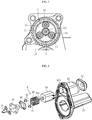
- FIG. 3 is an exploded perspective view of the electric actuator according to the present embodiment.
- FIG. 4 is a sectional view (a sectional view taken along A-A in FIG. 1 ) of a speed reduction mechanism included in the electric actuator according to the present embodiment
- FIG. 5 is an exploded perspective view of a lock mechanism included in the electric actuator according to the present embodiment.
- an electric actuator 1 of the present embodiment mainly includes an electric motor 2 as a drive source, a speed reduction mechanism 3 for decelerating rotation of the electric motor 2, a driving force transmission mechanism 4 for transmitting driving force decelerated by the speed reduction mechanism 3, a motion conversion mechanism 5 for converting rotary motion of the electric motor 2 transmitted by the driving force transmission mechanism 4 into linear motion, and a lock mechanism 6 for preventing the electric actuator 1 from being driven.
- the electric motor 2 is housed in a motor case 7.
- the motor case 7 is formed in a bottomed cylindrical shape, and a resin sealing member 8 for sealing a hole 7a is provided at a bottom thereof.
- the speed reduction mechanism 3 is a planetary gear speed reduction mechanism including a sun gear 9 connected to a rotating shaft 2a of the electric motor 2, a plurality of planetary gears 10 arranged around the sun gear 9, and the like.
- the speed reduction mechanism 3 includes the sun gear 9 as an input rotating body, a ring gear 11 as a raceway ring arranged on an outer periphery of the sun gear 9, the plurality of planetary gears 10 rotatably arranged between the sun gear 9 and the ring gear 11, and a carrier 12 as an output rotating body holding the planetary gears 10.
- the sun gear 9 is fixed to the rotating shaft 2a of the electric motor 2, and rotates integrally with the electric motor 2.
- Each planetary gear 10 is arranged between the sun gear 9 and the ring gear 11, and is assembled so as to mesh with them. Further, each planetary gear 10 is rotatably supported by a support shaft 13 provided on the carrier 12.
- the sun gear 9 of the speed reduction mechanism 3 rotates integrally therewith, and accordingly, the plurality of planetary gears 10 revolves along the ring gear 11 while rotating. Moreover, when the carrier 12 rotates with the revolution of the planetary gears 10, rotation of the electric motor 2 is decelerated and output.
- the speed reduction mechanism 3 is housed in a speed reduction mechanism case 14 connected to the motor case 7.
- a cylindrical motor adapter 15 as a motor support member for supporting the electric motor 2 is attached to the speed reduction mechanism case 14.
- the electric motor 2 is supported by inserting a projection 2b on an output side (a right side in FIG. 1 ) thereof into the motor adapter 15. Note that a portion of the electric motor 2 opposite to the output side is supported by an inner peripheral surface of the motor case 7.
- the driving force transmission mechanism 4 includes a driving side drive gear 16 to which driving force output from the speed reduction mechanism 3 is input and a driven side driven gear 17 that meshes with the drive gear 16.
- the driven gear 17 is constituted by a large-diameter gear having a larger number of teeth than the drive gear 16, and rotation is transmitted from the drive gear 16 to the driven gear 17 by decelerating the rotation.
- these gears 16, 17 may have the same number of teeth, and the rotation may be transmitted at a constant speed.
- a gear boss 18 is press-fitted and fixed.
- a cylinder 12a see FIG.
- the drive gear 16 and the driven gear 17 are accommodated in a transmission mechanism case 19 connected to the speed reduction mechanism case 14.
- the transmission mechanism case 19 is provided with a rolling bearing 52 that supports the one end side of the gear boss 18.
- another end of the gear boss 18 is supported by a rolling bearing 53 provided in a motion conversion mechanism case 25 described later.
- the motion conversion mechanism 5 is a ball screw mechanism 20 including a rotatable ball screw nut 21, a ball screw shaft 22 inserted on an inner peripheral side of the ball screw nut 21, a large number of balls 23 arranged between spiral grooves formed on an inner peripheral surface of the ball screw nut 21 and an outer peripheral surface of the ball screw shaft 22, and a circulation member 24 for circulating the balls 23 between the spiral grooves.
- the ball screw mechanism 20 is supported by the motion conversion mechanism case 25 connected to the transmission mechanism case 19.
- the ball screw nut 21 is rotatably supported by a bearing member 26 provided in the motion conversion mechanism case 25.
- the bearing member 26 is a double row angular contact ball bearing, but may be another bearing member.
- the driven gear 17 is integrally fixed to an outer peripheral surface of the ball screw nut 21.
- FIG. 1 shows a state in which the ball screw shaft 22 is arranged at an initial position where the ball screw shaft 22 is retreated most to the right in the drawing.
- a tip (a left end in FIG. 1 ) of the ball screw shaft 22 functions as an operation part 27 that operates a device to be used (not shown) as an operation target.
- a hole 22a for inserting a bolt or a pin for connecting a corresponding part of the device to be used (not shown) to the ball screw shaft 22 is provided on a tip side of the ball screw shaft 22.
- a rotation preventing pin 28 as a rotation restricting member for restricting rotation of the ball screw shaft 22 is provided on a rear end side of the ball screw shaft 22.
- the rear end side of the ball screw shaft 22 is covered with a screw shaft case 29 connected to the motion conversion mechanism case 25.
- a guide groove 29a extending in the axial direction is formed on an inner peripheral surface of the screw shaft case 29, and the rotation preventing pin 28 and a guide roller 30 provided on the rotation preventing pin 28 are inserted into the guide groove 29a.
- the guide roller 30 moves while rotating along the guide groove 29a, the ball screw shaft 22 moves forward or backward in the axial direction without rotating in a circumferential direction.
- a boot 31 for preventing foreign matter from entering the ball screw mechanism 20 or the electric actuator 1 is attached to the tip side of the ball screw shaft 22.
- the boot 31 is made of resin or rubber, and includes a large-diameter end 31a, a small-diameter end 31b, and a bellows 31c that connects them to expand and contract in the axial direction.
- the large-diameter end 31a is fastened and fixed to an outer peripheral surface of a cylinder 19a provided in the transmission mechanism case 19 by a boot band 32
- the small-diameter end 31b is fastened and fixed to the outer peripheral surface of the ball screw shaft 22 by a boot band 33.
- a boot cover 34 for protecting the outside of the boot 31 is provided integrally with the motor case 7.
- the lock mechanism 6 mainly includes a lock member 35, a slide screw nut 36, a slide screw shaft 37, a lock member fixing plate 38, a lock motor 39 as a lock drive source, and a spring 40.
- the lock member 35 is fastened to the slide screw nut 36 by bolts 41 via the lock member fixing plate 38.
- the lock motor 39 is housed in a holder 42 provided in the screw shaft case 29. Specifically, the lock motor 39 is inserted into the holder 42 from a side of the holder 42 where a cap member 43 is mounted (a right side of the holder 42 in FIG. 5 ), and the cap member 43 is mounted on the holder 42. As a result, the lock motor 39 is housed in the holder 42.
- a rotating shaft 39a of the lock motor 39 protrudes from a bottom 42a of the holder 42 (a portion opposite to the cap member 43 side) (see FIG. 1 ), and the slide screw shaft 37 is attached to the rotating shaft 39a.
- the spring 40 is disposed on an outer periphery of the slide screw shaft 37, and the slide screw nut 36 is screwed and mounted thereon.
- the spring 40 is axially compressed between the bottom 42a of the holder 42 and the lock member fixing plate 38.
- the lock member 35 is constantly urged in a forward direction (a left side in FIG. 1 ).
- the drive gear 16 is disposed in the forward direction of the lock member 35, and the drive gear 16 has an engagement hole 16a into which a tip of the lock member 35 can be inserted and engaged. Further, a plurality of the engagement holes 16a is provided in a circumferential direction of the drive gear 16.
- the lock member 35 is engaged with any one of the engagement holes 16a, thereby achieving a locked state in which rotation of the drive gear 16 is regulated and the forward and backward movement of the ball screw shaft 22 is regulated.
- FIG. 1 shows a locked state in which the tip of the lock member 35 is engaged with the engagement hole 16a of the drive gear 16.
- the slide screw shaft 37 rotates, so that the slide screw nut 36 and the lock member 35 attached thereto move backward.
- the tip of the lock member 35 is disengaged from the engagement hole 16a of the drive gear 16, and the locked state is released.
- the electric motor 2 is driven, and the operation part 27 (the ball screw shaft 22) is moved forward or backward, so that the operation target can be operated.
- the electric motor 2 is driven, energization of the lock motor 39 is continued, and the unlocked state is maintained.
- the electric actuator 1 includes a position detection device 44 for detecting an axial position of the operation part 27 (the ball screw shaft 22).
- the position detection device 44 includes a permanent magnet 45 as a sensor target provided on the ball screw shaft 22 (see FIG. 1 ) and magnetic sensors 46 as non-contact sensors housed in a sensor case 47 between the motor case 7 and the boot cover 34 (see FIG. 2 ).
- any type can be applied, and among them, a magnetic sensor such as a Hall IC or a linear Hall IC that can detect a direction and magnitude of a magnetic field using Hall effect is preferable.
- the magnetic sensors 46 are attached to a sensor base 48, and are housed in the sensor case 47 by fastening and fixing the sensor base 48 to the sensor case 47 with bolts 49.
- FIG. 6 which is a sectional view (a sectional view taken along a line B-B in FIG. 1 ) of the electric actuator 1 according to the present embodiment cut at positions of the magnetic sensors 46 and the permanent magnet 45, when the magnetic sensors 46 are housed in the sensor case 47 and the permanent magnet 45 is mounted on the ball screw shaft 22, the magnetic sensors 46 face the permanent magnet 45 via the boot 31 and the boot cover 34.
- the sensor base 48, the sensor case 47, and the boot cover 34 that cover peripheries of the magnetic sensors 46 are preferably formed of nonmagnetic material such as resin.
- a magnetic field at the positions where the magnetic sensors 46 are arranged also changes.
- a change in the magnetic field for example, a direction and strength of magnetic flux density
- FIGS. 7 and 8 the permanent magnet 45 is attached to the ball screw shaft 22 via an elastically deformable semi-cylindrical target holder 50.
- FIG. 7 shows a state before the target holder 50 is attached to the ball screw shaft 22
- FIG. 8 shows a state where the target holder 50 is attached to the ball screw shaft 22.
- the target holder 50 has one or more pairs (five pairs in an illustrated example) of fitting claws 50a.
- Each fitting claw 50a has a shape following the outer peripheral surface of the ball screw shaft 22, and when the target holder 50 is pushed into the ball screw shaft 22, each fitting claw 50a is elastically deformed in a direction away from each other and thereafter elastically returned. Accordingly, the target holder 50 is attached to the ball screw shaft 22.
- FIG. 9 is a sectional view of the state where the target holder 50 is attached to the ball screw shaft 22.
- a fitting recess 50b into which the permanent magnet 45 can be fitted is provided on an outer peripheral surface of the target holder 50.
- the fitting recess 50b has a pair of side walls 50c, and the side walls 50c are formed so as to approach each other toward tip sides thereof.
- a mounting surface 22c for mounting the permanent magnet 45 (via the target holder 50) is provided on an outer peripheral surface between a screw 22b and the operation part 27 of the ball screw shaft 22, a mounting surface 22c for mounting the permanent magnet 45 (via the target holder 50) is provided.
- the mounting surface 22c is formed by a flat surface 51 recessed in a radial direction from the outer peripheral surface of the ball screw shaft 22, and is arranged in parallel with an axis of the ball screw shaft 22.
- the mounting surface 22c is formed by recessing the outer peripheral surface of the ball screw shaft 22, it is possible to reduce an amount of radial projection when the permanent magnet 45 is mounted via the target holder 50. Therefore, a size of the electric actuator 1 can be suppressed.
- the mounting surface 22c is the flat surface 51
- a flat surface 50d inside the target holder 50 comes into contact with the flat surface 51 of the ball screw shaft 22 (see FIG. 9 ), thereby restricting rotation of the target holder 50 in the circumferential direction with respect to the ball screw shaft 22.
- the permanent magnet 45 is magnetized such that one of both ends in a longitudinal direction is an S pole and another is an N pole. If arrangement of the S pole and the N pole with respect to the ball screw shaft 22 differs for each electric actuator, an output signal of the magnetic sensors 46 that detect a magnetic field thereof changes, so that it is desirable that the S pole and the N pole are arranged in fixed directions. Therefore, in the present embodiment, in order to prevent erroneous assembly of the target holder 50 with respect to the mounting surface 22c, as shown in FIG. 7 , a recess 22d and a protrusion 50e for preventing erroneous assembly are provided at an axial one end of the mounting surface 22c and an axial one end of the target holder 50.
- the target holder 50 when the target holder 50 is in a direction shown in FIG. 7 , as shown in FIG. 8 , the target holder 50 can be mounted on the mounting surface 22c by fitting the protrusion 50e and the recess 22d.
- the protrusion 50e interferes with an edge of the mounting surface 22c, so that the mounting of the target holder 50 on the mounting surface 22c is hindered.
- the protrusion may be provided on the mounting surface 22c, and the recess may be provided on the target holder 50.
- the ball screw shaft 22 according to the present embodiment is different from the conventional screw shaft shown in FIG. 12 , and the flat surface 51 similar to the mounting surface 22c is also formed on a circumferential opposite side of the mounting surface 22c.
- These two flat surfaces 51 are formed at the same distance L from a symmetry axis M passing through an axis O of the ball screw shaft 22 (see FIG. 11 ), and are formed line-symmetric with each other with respect to the axis O (the symmetry axis M).
- a portion where the mounting surface 22c of the ball screw shaft 22 is formed has a non-circular, line-symmetric cross section.
- the distance L from the symmetry axis M to each flat surface 51 includes not only the completely same distance but also a case where there is an allowable design error of about ⁇ 1 mm (substantially the same).
- the cross section of the portion where the mounting surface 22c of the ball screw shaft 22 is formed may be a quadrangular cross section or a cross section of a polygon such as a regular octagon.
- the portion where the mounting surface 22c is formed has a line-symmetric cross section having the two flat surfaces 51, even if this portion is formed by cutting processing, a warp of the ball screw shaft 22 due to the processing can be suppressed.
- the two flat surfaces 51 by cutting a circular cross section of the ball screw shaft 22 even if a warp occurs due to cutting resistance or heat during the processing, warps that occur on the one flat surface 51 side and the other flat surface 51 occur to the same extent in directions opposite to each other.
- the warps that occur on the one flat surface 51 side and the other flat surface 51 side are offset each other, and a warp that finally occurs on the ball screw shaft 22 can be suppressed.
- linearity (straightness) of the ball screw shaft 22 can be improved, and occurrence of misalignment between the ball screw shaft 22 and the ball screw nut 21 due to the warp can be suppressed.
- the highly reliable ball screw mechanism and electric actuator can be provided.
- the cross-sectional shape is line-symmetric, it is possible to suppress occurrence of a warp due to heat treatment.
- the cross-sectional shape is line-symmetric, an amount of shrinkage of the ball screw shaft 22 due to the heat treatment becomes uniform, so that occurrence of a warp due to a difference in amount of shrinkage can be suppressed.
- heat treatment such as induction hardening or vacuum carburizing is performed on at least the portion where the mounting surface 22c is formed in order to improve strength, occurrence of a warp is suppressed. Therefore, it is possible to provide the ball screw shaft 22 having high shaft linearity (straightness) while securing required strength.
- the ball screw shaft 22 since the ball screw shaft 22 according to the present embodiment has the two flat surfaces 51, an operator can select one of the flat surfaces 51 to mount the target holder 50, thereby also improving a degree of freedom (flexibility) in mounting.
- the above-described recess or protrusion for preventing erroneous assembly on both the flat surfaces 51 it is possible to prevent erroneous assembly in attaching the target holder 50 to either of the flat surfaces 51.
- the mounting surface 22c to which the target holder 50 is mounted is formed by the one flat surface 51, but the mounting surface 22c may be a surface obtained by combining a plurality of flat surfaces or curved surfaces. Even with such a mounting surface 22c, it is possible to suppress occurrence of a warp of the ball screw shaft 22 by forming the surfaces so as to be line-symmetric with each other.
- the feed screw mechanism according to the present invention is not limited to the ball screw mechanism, and may be a slide screw mechanism in which a screw shaft is screwed to a nut without using a ball.
- the electric actuator according to the present invention is not limited to the electric motor according to the above-described embodiment which converts the rotary motion of the electric motor into the linear motion parallel to the rotation axis thereof, but may be an electric motor which converts the rotary motion of the electric motor into linear motion coaxial to the rotation axis thereof.
Landscapes
- Engineering & Computer Science (AREA)
- General Engineering & Computer Science (AREA)
- Mechanical Engineering (AREA)
- Power Engineering (AREA)
- Microelectronics & Electronic Packaging (AREA)
- Transmission Devices (AREA)
- Connection Of Motors, Electrical Generators, Mechanical Devices, And The Like (AREA)
Abstract
Description
- The present invention relates to a screw shaft that constitutes a feed screw mechanism, a feed screw mechanism, and an electric actuator.
- As an electric actuator used for an automatic transmission mechanism, a brake mechanism, a steering mechanism, and the like of an automobile, an actuator using a feed screw mechanism that converts rotary motion of an electric motor into linear motion is known.
- In this type of electric actuator, it is important to control a movement amount (an axial position) of a movable part that performs linear motion. Therefore, for example, in
Patent Literature 1 below, an electric actuator in which a permanent magnet as a sensor target is attached to a screw shaft of a ball screw mechanism, and a magnetic field of the permanent magnet that changes with axial movement of the screw shaft is detected by a magnetic sensor, thereby acquiring an axial movement amount (position) of the screw shaft has been proposed. - Patent Literature 1:
JP 2017-180681 A - In the electric actuator described in
Patent Literature 1, a cut-away part is formed on an outer peripheral surface of the screw shaft in order to attach the permanent magnet to the screw shaft. - However, when the outer peripheral surface of the screw shaft is subjected to cutting processing in forming the cut-away part, as shown in
FIG. 12 , a warp in which an axis O of ascrew shaft 100 is bent to a cut-awaypart 100a side occurs due to cutting resistance or heat during the processing. In particular, the occurrence of such a warp tends to be noticeable because, in a case where an axial movement distance of the screw shaft is long, the permanent magnet needs to be arranged long in an axial direction, that is, the cut-away part needs to be formed long in the axial direction. Moreover, when the screw shaft is warped, in a case where a mating member to be operated is connected to a tip of the screw shaft, the screw shaft is constrained at this connection position, and a screw groove side opposite to the tip of the screw shaft is tilted. As a result, misalignment occurs between the screw shaft and a nut, which may lead to a malfunction, reduction in operation efficiency, and reduction in a service life of a feed screw mechanism. Therefore, improvement is desired. - Therefore, an object of the present invention is to provide a screw shaft capable of suppressing occurrence of a warp, a feed screw mechanism including such a screw shaft, and an electric actuator.
- In order to solve the above problems, the present invention is a screw shaft that constitutes a feed screw mechanism provided in an electric actuator, the screw shaft having a mounting surface for mounting a sensor target, wherein a portion where the mounting surface is formed has a non-circular, line-symmetric cross section.
- In this way, by making the portion where the mounting surface is formed into the non-circular, line-symmetric cross section, even if a warp occurs due to cutting resistance or heat when the mounting surface is formed, the warp will occur to the same extent on one side and another side of the line-symmetric cross section of the screw shaft. In addition, since the warps that occur on the one side and the other side occur in directions opposite to each other, these warps are offset, and a warp that finally occurs on the screw shaft can be suppressed.
- Alternatively, two flat surfaces may be formed so as to be line-symmetric with respect to an axis of the screw shaft, and one of the two flat surfaces may be the mounting surface. Furthermore, by allowing the mounting surface to be arbitrarily selectable from the two flat surfaces, a degree of freedom (flexibility) in mounting the sensor target is improved.
- Further, the mounting surface may be a surface on which a target holder that holds the sensor target is mounted. In this case, by providing a protrusion or a recess for preventing erroneous assembly of the target holder with respect to the mounting surface at axial one end of the mounting surface, the sensor target can be correctly mounted and reliability is improved.
- Further, at least the portion where the mounting surface is formed of the screw shaft may be heat-treated. Since a cross-sectional shape of the screw shaft is line-symmetric, it is possible to suppress occurrence of a warp due to the heat treatment. In other words, since the cross-sectional shape is line-symmetric, an amount of shrinkage of the screw shaft due to the heat treatment becomes uniform, so that occurrence of a warp due to a difference in amount of shrinkage can be suppressed. This makes it possible to provide a screw shaft having high shaft linearity (straightness) while securing necessary strength.
- Further, the screw shaft according to the present invention can be applied to a feed screw mechanism provided in an electric actuator including: a rotatable nut; and a screw shaft that moves in an axial direction with rotation of the nut.
- Furthermore, the screw shaft according to the present invention is also applicable to an electric actuator including: an electric motor; and a feed screw mechanism that converts rotary motion of the electric motor into linear motion.
- According to the present invention, since a warp of a screw shaft can be suppressed, a malfunction, reduction in operation efficiency, and further, reduction in a service life of a feed screw mechanism resulting from the warp of the screw shaft can be avoided. A highly reliable feed screw mechanism and an electric actuator including the same can be provided.
-
-
FIG. 1 is a longitudinal sectional view of an electric actuator showing an embodiment of the present invention. -
FIG. 2 is an external perspective view of the electric actuator according to the present embodiment. -
FIG. 3 is an exploded perspective view of the electric actuator according to the present embodiment. -
FIG. 4 is a sectional view (a sectional view taken along A-A inFIG. 1 ) of a speed reduction mechanism included in the electric actuator according to the present embodiment. -
FIG. 5 is an exploded perspective view of a lock mechanism included in the electric actuator according to the present embodiment. -
FIG. 6 is a sectional view (a sectional view taken along a line B-B inFIG. 1 ) of the electric actuator according to the present embodiment, which is cut at positions of magnetic sensors and a permanent magnet. -
FIG. 7 is a perspective view showing a state before a target holder is attached to a ball screw shaft. -
FIG. 8 is a perspective view showing a state where the target holder is attached to the ball screw shaft. -
FIG. 9 is a sectional view of the state where the target holder is attached to the ball screw shaft. -
FIG. 10 is a side view of the ball screw shaft according to the present embodiment. -
FIG. 11 is a sectional view (a sectional view taken along C-C ofFIG. 10 ) of the ball screw shaft according to the present embodiment. -
FIG. 12 is a view for explaining problems in a conventional screw shaft. - Hereinafter, the present invention will be described with reference to the accompanying drawings. Note that, in each of the drawings for describing the present invention, constituent elements such as members and components having the same function or shape are denoted by the same reference numerals as much as possible, and once described, description thereof is omitted.
-
FIG. 1 is a longitudinal sectional view of an electric actuator showing an embodiment of the present invention,FIG. 2 is an external perspective view of the electric actuator according to the present embodiment, andFIG. 3 is an exploded perspective view of the electric actuator according to the present embodiment. Further,FIG. 4 is a sectional view (a sectional view taken along A-A inFIG. 1 ) of a speed reduction mechanism included in the electric actuator according to the present embodiment, andFIG. 5 is an exploded perspective view of a lock mechanism included in the electric actuator according to the present embodiment. - As shown in
FIG. 1 , anelectric actuator 1 of the present embodiment mainly includes anelectric motor 2 as a drive source, aspeed reduction mechanism 3 for decelerating rotation of theelectric motor 2, a drivingforce transmission mechanism 4 for transmitting driving force decelerated by thespeed reduction mechanism 3, amotion conversion mechanism 5 for converting rotary motion of theelectric motor 2 transmitted by the drivingforce transmission mechanism 4 into linear motion, and alock mechanism 6 for preventing theelectric actuator 1 from being driven. - The
electric motor 2 is housed in amotor case 7. Themotor case 7 is formed in a bottomed cylindrical shape, and aresin sealing member 8 for sealing ahole 7a is provided at a bottom thereof. - The
speed reduction mechanism 3 is a planetary gear speed reduction mechanism including asun gear 9 connected to a rotatingshaft 2a of theelectric motor 2, a plurality ofplanetary gears 10 arranged around thesun gear 9, and the like. - As shown in
FIG. 4 , thespeed reduction mechanism 3 includes thesun gear 9 as an input rotating body, aring gear 11 as a raceway ring arranged on an outer periphery of thesun gear 9, the plurality ofplanetary gears 10 rotatably arranged between thesun gear 9 and thering gear 11, and acarrier 12 as an output rotating body holding theplanetary gears 10. - The
sun gear 9 is fixed to the rotatingshaft 2a of theelectric motor 2, and rotates integrally with theelectric motor 2. Eachplanetary gear 10 is arranged between thesun gear 9 and thering gear 11, and is assembled so as to mesh with them. Further, eachplanetary gear 10 is rotatably supported by asupport shaft 13 provided on thecarrier 12. - When the
electric motor 2 starts driving, thesun gear 9 of thespeed reduction mechanism 3 rotates integrally therewith, and accordingly, the plurality ofplanetary gears 10 revolves along thering gear 11 while rotating. Moreover, when thecarrier 12 rotates with the revolution of theplanetary gears 10, rotation of theelectric motor 2 is decelerated and output. - Further, as shown in
FIGS. 1 and3 , thespeed reduction mechanism 3 is housed in a speedreduction mechanism case 14 connected to themotor case 7. Acylindrical motor adapter 15 as a motor support member for supporting theelectric motor 2 is attached to the speedreduction mechanism case 14. Theelectric motor 2 is supported by inserting aprojection 2b on an output side (a right side inFIG. 1 ) thereof into themotor adapter 15. Note that a portion of theelectric motor 2 opposite to the output side is supported by an inner peripheral surface of themotor case 7. - As shown in
FIGS. 1 and3 , the drivingforce transmission mechanism 4 includes a drivingside drive gear 16 to which driving force output from thespeed reduction mechanism 3 is input and a driven side drivengear 17 that meshes with thedrive gear 16. In the present embodiment, the drivengear 17 is constituted by a large-diameter gear having a larger number of teeth than thedrive gear 16, and rotation is transmitted from thedrive gear 16 to the drivengear 17 by decelerating the rotation. However, thesegears drive gear 16, agear boss 18 is press-fitted and fixed. Acylinder 12a (seeFIG. 1 ) of thecarrier 12 of thespeed reduction mechanism 3 is press-fitted into one end side of thegear boss 18 so that thecarrier 12 and thedrive gear 16 rotate integrally. Thus, rotary motion decelerated by thespeed reduction mechanism 3 is transmitted from thecarrier 12 to thedrive gear 16. - Further, the
drive gear 16 and the drivengear 17 are accommodated in atransmission mechanism case 19 connected to the speedreduction mechanism case 14. Thetransmission mechanism case 19 is provided with a rollingbearing 52 that supports the one end side of thegear boss 18. On the other hand, another end of thegear boss 18 is supported by a rollingbearing 53 provided in a motionconversion mechanism case 25 described later. - The
motion conversion mechanism 5 is aball screw mechanism 20 including a rotatableball screw nut 21, aball screw shaft 22 inserted on an inner peripheral side of theball screw nut 21, a large number ofballs 23 arranged between spiral grooves formed on an inner peripheral surface of theball screw nut 21 and an outer peripheral surface of theball screw shaft 22, and acirculation member 24 for circulating theballs 23 between the spiral grooves. Theball screw mechanism 20 is supported by the motionconversion mechanism case 25 connected to thetransmission mechanism case 19. Specifically, theball screw nut 21 is rotatably supported by a bearingmember 26 provided in the motionconversion mechanism case 25. In the present embodiment, the bearingmember 26 is a double row angular contact ball bearing, but may be another bearing member. Also, the drivengear 17 is integrally fixed to an outer peripheral surface of theball screw nut 21. - Therefore, when driving force of the
electric motor 2 is transmitted from thedrive gear 16 to the drivengear 17 via thespeed reduction mechanism 3, the drivengear 17 rotates, and theball screw nut 21 also rotates integrally therewith. Then, when theball screw nut 21 rotates, the large number ofballs 23 circulate and move along both the spiral grooves, and theball screw shaft 22 linearly moves in an axial direction thereof, whereby rotary motion of theelectric motor 2 is converted into linear motion. Further, when theelectric motor 2 rotates in a forward or reverse direction, theball screw nut 21 rotates in the forward or reverse direction, and theball screw shaft 22 moves forward or backward in the axial direction. Note thatFIG. 1 shows a state in which theball screw shaft 22 is arranged at an initial position where theball screw shaft 22 is retreated most to the right in the drawing. - In addition, a tip (a left end in
FIG. 1 ) of theball screw shaft 22 functions as anoperation part 27 that operates a device to be used (not shown) as an operation target. In the present embodiment, ahole 22a for inserting a bolt or a pin for connecting a corresponding part of the device to be used (not shown) to theball screw shaft 22 is provided on a tip side of theball screw shaft 22. On the other hand, on a rear end side of theball screw shaft 22, arotation preventing pin 28 as a rotation restricting member for restricting rotation of theball screw shaft 22 is provided. Further, the rear end side of theball screw shaft 22 is covered with ascrew shaft case 29 connected to the motionconversion mechanism case 25. Aguide groove 29a extending in the axial direction is formed on an inner peripheral surface of thescrew shaft case 29, and therotation preventing pin 28 and aguide roller 30 provided on therotation preventing pin 28 are inserted into theguide groove 29a. As theguide roller 30 moves while rotating along theguide groove 29a, theball screw shaft 22 moves forward or backward in the axial direction without rotating in a circumferential direction. - Further, a
boot 31 for preventing foreign matter from entering theball screw mechanism 20 or theelectric actuator 1 is attached to the tip side of theball screw shaft 22. Theboot 31 is made of resin or rubber, and includes a large-diameter end 31a, a small-diameter end 31b, and abellows 31c that connects them to expand and contract in the axial direction. The large-diameter end 31a is fastened and fixed to an outer peripheral surface of acylinder 19a provided in thetransmission mechanism case 19 by aboot band 32, and the small-diameter end 31b is fastened and fixed to the outer peripheral surface of theball screw shaft 22 by aboot band 33. Further, aboot cover 34 for protecting the outside of theboot 31 is provided integrally with themotor case 7. - As shown in
FIG. 5 , thelock mechanism 6 mainly includes alock member 35, aslide screw nut 36, aslide screw shaft 37, a lockmember fixing plate 38, alock motor 39 as a lock drive source, and aspring 40. Thelock member 35 is fastened to theslide screw nut 36 bybolts 41 via the lockmember fixing plate 38. Thelock motor 39 is housed in aholder 42 provided in thescrew shaft case 29. Specifically, thelock motor 39 is inserted into theholder 42 from a side of theholder 42 where acap member 43 is mounted (a right side of theholder 42 inFIG. 5 ), and thecap member 43 is mounted on theholder 42. As a result, thelock motor 39 is housed in theholder 42. When thelock motor 39 is housed in theholder 42, arotating shaft 39a of thelock motor 39 protrudes from a bottom 42a of the holder 42 (a portion opposite to thecap member 43 side) (seeFIG. 1 ), and theslide screw shaft 37 is attached to therotating shaft 39a. Further, thespring 40 is disposed on an outer periphery of theslide screw shaft 37, and theslide screw nut 36 is screwed and mounted thereon. - As shown in
FIG. 1 , thespring 40 is axially compressed between the bottom 42a of theholder 42 and the lockmember fixing plate 38. By urging force of thecompressed spring 40, thelock member 35 is constantly urged in a forward direction (a left side inFIG. 1 ). Thedrive gear 16 is disposed in the forward direction of thelock member 35, and thedrive gear 16 has anengagement hole 16a into which a tip of thelock member 35 can be inserted and engaged. Further, a plurality of theengagement holes 16a is provided in a circumferential direction of thedrive gear 16. Thelock member 35 is engaged with any one of theengagement holes 16a, thereby achieving a locked state in which rotation of thedrive gear 16 is regulated and the forward and backward movement of theball screw shaft 22 is regulated. -
FIG. 1 shows a locked state in which the tip of thelock member 35 is engaged with theengagement hole 16a of thedrive gear 16. In this state, when power is supplied to thelock motor 39 and thelock motor 39 is driven, theslide screw shaft 37 rotates, so that theslide screw nut 36 and thelock member 35 attached thereto move backward. As a result, the tip of thelock member 35 is disengaged from theengagement hole 16a of thedrive gear 16, and the locked state is released. When the locked state is released, theelectric motor 2 is driven, and the operation part 27 (the ball screw shaft 22) is moved forward or backward, so that the operation target can be operated. In addition, while theelectric motor 2 is driven, energization of thelock motor 39 is continued, and the unlocked state is maintained. - Thereafter, when power supply to the
electric motor 2 is cut off and the forward or backward movement of the operation part 27 (the ball screw shaft 22) is stopped, the power supply to thelock motor 39 is also cut off at the same time, and thelock member 35 is pushed and moved in the forward direction by the urging force of thespring 40. As a result, the tip of thelock member 35 engages with theengagement hole 16a of thedrive gear 16, and a locked state is established. As described above, since the forward and backward movement of the operation part 27 (the ball screw shaft 22) is restricted by being in the locked state, even when external force is input from the operation target side to the operation part 27 (the ball screw shaft 22) side, it is possible to prevent the operation part 27 (the ball screw shaft 22) from moving in the axial direction and to keep theoperation part 27 at a predetermined position. - Further, the
electric actuator 1 according to the present embodiment includes aposition detection device 44 for detecting an axial position of the operation part 27 (the ball screw shaft 22). Theposition detection device 44 includes apermanent magnet 45 as a sensor target provided on the ball screw shaft 22 (seeFIG. 1 ) andmagnetic sensors 46 as non-contact sensors housed in asensor case 47 between themotor case 7 and the boot cover 34 (seeFIG. 2 ). - As the
magnetic sensor 46, any type can be applied, and among them, a magnetic sensor such as a Hall IC or a linear Hall IC that can detect a direction and magnitude of a magnetic field using Hall effect is preferable. Themagnetic sensors 46 are attached to asensor base 48, and are housed in thesensor case 47 by fastening and fixing thesensor base 48 to thesensor case 47 withbolts 49. - As shown in
FIG. 6 , which is a sectional view (a sectional view taken along a line B-B inFIG. 1 ) of theelectric actuator 1 according to the present embodiment cut at positions of themagnetic sensors 46 and thepermanent magnet 45, when themagnetic sensors 46 are housed in thesensor case 47 and thepermanent magnet 45 is mounted on theball screw shaft 22, themagnetic sensors 46 face thepermanent magnet 45 via theboot 31 and theboot cover 34. Note that thesensor base 48, thesensor case 47, and theboot cover 34 that cover peripheries of themagnetic sensors 46 are preferably formed of nonmagnetic material such as resin. - In the
position detection device 44 configured as described above, when theball screw shaft 22 moves forward and backward, as the position of thepermanent magnet 45 with respect to themagnetic sensors 46 changes, a magnetic field at the positions where themagnetic sensors 46 are arranged also changes. By detecting a change in the magnetic field (for example, a direction and strength of magnetic flux density) at this time by themagnetic sensors 46, an axial position of thepermanent magnet 45 and thus the axial position of the operation part 27 (the ball screw shaft 22) can be obtained. - Further, as shown in
FIGS. 7 and8 , thepermanent magnet 45 is attached to theball screw shaft 22 via an elastically deformablesemi-cylindrical target holder 50.FIG. 7 shows a state before thetarget holder 50 is attached to theball screw shaft 22, andFIG. 8 shows a state where thetarget holder 50 is attached to theball screw shaft 22. - As shown in
FIGS. 7 and8 , thetarget holder 50 has one or more pairs (five pairs in an illustrated example) offitting claws 50a. Eachfitting claw 50a has a shape following the outer peripheral surface of theball screw shaft 22, and when thetarget holder 50 is pushed into theball screw shaft 22, eachfitting claw 50a is elastically deformed in a direction away from each other and thereafter elastically returned. Accordingly, thetarget holder 50 is attached to theball screw shaft 22. -
FIG. 9 is a sectional view of the state where thetarget holder 50 is attached to theball screw shaft 22. - As shown in
FIG. 9 , on an outer peripheral surface of thetarget holder 50, afitting recess 50b into which thepermanent magnet 45 can be fitted is provided. Thefitting recess 50b has a pair ofside walls 50c, and theside walls 50c are formed so as to approach each other toward tip sides thereof. As a result, when thepermanent magnet 45 is pushed and fitted into thefitting recess 50b, thepermanent magnet 45 is sandwiched between the pair ofside walls 50c, thereby preventing thepermanent magnet 45 from being detached from thefitting recess 50b. - Also, as shown in
FIG. 7 , on an outer peripheral surface between ascrew 22b and theoperation part 27 of theball screw shaft 22, a mountingsurface 22c for mounting the permanent magnet 45 (via the target holder 50) is provided. The mountingsurface 22c is formed by aflat surface 51 recessed in a radial direction from the outer peripheral surface of theball screw shaft 22, and is arranged in parallel with an axis of theball screw shaft 22. As described above, since the mountingsurface 22c is formed by recessing the outer peripheral surface of theball screw shaft 22, it is possible to reduce an amount of radial projection when thepermanent magnet 45 is mounted via thetarget holder 50. Therefore, a size of theelectric actuator 1 can be suppressed. Further, since the mountingsurface 22c is theflat surface 51, when thetarget holder 50 is mounted on theball screw shaft 22, aflat surface 50d inside thetarget holder 50 comes into contact with theflat surface 51 of the ball screw shaft 22 (seeFIG. 9 ), thereby restricting rotation of thetarget holder 50 in the circumferential direction with respect to theball screw shaft 22. - The
permanent magnet 45 is magnetized such that one of both ends in a longitudinal direction is an S pole and another is an N pole. If arrangement of the S pole and the N pole with respect to theball screw shaft 22 differs for each electric actuator, an output signal of themagnetic sensors 46 that detect a magnetic field thereof changes, so that it is desirable that the S pole and the N pole are arranged in fixed directions. Therefore, in the present embodiment, in order to prevent erroneous assembly of thetarget holder 50 with respect to the mountingsurface 22c, as shown inFIG. 7 , arecess 22d and aprotrusion 50e for preventing erroneous assembly are provided at an axial one end of the mountingsurface 22c and an axial one end of thetarget holder 50. In other words, when thetarget holder 50 is in a direction shown inFIG. 7 , as shown inFIG. 8 , thetarget holder 50 can be mounted on the mountingsurface 22c by fitting theprotrusion 50e and therecess 22d. However, when thetarget holder 50 is in a direction opposite to the direction shown inFIG. 7 , theprotrusion 50e interferes with an edge of the mountingsurface 22c, so that the mounting of thetarget holder 50 on the mountingsurface 22c is hindered. In this way, by enabling mounting only when thetarget holder 50 is in the predetermined direction with respect to the mountingsurface 22c, erroneous assembly in which thepermanent magnet 45 is mounted in the direction opposite to the predetermined direction can be prevented. Note that, contrary to the present embodiment, the protrusion may be provided on the mountingsurface 22c, and the recess may be provided on thetarget holder 50. - Here, as shown in
FIG. 10 andFIG. 11 , which is a sectional view taken along C-C ofFIG. 10 , theball screw shaft 22 according to the present embodiment is different from the conventional screw shaft shown inFIG. 12 , and theflat surface 51 similar to the mountingsurface 22c is also formed on a circumferential opposite side of the mountingsurface 22c. These twoflat surfaces 51 are formed at the same distance L from a symmetry axis M passing through an axis O of the ball screw shaft 22 (seeFIG. 11 ), and are formed line-symmetric with each other with respect to the axis O (the symmetry axis M). In other words, since the twoflat surfaces 51 that are line-symmetric with each other are provided, a portion where the mountingsurface 22c of theball screw shaft 22 is formed has a non-circular, line-symmetric cross section. Note that the distance L from the symmetry axis M to eachflat surface 51 includes not only the completely same distance but also a case where there is an allowable design error of about ±1 mm (substantially the same). Further, the cross section of the portion where the mountingsurface 22c of theball screw shaft 22 is formed may be a quadrangular cross section or a cross section of a polygon such as a regular octagon. - As described above, in the
ball screw shaft 22 according to the present embodiment, since the portion where the mountingsurface 22c is formed has a line-symmetric cross section having the twoflat surfaces 51, even if this portion is formed by cutting processing, a warp of theball screw shaft 22 due to the processing can be suppressed. In other words, in forming the twoflat surfaces 51 by cutting a circular cross section of theball screw shaft 22, even if a warp occurs due to cutting resistance or heat during the processing, warps that occur on the oneflat surface 51 side and the otherflat surface 51 occur to the same extent in directions opposite to each other. For this reason, the warps that occur on the oneflat surface 51 side and the otherflat surface 51 side are offset each other, and a warp that finally occurs on theball screw shaft 22 can be suppressed. As a result, linearity (straightness) of theball screw shaft 22 can be improved, and occurrence of misalignment between theball screw shaft 22 and theball screw nut 21 due to the warp can be suppressed. As a result, it is possible to avoid a malfunction, reduction in operation efficiency, and reduction in a life of the ball screw mechanism. The highly reliable ball screw mechanism and electric actuator can be provided. - Further, in the
ball screw shaft 22 according to the present embodiment, since the cross-sectional shape is line-symmetric, it is possible to suppress occurrence of a warp due to heat treatment. In other words, since the cross-sectional shape is line-symmetric, an amount of shrinkage of theball screw shaft 22 due to the heat treatment becomes uniform, so that occurrence of a warp due to a difference in amount of shrinkage can be suppressed. As a result, even if heat treatment such as induction hardening or vacuum carburizing is performed on at least the portion where the mountingsurface 22c is formed in order to improve strength, occurrence of a warp is suppressed. Therefore, it is possible to provide theball screw shaft 22 having high shaft linearity (straightness) while securing required strength. - Further, since the
ball screw shaft 22 according to the present embodiment has the twoflat surfaces 51, an operator can select one of theflat surfaces 51 to mount thetarget holder 50, thereby also improving a degree of freedom (flexibility) in mounting. In addition, by providing the above-described recess or protrusion for preventing erroneous assembly on both theflat surfaces 51, it is possible to prevent erroneous assembly in attaching thetarget holder 50 to either of the flat surfaces 51. - The embodiment of the present invention has been described above, but the present invention is not limited to the above-described embodiment. It is needless to say that the present invention can be embodied in various forms without departing from the gist of the present invention.
- In the above-described embodiment, the mounting
surface 22c to which thetarget holder 50 is mounted is formed by the oneflat surface 51, but the mountingsurface 22c may be a surface obtained by combining a plurality of flat surfaces or curved surfaces. Even with such a mountingsurface 22c, it is possible to suppress occurrence of a warp of theball screw shaft 22 by forming the surfaces so as to be line-symmetric with each other. - Further, in the above-described embodiment, an example in which the present invention is applied to the
ball screw shaft 22 has been described. However, the feed screw mechanism according to the present invention is not limited to the ball screw mechanism, and may be a slide screw mechanism in which a screw shaft is screwed to a nut without using a ball. - Further, the electric actuator according to the present invention is not limited to the electric motor according to the above-described embodiment which converts the rotary motion of the electric motor into the linear motion parallel to the rotation axis thereof, but may be an electric motor which converts the rotary motion of the electric motor into linear motion coaxial to the rotation axis thereof.
-
- 1
- electric actuator
- 2
- electric motor
- 20
- ball screw mechanism
- 21
- ball screw nut
- 22
- ball screw shaft
- 22c
- mounting surface
- 22d
- recess
- 44
- position detection device
- 45
- permanent magnet
- 46
- magnetic sensor
- 50
- target holder
- 50e
- protrusion
- 51
- flat surface
- O
- axis
Claims (7)
- A screw shaft that constitutes a feed screw mechanism provided in an electric actuator, the screw shaft having a mounting surface for mounting a sensor target, wherein a portion where the mounting surface is formed has a non-circular, line-symmetric cross section.
- The screw shaft according to claim 1, wherein two flat surfaces are formed so as to be line-symmetric with respect to an axis, and one of the two flat surfaces is the mounting surface.
- The screw shaft according to claim 2, wherein the flat surface serving as the mounting surface can be arbitrarily selected from the two flat surfaces.
- The screw shaft according to any one of claims 1 to 3, wherein
the mounting surface is a surface on which a target holder that holds the sensor target is mounted, and
a protrusion or a recess for preventing erroneous assembly of the target holder with respect to the mounting surface is provided at axial one end of the mounting surface. - The screw shaft according to any one of claims 1 to 4, wherein at least the portion where the mounting surface is formed is heat-treated.
- A feed screw mechanism provided in an electric actuator, the feed screw mechanism comprising:a rotatable nut; anda screw shaft that moves in an axial direction with rotation of the nut,wherein the screw shaft according to any one of claims 1 to 5 is used as the screw shaft.
- An electric actuator comprising:an electric motor; anda feed screw mechanism that converts rotary motion of the electric motor into linear motion,wherein the screw shaft according to any one of claims 1 to 5 is used as a screw shaft constituting the feed screw mechanism.
Applications Claiming Priority (2)
| Application Number | Priority Date | Filing Date | Title |
|---|---|---|---|
| JP2018033201A JP2019148299A (en) | 2018-02-27 | 2018-02-27 | Screw shaft, feed screw mechanism and electric actuator |
| PCT/JP2019/007377 WO2019167964A1 (en) | 2018-02-27 | 2019-02-26 | Screw shaft, feed screw mechanism, and electric actuator |
Publications (3)
| Publication Number | Publication Date |
|---|---|
| EP3760898A1 true EP3760898A1 (en) | 2021-01-06 |
| EP3760898A4 EP3760898A4 (en) | 2021-11-03 |
| EP3760898B1 EP3760898B1 (en) | 2023-04-05 |
Family
ID=67805020
Family Applications (1)
| Application Number | Title | Priority Date | Filing Date |
|---|---|---|---|
| EP19761296.3A Active EP3760898B1 (en) | 2018-02-27 | 2019-02-26 | Screw shaft, feed screw mechanism, and electric actuator |
Country Status (5)
| Country | Link |
|---|---|
| US (1) | US11204081B2 (en) |
| EP (1) | EP3760898B1 (en) |
| JP (1) | JP2019148299A (en) |
| CN (1) | CN111742163B (en) |
| WO (1) | WO2019167964A1 (en) |
Families Citing this family (8)
| Publication number | Priority date | Publication date | Assignee | Title |
|---|---|---|---|---|
| CA2953949C (en) * | 2014-06-30 | 2023-03-28 | Schlumberger Canada Limited | Compact articulation mechanism |
| JP2019148299A (en) * | 2018-02-27 | 2019-09-05 | Ntn株式会社 | Screw shaft, feed screw mechanism and electric actuator |
| JP2021010269A (en) * | 2019-07-02 | 2021-01-28 | 本田技研工業株式会社 | Drive unit and vehicle |
| US11365790B2 (en) * | 2019-07-16 | 2022-06-21 | Hiwin Technologies Corp. | Linear actuator and method for identifying the same |
| US20210394818A1 (en) * | 2020-06-22 | 2021-12-23 | Schaeffler Technologies AG & Co. KG | Steering mechanism for autonomous vehicle |
| KR102562497B1 (en) * | 2021-04-01 | 2023-08-02 | 국방과학연구소 | Load simulator for testing actuator |
| US11616416B2 (en) * | 2021-05-05 | 2023-03-28 | Nidec Motor Corporation | Electric linear actuator with optimized coupling |
| CN121605254A (en) * | 2023-07-28 | 2026-03-03 | 捷太格特轴承北美有限公司 | Screw actuator with integrated sensing capability |
Family Cites Families (26)
| Publication number | Priority date | Publication date | Assignee | Title |
|---|---|---|---|---|
| JPS5441882Y2 (en) * | 1974-08-03 | 1979-12-06 | ||
| JPS5121053A (en) | 1974-08-13 | 1976-02-19 | Fuji Keisotsuki Seisakusho Kk | Tatewarino onejio kumiawaseta chosetsuneji |
| US4398109A (en) * | 1979-12-29 | 1983-08-09 | Kabushiki Kaisha Tokai Rika Denki Seisakusho | Electric motor |
| US5704250A (en) * | 1996-04-04 | 1998-01-06 | Western Atlas, Inc. | Ball screw drive with dynamically adjustable preload |
| WO2006107938A2 (en) * | 2005-04-04 | 2006-10-12 | Danaher Motion, L.L.C. | Linear motion assembly with monitoring system and method of monitoring |
| US7095198B1 (en) * | 2005-06-16 | 2006-08-22 | Honeywell International Inc. | Speed sensor for a power sensor module |
| JP5480187B2 (en) * | 2011-03-25 | 2014-04-23 | 勝彦 横井 | Indexing device |
| US8791663B2 (en) * | 2012-10-19 | 2014-07-29 | Robotzone, Llc | Hobby servo motor linear actuator systems |
| JP2014105810A (en) * | 2012-11-29 | 2014-06-09 | Nsk Ltd | Linear guide device |
| JP6224349B2 (en) * | 2013-05-15 | 2017-11-01 | 株式会社アイエイアイ | Stepping motor control system and stepping motor control method |
| JP6349627B2 (en) * | 2013-05-29 | 2018-07-04 | アイシン精機株式会社 | Displacement detection device for linear motion mechanism, and rear wheel steering device for vehicle equipped with the device |
| EP2816321B1 (en) | 2013-05-29 | 2018-05-23 | Aisin Seiki Kabushiki Kaisha | Displacement detection apparatus for linear motion mechanism and rear wheel steering apparatus for vehicle including the same |
| FR3006379B1 (en) * | 2013-06-04 | 2015-06-19 | Sagem Defense Securite | ACTUATING DEVICE FOR MOVING A MOBILE HOOD FROM A THRUST INVERTER |
| JP5746266B2 (en) * | 2013-06-07 | 2015-07-08 | Thk株式会社 | Actuator |
| JP6365874B2 (en) * | 2014-07-15 | 2018-08-01 | 株式会社デンソー | VEHICLE SENSOR MOUNTING DEVICE AND VEHICLE DISTANCE DETECTOR HAVING THE SAME |
| JP6641786B2 (en) * | 2015-08-24 | 2020-02-05 | 株式会社ジェイテクト | Controller unit |
| US11162565B2 (en) * | 2016-03-30 | 2021-11-02 | Ntn Corporation | Electric actuator |
| JP6752603B2 (en) * | 2016-03-30 | 2020-09-09 | Ntn株式会社 | Electric actuator |
| JP6679380B2 (en) * | 2016-03-30 | 2020-04-15 | Ntn株式会社 | Electric actuator |
| JP6696811B2 (en) * | 2016-03-30 | 2020-05-20 | Ntn株式会社 | Sensor target, movable unit including the target, and electric actuator |
| JP6713314B2 (en) * | 2016-03-30 | 2020-06-24 | Ntn株式会社 | Electric actuator |
| US10683921B2 (en) * | 2017-03-08 | 2020-06-16 | Thomson Industries, Inc. | Differential lock actuation and control |
| US10612632B2 (en) * | 2018-01-11 | 2020-04-07 | Hiwin Technologies Corp. | Ball screw structure with detection function |
| JP2019148299A (en) * | 2018-02-27 | 2019-09-05 | Ntn株式会社 | Screw shaft, feed screw mechanism and electric actuator |
| EP3687044A1 (en) * | 2019-01-28 | 2020-07-29 | HUSCO Automotive Holdings LLC | Systems and methods for a linear actuator |
| US10837575B2 (en) * | 2019-03-08 | 2020-11-17 | John S. Heaney | Magnetically coupled actuator and limit switch assembly for a sealed chamber system |
-
2018
- 2018-02-27 JP JP2018033201A patent/JP2019148299A/en active Pending
-
2019
- 2019-02-26 CN CN201980014669.7A patent/CN111742163B/en active Active
- 2019-02-26 EP EP19761296.3A patent/EP3760898B1/en active Active
- 2019-02-26 US US16/967,276 patent/US11204081B2/en active Active
- 2019-02-26 WO PCT/JP2019/007377 patent/WO2019167964A1/en not_active Ceased
Also Published As
| Publication number | Publication date |
|---|---|
| EP3760898A4 (en) | 2021-11-03 |
| EP3760898B1 (en) | 2023-04-05 |
| CN111742163A (en) | 2020-10-02 |
| CN111742163B (en) | 2023-07-28 |
| US20210095746A1 (en) | 2021-04-01 |
| WO2019167964A1 (en) | 2019-09-06 |
| JP2019148299A (en) | 2019-09-05 |
| US11204081B2 (en) | 2021-12-21 |
Similar Documents
| Publication | Publication Date | Title |
|---|---|---|
| EP3760898B1 (en) | Screw shaft, feed screw mechanism, and electric actuator | |
| US11149829B2 (en) | Electric actuator | |
| JP6696811B2 (en) | Sensor target, movable unit including the target, and electric actuator | |
| US11162565B2 (en) | Electric actuator | |
| KR101612428B1 (en) | Linear robot | |
| CN112994364A (en) | Drive device | |
| CN110030353B (en) | Linear actuator | |
| US12142969B2 (en) | Rotor unit, electric motor, and electric actuator | |
| JP6713314B2 (en) | Electric actuator | |
| EP3564557B1 (en) | Electric actuator | |
| US11428300B2 (en) | Electric actuator | |
| US11791695B2 (en) | Electric actuator | |
| JP6752649B2 (en) | Electric actuator | |
| JP7217606B2 (en) | electric actuator | |
| CN113394913B (en) | Gear motor | |
| JP6752603B2 (en) | Electric actuator | |
| JP2020005447A (en) | Lock plate, lock device with the plate, and electric actuator with the lock device | |
| WO2019059355A1 (en) | Electric actuator | |
| JP2020162321A (en) | Electric actuator | |
| CA3103198A1 (en) | Electric actuator | |
| JP2023043476A (en) | electric actuator | |
| JP2020048392A (en) | Electric actuator | |
| JP6752663B2 (en) | Electric actuator | |
| JP2020139616A (en) | Electric actuator |
Legal Events
| Date | Code | Title | Description |
|---|---|---|---|
| STAA | Information on the status of an ep patent application or granted ep patent |
Free format text: STATUS: THE INTERNATIONAL PUBLICATION HAS BEEN MADE |
|
| PUAI | Public reference made under article 153(3) epc to a published international application that has entered the european phase |
Free format text: ORIGINAL CODE: 0009012 |
|
| STAA | Information on the status of an ep patent application or granted ep patent |
Free format text: STATUS: REQUEST FOR EXAMINATION WAS MADE |
|
| 17P | Request for examination filed |
Effective date: 20200810 |
|
| AK | Designated contracting states |
Kind code of ref document: A1 Designated state(s): AL AT BE BG CH CY CZ DE DK EE ES FI FR GB GR HR HU IE IS IT LI LT LU LV MC MK MT NL NO PL PT RO RS SE SI SK SM TR |
|
| AX | Request for extension of the european patent |
Extension state: BA ME |
|
| DAV | Request for validation of the european patent (deleted) | ||
| DAX | Request for extension of the european patent (deleted) | ||
| A4 | Supplementary search report drawn up and despatched |
Effective date: 20211004 |
|
| RIC1 | Information provided on ipc code assigned before grant |
Ipc: H02K 7/116 20060101ALI20210928BHEP Ipc: H02K 7/06 20060101ALI20210928BHEP Ipc: F16H 25/22 20060101ALI20210928BHEP Ipc: F16H 25/20 20060101ALI20210928BHEP Ipc: F16H 25/24 20060101AFI20210928BHEP |
|
| GRAP | Despatch of communication of intention to grant a patent |
Free format text: ORIGINAL CODE: EPIDOSNIGR1 |
|
| STAA | Information on the status of an ep patent application or granted ep patent |
Free format text: STATUS: GRANT OF PATENT IS INTENDED |
|
| INTG | Intention to grant announced |
Effective date: 20221102 |
|
| GRAS | Grant fee paid |
Free format text: ORIGINAL CODE: EPIDOSNIGR3 |
|
| GRAA | (expected) grant |
Free format text: ORIGINAL CODE: 0009210 |
|
| STAA | Information on the status of an ep patent application or granted ep patent |
Free format text: STATUS: THE PATENT HAS BEEN GRANTED |
|
| AK | Designated contracting states |
Kind code of ref document: B1 Designated state(s): AL AT BE BG CH CY CZ DE DK EE ES FI FR GB GR HR HU IE IS IT LI LT LU LV MC MK MT NL NO PL PT RO RS SE SI SK SM TR |
|
| REG | Reference to a national code |
Ref country code: GB Ref legal event code: FG4D |
|
| REG | Reference to a national code |
Ref country code: DE Ref legal event code: R096 Ref document number: 602019027256 Country of ref document: DE |
|
| REG | Reference to a national code |
Ref country code: CH Ref legal event code: EP |
|
| REG | Reference to a national code |
Ref country code: AT Ref legal event code: REF Ref document number: 1558451 Country of ref document: AT Kind code of ref document: T Effective date: 20230415 |
|
| REG | Reference to a national code |
Ref country code: IE Ref legal event code: FG4D |
|
| REG | Reference to a national code |
Ref country code: LT Ref legal event code: MG9D |
|
| REG | Reference to a national code |
Ref country code: NL Ref legal event code: MP Effective date: 20230405 |
|
| REG | Reference to a national code |
Ref country code: AT Ref legal event code: MK05 Ref document number: 1558451 Country of ref document: AT Kind code of ref document: T Effective date: 20230405 |
|
| PG25 | Lapsed in a contracting state [announced via postgrant information from national office to epo] |
Ref country code: NL Free format text: LAPSE BECAUSE OF FAILURE TO SUBMIT A TRANSLATION OF THE DESCRIPTION OR TO PAY THE FEE WITHIN THE PRESCRIBED TIME-LIMIT Effective date: 20230405 |
|
| PG25 | Lapsed in a contracting state [announced via postgrant information from national office to epo] |
Ref country code: SE Free format text: LAPSE BECAUSE OF FAILURE TO SUBMIT A TRANSLATION OF THE DESCRIPTION OR TO PAY THE FEE WITHIN THE PRESCRIBED TIME-LIMIT Effective date: 20230405 Ref country code: PT Free format text: LAPSE BECAUSE OF FAILURE TO SUBMIT A TRANSLATION OF THE DESCRIPTION OR TO PAY THE FEE WITHIN THE PRESCRIBED TIME-LIMIT Effective date: 20230807 Ref country code: NO Free format text: LAPSE BECAUSE OF FAILURE TO SUBMIT A TRANSLATION OF THE DESCRIPTION OR TO PAY THE FEE WITHIN THE PRESCRIBED TIME-LIMIT Effective date: 20230705 Ref country code: ES Free format text: LAPSE BECAUSE OF FAILURE TO SUBMIT A TRANSLATION OF THE DESCRIPTION OR TO PAY THE FEE WITHIN THE PRESCRIBED TIME-LIMIT Effective date: 20230405 Ref country code: AT Free format text: LAPSE BECAUSE OF FAILURE TO SUBMIT A TRANSLATION OF THE DESCRIPTION OR TO PAY THE FEE WITHIN THE PRESCRIBED TIME-LIMIT Effective date: 20230405 |
|
| PG25 | Lapsed in a contracting state [announced via postgrant information from national office to epo] |
Ref country code: RS Free format text: LAPSE BECAUSE OF FAILURE TO SUBMIT A TRANSLATION OF THE DESCRIPTION OR TO PAY THE FEE WITHIN THE PRESCRIBED TIME-LIMIT Effective date: 20230405 Ref country code: PL Free format text: LAPSE BECAUSE OF FAILURE TO SUBMIT A TRANSLATION OF THE DESCRIPTION OR TO PAY THE FEE WITHIN THE PRESCRIBED TIME-LIMIT Effective date: 20230405 Ref country code: LV Free format text: LAPSE BECAUSE OF FAILURE TO SUBMIT A TRANSLATION OF THE DESCRIPTION OR TO PAY THE FEE WITHIN THE PRESCRIBED TIME-LIMIT Effective date: 20230405 Ref country code: LT Free format text: LAPSE BECAUSE OF FAILURE TO SUBMIT A TRANSLATION OF THE DESCRIPTION OR TO PAY THE FEE WITHIN THE PRESCRIBED TIME-LIMIT Effective date: 20230405 Ref country code: IS Free format text: LAPSE BECAUSE OF FAILURE TO SUBMIT A TRANSLATION OF THE DESCRIPTION OR TO PAY THE FEE WITHIN THE PRESCRIBED TIME-LIMIT Effective date: 20230805 Ref country code: HR Free format text: LAPSE BECAUSE OF FAILURE TO SUBMIT A TRANSLATION OF THE DESCRIPTION OR TO PAY THE FEE WITHIN THE PRESCRIBED TIME-LIMIT Effective date: 20230405 Ref country code: GR Free format text: LAPSE BECAUSE OF FAILURE TO SUBMIT A TRANSLATION OF THE DESCRIPTION OR TO PAY THE FEE WITHIN THE PRESCRIBED TIME-LIMIT Effective date: 20230706 Ref country code: AL Free format text: LAPSE BECAUSE OF FAILURE TO SUBMIT A TRANSLATION OF THE DESCRIPTION OR TO PAY THE FEE WITHIN THE PRESCRIBED TIME-LIMIT Effective date: 20230405 |
|
| PG25 | Lapsed in a contracting state [announced via postgrant information from national office to epo] |
Ref country code: FI Free format text: LAPSE BECAUSE OF FAILURE TO SUBMIT A TRANSLATION OF THE DESCRIPTION OR TO PAY THE FEE WITHIN THE PRESCRIBED TIME-LIMIT Effective date: 20230405 |
|
| REG | Reference to a national code |
Ref country code: DE Ref legal event code: R097 Ref document number: 602019027256 Country of ref document: DE |
|
| PG25 | Lapsed in a contracting state [announced via postgrant information from national office to epo] |
Ref country code: SK Free format text: LAPSE BECAUSE OF FAILURE TO SUBMIT A TRANSLATION OF THE DESCRIPTION OR TO PAY THE FEE WITHIN THE PRESCRIBED TIME-LIMIT Effective date: 20230405 |
|
| PG25 | Lapsed in a contracting state [announced via postgrant information from national office to epo] |
Ref country code: SM Free format text: LAPSE BECAUSE OF FAILURE TO SUBMIT A TRANSLATION OF THE DESCRIPTION OR TO PAY THE FEE WITHIN THE PRESCRIBED TIME-LIMIT Effective date: 20230405 Ref country code: SK Free format text: LAPSE BECAUSE OF FAILURE TO SUBMIT A TRANSLATION OF THE DESCRIPTION OR TO PAY THE FEE WITHIN THE PRESCRIBED TIME-LIMIT Effective date: 20230405 Ref country code: RO Free format text: LAPSE BECAUSE OF FAILURE TO SUBMIT A TRANSLATION OF THE DESCRIPTION OR TO PAY THE FEE WITHIN THE PRESCRIBED TIME-LIMIT Effective date: 20230405 Ref country code: EE Free format text: LAPSE BECAUSE OF FAILURE TO SUBMIT A TRANSLATION OF THE DESCRIPTION OR TO PAY THE FEE WITHIN THE PRESCRIBED TIME-LIMIT Effective date: 20230405 Ref country code: DK Free format text: LAPSE BECAUSE OF FAILURE TO SUBMIT A TRANSLATION OF THE DESCRIPTION OR TO PAY THE FEE WITHIN THE PRESCRIBED TIME-LIMIT Effective date: 20230405 Ref country code: CZ Free format text: LAPSE BECAUSE OF FAILURE TO SUBMIT A TRANSLATION OF THE DESCRIPTION OR TO PAY THE FEE WITHIN THE PRESCRIBED TIME-LIMIT Effective date: 20230405 |
|
| PLBE | No opposition filed within time limit |
Free format text: ORIGINAL CODE: 0009261 |
|
| STAA | Information on the status of an ep patent application or granted ep patent |
Free format text: STATUS: NO OPPOSITION FILED WITHIN TIME LIMIT |
|
| 26N | No opposition filed |
Effective date: 20240108 |
|
| PG25 | Lapsed in a contracting state [announced via postgrant information from national office to epo] |
Ref country code: SI Free format text: LAPSE BECAUSE OF FAILURE TO SUBMIT A TRANSLATION OF THE DESCRIPTION OR TO PAY THE FEE WITHIN THE PRESCRIBED TIME-LIMIT Effective date: 20230405 |
|
| PG25 | Lapsed in a contracting state [announced via postgrant information from national office to epo] |
Ref country code: SI Free format text: LAPSE BECAUSE OF FAILURE TO SUBMIT A TRANSLATION OF THE DESCRIPTION OR TO PAY THE FEE WITHIN THE PRESCRIBED TIME-LIMIT Effective date: 20230405 Ref country code: IT Free format text: LAPSE BECAUSE OF FAILURE TO SUBMIT A TRANSLATION OF THE DESCRIPTION OR TO PAY THE FEE WITHIN THE PRESCRIBED TIME-LIMIT Effective date: 20230405 |
|
| PG25 | Lapsed in a contracting state [announced via postgrant information from national office to epo] |
Ref country code: MC Free format text: LAPSE BECAUSE OF FAILURE TO SUBMIT A TRANSLATION OF THE DESCRIPTION OR TO PAY THE FEE WITHIN THE PRESCRIBED TIME-LIMIT Effective date: 20230405 |
|
| REG | Reference to a national code |
Ref country code: CH Ref legal event code: PL |
|
| PG25 | Lapsed in a contracting state [announced via postgrant information from national office to epo] |
Ref country code: LU Free format text: LAPSE BECAUSE OF NON-PAYMENT OF DUE FEES Effective date: 20240226 |
|
| PG25 | Lapsed in a contracting state [announced via postgrant information from national office to epo] |
Ref country code: CH Free format text: LAPSE BECAUSE OF NON-PAYMENT OF DUE FEES Effective date: 20240229 |
|
| PG25 | Lapsed in a contracting state [announced via postgrant information from national office to epo] |
Ref country code: LU Free format text: LAPSE BECAUSE OF NON-PAYMENT OF DUE FEES Effective date: 20240226 Ref country code: CH Free format text: LAPSE BECAUSE OF NON-PAYMENT OF DUE FEES Effective date: 20240229 |
|
| PG25 | Lapsed in a contracting state [announced via postgrant information from national office to epo] |
Ref country code: BG Free format text: LAPSE BECAUSE OF FAILURE TO SUBMIT A TRANSLATION OF THE DESCRIPTION OR TO PAY THE FEE WITHIN THE PRESCRIBED TIME-LIMIT Effective date: 20230405 |
|
| PG25 | Lapsed in a contracting state [announced via postgrant information from national office to epo] |
Ref country code: BG Free format text: LAPSE BECAUSE OF FAILURE TO SUBMIT A TRANSLATION OF THE DESCRIPTION OR TO PAY THE FEE WITHIN THE PRESCRIBED TIME-LIMIT Effective date: 20230405 |
|
| REG | Reference to a national code |
Ref country code: BE Ref legal event code: MM Effective date: 20240229 |
|
| PG25 | Lapsed in a contracting state [announced via postgrant information from national office to epo] |
Ref country code: BE Free format text: LAPSE BECAUSE OF NON-PAYMENT OF DUE FEES Effective date: 20240229 |
|
| PG25 | Lapsed in a contracting state [announced via postgrant information from national office to epo] |
Ref country code: IE Free format text: LAPSE BECAUSE OF NON-PAYMENT OF DUE FEES Effective date: 20240226 |
|
| PG25 | Lapsed in a contracting state [announced via postgrant information from national office to epo] |
Ref country code: IE Free format text: LAPSE BECAUSE OF NON-PAYMENT OF DUE FEES Effective date: 20240226 Ref country code: BE Free format text: LAPSE BECAUSE OF NON-PAYMENT OF DUE FEES Effective date: 20240229 |
|
| PG25 | Lapsed in a contracting state [announced via postgrant information from national office to epo] |
Ref country code: CY Free format text: LAPSE BECAUSE OF FAILURE TO SUBMIT A TRANSLATION OF THE DESCRIPTION OR TO PAY THE FEE WITHIN THE PRESCRIBED TIME-LIMIT; INVALID AB INITIO Effective date: 20190226 |
|
| PG25 | Lapsed in a contracting state [announced via postgrant information from national office to epo] |
Ref country code: HU Free format text: LAPSE BECAUSE OF FAILURE TO SUBMIT A TRANSLATION OF THE DESCRIPTION OR TO PAY THE FEE WITHIN THE PRESCRIBED TIME-LIMIT; INVALID AB INITIO Effective date: 20190226 |
|
| PG25 | Lapsed in a contracting state [announced via postgrant information from national office to epo] |
Ref country code: TR Free format text: LAPSE BECAUSE OF FAILURE TO SUBMIT A TRANSLATION OF THE DESCRIPTION OR TO PAY THE FEE WITHIN THE PRESCRIBED TIME-LIMIT Effective date: 20230405 |
|
| PGFP | Annual fee paid to national office [announced via postgrant information from national office to epo] |
Ref country code: FR Payment date: 20251231 Year of fee payment: 8 |
|
| PGFP | Annual fee paid to national office [announced via postgrant information from national office to epo] |
Ref country code: GB Payment date: 20260106 Year of fee payment: 8 |
|
| PGFP | Annual fee paid to national office [announced via postgrant information from national office to epo] |
Ref country code: DE Payment date: 20260102 Year of fee payment: 8 |