EP3760828B2 - Bohrmeissel - Google Patents
Bohrmeissel Download PDFInfo
- Publication number
- EP3760828B2 EP3760828B2 EP19184793.8A EP19184793A EP3760828B2 EP 3760828 B2 EP3760828 B2 EP 3760828B2 EP 19184793 A EP19184793 A EP 19184793A EP 3760828 B2 EP3760828 B2 EP 3760828B2
- Authority
- EP
- European Patent Office
- Prior art keywords
- drill bit
- area
- buttons
- radius
- area surface
- Prior art date
- Legal status (The legal status is an assumption and is not a legal conclusion. Google has not performed a legal analysis and makes no representation as to the accuracy of the status listed.)
- Active
Links
Images


Classifications
-
- E—FIXED CONSTRUCTIONS
- E21—EARTH OR ROCK DRILLING; MINING
- E21B—EARTH OR ROCK DRILLING; OBTAINING OIL, GAS, WATER, SOLUBLE OR MELTABLE MATERIALS OR A SLURRY OF MINERALS FROM WELLS
- E21B10/00—Drill bits
- E21B10/42—Rotary drag type drill bits with teeth, blades or like cutting elements, e.g. fork-type bits, fish tail bits
- E21B10/43—Rotary drag type drill bits with teeth, blades or like cutting elements, e.g. fork-type bits, fish tail bits characterised by the arrangement of teeth or other cutting elements
-
- E—FIXED CONSTRUCTIONS
- E21—EARTH OR ROCK DRILLING; MINING
- E21B—EARTH OR ROCK DRILLING; OBTAINING OIL, GAS, WATER, SOLUBLE OR MELTABLE MATERIALS OR A SLURRY OF MINERALS FROM WELLS
- E21B10/00—Drill bits
- E21B10/36—Percussion drill bits
-
- E—FIXED CONSTRUCTIONS
- E21—EARTH OR ROCK DRILLING; MINING
- E21B—EARTH OR ROCK DRILLING; OBTAINING OIL, GAS, WATER, SOLUBLE OR MELTABLE MATERIALS OR A SLURRY OF MINERALS FROM WELLS
- E21B10/00—Drill bits
- E21B10/36—Percussion drill bits
- E21B10/38—Percussion drill bits characterised by conduits or nozzles for drilling fluids
-
- E—FIXED CONSTRUCTIONS
- E21—EARTH OR ROCK DRILLING; MINING
- E21B—EARTH OR ROCK DRILLING; OBTAINING OIL, GAS, WATER, SOLUBLE OR MELTABLE MATERIALS OR A SLURRY OF MINERALS FROM WELLS
- E21B10/00—Drill bits
- E21B10/46—Drill bits characterised by wear resisting parts, e.g. diamond inserts
- E21B10/56—Button-type inserts
- E21B10/567—Button-type inserts with preformed cutting elements mounted on a distinct support, e.g. polycrystalline inserts
- E21B10/5673—Button-type inserts with preformed cutting elements mounted on a distinct support, e.g. polycrystalline inserts having a non planar or non circular cutting face
-
- E—FIXED CONSTRUCTIONS
- E21—EARTH OR ROCK DRILLING; MINING
- E21B—EARTH OR ROCK DRILLING; OBTAINING OIL, GAS, WATER, SOLUBLE OR MELTABLE MATERIALS OR A SLURRY OF MINERALS FROM WELLS
- E21B10/00—Drill bits
- E21B10/60—Drill bits characterised by conduits or nozzles for drilling fluids
-
- E—FIXED CONSTRUCTIONS
- E21—EARTH OR ROCK DRILLING; MINING
- E21B—EARTH OR ROCK DRILLING; OBTAINING OIL, GAS, WATER, SOLUBLE OR MELTABLE MATERIALS OR A SLURRY OF MINERALS FROM WELLS
- E21B10/00—Drill bits
- E21B10/60—Drill bits characterised by conduits or nozzles for drilling fluids
- E21B10/61—Drill bits characterised by conduits or nozzles for drilling fluids characterised by the nozzle structure
Definitions
- the present invention generally relates to a drill bit for percussion drilling, and a drill arrangement comprising said drill bit.
- top hammer drilling is an established method for drilling vertical bore holes with a drill bit arranged in the forward end of an elongated drill string or cable.
- a hammering impact from a hydraulically driven piston is acting on the drill string to exert the required force to break the rock and generate the bore hole.
- US Patent Application 2014/299388 A1 discloses a drill bit comprising a face surface and a gauge surface with an angle between them of approximately 13°; the problem to be solved by providing this non-flat face is to increase the wear volume of the buttons placed on it.
- the drill bit for percussion drilling according to the invention comprises:
- the characteristic design of the front surface of the drill bit according to the invention is very advantageous since the angles of the second and third area surface will increase the distance between the inner ends of the recesses in which the buttons are fitted. The increased distance improves the strength of the drill bit and prevents the buttons being accidentally removed from the drill bit during drilling due to breakage in the drill bit body.
- the drill bit according to the invention could be used to increase the number and / or radius of the buttons arranged in the second and third area surfaces without reducing the strength of the drill bit which will have a positive impact on the drilling performance and extend the life time of the drill bit.
- the first circular area surface has a first radius
- the second area surface extends from the periphery of the first area surface to a second radius
- the third area surface extends from the periphery of the second area surface to a third radius
- said first radius is within the range of 25 to 65 % of the third radius
- said second radius is within the range of 60 to 80 % of the third radius.
- the third radius is within the range of 30 to 65 mm.
- the buttons arranged in the third area surface have a larger button body radius than the button body radius of the buttons arranged in the second area surface.
- the larger buttons in the third area surface is favorable since the buttons located at the larger distance from axis A will rotate at higher speed which will increase the wear.
- the effect of the larger radius is that the buttons in the second and third layer will be worn out about simultaneously, resulting in extended or optimized life time of the drill bit.
- the drill bit body comprises a cylindrical section intended to be arranged within the recess in the drill bit body and the length L of the drill bit body is measured along axis B from the end surface to a plane transverse to axis B arranged in the opposite end of the cylindrical section of the drill bit body.
- the forward end surface of the buttons has a half-spherical or convex shape such that the forward end surface extends from the second area surface and the third area surface of the drill bit body.
- the number of buttons arranged in the third area surface is within the range of 9 to 11. This drill bit configuration provides excellent drilling characteristics and results in the wear on the buttons in the first and second areas being about the same.
- the buttons in the third area surface have a button body radius within the range of 5 to 9 mm, and preferably within the range of 6 to 8 mm.
- This drill bit configuration provides excellent drilling characteristics and results in the wear on the buttons in the first and second area surfaces being about the same.
- This drill bit configuration provides excellent drilling characteristics.
- the number of buttons arranged in the second area surface is within the interval of 5 to 10.
- the circular recesses in the third area surface and the circular recesses in the second area surface are arranged such that the distance between the inner end of adjacent circular recesses is at least 2.5 mm measure from outside diameter at two corresponding points one each on different neighboring recesses being closest to each other.
- the characteristic design of the drill bit front surface increases the distance between adjacent recesses in the second and third area which makes it possible to always have a distance of at least 2.5 mm between adjacent holes.
- At least two flushing media outlets are arranged in the front surface, and a groove extending in substantially radial direction outwards from axis A from the respective outlet is formed in the front surface.
- the flushing media outlets are arranged in the first and / or second area surface.
- buttons in the third area surface are arranged at substantially the same distance from axis A and at a substantially constant distance from each other around the third area surface.
- the symmetric positioning of the buttons in third area surface ensures reliable drilling for a long period of time.
- the drill bit body comprises an peripheral side surface extending from the periphery of the front surface towards a rear end of the drill bit, and a number of grooves are formed in the peripheral side surface and the front surface, said grooves are arranged between adjacent buttons in the third area surface and extend from the third area surface substantially parallel to axis A towards the rear end of the drill bit.
- the grooves facilitate the transport of free particles and gravel from the drilling area.
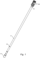
- FIG 1 a perspective view of a drill arrangement for percussion drilling is illustrated.
- the drill arrangement comprises a drill string rod 10 and a drill bit 100.
- the drill string rod 10 comprises an elongated intermediate section 11 extending along a longitudinal axis A (as seen in figure 2 , 4 and 5 ).
- a male coupling 12 is arranged in one end of the intermediate section 11 and a female coupling 13 in the opposite end.
- the male and female couplings are intended to make it possible to connect the drill bit 100 in the forward end of the drill string rod 10, and the female coupling in the rear end of the drill string rod is intended for connecting further drill string rods to form a drill string with the desired length by connecting the male coupling of an identical drill string rod to the female coupling of the adjacent drill string rod.
- further drill string rods 10 are connected to extend the length of drill string 100 as the depth of the bore hole increases.
- male / female couplings are illustrated but other coupling arrangements could be used to adapt the arrangement for different needs.
- the rear end of the drill string 10 is connected to a hydraulically driven piston, not illustrated, arranged to provide the desired axial force and rotation of the drill string, the guide adapter and the drill bit to conduct the percussion drilling.
- the design of the drill string rod, the guide adapter and the drill bit are adapted to specific needs depending on the different types of rock materials and the desired bore hole diameter to be drilled. Larger bore hole diameters require larger dimensions of the different components to ensure that they are able to withstand the loads during drilling.
- the drill string rod could be embodied in different ways and for example the intermediate section 10 could have a circular, rectangular, pentagonal or hexagonal cross-sectional shape as long as the required strength is ensured.
- the intermediate section comprises a passage extending in the center of the intermediate section through the drill string rod to direct flushing media through the drill string to the drill bit arranged in the forward end of the drill string to remove particles and gravel from the bore hole during drilling.
- the flushing media is for example air, water or a mixture of air and water.
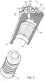
- FIG. 2 and 3 illustrates a perspective view and a side view of the drill bit 100 according to the invention.
- the drill bit comprises a drill bit body 101 intended to extend along axis A.
- the drill bit body has a substantially cylindrical shape with a circular cross-section transverse to axis A.
- a forward body section 103 with a slightly larger radius is arranged to support a front surface 105, and in the rear end 106 the drill bit body is ended by a substantially flat rear surface 107.
- a female coupling 108 is arranged in the rear surface 107 extending coaxially to axis A in the drill bit body 101.
- the female coupling 108 is not visible in figure 2 or 3 but illustrated in figure 5 .
- the angle ⁇ is within the range of 5 to 15° and could be a specific angle there between such as 6, 8, 10, 12 or 14°. And the angle ⁇ is within the range of 30 to 45° and could be a specific angle there between such as 32, 34, 36, 38, 40, 42 or 44°.
- the first radius R1 is within the range of 25 to 65 % of the third radius R3 and could be a specific amount there between such as 28, 32, 36, 40, 44, 48, 52, 56, 60 or 63%.
- said second radius R2 is within the range of 60 to 80 % of the third radius R3 and could be a specific amount there between such as 62, 64, 66, 68, 70, 72, 74, 76 or 78%. This to make it possible to secure a number of buttons in the second and third area in a reliable way.
- the drill bit 100 according to the invention could be embodied in different sizes but the third radius R3 defines the maximum radius of the drill bit body and is within the range of 30 to 65 mm and could be a specific range there between such as 32, 36, 40, 44, 48, 52, 56, 60 or 63 mm.
- buttons 200 are arranged in the drill bit front surface 105.
- the buttons 200 are intended to form the bore hole in the rock and are made of a material that is resistant to wear to ensure the desired drilling action for a long period of time.
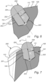
- buttons 200 could be embodied in different ways and examples of buttons are illustrated in different views in figure 2 to 7 .
- All embodiments comprise a button body 201 intended to extend along an axis B.
- the button body 201 (as referred to in figure 6 and 7 ) has a circular cross-sectional shape transverse to axis B with substantially constant radius Rb along the button body, i.e. the cylindrical section 202.
- the button body 201 has a rear end surface 203 and a forward end surface 204.
- the rear end surface 203 is either substantially flat, or convex as the button illustrated in figure 5 to 7
- the forward end surface 204 has a half-spherical, or convex, shape.
- the half-spherical or convex shape ensures that the forward end surface 204 extends from the front surface 105 of the drill bit body 101 such that the front end surface 204 will be in contact with the bottom of the bore hole instead of the front surface 105 of the drill bit body.
- the inner ends of the recesses corresponds to the rear end surface 203 of the buttons arranged in the recesses.
- buttons 200 arranged in the third area surface 112 have a front end surface shape and dimension selected such that the front end surface of the button has at least the same radial extension as the third radius R3, and preferably exceeds the radial extension of the third radius R3 to ensure that the button 200 will form the bore hole and the periphery of the drill bit body 101 is prevented from contact with the side walls of the bore hole.
- the length L of the button body is measured along axis B and depends on the size of the drill bit the button is intended to be used in combination with.
- the length of the button body is measured from the rear end surface 203 to a plane transverse to axis B arranged in the opposite end of the cylindrical section of the button body and is intended to be arranged substantially in line with the first, second or third area of the front surface of the drill bit.
- the lengths L2 and L3 for the buttons arranged in the second 111 and third area surfaces 112 respectively illustrate this length in figures 6 and 7 .
- the cylindrical section of the buttons is fitted in corresponding recesses 120 in the front surface 105 of the drill bit 100.
- the recesses 120 extend in a substantially transverse direction from their respective position in the front surface 105 of the drill bit, i.e. in transverse direction from the first 110, second 111 or third 112 area surfaces into the drill bit body.
- the recesses 120 have a radius corresponding to the button body radius and a depth corresponding to the length L of the button body such that the circular section of the button bodies is fitted within the drill bit body and are reliably secured in the drill bit body.
- the center of the recesses 120 is preferably arranged close to the center of the third or second area surfaces, i.e. the recesses 120 and buttons 220 in respective area surfaces are arranged at substantially the same distance from axis A, such that enough of the drill bit body material remains around the recess to ensure sufficient strength for the button to be secured in the drill bit body.
- buttons 200 and consequently also the recesses 120 formed in the drill bit body, are arranged at a substantially constant distance from each other around the third 112 and second 111 area surfaces to ensure the same strength and characteristics of all button fittings.
- the circular recesses in the second area surface are arranged substantially in the center between the circular recesses in the third area surface 112 to ensure that the maximum distance between adjacent recesses is achieved.
- the distance between the inner end of adjacent circular recesses is at least 2.5 mm.
- buttons 200 arranged in the third area surface 112 have a larger button body radius Rb3 than the button body radius Rb2 of the buttons arranged in the second area to increase the life time of the buttons in the third area that are rotating at higher speed during drilling.
- the buttons in the third area have a button body radius Rb3 within the range of 5 to 9 mm, and preferably within the range of 6 to 8 mm, and could also be 7 mm.
- the number n of buttons in the front surface of the drill bit depends on the size of the drill bit.
- the number of buttons arranged in the third area n3 is 9, 10 or 11.
- the number of buttons arranged in the second area n2 is within the interval of 5 to 10 and preferably 6, 7 8 or 9.
- the drill bits illustrated in the figures furthermore comprises some buttons 200 arranged in the first area surface.
- the buttons in the first area surface 110 preferably have the same dimensions as the buttons arranged in the second area surface 111 since they will move at a lower speed during drilling as a consequence of their positions close to axis A.
- the buttons arranged in the first area surface 110 have the same design as the buttons in the second area surface 111 and the third area surface 112 and are fitted in corresponding recesses in the first area extending substantially perpendicularly from the first area into the drill bit body.
- the number of buttons in the first area is adapted to the size of the drill bit but is preferably within the range of number of 2 to 5.
- the buttons in the first area surface are positioned at selected positions in the first area such that the entire area of the bore hole arranged in front of the first area will be covered when the drill bit rotates. This means that the buttons could be arranged asymmetrically on the first area.
- the drill bit furthermore comprises at least two flushing media outlets 130 arranged in the front surface 105.
- the flushing media is provided via the drill string 10 to the drill bit 100 in order to flush residues and gravel from the bore hole and maintain the desired drilling performance during drilling.
- the illustrated flushing media outlets 130 are arranged in the first area 110 and / or second area surface 111, and a recess 132 extending in substantially radial direction outwards from axis A from the respective outlet 130 is formed in the front surface 105 to direct the flushing media and the flushed material away from the drill bit front surface 105.
- the drill bit body 101 furthermore comprises a peripheral side surface 115 extending from the periphery of the third area surface 112 of the front surface 105 and a number of grooves 134 are formed in the peripheral side surface 115 and the front surface 105.
- the grooves 134 are arranged between adjacent buttons 200 in the third area surface 112 and extend from the third area substantially parallel to axis A towards the rear end of the drill bit to facilitate the transport of flushing material together with residues and particles from the drilling area of the bore hole.
Landscapes
- Engineering & Computer Science (AREA)
- Geology (AREA)
- Life Sciences & Earth Sciences (AREA)
- Mining & Mineral Resources (AREA)
- Physics & Mathematics (AREA)
- Environmental & Geological Engineering (AREA)
- Fluid Mechanics (AREA)
- Mechanical Engineering (AREA)
- General Life Sciences & Earth Sciences (AREA)
- Geochemistry & Mineralogy (AREA)
- Chemical & Material Sciences (AREA)
- Crystallography & Structural Chemistry (AREA)
- Earth Drilling (AREA)
- Processing Of Stones Or Stones Resemblance Materials (AREA)
Claims (13)
- Bohrmeißel (100) zum Schlagbohren, wobei der Bohrmeißel Folgendes umfasst: ein en Bohrmeißelkörper (101), der dazu bestimmt ist, sich entlang einer Achse A zu erstrecken und umfassend eine vordere Oberfläche (105), wobei die vordere Oberfläche eine erste kreisförmige Bereichsoberfläche (110) umfasst, die quer und koaxial zu der Achse A angeordnet ist, eine zweite Bereichsoberfläche (111), die den ersten Bereich (110) umgibt, wobei sich die zweite Bereichsoberfläche (111) in einem Winkel α in Bezug auf eine Ebene erstreckt, die quer zu der Achse A ist, und eine dritte Bereichsoberfläche (112), welche die zweite Bereichsoberfläche (111) umgibt, wobei sich die dritte Bereichsoberfläche (112) derart in einem Winkel β in Bezug auf eine Ebene erstreckt, die quer zu der Achse A ist, dass die vordere Oberfläche (105) eine im Wesentlichen konvexe Form aufweist; und
eine Anzahl (n) von Knöpfen (200), die in der zweiten Oberfläche (111) und der dritten Bereichsoberfläche (112) angeordnet sind, wobei die Knöpfe (200) einen Knopfkörper (201), der sich entlang einer Achse B erstreckt, und eine Länge L entlang der Achse B aufweisen, wobei der Knopfkörper (201) eine kreisförmige Querschnittsform quer zu der Achse B, eine hintere Endoberfläche (203) und eine vordere Endoberfläche (204) aufweist, wobei der Winkel α im Bereich von 5 bis 15 ° liegt, der Winkel β im Bereich von 30 bis 45 ° liegt und die Knöpfe (200) in kreisförmigen Vertiefungen (120) angeordnet sind, die sich im Wesentlichen quer von der zweiten Bereichsoberfläche (111) und der dritten Bereichsoberfläche (112) in den Bohrmeißelkörper (101) erstrecken, wobei die Vertiefungen (120) einen Radius, der dem Knopfkörperradius (Rb) entspricht, und eine Tiefe, die der Länge L des Knopfkörpers (201) derart entspricht, dass die Knopfkörper (201) innerhalb des Bohrmeißelkörpers (101) eingepasst sind, aufweisen, wobei die vordere Endoberfläche (204) in der zweiten Bereichsoberfläche (111) und der dritten Bereichsoberfläche (112) freiliegt, wobei die erste kreisförmige Bereichsoberfläche (110) einen ersten Radius (R1) aufweist, sich die zweite Bereichsoberfläche (111) von dem Umfang der ersten Bereichsoberfläche (110) zu einem zweiten Radius (R2) erstreckt und sich die dritte Bereichsoberfläche (112) von dem Umfang der zweiten Bereichsoberfläche (111) zu einem dritten Radius (R3) erstreckt, wobei der erste Radius (R1) im Bereich von 25 bis 65 % des dritten Radius (R3) liegt und der zweite Radius (R2) im Bereich von 60 bis 80 % des dritten Radius (R3) liegt und wobei der dritte Radius (R3) im Bereich von 30 bis 65 mm liegt und wobei die Anzahl von Knöpfen (200), die in dem dritten Bereich (n3) angeordnet sind, im Bereich von 9 bis 11 liegt. - Bohrmeißel (100) nach Anspruch 1, wobei die Knöpfe (200), die in der dritten Bereichsoberfläche (112) angeordnet sind, einen größeren Knopfkörperradius (Rb3) als den Knopfkörperradius (Rb2) der Knöpfe, die in der zweiten Bereichsoberfläche (111) angeordnet sind, aufweisen.
- Bohrmeißel (100) nach einem der vorhergehenden Ansprüche, wobei der Knopfkörper (201) einen zylindrischen Abschnitt (202) umfasst, der dazu bestimmt ist, innerhalb der Vertiefung (120) in dem Bohrmeißelkörper (101) angeordnet zu sein, und die Länge L des Knopfkörpers (201) entlang der Achse B von der Endoberfläche (203) zu einer Ebene quer zu der Achse B, die in dem gegenüberliegenden Ende des zylindrischen Abschnitts (202) des Bohrmeißelkörpers angeordnet ist, gemessen wird.
- Bohrmeißel (100) nach einem der vorhergehenden Ansprüche, wobei die vordere Endoberfläche (204) der Knöpfe (200) eine halbkugelförmige oder konvexe Form derart aufweist, dass sich die vordere Endoberfläche (204) von der zweiten Bereichsoberfläche (111) und der dritten Bereichsoberfläche (112) des Bohrmeißelkörpers (101) erstreckt.
- Bohrmeißel (100) nach einem der vorhergehenden Ansprüche, wobei die Knöpfe (200) in der dritten Bereichsoberfläche (112) einen Knopfkörperradius (Rb3) im Bereich von 5 bis 9 mm und bevorzugt im Bereich von 6 bis 8 mm aufweisen.
- Bohrmeißel (100) nach einem der vorhergehenden Ansprüche, wobei das Verhältnis zwischen dem dritten Radius (R3) und der Anzahl der Knöpfe, die in dem dritten Bereich angeordnet sind, (n3)*(Knopfkörperradius der Knöpfe in dem dritten Bereich (Rb3)), im Bereich von 0,6 und 0,8 liegt, d.h. das Verhältnis = R3/(n3*Rb3) im Bereich von 0,6 bis 0,8 liegt.
- Bohrmeißel (100) nach einem der Ansprüche 1 bis 4, wobei die Anzahl von Knöpfen, die in dem zweiten Bereich (n2) angeordnet sind, innerhalb des Intervalls von 5 bis 10 liegt.
- Bohrmeißel (100) nach einem der Ansprüche 2 bis 7, wobei das Verhältnis zwischen der Knopfkörperlänge (L3) und dem Knopfkörperradius (Rb3) der Knöpfe in dem dritten Bereich, d.h. das Verhältnis = L3/Rb3, und das Verhältnis zwischen der Knopfkörperlänge (L2) und dem Knopfkörperradius (Rb2) der Knöpfe in dem zweiten Bereich, d.h. das Verhältnis = L2/Rb2, beide im Bereich von 1,8 bis 2,2 liegen.
- Bohrmeißel (100) nach einem der Ansprüche 2 bis 8, wobei die kreisförmigen Vertiefungen in dem dritten Bereich und die kreisförmigen Vertiefungen in dem zweiten Bereich derart angeordnet sind, dass der Abstand zwischen dem inneren Ende benachbarter kreisförmiger Vertiefungen mindestens 2,5 mm beträgt.
- Bohrmeißel (100) nach einem der vorhergehenden Ansprüche, wobei mindestens zwei Spülmedienauslässe (130) in der vorderen Oberfläche (105) angeordnet sind und eine Vertiefung (132), die sich in im Wesentlichen radialer Richtung von der Achse A nach außen von dem jeweiligen Auslass (130) erstreckt, in der vorderen Oberfläche (105) gebildet ist.
- Bohrmeißel (100) nach Anspruch 10, wobei die Spülmedienauslässe (130) in dem ersten Bereich (110) und/oder der zweiten Bereichsoberfläche (111) angeordnet sind.
- Bohrmeißel (100) nach einem der vorhergehenden Ansprüche, wobei die Knöpfe (200) in der dritten Bereichsoberfläche (112) in einem im Wesentlichen gleichen Abstand von der Achse A und in einem im Wesentlichen konstanten Abstand voneinander um die dritte Bereichsoberfläche (112) angeordnet sind.
- Bohrmeißel (100) nach einem der vorhergehenden Ansprüche, wobei der Bohrmeißelköper (101) eine Umfangsseitenoberfläche (115), die sich von dem Umfang der vorderen Oberfläche (105) zu einem hinteren Ende des Bohrmeißels (100) erstreckt, umfasst und eine Anzahl von Nuten (134) in der Umfangsseitenoberfläche (115) und der vorderen Oberfläche (105) gebildet sind, wobei die Nuten (134) zwischen benachbarten Knöpfen (200) in der dritten Bereichsoberfläche (112) angeordnet sind und sich von der dritten Bereichsoberfläche (112) im Wesentlichen parallel zu der Achse A zu dem hinteren Ende des Bohrmeißels erstrecken.
Priority Applications (14)
| Application Number | Priority Date | Filing Date | Title |
|---|---|---|---|
| PL19184793.8T PL3760828T5 (pl) | 2019-07-05 | 2019-07-05 | Narzędzie wiertnicze |
| EP19184793.8A EP3760828B2 (de) | 2019-07-05 | 2019-07-05 | Bohrmeissel |
| FIEP19184793.8T FI3760828T4 (fi) | 2019-07-05 | 2019-07-05 | Poranterä |
| US17/624,825 US12000213B2 (en) | 2019-07-05 | 2020-07-03 | Drill bit |
| CN202080039524.5A CN113891978A (zh) | 2019-07-05 | 2020-07-03 | 一种钻头 |
| BR112021026631A BR112021026631A2 (pt) | 2019-07-05 | 2020-07-03 | Broca |
| PE2021001876A PE20220112A1 (es) | 2019-07-05 | 2020-07-03 | Barrena de perforacion |
| CA3136774A CA3136774A1 (en) | 2019-07-05 | 2020-07-03 | Drill bit |
| JP2022500013A JP2022540990A (ja) | 2019-07-05 | 2020-07-03 | ドリルビット |
| PCT/EP2020/068753 WO2021004909A1 (en) | 2019-07-05 | 2020-07-03 | Drill bit |
| AU2020310491A AU2020310491B2 (en) | 2019-07-05 | 2020-07-03 | Drill bit |
| KR1020217042336A KR20220027078A (ko) | 2019-07-05 | 2020-07-03 | 드릴 비트 |
| MX2022000014A MX2022000014A (es) | 2019-07-05 | 2020-07-03 | Barrena de perforacion. |
| CL2022000004A CL2022000004A1 (es) | 2019-07-05 | 2022-01-03 | Barrena de perforación. |
Applications Claiming Priority (1)
| Application Number | Priority Date | Filing Date | Title |
|---|---|---|---|
| EP19184793.8A EP3760828B2 (de) | 2019-07-05 | 2019-07-05 | Bohrmeissel |
Publications (3)
| Publication Number | Publication Date |
|---|---|
| EP3760828A1 EP3760828A1 (de) | 2021-01-06 |
| EP3760828B1 EP3760828B1 (de) | 2022-04-20 |
| EP3760828B2 true EP3760828B2 (de) | 2025-05-07 |
Family
ID=67184934
Family Applications (1)
| Application Number | Title | Priority Date | Filing Date |
|---|---|---|---|
| EP19184793.8A Active EP3760828B2 (de) | 2019-07-05 | 2019-07-05 | Bohrmeissel |
Country Status (14)
| Country | Link |
|---|---|
| US (1) | US12000213B2 (de) |
| EP (1) | EP3760828B2 (de) |
| JP (1) | JP2022540990A (de) |
| KR (1) | KR20220027078A (de) |
| CN (1) | CN113891978A (de) |
| AU (1) | AU2020310491B2 (de) |
| BR (1) | BR112021026631A2 (de) |
| CA (1) | CA3136774A1 (de) |
| CL (1) | CL2022000004A1 (de) |
| FI (1) | FI3760828T4 (de) |
| MX (1) | MX2022000014A (de) |
| PE (1) | PE20220112A1 (de) |
| PL (1) | PL3760828T5 (de) |
| WO (1) | WO2021004909A1 (de) |
Families Citing this family (3)
| Publication number | Priority date | Publication date | Assignee | Title |
|---|---|---|---|---|
| EP4116020A1 (de) * | 2021-07-06 | 2023-01-11 | Seco Tools Ab | Verarbeitungswerkzeug und verarbeitungswerkzeuganordnung |
| WO2023280505A1 (en) * | 2021-07-06 | 2023-01-12 | Seco Tools Ab | A processing tool and a processing tool assembly |
| US20240307980A1 (en) * | 2021-07-06 | 2024-09-19 | Seco Tools Ab | Processing tool and a processing tool assembly |
Citations (3)
| Publication number | Priority date | Publication date | Assignee | Title |
|---|---|---|---|---|
| EP0345096A1 (de) † | 1988-06-03 | 1989-12-06 | Boart International Limited | Bohrmeissel |
| WO2013150078A2 (en) † | 2012-04-05 | 2013-10-10 | Mincon International | Symmetrical bit for directional drilling tool |
| US20140182939A1 (en) † | 2012-12-28 | 2014-07-03 | Smith International, Inc. | Percussion drill bit with conical cutting elements |
Family Cites Families (13)
| Publication number | Priority date | Publication date | Assignee | Title |
|---|---|---|---|---|
| JPS57156590U (de) * | 1981-03-25 | 1982-10-01 | ||
| CN1011322B (zh) * | 1987-01-20 | 1991-01-23 | 英格索尔-兰德公司 | 耐磨凿岩钻头 |
| SU1581837A1 (ru) | 1987-11-17 | 1990-07-30 | Кыштымский машиностроительный завод им.М.И.Калинина | Долото дл ударно-вращательного бурени |
| SE521935C2 (sv) | 2000-06-30 | 2003-12-23 | Sandvik Ab | Bergborrkrona för slående bergborrning |
| AR044551A1 (es) | 2003-05-26 | 2005-09-21 | Shell Int Research | Cabeza perforadora con percusion sistema de perforacion que comprende dicha cabeza perforadora y un metodo para perforar un pozo |
| SE526344C2 (sv) * | 2003-12-09 | 2005-08-30 | Sandvik Intellectual Property | Bergborrkrona |
| JP4706639B2 (ja) * | 2007-01-18 | 2011-06-22 | 三菱マテリアル株式会社 | 掘削工具 |
| IES20090701A2 (en) | 2009-08-31 | 2010-05-12 | Minroc Techn Promotions Ltd | A drill bit assembly for fluid-operated percussion drill tools |
| EP2586960B1 (de) * | 2011-10-27 | 2016-01-13 | Sandvik Intellectual Property AB | Bohrspitze mit einem absenkknopf und gesteinsbohrwerkzeug zur verwendung mit einer solchen bohrspitze |
| EP2592216B1 (de) * | 2011-11-11 | 2018-11-07 | Sandvik Intellectual Property AB | Bohrkrone für ein Steinbohrwerkzeug und Steinbohrwerkzeug |
| EP2921639A1 (de) * | 2014-03-18 | 2015-09-23 | Sandvik Intellectual Property AB | Schlagbohrer mit mehreren Sätzen von Schneideinsätzen |
| CN204343987U (zh) * | 2014-12-05 | 2015-05-20 | 江西耀升钨业股份有限公司 | 一种钻头及其适配该钻头的球齿 |
| CN207315236U (zh) * | 2017-10-13 | 2018-05-04 | 浙江普兰卡钎具有限公司 | 高风压潜孔钻头 |
-
2019
- 2019-07-05 EP EP19184793.8A patent/EP3760828B2/de active Active
- 2019-07-05 PL PL19184793.8T patent/PL3760828T5/pl unknown
- 2019-07-05 FI FIEP19184793.8T patent/FI3760828T4/fi active
-
2020
- 2020-07-03 PE PE2021001876A patent/PE20220112A1/es unknown
- 2020-07-03 BR BR112021026631A patent/BR112021026631A2/pt active Search and Examination
- 2020-07-03 CN CN202080039524.5A patent/CN113891978A/zh active Pending
- 2020-07-03 CA CA3136774A patent/CA3136774A1/en active Pending
- 2020-07-03 MX MX2022000014A patent/MX2022000014A/es unknown
- 2020-07-03 KR KR1020217042336A patent/KR20220027078A/ko not_active Ceased
- 2020-07-03 JP JP2022500013A patent/JP2022540990A/ja active Pending
- 2020-07-03 AU AU2020310491A patent/AU2020310491B2/en active Active
- 2020-07-03 WO PCT/EP2020/068753 patent/WO2021004909A1/en not_active Ceased
- 2020-07-03 US US17/624,825 patent/US12000213B2/en active Active
-
2022
- 2022-01-03 CL CL2022000004A patent/CL2022000004A1/es unknown
Patent Citations (3)
| Publication number | Priority date | Publication date | Assignee | Title |
|---|---|---|---|---|
| EP0345096A1 (de) † | 1988-06-03 | 1989-12-06 | Boart International Limited | Bohrmeissel |
| WO2013150078A2 (en) † | 2012-04-05 | 2013-10-10 | Mincon International | Symmetrical bit for directional drilling tool |
| US20140182939A1 (en) † | 2012-12-28 | 2014-07-03 | Smith International, Inc. | Percussion drill bit with conical cutting elements |
Also Published As
| Publication number | Publication date |
|---|---|
| PE20220112A1 (es) | 2022-01-26 |
| US12000213B2 (en) | 2024-06-04 |
| EP3760828A1 (de) | 2021-01-06 |
| US20220268104A1 (en) | 2022-08-25 |
| PL3760828T3 (pl) | 2022-06-20 |
| CA3136774A1 (en) | 2021-01-14 |
| JP2022540990A (ja) | 2022-09-21 |
| AU2020310491B2 (en) | 2025-07-17 |
| CN113891978A (zh) | 2022-01-04 |
| FI3760828T4 (fi) | 2025-06-30 |
| MX2022000014A (es) | 2022-06-08 |
| WO2021004909A1 (en) | 2021-01-14 |
| PL3760828T5 (pl) | 2025-07-07 |
| CL2022000004A1 (es) | 2022-08-19 |
| EP3760828B1 (de) | 2022-04-20 |
| BR112021026631A2 (pt) | 2022-02-15 |
| KR20220027078A (ko) | 2022-03-07 |
| AU2020310491A1 (en) | 2021-12-23 |
Similar Documents
| Publication | Publication Date | Title |
|---|---|---|
| US7641002B2 (en) | Drill bit | |
| EP3760828B1 (de) | Bohrmeissel | |
| US4473125A (en) | Insert for drill bits and drill stabilizers | |
| CA2852150C (en) | Drill bit having a sunken button and rock drilling tool for use with such a drill bit | |
| KR20070045257A (ko) | 착암 드릴 비트 및 나사 조인트 | |
| US20220228445A1 (en) | Auger bit | |
| US11808086B2 (en) | Drill string rod | |
| OA20449A (en) | Drill bit | |
| CN210317170U (zh) | 一种高性能潜孔钻头 | |
| EP3741956A1 (de) | Bohrstrangstange | |
| EP3690181A1 (de) | Führungsadapter mit verschleisseinsätzen | |
| SE530651C2 (sv) | Borrkrona för enstegsankarbultning och en enstegsborrande apparatur | |
| EP3751092B1 (de) | Führungsadapter | |
| EP3690180A1 (de) | Schlagbohrer mit verschleisseinsätzen | |
| US12312866B2 (en) | Drill assembly for percussive drilling, a drill bit and a drill string element | |
| CN210033296U (zh) | 一种外螺纹球齿钎头 | |
| RU2115796C1 (ru) | Гидродинамический расширитель-стабилизатор | |
| SE530905C2 (sv) | Bergborrkrona för enstegsankarbultning och enstegsborrande apparatur | |
| SE530904C2 (sv) | Bergborrkrona för enstegsankarbultning och enstegsborrande apparatur |
Legal Events
| Date | Code | Title | Description |
|---|---|---|---|
| PUAI | Public reference made under article 153(3) epc to a published international application that has entered the european phase |
Free format text: ORIGINAL CODE: 0009012 |
|
| STAA | Information on the status of an ep patent application or granted ep patent |
Free format text: STATUS: THE APPLICATION HAS BEEN PUBLISHED |
|
| AK | Designated contracting states |
Kind code of ref document: A1 Designated state(s): AL AT BE BG CH CY CZ DE DK EE ES FI FR GB GR HR HU IE IS IT LI LT LU LV MC MK MT NL NO PL PT RO RS SE SI SK SM TR |
|
| AX | Request for extension of the european patent |
Extension state: BA ME |
|
| STAA | Information on the status of an ep patent application or granted ep patent |
Free format text: STATUS: REQUEST FOR EXAMINATION WAS MADE |
|
| 17P | Request for examination filed |
Effective date: 20210706 |
|
| RBV | Designated contracting states (corrected) |
Designated state(s): AL AT BE BG CH CY CZ DE DK EE ES FI FR GB GR HR HU IE IS IT LI LT LU LV MC MK MT NL NO PL PT RO RS SE SI SK SM TR |
|
| TPAC | Observations filed by third parties |
Free format text: ORIGINAL CODE: EPIDOSNTIPA |
|
| GRAP | Despatch of communication of intention to grant a patent |
Free format text: ORIGINAL CODE: EPIDOSNIGR1 |
|
| STAA | Information on the status of an ep patent application or granted ep patent |
Free format text: STATUS: GRANT OF PATENT IS INTENDED |
|
| INTG | Intention to grant announced |
Effective date: 20211123 |
|
| GRAS | Grant fee paid |
Free format text: ORIGINAL CODE: EPIDOSNIGR3 |
|
| GRAA | (expected) grant |
Free format text: ORIGINAL CODE: 0009210 |
|
| STAA | Information on the status of an ep patent application or granted ep patent |
Free format text: STATUS: THE PATENT HAS BEEN GRANTED |
|
| AK | Designated contracting states |
Kind code of ref document: B1 Designated state(s): AL AT BE BG CH CY CZ DE DK EE ES FI FR GB GR HR HU IE IS IT LI LT LU LV MC MK MT NL NO PL PT RO RS SE SI SK SM TR |
|
| REG | Reference to a national code |
Ref country code: GB Ref legal event code: FG4D |
|
| REG | Reference to a national code |
Ref country code: CH Ref legal event code: EP |
|
| REG | Reference to a national code |
Ref country code: IE Ref legal event code: FG4D |
|
| REG | Reference to a national code |
Ref country code: DE Ref legal event code: R096 Ref document number: 602019013821 Country of ref document: DE |
|
| REG | Reference to a national code |
Ref country code: AT Ref legal event code: REF Ref document number: 1485277 Country of ref document: AT Kind code of ref document: T Effective date: 20220515 |
|
| REG | Reference to a national code |
Ref country code: FI Ref legal event code: FGE |
|
| REG | Reference to a national code |
Ref country code: NO Ref legal event code: T2 Effective date: 20220420 |
|
| REG | Reference to a national code |
Ref country code: LT Ref legal event code: MG9D |
|
| REG | Reference to a national code |
Ref country code: NL Ref legal event code: MP Effective date: 20220420 |
|
| PG25 | Lapsed in a contracting state [announced via postgrant information from national office to epo] |
Ref country code: NL Free format text: LAPSE BECAUSE OF FAILURE TO SUBMIT A TRANSLATION OF THE DESCRIPTION OR TO PAY THE FEE WITHIN THE PRESCRIBED TIME-LIMIT Effective date: 20220420 |
|
| PG25 | Lapsed in a contracting state [announced via postgrant information from national office to epo] |
Ref country code: SE Free format text: LAPSE BECAUSE OF FAILURE TO SUBMIT A TRANSLATION OF THE DESCRIPTION OR TO PAY THE FEE WITHIN THE PRESCRIBED TIME-LIMIT Effective date: 20220420 Ref country code: PT Free format text: LAPSE BECAUSE OF FAILURE TO SUBMIT A TRANSLATION OF THE DESCRIPTION OR TO PAY THE FEE WITHIN THE PRESCRIBED TIME-LIMIT Effective date: 20220822 Ref country code: LT Free format text: LAPSE BECAUSE OF FAILURE TO SUBMIT A TRANSLATION OF THE DESCRIPTION OR TO PAY THE FEE WITHIN THE PRESCRIBED TIME-LIMIT Effective date: 20220420 Ref country code: HR Free format text: LAPSE BECAUSE OF FAILURE TO SUBMIT A TRANSLATION OF THE DESCRIPTION OR TO PAY THE FEE WITHIN THE PRESCRIBED TIME-LIMIT Effective date: 20220420 Ref country code: GR Free format text: LAPSE BECAUSE OF FAILURE TO SUBMIT A TRANSLATION OF THE DESCRIPTION OR TO PAY THE FEE WITHIN THE PRESCRIBED TIME-LIMIT Effective date: 20220721 Ref country code: ES Free format text: LAPSE BECAUSE OF FAILURE TO SUBMIT A TRANSLATION OF THE DESCRIPTION OR TO PAY THE FEE WITHIN THE PRESCRIBED TIME-LIMIT Effective date: 20220420 Ref country code: BG Free format text: LAPSE BECAUSE OF FAILURE TO SUBMIT A TRANSLATION OF THE DESCRIPTION OR TO PAY THE FEE WITHIN THE PRESCRIBED TIME-LIMIT Effective date: 20220720 |
|
| PG25 | Lapsed in a contracting state [announced via postgrant information from national office to epo] |
Ref country code: RS Free format text: LAPSE BECAUSE OF FAILURE TO SUBMIT A TRANSLATION OF THE DESCRIPTION OR TO PAY THE FEE WITHIN THE PRESCRIBED TIME-LIMIT Effective date: 20220420 Ref country code: LV Free format text: LAPSE BECAUSE OF FAILURE TO SUBMIT A TRANSLATION OF THE DESCRIPTION OR TO PAY THE FEE WITHIN THE PRESCRIBED TIME-LIMIT Effective date: 20220420 Ref country code: IS Free format text: LAPSE BECAUSE OF FAILURE TO SUBMIT A TRANSLATION OF THE DESCRIPTION OR TO PAY THE FEE WITHIN THE PRESCRIBED TIME-LIMIT Effective date: 20220820 |
|
| REG | Reference to a national code |
Ref country code: DE Ref legal event code: R026 Ref document number: 602019013821 Country of ref document: DE |
|
| PLBI | Opposition filed |
Free format text: ORIGINAL CODE: 0009260 |
|
| PG25 | Lapsed in a contracting state [announced via postgrant information from national office to epo] |
Ref country code: SM Free format text: LAPSE BECAUSE OF FAILURE TO SUBMIT A TRANSLATION OF THE DESCRIPTION OR TO PAY THE FEE WITHIN THE PRESCRIBED TIME-LIMIT Effective date: 20220420 Ref country code: SK Free format text: LAPSE BECAUSE OF FAILURE TO SUBMIT A TRANSLATION OF THE DESCRIPTION OR TO PAY THE FEE WITHIN THE PRESCRIBED TIME-LIMIT Effective date: 20220420 Ref country code: RO Free format text: LAPSE BECAUSE OF FAILURE TO SUBMIT A TRANSLATION OF THE DESCRIPTION OR TO PAY THE FEE WITHIN THE PRESCRIBED TIME-LIMIT Effective date: 20220420 Ref country code: EE Free format text: LAPSE BECAUSE OF FAILURE TO SUBMIT A TRANSLATION OF THE DESCRIPTION OR TO PAY THE FEE WITHIN THE PRESCRIBED TIME-LIMIT Effective date: 20220420 Ref country code: DK Free format text: LAPSE BECAUSE OF FAILURE TO SUBMIT A TRANSLATION OF THE DESCRIPTION OR TO PAY THE FEE WITHIN THE PRESCRIBED TIME-LIMIT Effective date: 20220420 Ref country code: CZ Free format text: LAPSE BECAUSE OF FAILURE TO SUBMIT A TRANSLATION OF THE DESCRIPTION OR TO PAY THE FEE WITHIN THE PRESCRIBED TIME-LIMIT Effective date: 20220420 |
|
| REG | Reference to a national code |
Ref country code: DE Ref legal event code: R119 Ref document number: 602019013821 Country of ref document: DE |
|
| PG25 | Lapsed in a contracting state [announced via postgrant information from national office to epo] |
Ref country code: MC Free format text: LAPSE BECAUSE OF FAILURE TO SUBMIT A TRANSLATION OF THE DESCRIPTION OR TO PAY THE FEE WITHIN THE PRESCRIBED TIME-LIMIT Effective date: 20220420 |
|
| REG | Reference to a national code |
Ref country code: CH Ref legal event code: PL |
|
| 26 | Opposition filed |
Opponent name: ROBIT PLC Effective date: 20230120 |
|
| REG | Reference to a national code |
Ref country code: BE Ref legal event code: MM Effective date: 20220731 |
|
| PG25 | Lapsed in a contracting state [announced via postgrant information from national office to epo] |
Ref country code: AL Free format text: LAPSE BECAUSE OF FAILURE TO SUBMIT A TRANSLATION OF THE DESCRIPTION OR TO PAY THE FEE WITHIN THE PRESCRIBED TIME-LIMIT Effective date: 20220420 |
|
| PLAX | Notice of opposition and request to file observation + time limit sent |
Free format text: ORIGINAL CODE: EPIDOSNOBS2 |
|
| PG25 | Lapsed in a contracting state [announced via postgrant information from national office to epo] |
Ref country code: LU Free format text: LAPSE BECAUSE OF NON-PAYMENT OF DUE FEES Effective date: 20220705 Ref country code: LI Free format text: LAPSE BECAUSE OF NON-PAYMENT OF DUE FEES Effective date: 20220731 Ref country code: FR Free format text: LAPSE BECAUSE OF NON-PAYMENT OF DUE FEES Effective date: 20220731 Ref country code: CH Free format text: LAPSE BECAUSE OF NON-PAYMENT OF DUE FEES Effective date: 20220731 |
|
| PG25 | Lapsed in a contracting state [announced via postgrant information from national office to epo] |
Ref country code: SI Free format text: LAPSE BECAUSE OF FAILURE TO SUBMIT A TRANSLATION OF THE DESCRIPTION OR TO PAY THE FEE WITHIN THE PRESCRIBED TIME-LIMIT Effective date: 20220420 Ref country code: DE Free format text: LAPSE BECAUSE OF NON-PAYMENT OF DUE FEES Effective date: 20230201 Ref country code: BE Free format text: LAPSE BECAUSE OF NON-PAYMENT OF DUE FEES Effective date: 20220731 |
|
| PLBB | Reply of patent proprietor to notice(s) of opposition received |
Free format text: ORIGINAL CODE: EPIDOSNOBS3 |
|
| PG25 | Lapsed in a contracting state [announced via postgrant information from national office to epo] |
Ref country code: IE Free format text: LAPSE BECAUSE OF NON-PAYMENT OF DUE FEES Effective date: 20220705 |
|
| REG | Reference to a national code |
Ref country code: AT Ref legal event code: UEP Ref document number: 1485277 Country of ref document: AT Kind code of ref document: T Effective date: 20220420 |
|
| PG25 | Lapsed in a contracting state [announced via postgrant information from national office to epo] |
Ref country code: IT Free format text: LAPSE BECAUSE OF FAILURE TO SUBMIT A TRANSLATION OF THE DESCRIPTION OR TO PAY THE FEE WITHIN THE PRESCRIBED TIME-LIMIT Effective date: 20220420 |
|
| PG25 | Lapsed in a contracting state [announced via postgrant information from national office to epo] |
Ref country code: MK Free format text: LAPSE BECAUSE OF FAILURE TO SUBMIT A TRANSLATION OF THE DESCRIPTION OR TO PAY THE FEE WITHIN THE PRESCRIBED TIME-LIMIT Effective date: 20220420 Ref country code: CY Free format text: LAPSE BECAUSE OF FAILURE TO SUBMIT A TRANSLATION OF THE DESCRIPTION OR TO PAY THE FEE WITHIN THE PRESCRIBED TIME-LIMIT Effective date: 20220420 |
|
| PG25 | Lapsed in a contracting state [announced via postgrant information from national office to epo] |
Ref country code: HU Free format text: LAPSE BECAUSE OF FAILURE TO SUBMIT A TRANSLATION OF THE DESCRIPTION OR TO PAY THE FEE WITHIN THE PRESCRIBED TIME-LIMIT; INVALID AB INITIO Effective date: 20190705 |
|
| PG25 | Lapsed in a contracting state [announced via postgrant information from national office to epo] |
Ref country code: MT Free format text: LAPSE BECAUSE OF FAILURE TO SUBMIT A TRANSLATION OF THE DESCRIPTION OR TO PAY THE FEE WITHIN THE PRESCRIBED TIME-LIMIT Effective date: 20220420 |
|
| PG25 | Lapsed in a contracting state [announced via postgrant information from national office to epo] |
Ref country code: BG Free format text: LAPSE BECAUSE OF FAILURE TO SUBMIT A TRANSLATION OF THE DESCRIPTION OR TO PAY THE FEE WITHIN THE PRESCRIBED TIME-LIMIT Effective date: 20220420 |
|
| PG25 | Lapsed in a contracting state [announced via postgrant information from national office to epo] |
Ref country code: BG Free format text: LAPSE BECAUSE OF FAILURE TO SUBMIT A TRANSLATION OF THE DESCRIPTION OR TO PAY THE FEE WITHIN THE PRESCRIBED TIME-LIMIT Effective date: 20220420 |
|
| PUAH | Patent maintained in amended form |
Free format text: ORIGINAL CODE: 0009272 |
|
| STAA | Information on the status of an ep patent application or granted ep patent |
Free format text: STATUS: PATENT MAINTAINED AS AMENDED |
|
| 27A | Patent maintained in amended form |
Effective date: 20250507 |
|
| AK | Designated contracting states |
Kind code of ref document: B2 Designated state(s): AL AT BE BG CH CY CZ DE DK EE ES FI FR GB GR HR HU IE IS IT LI LT LU LV MC MK MT NL NO PL PT RO RS SE SI SK SM TR |
|
| REG | Reference to a national code |
Ref country code: DE Ref legal event code: R102 Ref document number: 602019013821 Country of ref document: DE |
|
| PGFP | Annual fee paid to national office [announced via postgrant information from national office to epo] |
Ref country code: PL Payment date: 20250612 Year of fee payment: 7 |
|
| PGFP | Annual fee paid to national office [announced via postgrant information from national office to epo] |
Ref country code: GB Payment date: 20250529 Year of fee payment: 7 |
|
| PGFP | Annual fee paid to national office [announced via postgrant information from national office to epo] |
Ref country code: FI Payment date: 20250715 Year of fee payment: 7 |
|
| PGFP | Annual fee paid to national office [announced via postgrant information from national office to epo] |
Ref country code: NO Payment date: 20250709 Year of fee payment: 7 |
|
| PGFP | Annual fee paid to national office [announced via postgrant information from national office to epo] |
Ref country code: AT Payment date: 20250625 Year of fee payment: 7 |