EP3760826A2 - A screening device, a roof window comprising such a screening device and a method for mounting such a screening device on a roof window - Google Patents
A screening device, a roof window comprising such a screening device and a method for mounting such a screening device on a roof window Download PDFInfo
- Publication number
- EP3760826A2 EP3760826A2 EP20180731.0A EP20180731A EP3760826A2 EP 3760826 A2 EP3760826 A2 EP 3760826A2 EP 20180731 A EP20180731 A EP 20180731A EP 3760826 A2 EP3760826 A2 EP 3760826A2
- Authority
- EP
- European Patent Office
- Prior art keywords
- screening device
- roof window
- rod
- receiving element
- adapter
- Prior art date
- Legal status (The legal status is an assumption and is not a legal conclusion. Google has not performed a legal analysis and makes no representation as to the accuracy of the status listed.)
- Pending
Links
- 238000012216 screening Methods 0.000 title claims abstract description 121
- 238000000034 method Methods 0.000 title claims description 10
- 239000000696 magnetic material Substances 0.000 claims description 11
- 238000010276 construction Methods 0.000 description 4
- 239000011521 glass Substances 0.000 description 2
- 238000003780 insertion Methods 0.000 description 2
- 230000037431 insertion Effects 0.000 description 2
- 239000000463 material Substances 0.000 description 2
- 239000004744 fabric Substances 0.000 description 1
- 230000005484 gravity Effects 0.000 description 1
- 238000004519 manufacturing process Methods 0.000 description 1
- 230000013011 mating Effects 0.000 description 1
- 239000002184 metal Substances 0.000 description 1
- 238000012986 modification Methods 0.000 description 1
- 230000004048 modification Effects 0.000 description 1
- 238000004806 packaging method and process Methods 0.000 description 1
Images


Classifications
-
- E—FIXED CONSTRUCTIONS
- E06—DOORS, WINDOWS, SHUTTERS, OR ROLLER BLINDS IN GENERAL; LADDERS
- E06B—FIXED OR MOVABLE CLOSURES FOR OPENINGS IN BUILDINGS, VEHICLES, FENCES OR LIKE ENCLOSURES IN GENERAL, e.g. DOORS, WINDOWS, BLINDS, GATES
- E06B9/00—Screening or protective devices for wall or similar openings, with or without operating or securing mechanisms; Closures of similar construction
- E06B9/56—Operating, guiding or securing devices or arrangements for roll-type closures; Spring drums; Tape drums; Counterweighting arrangements therefor
- E06B9/92—Means allowing the closures to be shifted out of the plane of the opening
-
- E—FIXED CONSTRUCTIONS
- E04—BUILDING
- E04D—ROOF COVERINGS; SKY-LIGHTS; GUTTERS; ROOF-WORKING TOOLS
- E04D13/00—Special arrangements or devices in connection with roof coverings; Protection against birds; Roof drainage ; Sky-lights
- E04D13/03—Sky-lights; Domes; Ventilating sky-lights
- E04D13/033—Sky-lights; Domes; Ventilating sky-lights provided with means for controlling the light-transmission or the heat-reflection, (e.g. shields, reflectors, cleaning devices)
-
- E—FIXED CONSTRUCTIONS
- E06—DOORS, WINDOWS, SHUTTERS, OR ROLLER BLINDS IN GENERAL; LADDERS
- E06B—FIXED OR MOVABLE CLOSURES FOR OPENINGS IN BUILDINGS, VEHICLES, FENCES OR LIKE ENCLOSURES IN GENERAL, e.g. DOORS, WINDOWS, BLINDS, GATES
- E06B9/00—Screening or protective devices for wall or similar openings, with or without operating or securing mechanisms; Closures of similar construction
- E06B9/02—Shutters, movable grilles, or other safety closing devices, e.g. against burglary
- E06B9/08—Roll-type closures
- E06B9/11—Roller shutters
-
- E—FIXED CONSTRUCTIONS
- E06—DOORS, WINDOWS, SHUTTERS, OR ROLLER BLINDS IN GENERAL; LADDERS
- E06B—FIXED OR MOVABLE CLOSURES FOR OPENINGS IN BUILDINGS, VEHICLES, FENCES OR LIKE ENCLOSURES IN GENERAL, e.g. DOORS, WINDOWS, BLINDS, GATES
- E06B9/00—Screening or protective devices for wall or similar openings, with or without operating or securing mechanisms; Closures of similar construction
- E06B9/24—Screens or other constructions affording protection against light, especially against sunshine; Similar screens for privacy or appearance; Slat blinds
- E06B9/40—Roller blinds
- E06B9/42—Parts or details of roller blinds, e.g. suspension devices, blind boxes
Definitions
- the present invention relates to a screening device comprising a top element adapted for being mounted on or adjacent to a top frame member of a roof window, and a connection device adapted for connecting the screening device to the roof window on or adjacent to the top frame member of the roof window in such a manner that the screening device may be displaced to a position in which it forms an angle with the roof window.
- Such a screening device may for instance be a roller shutter or an awning blind.
- Such a screening device constitutes an external screening device to be mounted to the external side of a roof window, which comprises a frame and a sash connected to the frame by means of a set of hinges defining a hinge axis.
- the screening device is provided with side rails and a top casing.
- a bottom bar is positioned at the free end of the screening body.
- the screening body may e.g. be a shutter body/panzer or an awning cloth.
- connecting elements in the form of mounting fittings, or sliding guides are provided and on which the side rails may slide.
- the top casing of the roller shutter is rotatably connected to the top member of the frame, and the side rails are rigidly connected to the top casing.
- the hinge connection between the top casing and the frame comprises receiving means such as a recess on a mounting element connected to the frame to receive a pin on the top casing.
- the screening body is unwound from its non-screening position in the top casing and guided in the side rails to a screening position.
- the unwinding and winding-up is carried out either manually or by electrical operation.
- the sash is pivoted to a number of desired open positions in which the plane of the sash forms an arbitrary angle with the plane of the frame.
- the screening device follows the movement as the mounting fittings slide in the respective side rail.
- Such a screening device is for instance known from the applicant's patent applications DE 202012010009 U and WO 02/06621 A1 .
- connection device comprises at least one rod-shaped element provided on the top element and extending in a longitudinal direction of the top element, a receiving element adapted for being mounted on or adjacent to the top frame member or a side frame member of the roof window, and an adapter element comprising a first part adapted for locking engagement with the receiving element and a second part adapted for connection to the rod-shaped element in such a way that the second part of the adapter element is freely rotatable with respect to the at least one rod-shaped element at least after the first part of the adapter element is brought into engagement with the receiving element.
- a screening device having such a construction that, once connected, the adapter element may only be released from the receiving element by manual disengagement of the first part, and that the adapter member may only be released from the top casing by disconnecting the second part from the rod-shaped element.
- the adapter member is thus connected to the top casing throughout the entire movement range of the top casing during operation of the screening device. In other words, such a locking of the connection between the top casing of the screening device and the roof window provides that it may only be disengaged by manual release.
- an improved screening arrangement providing a connection between the top casing of the screening device and the roof window in which no risk of inadvertent release of the connection is involved is hereby provided for.
- a connecting element with a rod-shaped element, and a receiving element as described above, and especially with an adapter element as described above, it is ensured that, once the second part of the adapter element is connected to the rod-shaped element, the first part of the adapter element is always hanging freely suspended by gravity from the top element of the screening device, thereby making it easy to connect the first part of the adapter element and the receiving element.
- an improved and simplified mounting of a screening device of the above-mentioned type in the receiving element mounted on or in the roof window where tools are needed to a lesser degree or not needed at all during mounting is achieved.
- the adapter element comprises a first part adapted for locking engagement with the receiving element and a second part adapted for connection to the rod-shaped element in such a way that the second part of the adapter element is freely rotatable with respect to the at least one rod-shaped element both before and after the first part of the adapter element is brought into engagement with the receiving element.
- a screening device which is easier to manufacture and which is especially simple to handle during transport and packaging.
- the adapter element is an element being separate from both the rod-shaped element and the receiving element.
- the second part of the adapter element comprises two sections adapted for being connected with one another around the rod-shaped element provided on the top element in such a manner as to extend all the way around the rod-shaped element.
- the two sections of the second part of the adapter element are adapted for being connected with one another by a click-connection or a snap-locking connection.
- a screening device is provided with which the adapter element may be attached to the rod-shaped element in a particularly simple and fast manner, whether by the end user or at the factory.
- the two sections of the second part of the adapter element are semi-annular sections.
- the adapter element comprises a particularly simple construction allowing for obtaining the above described advantages.
- the first part of the adapter element is provided on one of the two sections of the second part of the adapter element.
- the adapter element comprises a particularly simple construction, especially in that it comprises very few parts.
- the first part of the adapter element and the receiving element are adapted for mutually forming one of a snap-locking engagement, a friction-locking engagement and a magnet-based locking engagement.
- a screening device which has a particularly simple construction while also providing for a particularly simple connection between the adapter element and the receiving element.
- the first part of the adapter element is or comprises a rod or leg section, and the receiving element is or comprises a slot.
- the first part of the adapter element is or comprises a slot
- the receiving element is or comprises a rod or leg section.
- the first part of the adapter element is or comprises a magnet and the receiving element is or comprises a magnetic material.
- the first part of the adapter element is or comprises a magnetic material and the receiving element is or comprises a magnet.
- a screening device which provides for a particularly simple connection between the adapter element and the receiving element, whether the connection is accomplished by the end user or at the factory.
- the first part of the adapter element is or comprises a magnet and the receiving element is or comprises a magnetic material, or vice versa
- an aid in connecting the adapter element and the receiving element is provided in that the magnetic force provided by the magnet on the magnetic material served to guide the first part of the adapter element into the receiving element.
- the first part and the second part of the adapter element is provided in one piece.
- the adapter element comprises particularly few parts, which in turn reduces the risk of parts getting lost during the mounting of the screening device on a roof window.
- the receiving element comprises a first wall element and a second wall element, where the first wall element and the second wall element are spaced apart with a distance corresponding to at least a thickness of the second section, where the first wall element and the second wall element each comprise a cut-out, and where the cut-outs are provided to leave free an opening formed by the second part of the adapter element in the assembled state of the connection device.
- a screening device is provided with which the connection between adapter element and receiving device, and thus in practice between screening device and roof window, may be accomplished in a particularly simple and straight forward manner reducing the risk of inadvertently mounting the screening device incorrectly.
- a roof window comprising a stationary frame adapted to be built into a structure and having a top frame member, two side frame members and a bottom frame member, and a screening device according to the first aspect of the invention.
- the receiving element of the connection device of the screening device is mounted on the top frame member or one of the two side frame members of the roof window,
- the receiving element of the connection device of the screening device is integrated in the top frame member or in one of the two side frame members of the roof window.
- These two embodiments both provide for a screening device with which the receiving element may be mounted on the roof window at the factory. This in turn allows for delivery of a screening device with particularly few loose parts to be mounted, which in turn reduces the risk of parts getting lost during the mounting of the screening device on a roof window.
- the receiving element of the connection device of the screening device is mounted on or integrated in a side rail of the screening device, on or in a part of the side rail which in a mounted position of the side rail on a roof window is arranged adjacent to one of the two side frame member and/or the top frame member of the roof window.
- This embodiment provides for a screening device with which the receiving element may be mounted on the screening device at the factory. This in turn allows for delivery of a screening device with particularly few loose parts to be mounted, which in turn reduces the risk of parts getting lost during the mounting of the screening device on a roof window.
- the method comprises the further step of: e) connecting the second part of the adapter element to the rod-shaped element provided on the top element in such a way that the second part is freely rotatable with respect to the at least one rod-shaped element.
- Step e) may be performed before step b) when producing the screening device or, alternatively, after step b) on-site during mounting of the screening device on the roof window.
- step e) may be performed by gripping the two sections of the second part from either side of the rod-shaped element and bringing the two sections of the second part into mutual engagement around the rod-shaped element in such a way that the second part is freely rotatable with respect to the at least one rod-shaped element.
- step d) may be performed by inserting the first part of the adapter element into the slot of the receiving element.
- the roof window 1 shown in Fig. 1 is adapted for mounting in an inclined roof.
- the roof window 1 comprises a frame 2 and an openable sash 3 supporting a glass pane 12.
- the sash 3 may be top hung, center hung or both top hung and center hung, but is in the embodiment shown in Fig. 1 top hung.
- the frame 2 comprises a top frame member 4, a bottom frame member 5 and two side frame members. Only the side frame member 6 is visible on Fig. 1 .
- the sash 3 comprises a top sash member 8, a bottom sash member 11 and two side sash members. Only the side sash member 9 is visible on Fig. 1 .
- the roof window 1 further comprises a screening device 13, which may in principle be any feasible type of screening device 13.
- the screening device is a roller shutter. In other embodiments the screening device may be a roller blind or an awning.
- the screening de-vice 13 generally comprises a screening body 19, a top element 14, two side covers 15, 16, two side rails 17, 18 and a connection device 20.
- the top element 14 comprises opposite ends 141 and 142 with respective end pieces 145 and 146 and respective end covers 143 and 144.
- the top element 14 further comprises a longitudinal extension or direction L. It is noted that in principle, the two side covers 15, 16 and/or the two side rails 17, 18 are optional elements.
- the screening body 19 comprises opposite side sections guided in longitudinal slots of the side rails 17, 18 and is movable between a rolled up position in the top element 14 and a rolled out position covering the pane 12 of the window 1.
- the screening body 19 may be a one-piece screening body or it may comprise a plurality of slats.
- the screening device 13 may further comprise a bottom element (not shown) and a bottom profile (not shown) arranged extending between the respective side rails 17 and 18 at an end opposite to the top element 14, as well as a supporting element (not visible) arranged extending in a longitudinal direction L of the top element 14 between the opposite side covers 15, 16 or side rails 17, 18. It is noted that the bottom element, supporting element and bottom profile are all optional elements which in some embodiments may be omitted.
- FIG. 3 a perspective view of an end section, particularly the end 141 with the end cover 143 ( Fig. 2 ) removed, of the top element 14 of a screening device 13 according to the invention and comprising a connection device 20 is shown.
- the screening device 13 more particularly comprises two connection devices 20, one at each longitudinal end 141, 142 of the top element 14.
- the connection device 20 is arranged at a top member 4 of the frame 2.
- the connection device 20 may be arranged at a side member 5 or 6 of the frame 2.
- the connection device 20 connects the screening device 13 and the window 1 in the mounted condition of the screening device 13 in such a manner that the screening device 13 may be displaced to a position in which it forms an angle with the roof window 1.
- the connection device 20 comprises at least one rod-shaped element 21 provided on the top element 14 of the screening device 13.
- the rod-shaped element 21 extends in the longitudinal direction L of the top element 14.
- the rod-shaped element 21 further extends in a direction inward from the end 141, 142 of the top element 14, i.e. away from the end covers 143, 144 ( Fig. 2 ) or the surface 147 of the end piece 145 ( Fig. 3 )
- a rod-shaped element 21 at each longitudinal end 141, 142 of the top element 14.
- the connection device 20 further comprises a receiving element 23 adapted for being mounted on a side or top frame member 4, 5, 6 of the roof window 1.
- the receiving element 23 may be adapted for being integrated in a side or top frame member 4, 5, 6 of the roof window 1, for instance by being moulded into or in one piece with a side or top frame member 4, 5, 6 of the roof window 1.
- the receiving element 23 is thus adapted to be mounted adjacent to the top frame member 4 of the roof window 1.
- the receiving element 23 may be adapted for being mounted on or integrated in a side rail 17, 18 of the screening device 13, on or in a part 171, 181 of the side rail 17, 18 which in a mounted position of the side rail 17, 18 on a roof window 1 is arranged adjacent to a side or top frame member 4, 5, 6 of the roof window 1 - cf. Fig. 10 .
- the receiving element 23 is thus adapted to be mounted adjacent to a side or top frame member 4, 5, 6 of the roof window 1.
- connection device 20 further comprises an adapter element 24.
- the adapter element 24 comprises a first part 25 adapted for locking engagement with the receiving element 23 and a second part 26 adapted for connection to the rod-shaped element 21 in such a way that the second part 26 is freely rotatable with respect to the rod-shaped element 21.
- the second part 26 of the adapter element 24 may be connected to the rod-shaped element 21 at the factory where the screening device is produced, or alternatively on-site by the person mounting the screening device 13 on the roof window 1.
- the adapter element 24 is shown in further detail in Fig. 4 showing an assembled state of the connection device 20, Fig. 5 showing an exploded view and Figs. 6 and 7 showing an exploded view of the adapter element 24.
- the first part 25 of the adapter element 24 comprises a rod or leg section 27.
- the leg section 27 is provided with at least one recess 270 forming part of a snap-locking mechanism for locking together the first part 25 and the receiving element 23.
- the other part of this snap-locking mechanism is provided in the form of a slot 28 of the receiving element 23 and will be described further below.
- the leg section 27 is provided with two such recesses 270 arranged on diametrically opposite sides of the leg section 27.
- Alternative embodiments include omitting one of the two recesses 270 or providing one circumferentially extending recess.
- the rod or leg section 27 may be circular in cross-section such as to achieve an improved taking up of tolerances during the mounting process.
- the first part 25 of the adapter element 24 further comprises a free end 29 opposite the second part 26 of the adapter element 24.
- the end 29 is adapted for abutting engagement with an end stop 30 provided on the receiving element 23.
- the free end 29 may be tapered such as to allow for easier insertion of the first part 25 of the adapter element 24 into the slot 28 of the receiving element 23.
- the slot 28 may be tapering towards a bottom end where the end stop 30 is provided to a geometry and/or shape substantially corresponding to the shape of the first part 25, or at least the free end 29 of the first part 25, of the adapter element 24.
- the slot 28 may for instance be funnel-shaped.
- the end 29 may be provided as a magnet or a magnetic material, while the end stop 30 is provided as a magnetic material or a magnet, such as to provide a magnetic locking mechanism for locking together the first part 25 and the receiving element 23.
- the snap-locking mechanism may in principle be omitted.
- a magnet or a piece of magnetic material may be arranged in the slot 28, particularly at an upper end, i.e. close to the opening, of the slot 28, of the receiving element 23 such as to attract the magnetic material of the end 29 for easy mating of the first part 25 and the receiving element 23.
- the second part 26 of the adapter element 24 comprises a first section 31 and a second section 32, both being semi-annular sections.
- the first and second section 31 and 32 are adapted for being connected to the rod-shaped element 21 by being clicked around the rod-shaped element 21.
- the first section 31 comprises a protrusion 33 and a slot 34
- the second section 32 comprises a protrusion 35 and a slot 36.
- a click- or snap-locking connection is enabled in that a nose 330, 350 provided on the respective protrusion 33, 35 is brought to engage a notch in the respective slot 34, 36.
- the notch of the slot 36 is on Fig. 7 denoted 360, while the notch of the slot 34 is denoted 340 on Fig. 6 and may be formed by an edge of the slot 34.
- the first and second section 31 and 32 are semi-annular with a semi-circular inner surface 37 and 39, respectively, and a semi-circular outer surface 38 and 40, respectively. More generally, the respective inner surfaces 37 and 39 should be shaped in such a way that the first and second sections 31, 32 are assembled, the respective inner surfaces 37 and 39 form an opening having a shape conforming to the outer circumference of the rod-shaped element 21 in such a way that the second part 26, when connected to the rod-shaped element 21, is freely rotatable with respect to the rod-shaped element 21.
- the respective outer surfaces 38 and 40 may in principle have any shape, and are thus not limited to being semi-circular, but may for instance also be semi-rectangular or semi-triangular.
- the first and second section 31 and 32 of the second part 26 of the adapter element 24 may also be provided, such as moulded or cast, in one piece. If the first and second section 31 and 32 are provided in one piece, the receiving element 23 may be provided as a rod extending from the end piece, and the end cover 143 or 144 may provide or work as a locking mechanism for locking together the first part 25 and the receiving element 23. A separate snap-locking or friction-locking mechanism for locking together the first part 25 and the receiving element 23 may in this case in principle be omitted.
- the adapter element 24 and the receiving element 23 may be connected and the respective end covers 143 and 144 may be mounted on the screening device on-site or at the factory.
- the second part 26 may further be circular in cross-section such as to achieve an improved taking up of tolerances during the mounting process.
- the receiving element 23 is shown in further detail in Figs. 4 , 8 and 9 showing the receiving element 23 from different angles of view as well as in Fig. 5 showing an exploded vies of the connection device 20.
- the receiving element 23 further comprises the slot 28 (seen best in Fig. 8 ) adapted for receiving the first part 25 of the adapter element.
- the slot comprises a resilient member 280 adapted for engaging with the recess 270 provided on the leg section 27 of the first part 25 such as to form a snap-locking mechanism for locking together the first part 25 and the receiving element 23.
- the receiving element 23 comprises an end stop 30. The end stop is adapted for abutting engagement with the end 29 of the leg section 27 of the adapter element 24.
- the snap-locking mechanism for locking together the first part 25 and the receiving element 23 may alternatively be provided as a spring mechanism, particularly a substantially omega-shaped spring mechanism comprising two legs and rounded section connected by a narrowed intermediate section.
- the locking mechanism for locking together the first part 25 and the receiving element 23 may be a snap-locking or friction-locking mechanism.
- Such a friction-locking mechanism may for instance be provided in that the receiving element 23 is provided as a substantially key-hole shaped opening, and that the first part 25 is inserted into the wider part of the receiving element 23 and slid towards the narrower part of the receiving element 23 such that the the first part 25 and the receiving element 23 are locked together by friction or snap-locking.
- the snap-locking or friction-locking mechanism for locking together the first part 25 and the receiving element 23 may be releasable.
- the snap-locking mechanism may be releasable by means of hand power or by means of a suitable tool.
- the snap-locking or friction-locking mechanism for locking together the first part 25 and the receiving element 23 may further be biased towards or locked in the locked position such as to avoid undue release of the snap-locking or friction-locking mechanism.
- the receiving element 23 is furthermore provided with a structure 47 adapted for accommodating the second section 26 of the adapter element 24 in the assembled condition of the connection device 20.
- This structure 47 comprises a first wall element 42 and a second wall element 43 spaced apart with a distance d corresponding to the thickness t (cf. also Fig. 4 ) of the second section 26, optionally plus an amount of play, thus allowing easy insertion of the leg section 27 into the slot 28 and easy reception of the second section 26 between the wall elements 42 and 43.
- the wall elements 42 and 43 each comprise a cut-out 44 and 45, respectively.
- the cut-outs 44 and 45 are provided to leave free the opening 48 formed by the respective inner surfaces 37 and 39 in the assembled state of the connection device 20 (cf. Fig. 4 ). Thereby, it is ensured that in the assembled state of the connection device 20, the second part 26 remains freely rotatable with respect to the rod-shaped element 21.
- the receiving element 23 is further provided with one or more holes 41 ( Fig. 9 ) adapted for receiving fastening members, such as screws 46 ( Fig. 4 ) or the like, such as to attach the receiving element 23 to a frame member 4, 5, 6 of a roof window 1.
- the holes 41 may be through or blind. Also, the holes 41 may optionally be provided with a threading.
- connection device 20 may be made of a suitable metal.
- the connection device 20 may be moulded in a suitable plastic material. If the connection device 20 is moulded in a plastic material, it is even feasible that the connection device 20 may be moulded in one piece with a moulded frame structure of a roof window 1. In this case it is also possible to omit the holes 41 in the receiving element 23.
- the respective receiving elements 23, adapter elements 24 and the respective end covers 143 and 144 may be mounted on the screening device on-site or at the factory.
Landscapes
- Engineering & Computer Science (AREA)
- Structural Engineering (AREA)
- Architecture (AREA)
- Civil Engineering (AREA)
- Operating, Guiding And Securing Of Roll- Type Closing Members (AREA)
- Power-Operated Mechanisms For Wings (AREA)
Abstract
Description
- The present invention relates to a screening device comprising a top element adapted for being mounted on or adjacent to a top frame member of a roof window, and a connection device adapted for connecting the screening device to the roof window on or adjacent to the top frame member of the roof window in such a manner that the screening device may be displaced to a position in which it forms an angle with the roof window.
- Such a screening device may for instance be a roller shutter or an awning blind. Such a screening device constitutes an external screening device to be mounted to the external side of a roof window, which comprises a frame and a sash connected to the frame by means of a set of hinges defining a hinge axis. The screening device is provided with side rails and a top casing. Typically, a bottom bar is positioned at the free end of the screening body. The screening body may e.g. be a shutter body/panzer or an awning cloth. At the bottom member of the sash, connecting elements in the form of mounting fittings, or sliding guides, are provided and on which the side rails may slide.
- The top casing of the roller shutter is rotatably connected to the top member of the frame, and the side rails are rigidly connected to the top casing. Typically, the hinge connection between the top casing and the frame comprises receiving means such as a recess on a mounting element connected to the frame to receive a pin on the top casing.
- During operation of the screening device, the screening body is unwound from its non-screening position in the top casing and guided in the side rails to a screening position. The unwinding and winding-up is carried out either manually or by electrical operation. When the window is opened, the sash is pivoted to a number of desired open positions in which the plane of the sash forms an arbitrary angle with the plane of the frame. During this movement, the screening device follows the movement as the mounting fittings slide in the respective side rail.
- Such a screening device is for instance known from the applicant's patent applications
DE 202012010009 U andWO 02/06621 A1 -
- While the mounting of roller shutters and awning blinds of the above-mentioned second type is well developed, mounting on the roof window of the unit consisting of the top casing and the side rails of the above-mentioned type of screening devices is often challenging, especially when working at large heights, as tools are needed to complete the mounting. The person mounting the screening device must thus handle both screening device and tools, which poses a risk of inadvertently dropping the tools.
- It is a general desire to provide an improved and simplified mounting of a screening device of the above-mentioned type in the reception means on the roof window and with which tools are needed to a lesser degree or not needed at all during mounting, and which involves no risk of inadvertent release of the connection between the unit consisting of the top casing and the side rails and the roof window.
- It is therefore the object of the invention to provide an improved screening arrangement providing a connection between the top casing of the screening device and the roof window in which no risk of inadvertent release of the connection is involved.
- It is a further object of the invention to provide an improved and simplified mounting of a screening device of the above-mentioned type in the reception means on the roof window where tools are needed to a lesser degree or not needed at all during mounting.
- It is a still further object to ensure secure locking of the connection between the top casing of the screening device and the roof window, and especially such that it may only be disengaged by manual release.
- In a first aspect of the invention the above and other objects are achieved by means of a screening arrangement of the type mentioned by way of introduction where the connection device comprises at least one rod-shaped element provided on the top element and extending in a longitudinal direction of the top element, a receiving element adapted for being mounted on or adjacent to the top frame member or a side frame member of the roof window, and an adapter element comprising a first part adapted for locking engagement with the receiving element and a second part adapted for connection to the rod-shaped element in such a way that the second part of the adapter element is freely rotatable with respect to the at least one rod-shaped element at least after the first part of the adapter element is brought into engagement with the receiving element.
- Thereby, and in particular by providing a connecting element with a rod-shaped element, a receiving element and an adapter element as described above, a screening device is provided having such a construction that, once connected, the adapter element may only be released from the receiving element by manual disengagement of the first part, and that the adapter member may only be released from the top casing by disconnecting the second part from the rod-shaped element. The adapter member is thus connected to the top casing throughout the entire movement range of the top casing during operation of the screening device. In other words, such a locking of the connection between the top casing of the screening device and the roof window provides that it may only be disengaged by manual release.
- Furthermore, an improved screening arrangement providing a connection between the top casing of the screening device and the roof window in which no risk of inadvertent release of the connection is involved is hereby provided for.
- Also, by providing a connecting element with a rod-shaped element, and a receiving element as described above, and especially with an adapter element as described above, it is ensured that, once the second part of the adapter element is connected to the rod-shaped element, the first part of the adapter element is always hanging freely suspended by gravity from the top element of the screening device, thereby making it easy to connect the first part of the adapter element and the receiving element. Thereby, an improved and simplified mounting of a screening device of the above-mentioned type in the receiving element mounted on or in the roof window where tools are needed to a lesser degree or not needed at all during mounting is achieved.
- In an embodiment, the adapter element comprises a first part adapted for locking engagement with the receiving element and a second part adapted for connection to the rod-shaped element in such a way that the second part of the adapter element is freely rotatable with respect to the at least one rod-shaped element both before and after the first part of the adapter element is brought into engagement with the receiving element.
- Thereby, a screening device is provided which is easier to manufacture and which is especially simple to handle during transport and packaging.
- In an embodiment, the adapter element is an element being separate from both the rod-shaped element and the receiving element.
- Thereby, a further improved screening arrangement providing a connection between the top casing of the screening device and the roof window in which the risk of inadvertent release of the connection is reduced is hereby provided for. In particular so as it thereby becomes possible to deliver such a screening device with the adapter element already attached to the rod-shaped element.
- In an embodiment, the second part of the adapter element comprises two sections adapted for being connected with one another around the rod-shaped element provided on the top element in such a manner as to extend all the way around the rod-shaped element.
- In this way it is ensured that the second part may only be removed from the rod-shaped element by disconnecting the two sections from one another. Thereby a screening device is provided with which the risk of parts getting lost is minimized. Furthermore, the rotatability between the adapter element and the rod-shaped element is ensured in a constructionally particularly simple manner.
- In an embodiment, the two sections of the second part of the adapter element are adapted for being connected with one another by a click-connection or a snap-locking connection.
- Thereby a screening device is provided with which the adapter element may be attached to the rod-shaped element in a particularly simple and fast manner, whether by the end user or at the factory.
- In an alternative or additional embodiment, the two sections of the second part of the adapter element are semi-annular sections.
- Thereby a screening device is provided with which the adapter element comprises a particularly simple construction allowing for obtaining the above described advantages.
- In an embodiment, the first part of the adapter element is provided on one of the two sections of the second part of the adapter element.
- Thereby a screening device is provided with which the adapter element comprises a particularly simple construction, especially in that it comprises very few parts.
- In an embodiment, the first part of the adapter element and the receiving element are adapted for mutually forming one of a snap-locking engagement, a friction-locking engagement and a magnet-based locking engagement.
- Thereby a screening device is provided which has a particularly simple construction while also providing for a particularly simple connection between the adapter element and the receiving element.
- In an embodiment, the first part of the adapter element is or comprises a rod or leg section, and the receiving element is or comprises a slot.
- In an embodiment, the first part of the adapter element is or comprises a slot, and the receiving element is or comprises a rod or leg section.
- In an embodiment, the first part of the adapter element is or comprises a magnet and the receiving element is or comprises a magnetic material.
- In an embodiment, the first part of the adapter element is or comprises a magnetic material and the receiving element is or comprises a magnet.
- Thereby a screening device is provided which provides for a particularly simple connection between the adapter element and the receiving element, whether the connection is accomplished by the end user or at the factory.
- Furthermore, when the first part of the adapter element is or comprises a magnet and the receiving element is or comprises a magnetic material, or vice versa, an aid in connecting the adapter element and the receiving element is provided in that the magnetic force provided by the magnet on the magnetic material served to guide the first part of the adapter element into the receiving element.
- In an embodiment, the first part and the second part of the adapter element is provided in one piece.
- Thereby a screening device is provided with which the adapter element comprises particularly few parts, which in turn reduces the risk of parts getting lost during the mounting of the screening device on a roof window.
- In an embodiment, the receiving element comprises a first wall element and a second wall element, where the first wall element and the second wall element are spaced apart with a distance corresponding to at least a thickness of the second section, where the first wall element and the second wall element each comprise a cut-out, and where the cut-outs are provided to leave free an opening formed by the second part of the adapter element in the assembled state of the connection device.
- Thereby a screening device is provided with which the connection between adapter element and receiving device, and thus in practice between screening device and roof window, may be accomplished in a particularly simple and straight forward manner reducing the risk of inadvertently mounting the screening device incorrectly.
- In a second aspect of the invention, the above and other objects are achieved by means of a roof window comprising a stationary frame adapted to be built into a structure and having a top frame member, two side frame members and a bottom frame member, and a screening device according to the first aspect of the invention.
- In an embodiment of such a roof window, the receiving element of the connection device of the screening device is mounted on the top frame member or one of the two side frame members of the roof window,
- In an alternative embodiment of such a roof window the receiving element of the connection device of the screening device is integrated in the top frame member or in one of the two side frame members of the roof window.
- These two embodiments both provide for a screening device with which the receiving element may be mounted on the roof window at the factory. This in turn allows for delivery of a screening device with particularly few loose parts to be mounted, which in turn reduces the risk of parts getting lost during the mounting of the screening device on a roof window.
- In yet another alternative embodiment, the receiving element of the connection device of the screening device is mounted on or integrated in a side rail of the screening device, on or in a part of the side rail which in a mounted position of the side rail on a roof window is arranged adjacent to one of the two side frame member and/or the top frame member of the roof window.
- This embodiment provides for a screening device with which the receiving element may be mounted on the screening device at the factory. This in turn allows for delivery of a screening device with particularly few loose parts to be mounted, which in turn reduces the risk of parts getting lost during the mounting of the screening device on a roof window.
- In a third aspect of the invention, the above and other objects are achieved by means of a method for mounting a screening device on a roof window, the method comprising the steps of:
- a) providing a roof window comprising a stationary frame adapted to be built into a structure and having a top frame member, two side frame members and a bottom frame member,
- b) providing a screening device according to the first aspect of the invention,
- c) mounting the receiving element on or adjacent to, or integrating the receiving element in, the top frame member or one of the two side frame members of the roof window, and
- d) connecting the top element of the screening element with roof window by connecting the first part of the adapter element hanging from the rod-shaped element to the receiving element.
- In an embodiment, the method comprises the further step of:
e) connecting the second part of the adapter element to the rod-shaped element provided on the top element in such a way that the second part is freely rotatable with respect to the at least one rod-shaped element. - Step e) may be performed before step b) when producing the screening device or, alternatively, after step b) on-site during mounting of the screening device on the roof window.
- In an embodiment, step e) may be performed by gripping the two sections of the second part from either side of the rod-shaped element and bringing the two sections of the second part into mutual engagement around the rod-shaped element in such a way that the second part is freely rotatable with respect to the at least one rod-shaped element.
- In an embodiment, step d) may be performed by inserting the first part of the adapter element into the slot of the receiving element.
- In the following description embodiments of the invention will be described with reference to the schematic drawings, in which
-
Fig. 1 shows a perspective view seen from above of a roof window in a closed position and comprising a screening device according to the first aspect of the invention, the roof window being top hung. -
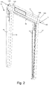
Fig. 2 shows a perspective view seen from above of a screening device according to the first aspect of the invention in a closed position. -
Fig. 3 is a close-up perspective view of a section of the top element of a screening device ofFig. 1 and comprising a connection device. -
Fig. 4 is a perspective view of a connection device of the screening device ofFig. 1 in the assembled state. -
Fig. 5 is an exploded view of the connection device ofFig. 4 showing a receiving element and an adapter element with a first section, a second section and a rod or leg section. -
Fig. 6 is perspective view of the first section of the adapter element of the connection device ofFigs. 4 and5 . -
Fig. 7 is perspective view of the second section and the rod or leg section of the adapter element of the connection device ofFigs. 4 and5 . -
Fig. 8 is a perspective view of a receiving element of the adapter element of the connection device ofFigs. 4 and5 . -
Fig. 9 is a perspective view from another angle of view of the receiving element ofFig. 8 . -
Fig. 10 is a perspective view of a receiving element of the adapter element of the connection device according to the invention mounted on a side rail of a screening device. - The roof window 1 shown in
Fig. 1 is adapted for mounting in an inclined roof. The roof window 1 comprises aframe 2 and anopenable sash 3 supporting aglass pane 12. Thesash 3 may be top hung, center hung or both top hung and center hung, but is in the embodiment shown inFig. 1 top hung. Theframe 2 comprises atop frame member 4, a bottom frame member 5 and two side frame members. Only theside frame member 6 is visible onFig. 1 . Thesash 3 comprises atop sash member 8, abottom sash member 11 and two side sash members. Only theside sash member 9 is visible onFig. 1 . - The roof window 1 further comprises a
screening device 13, which may in principle be any feasible type ofscreening device 13. In one embodiment the screening device is a roller shutter. In other embodiments the screening device may be a roller blind or an awning. - Turning now to
Fig. 2 , an embodiment of ascreening device 13 according to the invention will be described in more detail. Thescreening de-vice 13 generally comprises ascreening body 19, atop element 14, two side covers 15, 16, twoside rails connection device 20. Thetop element 14 comprises opposite ends 141 and 142 withrespective end pieces top element 14 further comprises a longitudinal extension or direction L. It is noted that in principle, the two side covers 15, 16 and/or the twoside rails - The
screening body 19 comprises opposite side sections guided in longitudinal slots of the side rails 17, 18 and is movable between a rolled up position in thetop element 14 and a rolled out position covering thepane 12 of the window 1. Thescreening body 19 may be a one-piece screening body or it may comprise a plurality of slats. - The
screening device 13 may further comprise a bottom element (not shown) and a bottom profile (not shown) arranged extending between the respective side rails 17 and 18 at an end opposite to thetop element 14, as well as a supporting element (not visible) arranged extending in a longitudinal direction L of thetop element 14 between the opposite side covers 15, 16 or side rails 17, 18. It is noted that the bottom element, supporting element and bottom profile are all optional elements which in some embodiments may be omitted. - Turning now to
Fig. 3 , a perspective view of an end section, particularly theend 141 with the end cover 143 (Fig. 2 ) removed, of thetop element 14 of ascreening device 13 according to the invention and comprising aconnection device 20 is shown. Thescreening device 13 more particularly comprises twoconnection devices 20, one at eachlongitudinal end top element 14. As shown, theconnection device 20 is arranged at atop member 4 of theframe 2. Alternatively, theconnection device 20 may be arranged at aside member 5 or 6 of theframe 2. In any event theconnection device 20 connects thescreening device 13 and the window 1 in the mounted condition of thescreening device 13 in such a manner that thescreening device 13 may be displaced to a position in which it forms an angle with the roof window 1. - The
connection device 20 comprises at least one rod-shapedelement 21 provided on thetop element 14 of thescreening device 13. The rod-shapedelement 21 extends in the longitudinal direction L of thetop element 14. The rod-shapedelement 21 further extends in a direction inward from theend top element 14, i.e. away from the end covers 143, 144 (Fig. 2 ) or thesurface 147 of the end piece 145 (Fig. 3 ) In the embodiment shown on the figures there is provided a rod-shapedelement 21 at eachlongitudinal end top element 14. In an alternative embodiment there may be provided one rod-shapedelement 21 extending between the longitudinal ends 141, 142 of thetop element 14. - The
connection device 20 further comprises a receivingelement 23 adapted for being mounted on a side ortop frame member element 23 may be adapted for being integrated in a side ortop frame member top frame member element 23 is adapted for being integrated in aside frame member 5, 6 of the roof window 1, the receivingelement 23 is thus adapted to be mounted adjacent to thetop frame member 4 of the roof window 1. - In other alternative embodiments, the receiving
element 23 may be adapted for being mounted on or integrated in aside rail screening device 13, on or in apart side rail side rail top frame member Fig. 10 . In such embodiments, the receivingelement 23 is thus adapted to be mounted adjacent to a side ortop frame member - Referring to
Fig. 5 , theconnection device 20 further comprises anadapter element 24. Theadapter element 24 comprises afirst part 25 adapted for locking engagement with the receivingelement 23 and asecond part 26 adapted for connection to the rod-shapedelement 21 in such a way that thesecond part 26 is freely rotatable with respect to the rod-shapedelement 21. Thesecond part 26 of theadapter element 24 may be connected to the rod-shapedelement 21 at the factory where the screening device is produced, or alternatively on-site by the person mounting thescreening device 13 on the roof window 1. - Referring particularly to
Fig. 5 , it is clear that the rod-shapedelement 21, theadapter element 24 and the receivingelement 23 are mutually separate elements. - The
adapter element 24 is shown in further detail inFig. 4 showing an assembled state of theconnection device 20,Fig. 5 showing an exploded view andFigs. 6 and 7 showing an exploded view of theadapter element 24. - Referring particularly to
Fig. 7 thefirst part 25 of theadapter element 24 comprises a rod orleg section 27. Theleg section 27 is provided with at least onerecess 270 forming part of a snap-locking mechanism for locking together thefirst part 25 and the receivingelement 23. The other part of this snap-locking mechanism is provided in the form of aslot 28 of the receivingelement 23 and will be described further below. In the embodiment shown, theleg section 27 is provided with twosuch recesses 270 arranged on diametrically opposite sides of theleg section 27. Alternative embodiments include omitting one of the tworecesses 270 or providing one circumferentially extending recess. The rod orleg section 27 may be circular in cross-section such as to achieve an improved taking up of tolerances during the mounting process. - The
first part 25 of theadapter element 24 further comprises afree end 29 opposite thesecond part 26 of theadapter element 24. Theend 29 is adapted for abutting engagement with anend stop 30 provided on the receivingelement 23. Thefree end 29 may be tapered such as to allow for easier insertion of thefirst part 25 of theadapter element 24 into theslot 28 of the receivingelement 23. Also, theslot 28 may be tapering towards a bottom end where theend stop 30 is provided to a geometry and/or shape substantially corresponding to the shape of thefirst part 25, or at least thefree end 29 of thefirst part 25, of theadapter element 24. Theslot 28 may for instance be funnel-shaped. - In some embodiments, the
end 29 may be provided as a magnet or a magnetic material, while theend stop 30 is provided as a magnetic material or a magnet, such as to provide a magnetic locking mechanism for locking together thefirst part 25 and the receivingelement 23. In such an embodiment, the snap-locking mechanism may in principle be omitted. - In some embodiments where the
end 29 is provided as a magnetic material or a magnet, a magnet or a piece of magnetic material may be arranged in theslot 28, particularly at an upper end, i.e. close to the opening, of theslot 28, of the receivingelement 23 such as to attract the magnetic material of theend 29 for easy mating of thefirst part 25 and the receivingelement 23. - Referring to
Fig. 5 , thesecond part 26 of theadapter element 24 comprises afirst section 31 and asecond section 32, both being semi-annular sections. Referring now particularly toFigs. 6 and 7 , The first andsecond section element 21 by being clicked around the rod-shapedelement 21. To this end, thefirst section 31 comprises aprotrusion 33 and aslot 34, and likewise thesecond section 32 comprises aprotrusion 35 and aslot 36. When connecting theadapter element 24 and the rod-shapedelement 21, theprotrusion 33 of thefirst section 31 and theslot 36 of thesecond section 32, respectively theslot 34 of thefirst section 31 and theprotrusion 35 of thesecond section 32, are brought into mutual engagement. A click- or snap-locking connection is enabled in that anose respective protrusion respective slot slot 36 is onFig. 7 denoted 360, while the notch of theslot 34 is denoted 340 onFig. 6 and may be formed by an edge of theslot 34. - In the embodiment shown, the first and
second section inner surface outer surface inner surfaces second sections inner surfaces element 21 in such a way that thesecond part 26, when connected to the rod-shapedelement 21, is freely rotatable with respect to the rod-shapedelement 21. The respectiveouter surfaces - The first and
second section second part 26 of theadapter element 24 may also be provided, such as moulded or cast, in one piece. If the first andsecond section element 23 may be provided as a rod extending from the end piece, and theend cover first part 25 and the receivingelement 23. A separate snap-locking or friction-locking mechanism for locking together thefirst part 25 and the receivingelement 23 may in this case in principle be omitted. Theadapter element 24 and the receivingelement 23 may be connected and the respective end covers 143 and 144 may be mounted on the screening device on-site or at the factory. Thesecond part 26 may further be circular in cross-section such as to achieve an improved taking up of tolerances during the mounting process. - The receiving
element 23 is shown in further detail inFigs. 4 ,8 and9 showing the receivingelement 23 from different angles of view as well as inFig. 5 showing an exploded vies of theconnection device 20. - The receiving
element 23 further comprises the slot 28 (seen best inFig. 8 ) adapted for receiving thefirst part 25 of the adapter element. The slot comprises aresilient member 280 adapted for engaging with therecess 270 provided on theleg section 27 of thefirst part 25 such as to form a snap-locking mechanism for locking together thefirst part 25 and the receivingelement 23. Furthermore, the receivingelement 23 comprises anend stop 30. The end stop is adapted for abutting engagement with theend 29 of theleg section 27 of theadapter element 24. - The snap-locking mechanism for locking together the
first part 25 and the receivingelement 23 may alternatively be provided as a spring mechanism, particularly a substantially omega-shaped spring mechanism comprising two legs and rounded section connected by a narrowed intermediate section. In yet another alternative, the locking mechanism for locking together thefirst part 25 and the receivingelement 23 may be a snap-locking or friction-locking mechanism. Such a friction-locking mechanism may for instance be provided in that the receivingelement 23 is provided as a substantially key-hole shaped opening, and that thefirst part 25 is inserted into the wider part of the receivingelement 23 and slid towards the narrower part of the receivingelement 23 such that the thefirst part 25 and the receivingelement 23 are locked together by friction or snap-locking. - The snap-locking or friction-locking mechanism for locking together the
first part 25 and the receivingelement 23 may be releasable. The snap-locking mechanism may be releasable by means of hand power or by means of a suitable tool. The snap-locking or friction-locking mechanism for locking together thefirst part 25 and the receivingelement 23 may further be biased towards or locked in the locked position such as to avoid undue release of the snap-locking or friction-locking mechanism. - Referring particularly to
Fig. 9 , at an end of theslot 28 opposite theend stop 30, the receivingelement 23 is furthermore provided with astructure 47 adapted for accommodating thesecond section 26 of theadapter element 24 in the assembled condition of theconnection device 20. Thisstructure 47 comprises afirst wall element 42 and asecond wall element 43 spaced apart with a distance d corresponding to the thickness t (cf. alsoFig. 4 ) of thesecond section 26, optionally plus an amount of play, thus allowing easy insertion of theleg section 27 into theslot 28 and easy reception of thesecond section 26 between thewall elements wall elements outs opening 48 formed by the respectiveinner surfaces Fig. 4 ). Thereby, it is ensured that in the assembled state of theconnection device 20, thesecond part 26 remains freely rotatable with respect to the rod-shapedelement 21. - The receiving
element 23 is further provided with one or more holes 41 (Fig. 9 ) adapted for receiving fastening members, such as screws 46 (Fig. 4 ) or the like, such as to attach the receivingelement 23 to aframe member holes 41 may be through or blind. Also, theholes 41 may optionally be provided with a threading. - The
connection device 20 may be made of a suitable metal. Alternatively, theconnection device 20 may be moulded in a suitable plastic material. If theconnection device 20 is moulded in a plastic material, it is even feasible that theconnection device 20 may be moulded in one piece with a moulded frame structure of a roof window 1. In this case it is also possible to omit theholes 41 in the receivingelement 23. - The
respective receiving elements 23,adapter elements 24 and the respective end covers 143 and 144 may be mounted on the screening device on-site or at the factory. - The person skilled in the art realizes that the present invention by no means is limited to the preferred embodiments described above. On the contrary, many modifications and variations are possible within the scope of the appended claims.
-
- 1
- roof window
- 2
- frame
- 3
- sash
- 4
- top frame member
- 5
- bottom frame member
- 6
- side member
- 8
- top sash member
- 9
- side sash member
- 11
- bottom sash member
- 12
- glass pane
- 13
- screening device
- 14
- top element
- 141, 142 opposite ends
- 143, 144 end covers
- 145, 146 end pieces
- 147 surface of
end piece 145
- 15
- side cover
- 16
- side cover
- 17
- side rail
- 18
- side rail
171, 181 part of side rail - 19
- screening body
- 20
- connection device
- 21
- rod-shaped element
- 23
- receiving element
- 24
- adapter element
- 25
- first part
- 26
- second part
- 27
- leg section
270 recesses - 28
- slot
- 29
- end
- 30
- end stop
- 31
- first section
- 32
- second section
- 33
- protrusion
330 nose - 34
- slot
340 notch - 35
- protrusion
350 nose - 36
- slot
360 notch - 37
- semi-circular inner surface
- 38
- semi-circular outer surface
- 39
- semi-circular inner surface
- 40
- semi-circular outer surface
- 41
- holes
- 42
- first wall element
- 43
- second wall element
- 44
- cut-out
- 45
- cut-out
- 46
- screws
- 47
- structure
- 48
- opening
- L
- longitudinal direction
- d
- distance
- t
- thickness
Claims (15)
- A screening device (13) comprising a top element (14) adapted for being mounted on or adjacent to a top frame member (4) of a roof window (1), and
a connection device (20) adapted for connecting the screening device (13) to the roof window (1) on or adjacent to the top frame member (4) of the roof window (1) in such a manner that the screening device (13) may be displaced to a position in which it forms an angle with the roof window (1), wherein
the connection device (20) comprises:a) at least one rod-shaped element (21) provided on the top element (14) and extending in a longitudinal direction (L) of the top element (14),b) a receiving element (23) adapted for being mounted on or adjacent to the top frame member (4) or a side frame member (5, 6) of the roof window (1), and characterized in that the connection device (20) further comprises:c) an adapter element (24) comprising a first part (25) adapted for locking engagement with the receiving element (23) and a second part (26) adapted for connection to the rod-shaped element (21) in such a way that the second part (26) is freely rotatable with respect to the at least one rod-shaped element (21) at least after the first part (25) is brought into engagement with the receiving element (23). - A screening device according to claim 1, wherein the adapter element (24) comprises a first part (25) adapted for locking engagement with the receiving element (23) and a second part (26) adapted for connection to the rod-shaped element (21) in such a way that the second part (26) is freely rotatable with respect to the at least one rod-shaped element (21) both before and after the first part (25) is brought into engagement with the receiving element (23).
- A screening device according to claim 1 or 2, wherein the adapter element (24) is an element being separate from both the rod-shaped element (21) and the receiving element (23).
- A screening device according to any one of the above claims, wherein the second part (26) of the adapter element (24) comprises two sections (31, 32) adapted for being connected with one another around the rod-shaped element (21) in such a manner as to extend all the way around the rod-shaped element (21).
- A screening device according to claim 4, wherein the two sections (31, 32) of the second part (26) of the adapter element (24) are adapted for being connected with one another by a click-connection or a snap-locking connection, and/or
wherein the two sections (31, 32) of the second part (26) of the adapter element (24) are semi-annular sections. - A screening device according to any one of claims 4 to 5, wherein the first part (25) of the adapter element (24) is provided on one of the two sections (31, 32) of the second part (26) of the adapter element (24).
- A screening device according to any one of the above claims, wherein the first part (25) of the adapter element (24) and the receiving element (23) are adapted for mutually forming one of a snap-locking engagement, a friction-locking engagement and a magnet-based locking engagement.
- A screening device according to claim 7, wherein the first part (25) of the adapter element (24) is or comprises a rod or leg section (33), and the receiving element (23) is or comprises a slot (28), or
wherein the first part (25) of the adapter element (24) is or comprises a slot, and the receiving element (23) is or comprises a rod or leg section, or
wherein the first part (25) of the adapter element (24) is or comprises a magnet (29) and the receiving element (23) is or comprises a magnetic material (30), or
wherein the first part (25) of the adapter element (24) is or comprises a magnetic material (29) and the receiving element (23) is or comprises a magnet (30). - A screening device according to any one of the above claims, wherein the first part (25) and the second part (26) of the adapter element (24) is provided in one piece.
- A screening device according to any one of the above claims, wherein the receiving element (23) comprises a first wall element (42) and a second wall element (43), wherein the first wall element (42) and the second wall element (43) are spaced apart with a distance (d) corresponding to at least a thickness (t) of the second section (32), wherein the first wall element (42) and the second wall element (43) each comprise a cut-out (44; 45), and wherein the cut-outs (44; 45) are provided to leave free an opening (48) formed by the second part (26) of the adapter element (24) in the assembled state of the connection device (20).
- A roof window (1) comprising:a stationary frame (2) adapted to be built into a structure and having a top frame member (4), two side frame members (5, 6) and a bottom frame member (7), anda screening device (13) according to any one of the above claims.
- A roof window according to claim 11, wherein the receiving element (23) of the connection device (20) of the screening device (13) is mounted on the top frame member (4) or one of the two side frame members (5, 6) of the roof window (1), or wherein
the receiving element (23) of the connection device (20) of the screening device (13) is integrated in the top frame member (4) or in one of the two side frame members (5, 6) of the roof window (1), or wherein
the receiving element (23) of the connection device (20) of the screening device (13) is mounted on or integrated in a side rail (17, 18) of the screening device (13), on or in a part (171, 181) of the side rail (17, 18) which in a mounted position of the side rail (17, 18) on a roof window (1) is arranged adjacent to one of the two side frame member (5, 6) and/or the top frame member (4) of the roof window (1). - A method for mounting a screening device on a roof window, the method comprising the steps of:a) providing a roof window (1) comprising a stationary frame (2) adapted to be built into a structure and having a top frame member (4), two side frame members (5, 6) and a bottom frame member (7),b) providing a screening device (13) according to any one of claims 1-9,c) mounting the receiving element (23) on or adjacent to, or integrating the receiving element (23) in, the top frame member (4) or one of the two side frame members (5, 6) of the roof window (1), andd) connecting the top element (14) of the screening element (13) with the roof window (1) by connecting the first part (25) of the adapter element (24) hanging from the rod-shaped element (21) to the receiving element (23).
- A method according to claim 13, and comprising the further step of:
e) connecting the second part (26) of the adapter element (24) to the rod-shaped element (21) provided on the top element (14) in such a way that the second part (26) is freely rotatable with respect to the at least one rod-shaped element (21), wherein
step e) is performed before step b) when producing the screening device or after step b) on-site during mounting of the screening device on the roof window. - A method according to claim 14, wherein
step e) is performed by gripping the two sections (31, 32) of the second part (26) from either side of the rod-shaped element (21) and bringing the two sections (31, 32) of the second part (26) into mutual engagement around the rod-shaped element (21) in such a way that the second part (26) is freely rotatable with respect to the at least one rod-shaped element (21), and/or
step d) is performed by inserting the first part (25) of the adapter element (24) into a slot (28) of the receiving element (23).
Applications Claiming Priority (1)
| Application Number | Priority Date | Filing Date | Title |
|---|---|---|---|
| DKPA201970426 | 2019-07-02 |
Publications (2)
| Publication Number | Publication Date |
|---|---|
| EP3760826A2 true EP3760826A2 (en) | 2021-01-06 |
| EP3760826A3 EP3760826A3 (en) | 2021-01-20 |
Family
ID=71108441
Family Applications (1)
| Application Number | Title | Priority Date | Filing Date |
|---|---|---|---|
| EP20180731.0A Pending EP3760826A3 (en) | 2019-07-02 | 2020-06-18 | A screening device, a roof window comprising such a screening device and a method for mounting such a screening device on a roof window |
Country Status (1)
| Country | Link |
|---|---|
| EP (1) | EP3760826A3 (en) |
Cited By (3)
| Publication number | Priority date | Publication date | Assignee | Title |
|---|---|---|---|---|
| DE202021104711U1 (en) | 2021-09-01 | 2021-12-01 | Vkr Holding A/S | External shielding arrangement with light sealing means for a roof window arrangement comprising a plurality of window units |
| DE202021104710U1 (en) | 2021-09-01 | 2021-12-01 | Vkr Holding A/S | External screen assembly with an improved hardware assembly for a multiple window unit skylight assembly |
| DE202021104709U1 (en) | 2021-09-01 | 2021-12-01 | Vkr Holding A/S | External shielding arrangement for a roof window arrangement comprising a plurality of window units |
Citations (4)
| Publication number | Priority date | Publication date | Assignee | Title |
|---|---|---|---|---|
| WO2002006621A1 (en) | 2000-07-13 | 2002-01-24 | Vkr Holding A/S | A screening arrangement |
| DE102005037774B3 (en) | 2005-08-10 | 2007-04-12 | Roma Rolladensysteme Gmbh | Roller window shutter for fitting on an outer side over a window, especially over a roof window, has a window wing to swing out on bearings |
| DE202012010009U1 (en) | 2012-10-19 | 2014-01-20 | Vkr Holding A/S | Window with shielding device with improved fastening devices |
| EP3392443A1 (en) | 2017-04-20 | 2018-10-24 | Roto Frank AG | Roller shutter mounting kit for a roof window, roof window and roller shutter mounted with such kit and method for assembling a roller shutter mounting kit on a roof window |
Family Cites Families (1)
| Publication number | Priority date | Publication date | Assignee | Title |
|---|---|---|---|---|
| DE19600972C1 (en) * | 1996-01-12 | 1997-04-10 | Roto Frank Ag | Shutter for door or window |
-
2020
- 2020-06-18 EP EP20180731.0A patent/EP3760826A3/en active Pending
Patent Citations (4)
| Publication number | Priority date | Publication date | Assignee | Title |
|---|---|---|---|---|
| WO2002006621A1 (en) | 2000-07-13 | 2002-01-24 | Vkr Holding A/S | A screening arrangement |
| DE102005037774B3 (en) | 2005-08-10 | 2007-04-12 | Roma Rolladensysteme Gmbh | Roller window shutter for fitting on an outer side over a window, especially over a roof window, has a window wing to swing out on bearings |
| DE202012010009U1 (en) | 2012-10-19 | 2014-01-20 | Vkr Holding A/S | Window with shielding device with improved fastening devices |
| EP3392443A1 (en) | 2017-04-20 | 2018-10-24 | Roto Frank AG | Roller shutter mounting kit for a roof window, roof window and roller shutter mounted with such kit and method for assembling a roller shutter mounting kit on a roof window |
Cited By (3)
| Publication number | Priority date | Publication date | Assignee | Title |
|---|---|---|---|---|
| DE202021104711U1 (en) | 2021-09-01 | 2021-12-01 | Vkr Holding A/S | External shielding arrangement with light sealing means for a roof window arrangement comprising a plurality of window units |
| DE202021104710U1 (en) | 2021-09-01 | 2021-12-01 | Vkr Holding A/S | External screen assembly with an improved hardware assembly for a multiple window unit skylight assembly |
| DE202021104709U1 (en) | 2021-09-01 | 2021-12-01 | Vkr Holding A/S | External shielding arrangement for a roof window arrangement comprising a plurality of window units |
Also Published As
| Publication number | Publication date |
|---|---|
| EP3760826A3 (en) | 2021-01-20 |
Similar Documents
| Publication | Publication Date | Title |
|---|---|---|
| EP3760826A2 (en) | A screening device, a roof window comprising such a screening device and a method for mounting such a screening device on a roof window | |
| JP5284239B2 (en) | Screen device | |
| WO2013177553A1 (en) | Drawer slide | |
| EP2902572B1 (en) | Device for moving members for operating or for closing a window or door frame | |
| EP3015637A1 (en) | Screening device for a roof window and method for mounting such a screening device on a roof window | |
| JP6787761B2 (en) | Joinery | |
| EP2314355A1 (en) | A self-belay set with two connectors | |
| TWI572771B (en) | The sun shading device and its manufacturing method | |
| CA2834099C (en) | Cordless blind systems having cord enclosures with a swivel feature and methods of assembling such cord enclosures | |
| WO2017089863A1 (en) | Mounting device for a roller blind or the like | |
| JP6001306B2 (en) | Locking device for opening and closing | |
| KR200488839Y1 (en) | The apparatus for opening and closing cabinet door | |
| EP2540929A1 (en) | Folding shutter | |
| CN210858520U (en) | Improved foldable grille system for doors and windows | |
| JP6126422B2 (en) | Joinery | |
| EP3040505A1 (en) | Guide rail assembly | |
| EP2679760B1 (en) | A window with a screening arrangement, and a method for operating the screening arrangement | |
| EP3409873A1 (en) | Tension cord mounting for an architectural covering | |
| EP3363985A1 (en) | Lateral guides | |
| CN214138504U (en) | Tandem pulley and transport device comprising such a tandem pulley | |
| JP6345526B2 (en) | Safety tool | |
| KR101889534B1 (en) | Connecting struture of curtain bar | |
| EP2157265A1 (en) | Window hinge assembly and method of mounting a sash in a frame | |
| EP3130730A1 (en) | Safety catch release mechanism | |
| JP6727646B2 (en) | Pulling device for sliding window |
Legal Events
| Date | Code | Title | Description |
|---|---|---|---|
| PUAI | Public reference made under article 153(3) epc to a published international application that has entered the european phase |
Free format text: ORIGINAL CODE: 0009012 |
|
| STAA | Information on the status of an ep patent application or granted ep patent |
Free format text: STATUS: THE APPLICATION HAS BEEN PUBLISHED |
|
| PUAL | Search report despatched |
Free format text: ORIGINAL CODE: 0009013 |
|
| AK | Designated contracting states |
Kind code of ref document: A2 Designated state(s): AL AT BE BG CH CY CZ DE DK EE ES FI FR GB GR HR HU IE IS IT LI LT LU LV MC MK MT NL NO PL PT RO RS SE SI SK SM TR |
|
| AX | Request for extension of the european patent |
Extension state: BA ME |
|
| AK | Designated contracting states |
Kind code of ref document: A3 Designated state(s): AL AT BE BG CH CY CZ DE DK EE ES FI FR GB GR HR HU IE IS IT LI LT LU LV MC MK MT NL NO PL PT RO RS SE SI SK SM TR |
|
| AX | Request for extension of the european patent |
Extension state: BA ME |
|
| RIC1 | Information provided on ipc code assigned before grant |
Ipc: E06B 9/92 20060101ALI20201217BHEP Ipc: E04D 13/03 20060101ALI20201217BHEP Ipc: E06B 9/42 20060101AFI20201217BHEP |
|
| STAA | Information on the status of an ep patent application or granted ep patent |
Free format text: STATUS: REQUEST FOR EXAMINATION WAS MADE |
|
| 17P | Request for examination filed |
Effective date: 20210621 |
|
| RBV | Designated contracting states (corrected) |
Designated state(s): AL AT BE BG CH CY CZ DE DK EE ES FI FR GB GR HR HU IE IS IT LI LT LU LV MC MK MT NL NO PL PT RO RS SE SI SK SM TR |
|
| GRAP | Despatch of communication of intention to grant a patent |
Free format text: ORIGINAL CODE: EPIDOSNIGR1 |
|
| STAA | Information on the status of an ep patent application or granted ep patent |
Free format text: STATUS: GRANT OF PATENT IS INTENDED |
|
| INTG | Intention to grant announced |
Effective date: 20240313 |
|
| GRAS | Grant fee paid |
Free format text: ORIGINAL CODE: EPIDOSNIGR3 |