EP3760700A1 - Process for treating wort - Google Patents
Process for treating wort Download PDFInfo
- Publication number
- EP3760700A1 EP3760700A1 EP19183785.5A EP19183785A EP3760700A1 EP 3760700 A1 EP3760700 A1 EP 3760700A1 EP 19183785 A EP19183785 A EP 19183785A EP 3760700 A1 EP3760700 A1 EP 3760700A1
- Authority
- EP
- European Patent Office
- Prior art keywords
- wort
- kettle
- gas
- target temperature
- process according
- Prior art date
- Legal status (The legal status is an assumption and is not a legal conclusion. Google has not performed a legal analysis and makes no representation as to the accuracy of the status listed.)
- Granted
Links
- 238000000034 method Methods 0.000 title claims abstract description 91
- 230000008569 process Effects 0.000 title claims abstract description 67
- 239000000203 mixture Substances 0.000 claims abstract description 54
- QMMFVYPAHWMCMS-UHFFFAOYSA-N Dimethyl sulfide Chemical compound CSC QMMFVYPAHWMCMS-UHFFFAOYSA-N 0.000 claims description 79
- 238000009835 boiling Methods 0.000 claims description 68
- 238000010438 heat treatment Methods 0.000 claims description 27
- 238000001704 evaporation Methods 0.000 claims description 16
- 230000008020 evaporation Effects 0.000 claims description 16
- 238000000926 separation method Methods 0.000 claims description 10
- XLYOFNOQVPJJNP-UHFFFAOYSA-N water Substances O XLYOFNOQVPJJNP-UHFFFAOYSA-N 0.000 claims description 8
- 239000007789 gas Substances 0.000 description 53
- 239000000796 flavoring agent Substances 0.000 description 17
- 235000019634 flavors Nutrition 0.000 description 17
- YDBYJHTYSHBBAU-YFKPBYRVSA-N S-methyl-L-methioninate Chemical compound C[S+](C)CC[C@H](N)C([O-])=O YDBYJHTYSHBBAU-YFKPBYRVSA-N 0.000 description 15
- 229960005173 methiosulfonium chloride Drugs 0.000 description 15
- 150000001875 compounds Chemical class 0.000 description 14
- 235000013405 beer Nutrition 0.000 description 10
- 239000011261 inert gas Substances 0.000 description 8
- 239000012071 phase Substances 0.000 description 8
- 102000004169 proteins and genes Human genes 0.000 description 7
- 108090000623 proteins and genes Proteins 0.000 description 7
- GXCLVBGFBYZDAG-UHFFFAOYSA-N N-[2-(1H-indol-3-yl)ethyl]-N-methylprop-2-en-1-amine Chemical compound CN(CCC1=CNC2=C1C=CC=C2)CC=C GXCLVBGFBYZDAG-UHFFFAOYSA-N 0.000 description 6
- 235000013361 beverage Nutrition 0.000 description 6
- 230000015572 biosynthetic process Effects 0.000 description 6
- 238000005345 coagulation Methods 0.000 description 6
- 230000015271 coagulation Effects 0.000 description 6
- 230000002255 enzymatic effect Effects 0.000 description 6
- 239000002253 acid Substances 0.000 description 5
- 238000013124 brewing process Methods 0.000 description 5
- 150000008442 polyphenolic compounds Chemical class 0.000 description 5
- 235000013824 polyphenols Nutrition 0.000 description 5
- 238000012546 transfer Methods 0.000 description 5
- 239000003039 volatile agent Substances 0.000 description 5
- IJGRMHOSHXDMSA-UHFFFAOYSA-N Atomic nitrogen Chemical compound N#N IJGRMHOSHXDMSA-UHFFFAOYSA-N 0.000 description 4
- 150000007513 acids Chemical class 0.000 description 4
- 230000008901 benefit Effects 0.000 description 4
- 239000012159 carrier gas Substances 0.000 description 4
- 230000001419 dependent effect Effects 0.000 description 4
- 239000007788 liquid Substances 0.000 description 4
- 230000009467 reduction Effects 0.000 description 4
- RVBUGGBMJDPOST-UHFFFAOYSA-N 2-thiobarbituric acid Chemical compound O=C1CC(=O)NC(=S)N1 RVBUGGBMJDPOST-UHFFFAOYSA-N 0.000 description 3
- 238000013019 agitation Methods 0.000 description 3
- 238000006243 chemical reaction Methods 0.000 description 3
- 238000000855 fermentation Methods 0.000 description 3
- 230000004151 fermentation Effects 0.000 description 3
- 239000000463 material Substances 0.000 description 3
- 238000012544 monitoring process Methods 0.000 description 3
- 239000011148 porous material Substances 0.000 description 3
- 235000000346 sugar Nutrition 0.000 description 3
- 230000015556 catabolic process Effects 0.000 description 2
- 230000008030 elimination Effects 0.000 description 2
- 238000003379 elimination reaction Methods 0.000 description 2
- 238000005265 energy consumption Methods 0.000 description 2
- 238000005516 engineering process Methods 0.000 description 2
- 239000006260 foam Substances 0.000 description 2
- 230000008642 heat stress Effects 0.000 description 2
- 238000006317 isomerization reaction Methods 0.000 description 2
- 229910052757 nitrogen Inorganic materials 0.000 description 2
- 239000000047 product Substances 0.000 description 2
- 230000000630 rising effect Effects 0.000 description 2
- 229910001220 stainless steel Inorganic materials 0.000 description 2
- 239000010935 stainless steel Substances 0.000 description 2
- 230000001954 sterilising effect Effects 0.000 description 2
- 238000004659 sterilization and disinfection Methods 0.000 description 2
- 102000004190 Enzymes Human genes 0.000 description 1
- 108090000790 Enzymes Proteins 0.000 description 1
- 229920002472 Starch Polymers 0.000 description 1
- 230000001174 ascending effect Effects 0.000 description 1
- QVGXLLKOCUKJST-UHFFFAOYSA-N atomic oxygen Chemical compound [O] QVGXLLKOCUKJST-UHFFFAOYSA-N 0.000 description 1
- 230000036760 body temperature Effects 0.000 description 1
- 239000006227 byproduct Substances 0.000 description 1
- 238000001816 cooling Methods 0.000 description 1
- 230000003247 decreasing effect Effects 0.000 description 1
- 230000003111 delayed effect Effects 0.000 description 1
- 238000004925 denaturation Methods 0.000 description 1
- 230000036425 denaturation Effects 0.000 description 1
- 238000013461 design Methods 0.000 description 1
- 238000011143 downstream manufacturing Methods 0.000 description 1
- 230000000694 effects Effects 0.000 description 1
- 230000002349 favourable effect Effects 0.000 description 1
- 238000011049 filling Methods 0.000 description 1
- 238000001914 filtration Methods 0.000 description 1
- 239000012530 fluid Substances 0.000 description 1
- 230000006872 improvement Effects 0.000 description 1
- 239000007791 liquid phase Substances 0.000 description 1
- 238000012423 maintenance Methods 0.000 description 1
- 230000035800 maturation Effects 0.000 description 1
- 230000000813 microbial effect Effects 0.000 description 1
- 238000002156 mixing Methods 0.000 description 1
- 238000012986 modification Methods 0.000 description 1
- 230000004048 modification Effects 0.000 description 1
- 238000013021 overheating Methods 0.000 description 1
- 239000001301 oxygen Substances 0.000 description 1
- 229910052760 oxygen Inorganic materials 0.000 description 1
- 238000004806 packaging method and process Methods 0.000 description 1
- 230000000149 penetrating effect Effects 0.000 description 1
- 238000001556 precipitation Methods 0.000 description 1
- 239000002243 precursor Substances 0.000 description 1
- 238000012545 processing Methods 0.000 description 1
- 238000010926 purge Methods 0.000 description 1
- 230000005855 radiation Effects 0.000 description 1
- 235000019698 starch Nutrition 0.000 description 1
- 150000008163 sugars Chemical class 0.000 description 1
- 239000010409 thin film Substances 0.000 description 1
- 238000011144 upstream manufacturing Methods 0.000 description 1
Images


Classifications
-
- C—CHEMISTRY; METALLURGY
- C12—BIOCHEMISTRY; BEER; SPIRITS; WINE; VINEGAR; MICROBIOLOGY; ENZYMOLOGY; MUTATION OR GENETIC ENGINEERING
- C12C—BEER; PREPARATION OF BEER BY FERMENTATION; PREPARATION OF MALT FOR MAKING BEER; PREPARATION OF HOPS FOR MAKING BEER
- C12C11/00—Fermentation processes for beer
- C12C11/003—Fermentation of beerwort
-
- C—CHEMISTRY; METALLURGY
- C12—BIOCHEMISTRY; BEER; SPIRITS; WINE; VINEGAR; MICROBIOLOGY; ENZYMOLOGY; MUTATION OR GENETIC ENGINEERING
- C12C—BEER; PREPARATION OF BEER BY FERMENTATION; PREPARATION OF MALT FOR MAKING BEER; PREPARATION OF HOPS FOR MAKING BEER
- C12C7/00—Preparation of wort
- C12C7/20—Boiling the beerwort
-
- C—CHEMISTRY; METALLURGY
- C12—BIOCHEMISTRY; BEER; SPIRITS; WINE; VINEGAR; MICROBIOLOGY; ENZYMOLOGY; MUTATION OR GENETIC ENGINEERING
- C12C—BEER; PREPARATION OF BEER BY FERMENTATION; PREPARATION OF MALT FOR MAKING BEER; PREPARATION OF HOPS FOR MAKING BEER
- C12C13/00—Brewing devices, not covered by a single group of C12C1/00 - C12C12/04
- C12C13/02—Brew kettles
- C12C13/08—Brew kettles with internal heating elements
-
- C—CHEMISTRY; METALLURGY
- C12—BIOCHEMISTRY; BEER; SPIRITS; WINE; VINEGAR; MICROBIOLOGY; ENZYMOLOGY; MUTATION OR GENETIC ENGINEERING
- C12C—BEER; PREPARATION OF BEER BY FERMENTATION; PREPARATION OF MALT FOR MAKING BEER; PREPARATION OF HOPS FOR MAKING BEER
- C12C7/00—Preparation of wort
-
- C—CHEMISTRY; METALLURGY
- C12—BIOCHEMISTRY; BEER; SPIRITS; WINE; VINEGAR; MICROBIOLOGY; ENZYMOLOGY; MUTATION OR GENETIC ENGINEERING
- C12C—BEER; PREPARATION OF BEER BY FERMENTATION; PREPARATION OF MALT FOR MAKING BEER; PREPARATION OF HOPS FOR MAKING BEER
- C12C7/00—Preparation of wort
- C12C7/04—Preparation or treatment of the mash
-
- C—CHEMISTRY; METALLURGY
- C12—BIOCHEMISTRY; BEER; SPIRITS; WINE; VINEGAR; MICROBIOLOGY; ENZYMOLOGY; MUTATION OR GENETIC ENGINEERING
- C12C—BEER; PREPARATION OF BEER BY FERMENTATION; PREPARATION OF MALT FOR MAKING BEER; PREPARATION OF HOPS FOR MAKING BEER
- C12C7/00—Preparation of wort
- C12C7/20—Boiling the beerwort
- C12C7/205—Boiling with hops
- C12C7/22—Processes or apparatus specially adapted to save or recover energy
Definitions
- the present invention relates to an improvement of conventional wort boiling techniques in beer brewing processes.
- it concerns such process which is substantially more economical in terms of energy consumption than hitherto achieved.
- Brewing a beer or a malt based beverage comprises feeding malt to a grinder which is then mixed with water and mashed at a moderately high temperature to promote enzymatic conversion of starches into fermentable sugars.
- the lautering or mash press step the mash is separated into the clear liquid wort and the residual grain.
- the thus separated wort is then fed to a kettle, in a step traditionally referred to as "boiling" step because the wort is conventionally heated above its boiling temperature to sterilize it, terminate enzymatic activity, develop favourable flavour characteristics, and convert and/or remove undesired components.
- trub which has formed during the boiling step is separated from the wort usually in a whirlpool tun, as for example disclosed in DE10 2008 033 287 .
- Wort is then cooled, fermented, matured, filtered and packaged, e.g., in bottles, kegs, cans, and the like.
- Breweries face challenges including the ever-increasing energy prices and complicated transportation due to exportation.
- the increased exportation forces the breweries to search for technological changes that improve the colloidal, microbial and flavour stability.
- Flavour stability is today not yet fully understood. It is known, however, that the wort boiling process has a major impact on beer flavour stability.
- Wort boiling is one of the most energy-consuming process steps in the brewery. Traditionally, the boiling of wort aimed to achieve multiple objectives. As the understanding of the biochemical and physical processes has improved, it has been possible to separate the requirements for each objective and re-visit how these could be achieved in a less energy-intensive process. Traditionally, wort boiling serves the following functions:
- Wort sterilization and termination of enzymatic activity are easily achieved when reaching temperatures of more than 90°C.
- the isomerization rate of hop acids is temperature dependent, roughly doubling every 10°C.
- Denaturation of enzymes and haze-active proteins with subsequent coagulation and precipitation with polyphenols must be completed during the wort boiling process.
- the coagulation process is dramatically enhanced when the interface between liquid and gas is enlarged.
- vapour bubbles provide this extra interface.
- Flavour Formation requires heat and time and is assisted by effective mixing. Removal of unwanted flavour compounds requires mass transfer of the targeted compounds from the wort into an alternative medium in a separation process. Given the volatility of these components one method of separation is to strip them off using a carrier gas. In standard boiling technologies the 'carrier gas' is in fact water vapour from the boiling process itself.
- wort boiling techniques are known in the art.
- the internal boiler is cylindrically shaped formed by a bundle of hollow heated tubes, and wort can freely flow through these tubes.
- the working principle is of the 'thermosyphon' type, whereby wort enters the heating tubes, reaches boiling temperature and vapour bubbles will form and arise. These vapour bubbles (very low density) are the driving force upward through the internal boiler, thereby ensuring a natural convection.
- the boiler can be located outside the kettle and wort is fed therethrough by means of a pump and returned into the kettle. In the last decade numerous new and innovative boiling systems have been introduced.
- wort boiling systems are based on: dynamic wort boiling; thin-film evaporation; external thermosyphon boiler with increased heating surface; continuous wort boiling; vacuum boiling, internal boiler with forced convection; gentle boiling with flash evaporation; and wort boiling with inert gas sparging.
- wort boiling with inert gas sparging consists of boiling wort for a duration of about 30 min at which point, while still boiling, an inert gas is sparged into the boiling wort, which considerably enhances the removal rate of DMS.
- the sparging is provided by a ring-structure located at the bottom of the wort kettle, such as disclosed in EP875560 . Owing to the facilitated DMS removal, the boiling time can be shortened and evaporation rates could be reduced to about 4 wt.%.
- the present invention concerns a process for treating a wort composition in a kettle, said method comprising the steps of:
- the present invention concerns a process for treating a wort composition in a kettle, said method comprising the steps of:
- the present invention concerns a process for treating a wort composition in a kettle, said method comprising the steps of:
- step (d) is referred to as the hot hold step.
- the advantage of this step is that the wort composition undergoes less heat stress and wort damage is minimized at the lower temperature. The reasons for this are twofold: 1) the lower temperature involved reduces the heat stress and wort damage; and 2) the attainment of the target temperature used in steps (e) and (f) is delayed (relative to other prior art processes) allowing a reduced sugar concentration in the kettle, both of which increase shelf-life and flavor stability of the final beverage ( i.e., beer).
- the hot hold step uses 2 to 3 MJ/hl less energy than the traditional boiling process, such as that employed in EP3066185 (0.56 - 0.83 KWh/hl for the present invention versus ⁇ 0.94 kWh/hl for Example 2 of EP3066185 ).
- the process of the invention also uses less energy required for same conversion of S-methylmethionine (SMM) into dimethylsulfide (DMS) (when combined with subsequent standard brewing processes). Furthermore, less sparge gas is required to remove the DMS as much of this has been generated before the sparging commences.
- SMM S-methylmethionine
- DMS dimethylsulfide
- the wort composition in step (c) is heated to the target temperature at a rate of between 0.2°C and 1°C per minute, preferably between 0.4°C and 0.75°C per minute, most preferably about 0.5°C per minute until target temperature is met.
- step (d) preferably the wort composition is heated to the target temperature of step (e) at a rate of between 0.2°C and 1°C per minute, preferably between 0.4°C and 0.75°C per minute, most preferably about 0.5°C per minute until target temperature is met.
- the sparged gas is selected from CO 2 , N 2 and air, and combinations thereof, preferably CO 2 . This is because CO 2 is inert and cheap.
- the byproduct CO 2 generated during the fermentation process in the brewery is used as the sparge gas.
- a surprising aspect of the present invention is the low levels of combined S-methylmethionine (SMM) into dimethylsulfide (DMS) measured immediately at the end of step (f) of the process of the invention.
- SMM S-methylmethionine
- DMS dimethylsulfide
- the wort composition at the end of step (f) contains less than 150 ppb of combined SMM and DMS, more preferably less than 100 ppb, more preferably less than 75 ppb.
- the wort composition exiting step (f) of the process of the invention achieves a DMS (dimethyl sulphide) concentration of less than 150 ppb, more preferably less than 100 ppb, more preferably less than 50 ppb, more preferably less than 20 ppb.
- DMS dimethyl sulphide
- the kettle used in the present invention is preferably heated using a heat exchanger.
- This may be an external wort boiler (EWB).
- the variation (min T to max T) of the temperature in step (f) is T ⁇ 0.75 °C, more preferably T ⁇ 0.5 °C.
- the gas flow in the sparging process of step (f) is uninterrupted.
- any interruption of greater than 10 minutes in the gas sparging process of step (f) should be followed by a continuous gas sparge of not less than 30 minutes. This ensures an adequate removal of volatiles formed during the phase interruption.
- the sparging process of step (f) is constant and uninterrupted.
- the sparging rate of gas does not vary by more than ⁇ 10%, more preferably ⁇ 5% of the average gas sparging rate in step (f).
- the process of the present invention preferably results in less than 2%, more preferably less than 1.5%, more preferably 0.8 - 1.2% evaporation of water based on the weight of the initial wort composition.
- This 2% quantity corresponds to approximately 2MJ/hl, a reduction of 6MJ/hl from a base of 4% and 8MJ/hl from a base of 5% evaporation.
- the process of the present invention is essentially a two-step process
- the first of wort is the process of flavour formation, i.e., the formation of key flavour-active compounds from precursors via chemical reactions which require heat, agitation and time (and may be influenced by pH), and are also dependent on concentration of relevant species.
- Step 2 is the process of volatile stripping, i.e., the removal of volatile flavour-active compounds via mass transfer into a vapour phase provided by a carrier gas, which requires heat, agitation and bubbles, with the bubbles providing the surface area for mass transfer of volatiles into the vapour phase.
- the 'carrier gas' providing the bubbles of the vapour phase is steam generated through boiling of wort.
- volatile stripping is effected entirely by the gas sparging. As such, the need for boiling is unnecessary, as heat, agitation and time are adequately provided.
- the process of the present invention preferably uses a circulation pump.
- the process of the present invention preferably requires the process to target a temperature of at least 1°C below the natural boiling point of the wort composition, at the heater outlet, and preferably no more than a 3°C difference between this heater outlet temperature and the wort bulk temperature in the kettle.
- the object is to bring the wort mass up to temperature without boiling the wort and ensure there is not a large temperature differential between the heat outlet and the wort mass. Normally there is heat loss of the mass of 1-2°C through radiant and loss and gas purging through the wort.
- An internal or an external boiler may be used to transfer the heat to the wort.
- the wort is preferably pumped through the heat exchanger to ensure a flow rate which will allow heat transfer.
- the gas can be sparged into the wort by means of a gas sparger located at or near the bottom of the kettle and oriented upwards or sideways in the radial direction.
- Said sparger preferably comprises a circular plate, cylinder or ring provided with a multitude of apertures.
- the apertures can be orifices or open pores of a sintered material, such as sintered stainless steel.
- the kettle houses a plurality of gas spargers which are spaced apart from one another. This allows a homogeneous sparging of the wort composition to take place. This has the advantage of improving the volatilisation of the undesirable volatile compounds such as DMS.
- the kettle houses at least 4 gas spargers, their apertures being at least 30 cm apart from one another, more preferably at least 50 cm apart.
- the treated wort composition can be transferred to a trub separation step, for example in a whirlpool tun, and then to further treatment vessels to produce a beer or a malt based beverage.
- the beer or malt based beverage thus produced preferably has one or more of the following properties:
- a forced flow across the calandria heating surfaces is preferably maintained throughout the kettle period, from the start of heat-up until heat supply ceases prior to final checks and cast-out. This is easily achieved with a EWB circulation pump. It can also be achieved where an IWB design (internal wort boiler) already incorporates a suitable circulation pump (e.g. Stromboli kettles). In some IWB cases the existing wort cast-out pump is capable of achieving the required circulation.
- the hottest spot in a kettle operation occurs at the exit of the heating means, such as the calandria, which is not necessarily the same as the temperature in the body of the wort. Therefore, it is possible for a temperature differential to develop between the, e.g., calandria exit and the bulk wort, the extent of which would be influenced by the specific configuration of each kettle, including aspects such as: excess heat input to wort passing through calandria; system heat losses; temperature, specific heat capacity and flowrate of the gas used for sparging; vigour of the boil (and hence rate of heat loss through evaporation).
- step (f) the temperature of the bulk wort is kept within 3°C (below) the heater outlet temperature.
- the potential for a temperature differential between the calandria outlet (as the hottest point in the system) and the body of the wort may be even more dramatic with the present process due to the lower heat input into the system.
- it is highly preferable to measure the kettle body temperature / bulk wort temperature ideally at the point expected to be the 'coldest' during kettle operation (e.g. furthest point from return of hot wort ex-calandria into kettle).
- the kettle may contain several temperature monitoring means. These are preferably spaced apart, such that the temperatue of the wort body can be accurately monitored.
- the present invention addresses the wort treatment step following lautering (400) and preceding trub separation (500) such as is most often performed in a whirlpool tun. It is clear that a buffer or pre-heating tank can be interposed between a lautering tun and the kettle (1) without changing anything to the present invention.
- the wort treatment step subject of the present invention is traditionally referred to as a "boiling" step because the wort is traditionally heated above its boiling temperature to sterilize it, terminate enzymatic activity, and convert and/or remove undesired components.
- the term "pseudo-boiling" step is used instead because, contrary to the prior art processes, wort is not brought to its boiling temperature at any moment during the treatment time.
- the pseudo-boiling process of the present invention is meant to replace advantageously the boiling processes disclosed and used to date in the art, with a concomitant substantial reduction of the energy consumption.
- a boiling and a pseudo boiling step
- Boiling water is very energy consuming. Wort physical heat properties are very comparable to those of water.
- VLE vapour-liquid equilibrium
- a kettle (1) which is provided with an inlet (1u) suitable for feeding a wort into the kettle and with an outlet (1d) suitable for flowing the wort out of the kettle.
- Heating means (2) suitable for heating the wort in the kettle must be provided.
- the heating means are generally in the form of a bundle of parallel jacketed hollow tubes, wherein the wort is circulated through the lumen of the hollow tubes which are heated by a heating fluid circulating in the jackets.
- the heating means (2) can be located inside the kettle, thus forming an internal boiler kettle as illustrated in Figure 3(a) . Due to their very low density these vapour bubbles are the driving force upward through the internal boiler, thereby ensuring a natural convection.
- a pump is located below the internal boiler to force wort collected at various points of the kettle to flow through the heating pipes.
- forced convection system is not mandatory in the present invention because, as will be discussed below, the sparged gas bubbles create already a forced convection.
- the heating means (2) can be located outside the kettle, fluidly connected thereto by pipes, thus forming an external boiler kettle as illustrated in Figures 4(a) and 5(a) .
- a pump (8) is usually used to force wort flow through the boiler, Most kettles of the prior art, traditionally used to carry out a wort boiling step fulfill the foregoing requirements,
- the equipment required for the present invention requires a gas sparging system (3) suitable for sparging an inert gas into said wort.
- a gas sparging system can be very simple; and may include a circular plate, cylinder or ring provided with a multitude of apertures. The apertures can be through channels, like in a shower head, or they may be the pores of an open pore structure, such as a sintered material (e.g., sintered stainless steel). If the inert gas used is nitrogen, a nitrogen converter is very simple and inexpensive to install, and if CO 2 is used instead, it is clear that such gas is abundantly available in all breweries.
- the gas sparger (3) is preferably located at the bottom of the kettle, so that the gas bubbles may rise to the surface of the wort, fixing on their way up volatiles and haze active proteins.
- an external boiler kettle is provided with a gas sparging system located at the upstream end of the external boiler with respect to the wort flow direction (in case of Figure 5 , at the bottom of the boiler). The bubbles are forced through the hollow heating tubes (2a) and injected into the kettle together with the wort.
- the sparger be located below the heating tubes (2a) and preferably have a largest dimension (diameter in case of a disc, cylinder, or a ring) which is smaller than the largest diameter of the boiler (2).
- a baffle (5) and a deflector-roof (6) are preferably provided on top of the internal boiler in order to channel the flow of rising gas bubbles and wort, redistribute them over the top liquid-air interface of the wort, and reduce the thickness of the foam thus formed to permit better elimination in the air of the volatiles entrained with the bubbles (cf. Figure 3(b) ).
- Wort is fed to the kettle from a mash separating step, such as a lautering step (400).
- wort is first passed through a buffer or pre-heating tun prior to entering the kettle.
- the temperature of the wort is generally below 80°C,.
- no gas sparging takes place during this phase of the process.
- the temperature of the wort composition is increased to a target temperature of between 98°C and 99°C.
- a gas is sparged through the wort composition at an average rate of 200 g/HI/Hr while maintaining an average target temperature of between 98°C and 99°C for a period of about 60 minutes; and during which the wort composition does not reach its boiling point.
- the wort composition is transferred to a trub separation step.
- this shows an embodiment illustrating the process of a preferred embodiment the present invention.
- the temperature is raised at a rate of 0.6 to 1.2°C/min until the temperature reaches about 3°C below the natural boiling temperature of the wort.
- the wort composition is then enters the "hot stand” phase, where the temperature is maintained at this temperature.
- the temperature is then raised again to about 1.5°C below the natural boiling temperature of the wort, and is held there for a period of time during which the composition is sparged with an inert gas.
- the volatile materials, such as SMM and DMS are stripped from the composition during this part of the process.
- the exit temperature of the external heater is kept above that of the wort body composition. This is because some of the heat is lost to the process (radiation, sparging, etc. ) .
- an inert gas sparger located at the bottom of the kettle generates a column of gas bubbles.
- the volatile components present in the wort are thus in equilibrium between gas and liquid phases without need for the wort to boil.
- the column of bubbles penetrating through the lumens of the hollow tubes of an internal boiler as depicted in Figure 3(b) creates a forced convection independent of temperature, contrary to natural convection which is highly temperature dependent for the creation of sufficient vapour bubbles.
- inert gas bubbles act like vapour bubbles when surfacing, yielding the same effect as with the latter with respect to elimination of volatiles and coagulation of haze active proteins, but without having to boil and evaporate large amounts of wort.
- the gas flow is also advantageous because it homogenizes the wort by creating a gas lift system with a central ascending flow and a lateral descending flow, as illustrated by the black arrows in Figures 3(b) and 4(b) .
- wort can be fed to a whirlpool tun or the like for separating trub from clear wort, and thence proceed to fermentation (700), maturation (800), filtering (900) and packaging (1000) of the thus produced beer exactly in the same way as in the conventional brewing processes.
Abstract
Description
- The present invention relates to an improvement of conventional wort boiling techniques in beer brewing processes. In particular it concerns such process which is substantially more economical in terms of energy consumption than hitherto achieved.
- Brewing a beer or a malt based beverage comprises feeding malt to a grinder which is then mixed with water and mashed at a moderately high temperature to promote enzymatic conversion of starches into fermentable sugars. In the lautering or mash press step, the mash is separated into the clear liquid wort and the residual grain. The thus separated wort is then fed to a kettle, in a step traditionally referred to as "boiling" step because the wort is conventionally heated above its boiling temperature to sterilize it, terminate enzymatic activity, develop favourable flavour characteristics, and convert and/or remove undesired components. After the boiling step, trub which has formed during the boiling step is separated from the wort usually in a whirlpool tun, as for example disclosed in
DE10 2008 033 287 . Wort is then cooled, fermented, matured, filtered and packaged, e.g., in bottles, kegs, cans, and the like. - Breweries face challenges including the ever-increasing energy prices and complicated transportation due to exportation. The increased exportation forces the breweries to search for technological changes that improve the colloidal, microbial and flavour stability. Flavour stability is today not yet fully understood. It is known, however, that the wort boiling process has a major impact on beer flavour stability.
- Wort boiling is one of the most energy-consuming process steps in the brewery. Traditionally, the boiling of wort aimed to achieve multiple objectives. As the understanding of the biochemical and physical processes has improved, it has been possible to separate the requirements for each objective and re-visit how these could be achieved in a less energy-intensive process. Traditionally, wort boiling serves the following functions:
- (a) Wort sterilization,
- (b) Termination of enzymatic activity,
- (c) Isomerization of alpha acids into iso-alpha acids,
- (d) Coagulation of proteins and polyphenols,
- (e) Breakdown of S-methylmethionine (SMM) into dimethylsulfide (DMS),
- (f) Removal of unwanted flavor compounds,
- (g) Flavour formation.
- Wort sterilization and termination of enzymatic activity are easily achieved when reaching temperatures of more than 90°C. The isomerization rate of hop acids is temperature dependent, roughly doubling every 10°C. Denaturation of enzymes and haze-active proteins with subsequent coagulation and precipitation with polyphenols must be completed during the wort boiling process. The coagulation process is dramatically enhanced when the interface between liquid and gas is enlarged. When wort reaches the boiling temperature, vapour bubbles provide this extra interface. Flavour Formation, requires heat and time and is assisted by effective mixing. Removal of unwanted flavour compounds requires mass transfer of the targeted compounds from the wort into an alternative medium in a separation process. Given the volatility of these components one method of separation is to strip them off using a carrier gas. In standard boiling technologies the 'carrier gas' is in fact water vapour from the boiling process itself.
- Breakdown of S-methylmethionine (SMM) to dimethylsulfide (DMS) which is very volatile is a necessary step prior to the evacuation of DMS. The most energy-requiring objective is the removal of unwanted flavour compounds, in particular DMS, but also other flavour compounds. Every volatile is determined by the vapour-liquid-equilibrium (VLE) of the component and wort, the latter being considered physically similar to pure water. This means that a predetermined amount of evaporation is needed to reduce the level of an undesired compound to sub-threshold levels. There is therefore always a minimum evaporation required and most recent systems operate with a minimum of 4-6 wt.% evaporation during the boiling process.
- Increasingly it has become clear that boiling has been a 'means to an end', rather than the end in itself, of achieving a stabilised, (typically) hopped wort ready for further processing before cooling into a fermentation vessel. The most critical of these, in terms of the demands placed on the technology selection, are to ensure the formation of key flavour compounds (an example being formation of DMS from SMM), and the removal of an appropriate proportion of volatile compounds (e.g. DMS) to ensure suitable downstream processing and ultimately the desired organoleptic properties of the final beer.
- Several wort boiling techniques are known in the art. For example, since the 1970's, a commonly applied boiling method is boiling with natural convection by means of an internal boiler. The internal boiler is cylindrically shaped formed by a bundle of hollow heated tubes, and wort can freely flow through these tubes. The working principle is of the 'thermosyphon' type, whereby wort enters the heating tubes, reaches boiling temperature and vapour bubbles will form and arise. These vapour bubbles (very low density) are the driving force upward through the internal boiler, thereby ensuring a natural convection. Alternatively, the boiler can be located outside the kettle and wort is fed therethrough by means of a pump and returned into the kettle. In the last decade numerous new and innovative boiling systems have been introduced. They all focus on energy reduction by decreased evaporation and by reduction of thermal load measured on wort by the thiobarbituric acid (TBA) number method. Examples of modern wort boiling systems are based on: dynamic wort boiling; thin-film evaporation; external thermosyphon boiler with increased heating surface; continuous wort boiling; vacuum boiling, internal boiler with forced convection; gentle boiling with flash evaporation; and wort boiling with inert gas sparging. In particular, wort boiling with inert gas sparging consists of boiling wort for a duration of about 30 min at which point, while still boiling, an inert gas is sparged into the boiling wort, which considerably enhances the removal rate of DMS. The sparging is provided by a ring-structure located at the bottom of the wort kettle, such as disclosed in
EP875560 - The applicant has used gas sparging of wort since 2002. The successful results led to commercial-scale implementation using brewery CO2 as the stripping gas. It was then discovered that compressed air achieved the same results at a lower cost than CO2, with no negative impact on key wort or product quality parameters such as T150 or TBA, provided the air sparging only commenced once the wort was at boiling temperature - the solubility of oxygen being negligible or even non-existent under these conditions. This allowed the applicant to reduce total evaporation from approximately 7% to a maximum of 5%. This concept has now been termed 'Sparge-Assisted Boiling'.
- Even with the latest wort boiling techniques, wort boiling remains the most energy-consuming step of the whole brewing process. There therefore remains in the art a clear need for a more economical treating process of wort issued from a lauter tun. The present invention proposes such process. This and other advantages are presented in the next sections.
- The present invention concerns a process for treating a wort composition in a kettle, said method comprising the steps of:
- (a) providing:
- a kettle provided with an inlet suitable for feeding a wort composition into the kettle and with an outlet suitable for flowing the wort out of the kettle;
- heating means;
- a gas sparging system suitable for sparging a gas into said wort;
- (b) adding wort from a mash separating step into said kettle through the inlet;
- (c) heating said wort to a target temperature between 80 and 96°C;
- (d) maintain an average target temperature between 80 and 96°C for a period of 12-45 minutes, and during which the wort composition does not reach its boiling point, and during which period gas sparging of less than 10 g/HI/Hr, preferably no gas sparging, takes place;
- (e) raising the temperature of the wort composition to a target temperature of between 97°C and 99°C;
- (f) sparging a gas through the wort composition at an average rate of 80-350 g/HI/Hr while maintaining an average target temperature of between 97°C and 99°C for a period of between 15 minutes and 75 minutes; and during which the wort composition does not reach its boiling point; and
- (g) transferring the treated wort composition to a trub separation step through the kettle outlet.
- In a preferred embodiment, the present invention concerns a process for treating a wort composition in a kettle, said method comprising the steps of:
- (a) providing:
- a kettle provided with an inlet suitable for feeding a wort composition into the kettle and with an outlet suitable for flowing the wort out of the kettle;
- heating means;
- a gas sparging system suitable for sparging a gas into said wort;
- (b) adding wort from a mash separating step into said kettle through the inlet;
- (c) heating said wort to a target temperature between 93 and 95.5°C;
- (d) maintaining an average target temperature between 93 and 95.5°C for a period of 15-20 minutes, and during which the wort composition does not reach its boiling point, and during which period substantially no gas sparging takes place;
- (e) raising the temperature of the wort composition to a target temperature of between 97°C and 99°C;
- (f) sparging a gas through the wort composition at an average rate of 120-220 g/HI/Hr while maintaining an average target temperature of between 97°C and 99°C for a period of between 50 minutes and 70 minutes, and during which the wort composition does not reach its boiling point; and
- (g) transferring the treated wort composition to a trub separation step through the kettle outlet.
- In a further preferred embodiment, the present invention concerns a process for treating a wort composition in a kettle, said method comprising the steps of:
- (a) providing:
- a kettle provided with an inlet suitable for feeding a wort composition into the kettle and with an outlet suitable for flowing the wort out of the kettle;
- heating means;
- a gas sparging system suitable for sparging a gas into said wort;
- (b) adding wort from a mash separating step into said kettle through the inlet;
- (c) heating said wort to a target temperature between 94.5 and 95.5°C;
- (d) maintaining an average target temperature between 94.5 and 95.5°C for a period of 15-20 minutes, and during which the wort composition does not reach its boiling point, and during which period no gas sparging takes place;
- (e) raising the temperature of the wort composition to a target temperature of between 98°C and 99°C;
- (f) sparging a gas through the wort composition at an average rate of 190-210 g/HI/Hr while maintaining an average target temperature of between 98°C and 99°C for a period of between 55 minutes and 65 minutes and during which the wort composition does not reach its boiling point; and
- (g) transferring the treated wort composition to a trub separation step through the kettle outlet.
- In any of the above processes, step (d) is referred to as the hot hold step. The advantage of this step is that the wort composition undergoes less heat stress and wort damage is minimized at the lower temperature. The reasons for this are twofold: 1) the lower temperature involved reduces the heat stress and wort damage; and 2) the attainment of the target temperature used in steps (e) and (f) is delayed (relative to other prior art processes) allowing a reduced sugar concentration in the kettle, both of which increase shelf-life and flavor stability of the final beverage (i.e., beer).
-
- The process of the invention also uses less energy required for same conversion of S-methylmethionine (SMM) into dimethylsulfide (DMS) (when combined with subsequent standard brewing processes). Furthermore, less sparge gas is required to remove the DMS as much of this has been generated before the sparging commences. The resultant products exhibit improved shelf life and flavor stability due to lowered temperatures and reduced sugar concentration of the final temperature ramping of step (e).
- In any of the above embodiments, preferably the wort composition in step (c) is heated to the target temperature at a rate of between 0.2°C and 1°C per minute, preferably between 0.4°C and 0.75°C per minute, most preferably about 0.5°C per minute until target temperature is met.
- In any of the above embodiments, once step (d) is completed, preferably the wort composition is heated to the target temperature of step (e) at a rate of between 0.2°C and 1°C per minute, preferably between 0.4°C and 0.75°C per minute, most preferably about 0.5°C per minute until target temperature is met.
- In any of the above embodiments, the sparged gas is selected from CO2, N2 and air, and combinations thereof, preferably CO2. This is because CO2 is inert and cheap. Preferably, the byproduct CO2 generated during the fermentation process in the brewery is used as the sparge gas.
- A surprising aspect of the present invention is the low levels of combined S-methylmethionine (SMM) into dimethylsulfide (DMS) measured immediately at the end of step (f) of the process of the invention. In this regard, while some prior art processes have relatively low levels of DMS, they do not have low levels of SMM. It is important to have low levels of both. Hence, in a particularly preferred embodiment, the wort composition at the end of step (f) contains less than 150 ppb of combined SMM and DMS, more preferably less than 100 ppb, more preferably less than 75 ppb.
- The wort composition exiting step (f) of the process of the invention achieves a DMS (dimethyl sulphide) concentration of less than 150 ppb, more preferably less than 100 ppb, more preferably less than 50 ppb, more preferably less than 20 ppb.
- The kettle used in the present invention is preferably heated using a heat exchanger. This may be an external wort boiler (EWB).
- Preferably, the variation (min T to max T) of the temperature in step (f) is T ± 0.75 °C, more preferably T ± 0.5 °C.
- Preferably, the gas flow in the sparging process of step (f) is uninterrupted. Preferably, any interruption of greater than 10 minutes in the gas sparging process of step (f) should be followed by a continuous gas sparge of not less than 30 minutes. This ensures an adequate removal of volatiles formed during the phase interruption.
- Preferably, the sparging process of step (f) is constant and uninterrupted. Preferably, the sparging rate of gas does not vary by more than ± 10%, more preferably ± 5% of the average gas sparging rate in step (f).
- The process of the present invention preferably results in less than 2%, more preferably less than 1.5%, more preferably 0.8 - 1.2% evaporation of water based on the weight of the initial wort composition. This 2% quantity corresponds to approximately 2MJ/hl, a reduction of 6MJ/hl from a base of 4% and 8MJ/hl from a base of 5% evaporation.
- The process of the present invention is essentially a two-step process, the first of wort is the process of flavour formation, i.e., the formation of key flavour-active compounds from precursors via chemical reactions which require heat, agitation and time (and may be influenced by pH), and are also dependent on concentration of relevant species.
Step 2 is the process of volatile stripping, i.e., the removal of volatile flavour-active compounds via mass transfer into a vapour phase provided by a carrier gas, which requires heat, agitation and bubbles, with the bubbles providing the surface area for mass transfer of volatiles into the vapour phase. - In a traditional boil process, the 'carrier gas' providing the bubbles of the vapour phase is steam generated through boiling of wort. With the present process, volatile stripping is effected entirely by the gas sparging. As such, the need for boiling is unnecessary, as heat, agitation and time are adequately provided.
- The process of the present invention preferably uses a circulation pump.
- The process of the present invention preferably requires the process to target a temperature of at least 1°C below the natural boiling point of the wort composition, at the heater outlet, and preferably no more than a 3°C difference between this heater outlet temperature and the wort bulk temperature in the kettle. The object is to bring the wort mass up to temperature without boiling the wort and ensure there is not a large temperature differential between the heat outlet and the wort mass. Normally there is heat loss of the mass of 1-2°C through radiant and loss and gas purging through the wort.
- An internal or an external boiler may be used to transfer the heat to the wort. In both cases the wort is preferably pumped through the heat exchanger to ensure a flow rate which will allow heat transfer.
- The gas can be sparged into the wort by means of a gas sparger located at or near the bottom of the kettle and oriented upwards or sideways in the radial direction. Said sparger preferably comprises a circular plate, cylinder or ring provided with a multitude of apertures. The apertures can be orifices or open pores of a sintered material, such as sintered stainless steel.
- In a particularly preferred embodiment, the kettle houses a plurality of gas spargers which are spaced apart from one another. This allows a homogeneous sparging of the wort composition to take place. This has the advantage of improving the volatilisation of the undesirable volatile compounds such as DMS. Preferably, the kettle houses at least 4 gas spargers, their apertures being at least 30 cm apart from one another, more preferably at least 50 cm apart.
- At the end of the process step (f), the treated wort composition can be transferred to a trub separation step, for example in a whirlpool tun, and then to further treatment vessels to produce a beer or a malt based beverage. The beer or malt based beverage thus produced preferably has one or more of the following properties:
- (a) Foam stability (NIBEM) of at least 150 s;
- (b) Haze measured on fresh beer or malt based beverage lower than 1.0 EBC; and/or
- (c) Haze measured on beer or malt based beverage aged for 3 days at 60°C lower than 1.5 EBC.
- Where a circulation pump is used, a forced flow across the calandria heating surfaces is preferably maintained throughout the kettle period, from the start of heat-up until heat supply ceases prior to final checks and cast-out. This is easily achieved with a EWB circulation pump. It can also be achieved where an IWB design (internal wort boiler) already incorporates a suitable circulation pump (e.g. Stromboli kettles). In some IWB cases the existing wort cast-out pump is capable of achieving the required circulation.
- It is also important to note that the hottest spot in a kettle operation occurs at the exit of the heating means, such as the calandria, which is not necessarily the same as the temperature in the body of the wort. Therefore, it is possible for a temperature differential to develop between the, e.g., calandria exit and the bulk wort, the extent of which would be influenced by the specific configuration of each kettle, including aspects such as: excess heat input to wort passing through calandria; system heat losses; temperature, specific heat capacity and flowrate of the gas used for sparging; vigour of the boil (and hence rate of heat loss through evaporation).
- In a highly preferred embodiment, during step (f), the temperature of the bulk wort is kept within 3°C (below) the heater outlet temperature.
- In some cases, it may not be possible to measure the temperature at the outlet of an internal heater easily, and as such, monitoring of the temperature in the body of the wort is preferably undertaken. The process of the present invention requires very careful maintenance of the various temperatures used in the process. As such, in-line monitoring of the heating (e.g., calandria) outlet is highly preferred.
- Further, the potential for a temperature differential between the calandria outlet (as the hottest point in the system) and the body of the wort may be even more dramatic with the present process due to the lower heat input into the system. Hence for the present process, it is highly preferable to measure the kettle body temperature / bulk wort temperature, ideally at the point expected to be the 'coldest' during kettle operation (e.g. furthest point from return of hot wort ex-calandria into kettle).
- The kettle may contain several temperature monitoring means. These are preferably spaced apart, such that the temperatue of the wort body can be accurately monitored.
- For a fuller understanding of the nature of the present invention, reference is made to the following detailed description taken in conjunction with the accompanying drawings in which:
-
Figure 1 : shows the various steps of a brewing process; -
Figure 2 : Schematic of process steps of the present invention; -
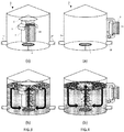
Figure 3 : Shows a first embodiment of an internal boiler kettle suitable for the present invention, (a) empty and (b) filled with wort and with gas being sparged therein; -
Figure 4 : Shows a second embodiment of an external boiler kettle suitable for the present invention, (a) empty and (b) filled with wort and with gas being sparged therein; -
Figure 5 : Shows a third embodiment of an external boiler kettle suitable for the present invention, (a) empty and (b) filled with wort and with gas being sparged therein; and -
Figure 6 : Shows the combined SMM and DMS content of the process of the present invention. - As shown in
Figure 1 , the present invention addresses the wort treatment step following lautering (400) and preceding trub separation (500) such as is most often performed in a whirlpool tun. It is clear that a buffer or pre-heating tank can be interposed between a lautering tun and the kettle (1) without changing anything to the present invention. The wort treatment step subject of the present invention is traditionally referred to as a "boiling" step because the wort is traditionally heated above its boiling temperature to sterilize it, terminate enzymatic activity, and convert and/or remove undesired components. In the present process, however, the term "pseudo-boiling" step is used instead because, contrary to the prior art processes, wort is not brought to its boiling temperature at any moment during the treatment time. - The pseudo-boiling process of the present invention is meant to replace advantageously the boiling processes disclosed and used to date in the art, with a concomitant substantial reduction of the energy consumption. In particular, after both a boiling and a pseudo boiling step:
- (a) The wort must be sterilized,
- (b) the enzymatic activity, must be terminated,
- (c) the amount of alpha acids shall be reduced and replaced by iso-alpha-acids,
- (d) a substantial amount of S-methylmethionine (SMM) must have been transformed into dimethylsulfide (DMS),
- (e) haze active proteins and polyphenols must have been coagulated for separation, and
- (f) unwanted flavour compounds, in particular DMS, shall be removed.
- The above objectives (a) to (d) are mostly time-temperature dependent and can be achieved at temperatures above 80°C, with a rate increasing with the temperature. Coagulation of proteins and polyphenols and removal of unwanted volatile flavour components, on the other hand, are substantially accelerated when the interfacial area between liquid and gas is increased. For this reason, it is necessary to bring the wort to boiling in order to generate vapour bubbles which substantially increase the liquid-gas interfacial area, and hence the coagulation rate of haze active proteins and polyphenols, and removal rate of undesired volatile components. This method of boiling wort to increase the liquid-gas interfacial area works but has two major inconveniences:
- (a) It is strongly energy consuming, and
- (b) Water evaporation ranges from 4 wt.% for the most economical boiling systems, to 6-10 wt.% and more for more traditional boiling techniques.
- Boiling water is very energy consuming. Wort physical heat properties are very comparable to those of water.
- Removal of unwanted volatile flavour compounds such as DMS depends on the vapour-liquid equilibrium (VLE) of each volatile with wort. This means that a determined amount of evaporation is needed to reduce the level of an undesired compound to sub-threshold levels. Therefore a minimum evaporation is always required and most recent systems operate with a minimum of 4-6% evaporation, which is still a considerable amount.
- To carry out a process according to the present invention, a kettle (1) is required, which is provided with an inlet (1u) suitable for feeding a wort into the kettle and with an outlet (1d) suitable for flowing the wort out of the kettle. Heating means (2) suitable for heating the wort in the kettle must be provided. The heating means are generally in the form of a bundle of parallel jacketed hollow tubes, wherein the wort is circulated through the lumen of the hollow tubes which are heated by a heating fluid circulating in the jackets. The heating means (2) can be located inside the kettle, thus forming an internal boiler kettle as illustrated in
Figure 3(a) . Due to their very low density these vapour bubbles are the driving force upward through the internal boiler, thereby ensuring a natural convection. In some systems of the prior art, a pump is located below the internal boiler to force wort collected at various points of the kettle to flow through the heating pipes. Though applicable, such forced convection system is not mandatory in the present invention because, as will be discussed below, the sparged gas bubbles create already a forced convection. Alternatively, the heating means (2) can be located outside the kettle, fluidly connected thereto by pipes, thus forming an external boiler kettle as illustrated inFigures 4(a) and5(a) . A pump (8) is usually used to force wort flow through the boiler, Most kettles of the prior art, traditionally used to carry out a wort boiling step fulfill the foregoing requirements, - The equipment required for the present invention requires a gas sparging system (3) suitable for sparging an inert gas into said wort. Although known in the art, such as disclosed in
EP875560 Figures 3(b) and 4(b) , the gas sparger (3) is preferably located at the bottom of the kettle, so that the gas bubbles may rise to the surface of the wort, fixing on their way up volatiles and haze active proteins. In an alternative embodiment, illustrated inFigure 5(a) & (b) , an external boiler kettle is provided with a gas sparging system located at the upstream end of the external boiler with respect to the wort flow direction (in case ofFigure 5 , at the bottom of the boiler). The bubbles are forced through the hollow heating tubes (2a) and injected into the kettle together with the wort. For kettles of the internal boiler type, it is preferred that the sparger be located below the heating tubes (2a) and preferably have a largest dimension (diameter in case of a disc, cylinder, or a ring) which is smaller than the largest diameter of the boiler (2). With such configuration, the gas bubbles rising through the hollow tubes (2a) of the internal boiler create a forced convection driving wort through the lumens of the hollow tubes of the boiler. This is very advantageous because, on the one hand, no immerged pump is required to create such forced convection and, on the other hand, the flowing rate of the wort through the hollow heating tubes during the heating stage is higher and more homogeneous compared with natural convection systems at temperature below, Tb, when insufficient vapour bubbles are present to create a natural convection with the risk of locally overheating wort. - When a kettle provided with an internal boiler (2) is used, a baffle (5) and a deflector-roof (6) are preferably provided on top of the internal boiler in order to channel the flow of rising gas bubbles and wort, redistribute them over the top liquid-air interface of the wort, and reduce the thickness of the foam thus formed to permit better elimination in the air of the volatiles entrained with the bubbles (cf.
Figure 3(b) ). - Wort is fed to the kettle from a mash separating step, such as a lautering step (400). In some cases, wort is first passed through a buffer or pre-heating tun prior to entering the kettle. The temperature of the wort is generally below 80°C,. After filling the kettle (1) with wort, it is heated to a target temperature of between 94.5 and 95.5°C, and this temperature is maintained for a period of 15 minutes, and during which the wort composition does not reach its boiling point. Preferably, no gas sparging takes place during this phase of the process. After this "holding phase" is carried out, the temperature of the wort composition is increased to a target temperature of between 98°C and 99°C. When this temperature is reached, a gas is sparged through the wort composition at an average rate of 200 g/HI/Hr while maintaining an average target temperature of between 98°C and 99°C for a period of about 60 minutes; and during which the wort composition does not reach its boiling point. Once this step has been completed, the wort composition is transferred to a trub separation step.
- As illustrated in
Figure 2 , this shows an embodiment illustrating the process of a preferred embodiment the present invention. In the first "pre-heating" phase, the temperature is raised at a rate of 0.6 to 1.2°C/min until the temperature reaches about 3°C below the natural boiling temperature of the wort. The wort composition is then enters the "hot stand" phase, where the temperature is maintained at this temperature. The temperature is then raised again to about 1.5°C below the natural boiling temperature of the wort, and is held there for a period of time during which the composition is sparged with an inert gas. The volatile materials, such as SMM and DMS are stripped from the composition during this part of the process. - During all of these process steps, the exit temperature of the external heater is kept above that of the wort body composition. This is because some of the heat is lost to the process (radiation, sparging, etc.).
- As shown in
Figures 3(b) and 4(b) , an inert gas sparger located at the bottom of the kettle generates a column of gas bubbles. The volatile components present in the wort are thus in equilibrium between gas and liquid phases without need for the wort to boil. As discussed above, the column of bubbles penetrating through the lumens of the hollow tubes of an internal boiler as depicted inFigure 3(b) , creates a forced convection independent of temperature, contrary to natural convection which is highly temperature dependent for the creation of sufficient vapour bubbles. On the other hand, inert gas bubbles act like vapour bubbles when surfacing, yielding the same effect as with the latter with respect to elimination of volatiles and coagulation of haze active proteins, but without having to boil and evaporate large amounts of wort. The gas flow is also advantageous because it homogenizes the wort by creating a gas lift system with a central ascending flow and a lateral descending flow, as illustrated by the black arrows inFigures 3(b) and 4(b) . - After the pseudo-boiling process of the present invention, wort can be fed to a whirlpool tun or the like for separating trub from clear wort, and thence proceed to fermentation (700), maturation (800), filtering (900) and packaging (1000) of the thus produced beer exactly in the same way as in the conventional brewing processes.
Claims (14)
- A process for treating a wort composition in a kettle, said method comprising the steps of:(a) providing:a kettle provided with an inlet suitable for feeding a wort composition into the kettle and with an outlet suitable for flowing the wort out of the kettle;heating means;a gas sparging system suitable for sparging a gas into said wort;(b) adding wort from a mash separating step into said kettle through the inlet;(c) heating said wort to a target temperature between 80 and 96°C;(d) maintain an average target temperature between 80 and 96°C for a period of 12-45 minutes, and during which the wort composition does not reach its boiling point, and during which period gas sparging of less than 10 g/HI/Hr, preferably no gas sparging, takes place;(e) raising the temperature of the wort composition to a target temperature of between 97°C and 99°C;(f) sparging a gas through the wort composition at an average rate of 80-350 g/HI/Hr while maintaining an average target temperature of between 97°C and 99°C for a period of between 15 minutes and 75 minutes; and during which the wort composition does not reach its boiling point; and(g) transferring the treated wort composition to a trub separation step through the kettle outlet.
- The process of claim 1, wherein in step (c), the wort is heated to a target temperature between 93 and 95.5°C, preferably between 94.5 and 95.5°C.
- The process according to claim 1 or claim 2, wherein in step (d) the average target temperature is between 93 and 95.5°C preferably between 94.5 and 95.5°C.
- The process according to any preceding claim, wherein the process step (d) is carried out for period of 15-20 minutes.
- The process according to any preceding claim, wherein the process step(d) involves no gas sparging.
- The process according to any preceding claim, wherein the process step (e) comprises raising the temperature of the wort composition to a target temperature of between 97°C and 99°C, preferably between 98°C and 99°C.
- The process according to any preceding claim, wherein the process step (f) comprises sparging a gas through the wort composition at an average rate of 120-220 g/HI/Hr, preferably 190-210 g/HI/Hr, more preferably at about 200 g/HI/Hr.
- The process according to any preceding claim, wherein the process step (f) is carried out for a period of between 55 minutes and 65 minutes, preferably about 60 minutes.
- The process according to any preceding claim, wherein the wort composition in step (c) is heated to the target temperature at a rate of between 0.2°C and 1°C per minute, preferably between 0.4°C and 0.75°C per minute, most preferably about 0.5°C per minute until target temperature is met.
- The process according to any preceding claim, wherein the process step, wherein once step (d) is completed, the wort composition is heated to the target temperature of step (e) at a rate of between 0.2°C and 1°C per minute, preferably between 0.4°C and 0.75°C per minute, most preferably about 0.5°C per minute until target temperature is met.
- The process according to any preceding claim, wherein the sparged gas is selected from CO2, N2 and air, and combinations thereof, preferably CO2.
- The process according to any preceding claim, wherein the wort composition at the end of step (f) contains less than 150 ppb of combined SMM and DMS, more preferably less than 100 ppb, more preferably less than 75 ppb.
- The process according to any preceding claim, wherein the wort composition exiting step (f) of the process of the invention achieves a DMS (dimethyl sulphide) concentration of less than 150 ppb, more preferably less than 100 ppb, more preferably less than 50 ppb, more preferably less than 20 ppb.
- The process according to any preceding claim, wherein the process steps (a) to (f) results in less than 2%, more preferably less than 1.5%, more preferably 0.8 - 1.2% evaporation of water based on the weight of the initial wort composition.
Priority Applications (7)
| Application Number | Priority Date | Filing Date | Title |
|---|---|---|---|
| HUE19183785A HUE064267T2 (en) | 2019-07-02 | 2019-07-02 | Process for treating wort |
| EP19183785.5A EP3760700B8 (en) | 2019-07-02 | 2019-07-02 | Process for treating wort |
| CA3048302A CA3048302C (en) | 2019-07-02 | 2019-07-02 | Process for treating wort |
| RS20230912A RS64673B1 (en) | 2019-07-02 | 2019-07-02 | Process for treating wort |
| HRP20231279TT HRP20231279T1 (en) | 2019-07-02 | 2019-07-02 | Process for treating wort |
| US16/460,039 US11788037B2 (en) | 2019-07-02 | 2019-07-02 | Process for treating wort |
| ES19183785T ES2960337T3 (en) | 2019-07-02 | 2019-07-02 | Procedure to treat must |
Applications Claiming Priority (3)
| Application Number | Priority Date | Filing Date | Title |
|---|---|---|---|
| EP19183785.5A EP3760700B8 (en) | 2019-07-02 | 2019-07-02 | Process for treating wort |
| CA3048302A CA3048302C (en) | 2019-07-02 | 2019-07-02 | Process for treating wort |
| US16/460,039 US11788037B2 (en) | 2019-07-02 | 2019-07-02 | Process for treating wort |
Publications (3)
| Publication Number | Publication Date |
|---|---|
| EP3760700A1 true EP3760700A1 (en) | 2021-01-06 |
| EP3760700B1 EP3760700B1 (en) | 2023-09-20 |
| EP3760700B8 EP3760700B8 (en) | 2023-10-25 |
Family
ID=88469865
Family Applications (1)
| Application Number | Title | Priority Date | Filing Date |
|---|---|---|---|
| EP19183785.5A Active EP3760700B8 (en) | 2019-07-02 | 2019-07-02 | Process for treating wort |
Country Status (3)
| Country | Link |
|---|---|
| US (1) | US11788037B2 (en) |
| EP (1) | EP3760700B8 (en) |
| CA (1) | CA3048302C (en) |
Citations (7)
| Publication number | Priority date | Publication date | Assignee | Title |
|---|---|---|---|---|
| DE2245435A1 (en) * | 1972-09-13 | 1974-03-21 | Alexander Mario Hinz | Pressure brewing kettle - for accelerated browning of beers or wort |
| ZA978962B (en) * | 1996-10-07 | 1998-06-02 | Sapporo Breweries | Method of boiling wort and wort boiling apparatus for realizing the same. |
| EP0875560A1 (en) | 1996-10-07 | 1998-11-04 | Sapporo Breweries Ltd. | Method of boiling wort and wort boiler used therefor |
| EP1420064A1 (en) * | 2002-11-12 | 2004-05-19 | Hrch. Huppmann GmbH | Method for boiling beer wort |
| DE102008033287A1 (en) | 2008-07-11 | 2010-01-14 | Scheuren, Hans, Dipl.-Ing. | Hot trub separation process comprises depletion of undesirable aromas through continuous or discontinuous supply of gas into a wort present in a hot trub separator during the process of hot trub separation |
| DE102011081648A1 (en) * | 2011-08-26 | 2013-02-28 | Krones Ag | Beer brewing process |
| EP2871227A1 (en) * | 2013-11-07 | 2015-05-13 | Anheuser-Busch InBev S.A. | Method for treating a wort in a boiling kettle |
-
2019
- 2019-07-02 CA CA3048302A patent/CA3048302C/en active Active
- 2019-07-02 US US16/460,039 patent/US11788037B2/en active Active
- 2019-07-02 EP EP19183785.5A patent/EP3760700B8/en active Active
Patent Citations (8)
| Publication number | Priority date | Publication date | Assignee | Title |
|---|---|---|---|---|
| DE2245435A1 (en) * | 1972-09-13 | 1974-03-21 | Alexander Mario Hinz | Pressure brewing kettle - for accelerated browning of beers or wort |
| ZA978962B (en) * | 1996-10-07 | 1998-06-02 | Sapporo Breweries | Method of boiling wort and wort boiling apparatus for realizing the same. |
| EP0875560A1 (en) | 1996-10-07 | 1998-11-04 | Sapporo Breweries Ltd. | Method of boiling wort and wort boiler used therefor |
| EP1420064A1 (en) * | 2002-11-12 | 2004-05-19 | Hrch. Huppmann GmbH | Method for boiling beer wort |
| DE102008033287A1 (en) | 2008-07-11 | 2010-01-14 | Scheuren, Hans, Dipl.-Ing. | Hot trub separation process comprises depletion of undesirable aromas through continuous or discontinuous supply of gas into a wort present in a hot trub separator during the process of hot trub separation |
| DE102011081648A1 (en) * | 2011-08-26 | 2013-02-28 | Krones Ag | Beer brewing process |
| EP2871227A1 (en) * | 2013-11-07 | 2015-05-13 | Anheuser-Busch InBev S.A. | Method for treating a wort in a boiling kettle |
| EP3066185A1 (en) | 2013-11-07 | 2016-09-14 | Anheuser-Busch InBev S.A. | Method for treating a wort in a boiling kettle |
Also Published As
| Publication number | Publication date |
|---|---|
| US20210002593A1 (en) | 2021-01-07 |
| EP3760700B8 (en) | 2023-10-25 |
| US11788037B2 (en) | 2023-10-17 |
| CA3048302C (en) | 2023-01-24 |
| EP3760700B1 (en) | 2023-09-20 |
| CA3048302A1 (en) | 2021-01-02 |
Similar Documents
| Publication | Publication Date | Title |
|---|---|---|
| US20230323258A1 (en) | Method for treating a wort in a boiling kettle | |
| AU681128B2 (en) | Improvements in production of fermented malt beverages | |
| AU695392B2 (en) | A process for the continuous boiling of wort | |
| CA2742541A1 (en) | Apparatus and method for stripping wort | |
| US20190177672A1 (en) | Method for producing beer-flavored beverage | |
| EP3760700B1 (en) | Process for treating wort | |
| US20190211290A1 (en) | Method for producing fermented beverage | |
| AU2018271250B2 (en) | Method for producing saccharified moromi | |
| ES2960337T3 (en) | Procedure to treat must | |
| Willaert et al. | Applying sustainable technology for saving primary energy in the brewhouse during beer brewing | |
| JP2015216904A (en) | Manufacturing method of beer-taste beverage, with energy consumption reduced in boiling process | |
| Willaert et al. | Wort boiling today-boiling systems with low thermal stress in combination with volatile stripping | |
| GB2182672A (en) | Process and apparatus for continuous energy saving hop cooking | |
| Muster-Slawitsch et al. | Intensified Brewing Systems |
Legal Events
| Date | Code | Title | Description |
|---|---|---|---|
| REG | Reference to a national code |
Ref country code: HR Ref legal event code: TUEP Ref document number: P20231279T Country of ref document: HR |
|
| PUAI | Public reference made under article 153(3) epc to a published international application that has entered the european phase |
Free format text: ORIGINAL CODE: 0009012 |
|
| STAA | Information on the status of an ep patent application or granted ep patent |
Free format text: STATUS: THE APPLICATION HAS BEEN PUBLISHED |
|
| AK | Designated contracting states |
Kind code of ref document: A1 Designated state(s): AL AT BE BG CH CY CZ DE DK EE ES FI FR GB GR HR HU IE IS IT LI LT LU LV MC MK MT NL NO PL PT RO RS SE SI SK SM TR |
|
| AX | Request for extension of the european patent |
Extension state: BA ME |
|
| STAA | Information on the status of an ep patent application or granted ep patent |
Free format text: STATUS: REQUEST FOR EXAMINATION WAS MADE |
|
| 17P | Request for examination filed |
Effective date: 20210706 |
|
| RBV | Designated contracting states (corrected) |
Designated state(s): AL AT BE BG CH CY CZ DE DK EE ES FI FR GB GR HR HU IE IS IT LI LT LU LV MC MK MT NL NO PL PT RO RS SE SI SK SM TR |
|
| RIC1 | Information provided on ipc code assigned before grant |
Ipc: C12C 13/08 20060101ALI20230206BHEP Ipc: C12C 13/02 20060101ALI20230206BHEP Ipc: C12C 7/22 20060101ALI20230206BHEP Ipc: C12C 7/20 20060101AFI20230206BHEP |
|
| GRAP | Despatch of communication of intention to grant a patent |
Free format text: ORIGINAL CODE: EPIDOSNIGR1 |
|
| STAA | Information on the status of an ep patent application or granted ep patent |
Free format text: STATUS: GRANT OF PATENT IS INTENDED |
|
| INTG | Intention to grant announced |
Effective date: 20230413 |
|
| GRAS | Grant fee paid |
Free format text: ORIGINAL CODE: EPIDOSNIGR3 |
|
| GRAA | (expected) grant |
Free format text: ORIGINAL CODE: 0009210 |
|
| STAA | Information on the status of an ep patent application or granted ep patent |
Free format text: STATUS: THE PATENT HAS BEEN GRANTED |
|
| P01 | Opt-out of the competence of the unified patent court (upc) registered |
Effective date: 20230804 |
|
| AK | Designated contracting states |
Kind code of ref document: B1 Designated state(s): AL AT BE BG CH CY CZ DE DK EE ES FI FR GB GR HR HU IE IS IT LI LT LU LV MC MK MT NL NO PL PT RO RS SE SI SK SM TR |
|
| REG | Reference to a national code |
Ref country code: GB Ref legal event code: FG4D |
|
| RAP4 | Party data changed (patent owner data changed or rights of a patent transferred) |
Owner name: COORS BREWING COMPANY |
|
| REG | Reference to a national code |
Ref country code: CH Ref legal event code: PK Free format text: BERICHTIGUNG B8 Ref country code: CH Ref legal event code: EP |
|
| REG | Reference to a national code |
Ref country code: DE Ref legal event code: R096 Ref document number: 602019037713 Country of ref document: DE |
|
| REG | Reference to a national code |
Ref country code: IE Ref legal event code: FG4D |
|
| REG | Reference to a national code |
Ref country code: LT Ref legal event code: MG9D |
|
| PG25 | Lapsed in a contracting state [announced via postgrant information from national office to epo] |
Ref country code: GR Free format text: LAPSE BECAUSE OF FAILURE TO SUBMIT A TRANSLATION OF THE DESCRIPTION OR TO PAY THE FEE WITHIN THE PRESCRIBED TIME-LIMIT Effective date: 20231221 |
|
| REG | Reference to a national code |
Ref country code: NL Ref legal event code: MP Effective date: 20230920 |
|
| PG25 | Lapsed in a contracting state [announced via postgrant information from national office to epo] |
Ref country code: SE Free format text: LAPSE BECAUSE OF FAILURE TO SUBMIT A TRANSLATION OF THE DESCRIPTION OR TO PAY THE FEE WITHIN THE PRESCRIBED TIME-LIMIT Effective date: 20230920 Ref country code: NO Free format text: LAPSE BECAUSE OF FAILURE TO SUBMIT A TRANSLATION OF THE DESCRIPTION OR TO PAY THE FEE WITHIN THE PRESCRIBED TIME-LIMIT Effective date: 20231220 Ref country code: LV Free format text: LAPSE BECAUSE OF FAILURE TO SUBMIT A TRANSLATION OF THE DESCRIPTION OR TO PAY THE FEE WITHIN THE PRESCRIBED TIME-LIMIT Effective date: 20230920 Ref country code: LT Free format text: LAPSE BECAUSE OF FAILURE TO SUBMIT A TRANSLATION OF THE DESCRIPTION OR TO PAY THE FEE WITHIN THE PRESCRIBED TIME-LIMIT Effective date: 20230920 Ref country code: GR Free format text: LAPSE BECAUSE OF FAILURE TO SUBMIT A TRANSLATION OF THE DESCRIPTION OR TO PAY THE FEE WITHIN THE PRESCRIBED TIME-LIMIT Effective date: 20231221 Ref country code: FI Free format text: LAPSE BECAUSE OF FAILURE TO SUBMIT A TRANSLATION OF THE DESCRIPTION OR TO PAY THE FEE WITHIN THE PRESCRIBED TIME-LIMIT Effective date: 20230920 |
|
| REG | Reference to a national code |
Ref country code: HR Ref legal event code: T1PR Ref document number: P20231279 Country of ref document: HR |
|
| REG | Reference to a national code |
Ref country code: AT Ref legal event code: MK05 Ref document number: 1613423 Country of ref document: AT Kind code of ref document: T Effective date: 20230920 |
|
| REG | Reference to a national code |
Ref country code: HU Ref legal event code: AG4A Ref document number: E064267 Country of ref document: HU |
|
| PG25 | Lapsed in a contracting state [announced via postgrant information from national office to epo] |
Ref country code: NL Free format text: LAPSE BECAUSE OF FAILURE TO SUBMIT A TRANSLATION OF THE DESCRIPTION OR TO PAY THE FEE WITHIN THE PRESCRIBED TIME-LIMIT Effective date: 20230920 |
|
| REG | Reference to a national code |
Ref country code: ES Ref legal event code: FG2A Ref document number: 2960337 Country of ref document: ES Kind code of ref document: T3 Effective date: 20240304 |
|
| PG25 | Lapsed in a contracting state [announced via postgrant information from national office to epo] |
Ref country code: IS Free format text: LAPSE BECAUSE OF FAILURE TO SUBMIT A TRANSLATION OF THE DESCRIPTION OR TO PAY THE FEE WITHIN THE PRESCRIBED TIME-LIMIT Effective date: 20240120 |