EP3760548A1 - A packaging assembly for forming and sealing a plurality of packs containing a pourable product and a method for forming and sealing a plurality of packs - Google Patents
A packaging assembly for forming and sealing a plurality of packs containing a pourable product and a method for forming and sealing a plurality of packs Download PDFInfo
- Publication number
- EP3760548A1 EP3760548A1 EP20180266.7A EP20180266A EP3760548A1 EP 3760548 A1 EP3760548 A1 EP 3760548A1 EP 20180266 A EP20180266 A EP 20180266A EP 3760548 A1 EP3760548 A1 EP 3760548A1
- Authority
- EP
- European Patent Office
- Prior art keywords
- movable
- tube
- packaging assembly
- forming
- respect
- Prior art date
- Legal status (The legal status is an assumption and is not a legal conclusion. Google has not performed a legal analysis and makes no representation as to the accuracy of the status listed.)
- Granted
Links
Images





Classifications
-
- B—PERFORMING OPERATIONS; TRANSPORTING
- B65—CONVEYING; PACKING; STORING; HANDLING THIN OR FILAMENTARY MATERIAL
- B65B—MACHINES, APPARATUS OR DEVICES FOR, OR METHODS OF, PACKAGING ARTICLES OR MATERIALS; UNPACKING
- B65B55/00—Preserving, protecting or purifying packages or package contents in association with packaging
- B65B55/02—Sterilising, e.g. of complete packages
- B65B55/04—Sterilising wrappers or receptacles prior to, or during, packaging
- B65B55/10—Sterilising wrappers or receptacles prior to, or during, packaging by liquids or gases
-
- B—PERFORMING OPERATIONS; TRANSPORTING
- B65—CONVEYING; PACKING; STORING; HANDLING THIN OR FILAMENTARY MATERIAL
- B65B—MACHINES, APPARATUS OR DEVICES FOR, OR METHODS OF, PACKAGING ARTICLES OR MATERIALS; UNPACKING
- B65B9/00—Enclosing successive articles, or quantities of material, e.g. liquids or semiliquids, in flat, folded, or tubular webs of flexible sheet material; Subdividing filled flexible tubes to form packages
- B65B9/10—Enclosing successive articles, or quantities of material, in preformed tubular webs, or in webs formed into tubes around filling nozzles, e.g. extruded tubular webs
- B65B9/20—Enclosing successive articles, or quantities of material, in preformed tubular webs, or in webs formed into tubes around filling nozzles, e.g. extruded tubular webs the webs being formed into tubes in situ around the filling nozzles
- B65B9/207—Enclosing successive articles, or quantities of material, in preformed tubular webs, or in webs formed into tubes around filling nozzles, e.g. extruded tubular webs the webs being formed into tubes in situ around the filling nozzles the web advancing continuously
-
- B—PERFORMING OPERATIONS; TRANSPORTING
- B65—CONVEYING; PACKING; STORING; HANDLING THIN OR FILAMENTARY MATERIAL
- B65B—MACHINES, APPARATUS OR DEVICES FOR, OR METHODS OF, PACKAGING ARTICLES OR MATERIALS; UNPACKING
- B65B51/00—Devices for, or methods of, sealing or securing package folds or closures; Devices for gathering or twisting wrappers, or necks of bags
- B65B51/10—Applying or generating heat or pressure or combinations thereof
- B65B51/22—Applying or generating heat or pressure or combinations thereof by friction or ultrasonic or high-frequency electrical means
- B65B51/225—Applying or generating heat or pressure or combinations thereof by friction or ultrasonic or high-frequency electrical means by ultrasonic welding
-
- B—PERFORMING OPERATIONS; TRANSPORTING
- B65—CONVEYING; PACKING; STORING; HANDLING THIN OR FILAMENTARY MATERIAL
- B65B—MACHINES, APPARATUS OR DEVICES FOR, OR METHODS OF, PACKAGING ARTICLES OR MATERIALS; UNPACKING
- B65B51/00—Devices for, or methods of, sealing or securing package folds or closures; Devices for gathering or twisting wrappers, or necks of bags
- B65B51/10—Applying or generating heat or pressure or combinations thereof
- B65B51/22—Applying or generating heat or pressure or combinations thereof by friction or ultrasonic or high-frequency electrical means
- B65B51/227—Applying or generating heat or pressure or combinations thereof by friction or ultrasonic or high-frequency electrical means by induction welding
-
- B—PERFORMING OPERATIONS; TRANSPORTING
- B65—CONVEYING; PACKING; STORING; HANDLING THIN OR FILAMENTARY MATERIAL
- B65B—MACHINES, APPARATUS OR DEVICES FOR, OR METHODS OF, PACKAGING ARTICLES OR MATERIALS; UNPACKING
- B65B51/00—Devices for, or methods of, sealing or securing package folds or closures; Devices for gathering or twisting wrappers, or necks of bags
- B65B51/10—Applying or generating heat or pressure or combinations thereof
- B65B51/26—Devices specially adapted for producing transverse or longitudinal seams in webs or tubes
- B65B51/30—Devices, e.g. jaws, for applying pressure and heat, e.g. for subdividing filled tubes
-
- B—PERFORMING OPERATIONS; TRANSPORTING
- B65—CONVEYING; PACKING; STORING; HANDLING THIN OR FILAMENTARY MATERIAL
- B65B—MACHINES, APPARATUS OR DEVICES FOR, OR METHODS OF, PACKAGING ARTICLES OR MATERIALS; UNPACKING
- B65B61/00—Auxiliary devices, not otherwise provided for, for operating on sheets, blanks, webs, binding material, containers or packages
- B65B61/04—Auxiliary devices, not otherwise provided for, for operating on sheets, blanks, webs, binding material, containers or packages for severing webs, or for separating joined packages
- B65B61/06—Auxiliary devices, not otherwise provided for, for operating on sheets, blanks, webs, binding material, containers or packages for severing webs, or for separating joined packages by cutting
-
- B—PERFORMING OPERATIONS; TRANSPORTING
- B65—CONVEYING; PACKING; STORING; HANDLING THIN OR FILAMENTARY MATERIAL
- B65B—MACHINES, APPARATUS OR DEVICES FOR, OR METHODS OF, PACKAGING ARTICLES OR MATERIALS; UNPACKING
- B65B9/00—Enclosing successive articles, or quantities of material, e.g. liquids or semiliquids, in flat, folded, or tubular webs of flexible sheet material; Subdividing filled flexible tubes to form packages
- B65B9/06—Enclosing successive articles, or quantities of material, in a longitudinally-folded web, or in a web folded into a tube about the articles or quantities of material placed upon it
- B65B9/08—Enclosing successive articles, or quantities of material, in a longitudinally-folded web, or in a web folded into a tube about the articles or quantities of material placed upon it in a web folded and sealed transversely to form pockets which are subsequently filled and then closed by sealing
-
- B—PERFORMING OPERATIONS; TRANSPORTING
- B65—CONVEYING; PACKING; STORING; HANDLING THIN OR FILAMENTARY MATERIAL
- B65B—MACHINES, APPARATUS OR DEVICES FOR, OR METHODS OF, PACKAGING ARTICLES OR MATERIALS; UNPACKING
- B65B9/00—Enclosing successive articles, or quantities of material, e.g. liquids or semiliquids, in flat, folded, or tubular webs of flexible sheet material; Subdividing filled flexible tubes to form packages
- B65B9/10—Enclosing successive articles, or quantities of material, in preformed tubular webs, or in webs formed into tubes around filling nozzles, e.g. extruded tubular webs
- B65B9/20—Enclosing successive articles, or quantities of material, in preformed tubular webs, or in webs formed into tubes around filling nozzles, e.g. extruded tubular webs the webs being formed into tubes in situ around the filling nozzles
- B65B9/2049—Package shaping devices acting on filled tubes prior to sealing the filling opening
-
- B—PERFORMING OPERATIONS; TRANSPORTING
- B65—CONVEYING; PACKING; STORING; HANDLING THIN OR FILAMENTARY MATERIAL
- B65D—CONTAINERS FOR STORAGE OR TRANSPORT OF ARTICLES OR MATERIALS, e.g. BAGS, BARRELS, BOTTLES, BOXES, CANS, CARTONS, CRATES, DRUMS, JARS, TANKS, HOPPERS, FORWARDING CONTAINERS; ACCESSORIES, CLOSURES, OR FITTINGS THEREFOR; PACKAGING ELEMENTS; PACKAGES
- B65D65/00—Wrappers or flexible covers; Packaging materials of special type or form
- B65D65/02—Wrappers or flexible covers
- B65D65/16—Wrappers or flexible covers with provision for excluding or admitting light
Definitions
- the present invention relates to a packaging assembly configured to form and seal a plurality of packs containing a pourable product, in particular a pourable food product.
- the present invention also relates to a method for forming and sealing a plurality of packs containing a pourable product, in particular a pourable food product.
- pourable food products such as fruit juice, UHT (ultra-high temperature-treated) milk, wine, tomato sauce, etc.
- UHT ultra-high temperature-treated milk
- wine tomato sauce
- etc. are sold in packages made of sterilized packaging material.
- a typical example is the parallelepiped-shaped package for pourable food products known as Tetra Brik Aseptic (registered trademark), which is made by folding and sealing a laminated web of packaging material.
- the packaging material has a multilayer structure comprising a base layer, e.g. made of paper, covered on both sides with layers of heat-seal plastic material, e.g. polyethylene.
- the packaging material also comprises a layer of oxygen-barrier material, e.g. an aluminum foil, which is superimposed on a layer of heat-seal plastic material, and is in turn covered with another layer of heat-seal plastic material forming the inner face of the package eventually contacting the food product.
- Such packages are normally produced in fully automatic packaging assemblies, in which a continuous tube is formed from a web of packaging material fed to such packaging assembly.
- the web of packaging material is sterilized in the packaging assembly, e.g. by applying a chemical sterilizing agent, such as hydrogen peroxide solution, which, once sterilization is completed, is removed from the surfaces of the packaging material, e.g. evaporated by heating.
- a chemical sterilizing agent such as hydrogen peroxide solution
- the tube is filled with the sterilized food product from above and is sealed and subsequently cut along equally spaced transversal cross sections.
- Pillow packs are obtained thereby, which have a longitudinal sealing band, a top transversal sealing band and a bottom transversal sealing band.
- packaging assemblies comprising a plurality of carts movable independently from each other on tracks and configured to form and seal the above-mentioned pillow packs.
- a typical packaging assembly comprises two conveyors provided with:
- the first carts are movable (controllable) independently from one another along the first path
- the second carts are movable (controllable) independently from one another along the second path.
- linear motors are typically used.
- each one of the first track and second track is equipped with respective individually-excitable solenoids, e.g. electric coils, whilst each one of the first carts and second carts is equipped with permanent magnets.
- the resulting linear motor is configured to independently control, in a known manner, the advancement of the first carts and second carts respectively along the first path and second path.
- the first carts and the second carts are configured to cyclically cooperate with one another in pairs and with the tube so as to form and seal respective tube portions of the tube, thereby producing the above-mentioned pillow packs.
- the known packaging assemblies are still open to further improvement.
- a need is felt to optimize the known packaging assemblies when handling, i.e. forming and sealing, packs configured to be folded so as to form packages having a slanted (non-horizontal) top wall, such as the Tetra Brik (registered trademark) Edge package.
- number 1 indicates as a whole a packaging assembly configured to form and seal a plurality of packs 3 containing a pourable product, preferably a pourable food product, starting from a tube 2 of packaging material.
- the packaging material has a multilayer structure (not shown), and comprises a layer of fibrous material, e.g. paper, covered on both sides with respective layers of heat-seal plastic material, e.g. polyethylene.
- the packaging material also comprises a layer of gas-and-light barrier material, e.g. aluminum foil or ethylene vinyl alcohol (EVOH) film, which is superimposed on a layer of heat-seal plastic material, and is in turn covered with another layer of heat-seal plastic material, the latter forming the inner face of the pack 3 eventually contacting the pourable product.
- gas-and-light barrier material e.g. aluminum foil or ethylene vinyl alcohol (EVOH) film
- Tube 2 is formed in known manner by longitudinally folding and sealing a web (not shown) of packaging material. Tube 2 is then filled from above by a pipe (not shown) with the pourable product and is fed through packaging assembly 1 along a straight advancing direction A. In detail, tube 2 extends along a straight longitudinal, in particular vertical, axis X parallel to direction A.
- Packaging assembly 1 comprises:
- each conveyor 4 substantially comprises:
- each cart 7 is configured to cyclically slide along track 6 of the respective conveyor 4. In light of the above, a plurality of carts 7 slides, in use, along each track 6.
- each cart 7 substantially comprises ( Figures 2 and 3 ) a movable body 14, which extends parallel to direction C, when coupled to the respective track 6, and which is provided with a plurality of wheels 15 configured to movably engage the respective track 6.
- carts 7 of one conveyor 4 are movable along the respective track 6 independently from one another and from the carts 7 of the other conveyor 4.
- each cart 7 is provided with a magnetic portion, in particular a permanent magnet arrangement 11, and each conveyor 4 comprises a plurality of electrically-supplied magnetic field generators, preferably electric coils 12, arranged within box-shaped element 5 in fixed positions. Coils 12 are configured to be magnetically coupled with permanent magnet 11 of each cart 7, so as to control the movement of such cart 7 along the respective track 6.
- permanent magnets arrangements 11 and coils 12 - i.e. carts 7 and the respective track 6 - of each conveyor 4 define a linear motor, which, in a known manner, is configured to independently control the movement of carts 7 along the respective track 6.
- tracks 6 of the two conveyors 4 may include one single rail.
- the two tracks 6 define respective endless paths P, Q arranged on opposite sides of axis X of tube 2 with respect to direction B. More specifically, paths P, Q comprise:
- paths P, Q are substantially oval-shaped.
- each cart 7 of one conveyor 4 cooperates with a corresponding cart 7 of the other conveyor 4 - i.e. carts 7 mutually cooperates two by two - defining in this way a pair of carts 7 facing each other and cooperating with one another and with tube 2 while sliding along operative branches P1, Q1.
- each pair of carts 7 is configured to cooperate with tube 2 in order to cyclically form and seal one respective pillow pack 3 at a time, and cut the pillow pack 3 to separate the pillow pack 3 from tube 2, as shown in Figure 1 .
- each cart 7 carries, at one of its sides, a forming unit 18 and a sealing unit 19 both configured to cooperate with tube 2 along the respective operative branches P1, Q1.
- forming units 18 are configured to respectively cooperate with tube portions 13 of tube 2 to form at least corresponding pack portions, more in particular corresponding packs 3.
- each forming unit 18 is carried by, preferably mounted on, the respective cart 7 in a movable manner and comprises a respective forming member, preferably a half-shell 20, presenting a C-shaped cross section and comprising a main wall 21 and a pair of lateral flaps 22.
- flaps 22 are movably coupled to wall 21.
- flaps 22 project from opposite lateral edges of wall 21, with respect to direction C when carts move along operative branches P1, Q1, and are hinged to such edges.
- each forming unit 18 is configured to sequentially and cyclically cooperate in contact with tube portions 13 so as to form at least pack portions of respective packs 3.
- each half-shell 20 is linearly movable transversally, in particular orthogonally, to direction A and axis X, towards tube 2, i.e. towards the tube portion 13 that half-shell 20 has to form.
- each cart 7 comprises a movable element 57 linearly movable transversally, in particular orthogonally, to direction A and axis X, which carries a respective half shell 20.
- movable element 57 is linearly movable along direction B.
- Sealing units 19 are configured to cooperate with tube 2 to seal tube portions 13 at predetermined, equally spaced, successive cross sections crosswise to direction A and located on a sealing plane S parallel to direction A and centered with respect to tube 2, in order to sequentially form opposite top sealing band 3a and bottom sealing band 3b in each tube portion 13.
- sealing plane S axially intersects tube 2 and contains axis X.
- sealing units 19 are configured to cooperate with tube 2 to cut such packs 3 at the cross sections through the top sealing band 3a and bottom sealing band 3b, so as to separate packs 3 from one another.
- each sealing unit 19 is mounted downstream of the corresponding forming unit 18 of the respective cart 7 along the respective path P, Q and comprises a counter-sealing device 17 and an extractable cutting element, for example a knife (not shown).
- each sealing unit 19 is mounted downstream of the corresponding forming unit 18 of the respective cart 7 along the respective path P, Q and comprises a sealing device 23 and a non-shown seat, adapted to receive the knife of the corresponding sealing device 23 configured to cooperate with such counter-sealing device 17.
- sealing devices 23 are ultrasonic sealing devices.
- sealing devices 23 are inductive heating elements and the corresponding counter-sealing devices 17 are made of elastomeric material, which provides the necessary mechanical support to grip tube 2 to the required pressure during sealing operation.
- flaps 22 of each half-shell 20 rotate about the respective hinges from a position in which they diverge from the respective wall 21, to a position in which they are substantially orthogonal to the wall 21, face flaps 22 of the other half-shell 20 carried by the corresponding cart 7 of the same pair and contact tube 2 to completely surround the respective tube portion 13 destined to form the respective pack 3.
- the respective cutting element is extracted, so as to cut packs 3 between top sealing band 3a (of one package) and bottom sealing band 3b (of an adjacent package) and separate formed packs 3 from one another.
- the above-mentioned cyclic movement of half-shells 20 (walls 21 and flaps 22), counter-sealing devices 17, sealing devices 23 and cutting elements from their idle positions to their operative positions is automatized (in a manner known per se and not described in detail) by cooperation between a cam assembly 24 ( Figure 2 ), fixed with respect to the conveyors 4 and tracks 6, and a plurality of cam followers (partially shown in Figure 2 ) carried by each cart 7.
- each one of the walls 21, flaps 22, sealing devices 23, cutting elements and counter-sealing devices 17 carries at least one respective cam follower configured to cooperate in a sliding manner with a respective cam surface of the cam assembly 24.
- flaps 22 of each forming unit 18 carry a respective cam follower 25 configured to cooperate in a sliding manner with a corresponding cam surface of a cam element 26 of the cam assembly 24.
- cam followers 25 are configured to cooperate in a sliding manner with the respective cam elements 26 to be moved transversally to advancement direction A, while carts 7 move, in use, along operative branches P1, Q1.
- cam follower 25 is mechanically connected (coupled) to flaps 22 by means of a lever mechanism 27 ( Figure 3 ) which is configured to drive the rotation of flaps 22 about their hinges in a known manner, due to interaction of cam follower 25 with cam element 26.
- half-shells 20, counter-sealing devices 17, sealing devices 23 and cutting elements are pushed back towards their respective idle positions by springs (not shown), which act on the respective cam followers.
- Outlet conveyor 10 is configured to receive and convey pillow packs 3 towards a non-shown folding unit, in which packs 3 are folded into their final shapes, thereby obtaining respective packages 50 (one of which shown in Figure 7a ).
- Figure 7b shows a pillow pack 3 which does not correspond to any step of the forming cycle.
- Figure 7b merely shows a package 50 with its flaps opened and top sealing band 3a and bottom sealing band 3b raised (i.e. a package 50 not fully folded).
- pillow packs 3 comprise a substantially prismatic main portion 51 having a longitudinal axis Y and being delimited at its bottom end by a flat horizontal bottom wall 52 and at its top end by a slanted top wall 53.
- Top sealing band 3a and bottom sealing band 3b formed by sealing units 19 in the manner described above, protrude axially from slanted top wall 53 and bottom wall 52, respectively.
- Edge package - bottom sealing band 3b is coaxial to axis Y, whereas top sealing band 3a is off-centered with respect to axis Y.
- top sealing band 3a protrudes vertically from slanted top wall 53, as visible in Figure 7b , it is arranged offset with respect to axis Y by a distance 55 (measured orthogonally to axis Y).
- sealing units 19 are configured to cooperate with tube 2 to seal tube portions 13 at cross sections located on sealing plane S, which is centered with respect to tube 2, and since top sealing band 3a is arranged on slanted top wall 53 of package 50 offset with respect to axis Y so as to ensure the formation of slanted top wall 53, a slight rotation of tube portions 13 occurs during the sealing operation.
- Such a rotation is imparted during the sealing operation due to the particular pre-determined pattern of the crease lines (known per se and not shown) provided on the packaging material and necessary to determine the forming of package 50 with slanted top wall 53.
- each half-shell 20 is tiltable with respect to direction A, to control a tilting of the respective tube portion 13 with respect to direction A.
- each half-shell 20 is tiltable with respect to the respective movable element 57.
- half-shell 20 comprises a back wall 56 connected to movable element 57 and movably carrying wall 21 - and, through this wall 21, flaps 22 - and linearly movable towards said tube 2 along direction B.
- each back wall 56 is arranged behind the respective wall 21 with respect to direction B.
- each wall 21 is tiltable with respect to the respective back wall 56, which does not tilt, but only moves linearly along direction B.
- walls 21 of each pair of half-shells 20 are tiltable of angles ⁇ with respect to direction A and with respect to back walls 56 ( Figure 5b ), in order to drive the tilting of the same angle ⁇ of the tube portions 13 they are cooperating with.
- walls 21 are both linearly movable along direction B, carried by back walls 56, and tiltable of the angle ⁇ with respect to direction A.
- flaps 22 are hinged to walls 21, also flaps 22 are tiltable with respect to the respective back walls 56.
- walls 21 are configured to be tilted while carts 7 are advancing parallel to direction A, in detail along operative branches P1, Q1 of endless paths P, Q, respectively.
- the above configuration ensures that the top sealing band 3a of each package 50 is formed offset of the distance 55 with respect to the axis Y of the package 50, without compromising the structural integrity of the package 50.
- packaging assembly 1 comprises actuator means configured to drive the tilting movement of each wall 21, and therefore of each tube portion 13.
- actuator means comprise cam follower 25 and cam element 26.
- cart 7 comprises a pusher mechanism 28 to which cam follower 25 is fitted and which is configured to cooperate in contact with half-shell 20 to drive the tilting movement of wall 21.
- wall 21 is movably coupled to back wall 56 of half-shell 20 by means of a hinge 29 ( Figures 4 , 5a , and 5b ) configured to allow a rotation of wall 21 about direction C with respect to back wall 56.
- Pusher mechanism 28 comprises a pushing pin 30 coupled to cam follower 25, in particular integrally fixed to cam follower 25 so that to a transversal movement of cam follower 25 along direction B and towards axis X, corresponds a transversal movement of pushing pin 30 along direction B and towards axis X.
- Pushing pin 30 is arranged behind back wall 56 and wall 21 of half-shell 20, with respect to direction B when cart 7 advances along operative branch P1 or Q1, and is configured to push onto wall 21 to drive the rotation of wall 21 about its hinge 29, thereby controlling the tilting movement of angle ⁇ of wall 21 and, therefore, of the respective tube portion 13.
- back wall 56 is provided with a through hole ( Figures 5a-5b ) through which pushing pin 30 passes, in use, before reaching wall 21.
- cart 7 comprises a stopping member 31 configured to stop the movement of the lever mechanism 27 controlling the rotation of flaps 22, while allowing an extra-stroke of pusher mechanism 28, and therefore of pin 30, along direction B.
- stopping member 31 is configured to abut on an abutment surface of cart 7 as soon as flaps 22 reach their final positions surrounding tube portion 13.
- wall 21 and tube portion 13 are movable between:
- elastic means are provided, for example a spring member 32 elastically coupling wall 21 to back wall 56.
- spring member 32 is arranged on the opposite side of wall 21 with respect to the side hinge 29 is arranged at, with respect to direction A.
- a first half-shell 20 of the couple of half-shells has a wall 21 that is hinged to an upper portion of the respective back wall 56 (with respect to direction A) and a second half-shell 20 of the couple of half-shells has a wall 21 that is hinged to a lower portion of back wall 56 (with respect to direction A).
- each forming unit 18 is movable towards the respective sealing unit 19 of each cart 7 along direction A, in a manner known and not described in detail. Such movement allows the forming of slanted top wall 53 and bottom wall 54.
- packaging assembly 1 The operation of packaging assembly 1 is described hereafter starting from a condition in which a pair of cooperating carts 7 slide along the respective tracks 6, following the respective paths P, Q and approaching the respective operative branches P1, Q1.
- each cart 7 moves along the respective operative branch P1, Q1 and along direction A, and half-shell 20 (walls 21 and flaps 22), the counter-sealing device 17, sealing device 23 and the cutting element are activated in sequence, by means of the interaction of the cam followers with the respective cam elements of cam assembly 24.
- tube 2 is filled from above with the pourable product.
- Carts 7 then slide along the respective return branches P2, Q2 until they reach again the respective operative branches P1, Q1 to form another pack 3.
- the entire operation is cyclically repeated for every pack 3 to be formed, sealed and cut.
- the entire operation is also repeated for every pair of carts 7 which is present in packaging assembly 1.
- Number 7' in Figure 6 indicates as a whole a cart of a packaging assembly 1' according to a second embodiment of the present invention.
- Packaging assembly 1' and cart 7' being similar to packaging assembly 1 and carts 7 according to the first embodiment, the following description is limited to the differences between them, and using the same references, where possible, for identical or corresponding parts.
- cart 7' It is also stated that the features described hereinafter for cart 7' are applicable to all carts 7' that may be present in packaging assembly 1'.
- packaging assembly 1' differs from packaging assembly 1 in the type of actuator means used for driving the tilting movement of tube portions 13.
- packaging assembly 1' comprises dedicated actuator means exclusively configured to drive the tilting movement of tube portions 13.
- actuator means comprise a dedicated cam follower 33 configured to cooperate in a sliding manner with the cam surface of a dedicated cam element 34 of the cam assembly 24'.
- cart 7' comprises a forming unit 18' carrying a half-shell 20' having a main wall 21' which is coupled to cam follower 33 by means of a lever mechanism 35 configured to convert the transversal movement of cam follower 33 in the tilting movement of angle ⁇ of wall 21'.
- the entire half-shell 20' is tiltable of angle ⁇ .
- half-shell 20' is tiltable with respect to the respective movable element 57.
- This particular configuration allows to have a dedicated control mechanism for the tilting of half-shells 20' and, therefore, of tube portions 13 and permits to avoid the need for the pusher mechanism 28, hinges 29 and spring members 32.
- packaging assembly 1, 1' according to the present invention will be clear from the foregoing description.
- packaging assembly 1' and cart 7' allows to separate the actuation that controls the rotation of flaps 22 from the one that controls the tilting of walls 21'; in practice, flaps 22 can be controlled even when the corresponding walls 21', and the half-shells 20' are tilted, impacts between components can be avoided and the tilting operation is more precise.
Landscapes
- Engineering & Computer Science (AREA)
- Mechanical Engineering (AREA)
- Package Closures (AREA)
- Containers And Plastic Fillers For Packaging (AREA)
Abstract
Description
- The present invention relates to a packaging assembly configured to form and seal a plurality of packs containing a pourable product, in particular a pourable food product.
- The present invention also relates to a method for forming and sealing a plurality of packs containing a pourable product, in particular a pourable food product.
- As it is generally known, many pourable food products, such as fruit juice, UHT (ultra-high temperature-treated) milk, wine, tomato sauce, etc., are sold in packages made of sterilized packaging material.
- A typical example is the parallelepiped-shaped package for pourable food products known as Tetra Brik Aseptic (registered trademark), which is made by folding and sealing a laminated web of packaging material. The packaging material has a multilayer structure comprising a base layer, e.g. made of paper, covered on both sides with layers of heat-seal plastic material, e.g. polyethylene. In the case of aseptic packages for long-storage products, such as UHT milk, the packaging material also comprises a layer of oxygen-barrier material, e.g. an aluminum foil, which is superimposed on a layer of heat-seal plastic material, and is in turn covered with another layer of heat-seal plastic material forming the inner face of the package eventually contacting the food product.
- Such packages are normally produced in fully automatic packaging assemblies, in which a continuous tube is formed from a web of packaging material fed to such packaging assembly. The web of packaging material is sterilized in the packaging assembly, e.g. by applying a chemical sterilizing agent, such as hydrogen peroxide solution, which, once sterilization is completed, is removed from the surfaces of the packaging material, e.g. evaporated by heating. The web so sterilized is then maintained in a closed, sterile environment, and is folded and sealed longitudinally to form the tube, which is fed along a vertical advancing direction.
- In order to complete the forming operations, the tube is filled with the sterilized food product from above and is sealed and subsequently cut along equally spaced transversal cross sections.
- Pillow packs are obtained thereby, which have a longitudinal sealing band, a top transversal sealing band and a bottom transversal sealing band.
- It is known the use of packaging assemblies comprising a plurality of carts movable independently from each other on tracks and configured to form and seal the above-mentioned pillow packs.
- In this case, a typical packaging assembly comprises two conveyors provided with:
- a first track and a second track, which define respectively a first endless path and a second endless path and are arranged on respective opposite lateral sides of the tube;
- a plurality of first carts movably coupled to the first track and configured to advance along the first path; and
- a plurality of second carts movably coupled to the second track and configured to advance along the second path.
- The first carts are movable (controllable) independently from one another along the first path, and the second carts are movable (controllable) independently from one another along the second path.
- For achieving the independent movement of the carts, linear motors are typically used.
- Accordingly, each one of the first track and second track is equipped with respective individually-excitable solenoids, e.g. electric coils, whilst each one of the first carts and second carts is equipped with permanent magnets. The resulting linear motor is configured to independently control, in a known manner, the advancement of the first carts and second carts respectively along the first path and second path.
- As it is known, the first carts and the second carts are configured to cyclically cooperate with one another in pairs and with the tube so as to form and seal respective tube portions of the tube, thereby producing the above-mentioned pillow packs.
- Although being functionally valid, the known packaging assemblies are still open to further improvement. In particular, a need is felt to optimize the known packaging assemblies when handling, i.e. forming and sealing, packs configured to be folded so as to form packages having a slanted (non-horizontal) top wall, such as the Tetra Brik (registered trademark) Edge package.
- It is therefore an object of the present invention to provide a packaging assembly, which is designed to meet at least the above-mentioned need in a straightforward and low-cost manner.
- This object is achieved by a packaging assembly as claimed in claim 1.
- It is a further object of the present invention to provide a method for forming and sealing a plurality of packs containing a pourable product, which is designed to meet at least the above-mentioned need in a straightforward and low-cost manner.
- This object is achieved by a method for forming and sealing a plurality of packs as claimed in
claim 14. - Two preferred, non-limiting embodiments of the present invention will be described by way of example with reference to the accompanying drawings, in which:
-
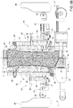
Figure 1 is a schematic front view, with parts removed for clarity, of a packaging assembly for forming a plurality of sealed packs according to the present invention; -
Figure 2 is a perspective view, with parts removed for clarity, of a portion of the packaging assembly ofFigure 1 ; -
Figure 3 is a larger-scale, exploded perspective view, with parts removed for clarity, of a cart of the packaging assembly ofFigure 1 ; -
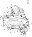
Figure 4 is a larger-scale, perspective sectioned view, with parts removed for clarity, of two mutually cooperating carts of the packaging assembly ofFigure 1 ; -
Figures 5a and5b are two larger-scale, schematic, partially-sectioned side views, with parts removed for clarity, of the two mutually cooperating carts ofFigure 4 in two different operating conditions; -
Figure 6 is a larger-scale, perspective view, with parts removed for clarity of a cart of a packaging assembly according to a second preferred embodiment of the present invention; -
Figure 7a is a perspective view of a package obtained by folding a pack formed and sealed by the packaging assembly according to the present invention; and -
Figure 7b is a side view of the package ofFigure 7a in which bottom flaps of the package have been detached from a bottom wall of the package and top flaps of the package have been detached from side walls of the package to better show that the package comprises a top sealing band that is not aligned with a bottom sealing band. - With reference to
Figure 1 , number 1 indicates as a whole a packaging assembly configured to form and seal a plurality ofpacks 3 containing a pourable product, preferably a pourable food product, starting from atube 2 of packaging material. - The packaging material has a multilayer structure (not shown), and comprises a layer of fibrous material, e.g. paper, covered on both sides with respective layers of heat-seal plastic material, e.g. polyethylene.
- In the case of
aseptic packs 3 for long-storage products, such as UHT milk, the packaging material also comprises a layer of gas-and-light barrier material, e.g. aluminum foil or ethylene vinyl alcohol (EVOH) film, which is superimposed on a layer of heat-seal plastic material, and is in turn covered with another layer of heat-seal plastic material, the latter forming the inner face of thepack 3 eventually contacting the pourable product. -
Tube 2 is formed in known manner by longitudinally folding and sealing a web (not shown) of packaging material.Tube 2 is then filled from above by a pipe (not shown) with the pourable product and is fed through packaging assembly 1 along a straight advancing direction A. In detail,tube 2 extends along a straight longitudinal, in particular vertical, axis X parallel to direction A. - It is also possible to identify two horizontal straight directions B, C orthogonal to one another and to direction A (
Figure 1 ). - Packaging assembly 1 comprises:
- a pair of
conveyors 4 arranged on respective lateral sides oftube 2, spaced apart with respect to one another along direction B, and configured to cooperate withtube 2; and - an
outlet conveyor 10, which is arranged belowconveyors 4 staggered with respect to axis X along direction B. - As shown in particular in
Figure 2 , eachconveyor 4 substantially comprises: - a box-shaped element 5, which includes an
endless track 6 defined by two rails arranged on opposite lateral sides of box-shaped element 5 spaced apart with respect to one another along direction C; and - a plurality of moving members, preferably
carts 7, each movably coupled to, and cyclically movable along, onerespective track 6. - In particular, each
cart 7 is configured to cyclically slide alongtrack 6 of therespective conveyor 4. In light of the above, a plurality ofcarts 7 slides, in use, along eachtrack 6. - To this end, each
cart 7 substantially comprises (Figures 2 and3 ) amovable body 14, which extends parallel to direction C, when coupled to therespective track 6, and which is provided with a plurality ofwheels 15 configured to movably engage therespective track 6. - In particular,
carts 7 of oneconveyor 4 are movable along therespective track 6 independently from one another and from thecarts 7 of theother conveyor 4. - For this purpose, each
cart 7 is provided with a magnetic portion, in particular apermanent magnet arrangement 11, and eachconveyor 4 comprises a plurality of electrically-supplied magnetic field generators, preferably electric coils 12, arranged within box-shaped element 5 in fixed positions. Coils 12 are configured to be magnetically coupled withpermanent magnet 11 of eachcart 7, so as to control the movement ofsuch cart 7 along therespective track 6. - In practice,
permanent magnets arrangements 11 and coils 12 -i.e. carts 7 and the respective track 6 - of eachconveyor 4 define a linear motor, which, in a known manner, is configured to independently control the movement ofcarts 7 along therespective track 6. - As a possible alternative not shown,
tracks 6 of the twoconveyors 4 may include one single rail. - With reference to
Figure 1 , the twotracks 6 define respective endless paths P, Q arranged on opposite sides of axis X oftube 2 with respect to direction B. More specifically, paths P, Q comprise: - respective operative branches P1, Q1, preferably rectilinear, between which
tube 2 is fed and along whichcarts 7 cooperate withtube 2; and - respective return branches P2, Q2, along which
carts 7 are detached fromtube 2. - According to this preferred embodiment shown, paths P, Q are substantially oval-shaped.
- In use, when sliding along the respective operative branch P1, Q1, each
cart 7 of oneconveyor 4 cooperates with acorresponding cart 7 of the other conveyor 4 - i.e.carts 7 mutually cooperates two by two - defining in this way a pair ofcarts 7 facing each other and cooperating with one another and withtube 2 while sliding along operative branches P1, Q1. - In particular, each pair of
carts 7 is configured to cooperate withtube 2 in order to cyclically form and seal onerespective pillow pack 3 at a time, and cut thepillow pack 3 to separate thepillow pack 3 fromtube 2, as shown inFigure 1 . - To this end, the
body 14 of eachcart 7 carries, at one of its sides, a formingunit 18 and a sealingunit 19 both configured to cooperate withtube 2 along the respective operative branches P1, Q1. - In particular, as better described below, forming
units 18 are configured to respectively cooperate withtube portions 13 oftube 2 to form at least corresponding pack portions, more in particularcorresponding packs 3. - For this purpose, each forming
unit 18 is carried by, preferably mounted on, therespective cart 7 in a movable manner and comprises a respective forming member, preferably a half-shell 20, presenting a C-shaped cross section and comprising amain wall 21 and a pair of lateral flaps 22. In the embodiment shown, flaps 22 are movably coupled towall 21. - In detail, flaps 22 project from opposite lateral edges of
wall 21, with respect to direction C when carts move along operative branches P1, Q1, and are hinged to such edges. - In use, the half-
shell 20 of each formingunit 18 is configured to sequentially and cyclically cooperate in contact withtube portions 13 so as to form at least pack portions ofrespective packs 3. - In greater detail, each half-
shell 20 is linearly movable transversally, in particular orthogonally, to direction A and axis X, towardstube 2, i.e. towards thetube portion 13 that half-shell 20 has to form. - In particular, each
cart 7 comprises amovable element 57 linearly movable transversally, in particular orthogonally, to direction A and axis X, which carries arespective half shell 20. - In particular,
movable element 57 is linearly movable along direction B. -
Sealing units 19 are configured to cooperate withtube 2 to sealtube portions 13 at predetermined, equally spaced, successive cross sections crosswise to direction A and located on a sealing plane S parallel to direction A and centered with respect totube 2, in order to sequentially form oppositetop sealing band 3a andbottom sealing band 3b in eachtube portion 13. In other words, sealing plane S axially intersectstube 2 and contains axis X. - Furthermore, sealing
units 19 are configured to cooperate withtube 2 to cutsuch packs 3 at the cross sections through thetop sealing band 3a andbottom sealing band 3b, so as to separatepacks 3 from one another. - On one
conveyor 4, each sealingunit 19 is mounted downstream of the corresponding formingunit 18 of therespective cart 7 along the respective path P, Q and comprises acounter-sealing device 17 and an extractable cutting element, for example a knife (not shown). - On the
other conveyor 4, each sealingunit 19 is mounted downstream of the corresponding formingunit 18 of therespective cart 7 along the respective path P, Q and comprises a sealingdevice 23 and a non-shown seat, adapted to receive the knife of thecorresponding sealing device 23 configured to cooperate with suchcounter-sealing device 17. - In the preferred embodiment shown, sealing
devices 23 are ultrasonic sealing devices. - According to an alternative embodiment not shown, sealing
devices 23 are inductive heating elements and the correspondingcounter-sealing devices 17 are made of elastomeric material, which provides the necessary mechanical support to griptube 2 to the required pressure during sealing operation. - As shown in
Figure 1 , when formingunits 18 and sealingunits 19 are advanced by therespective carts 7 of eachconveyor 4 along the respective operative branch P1, Q1, the respective half-shells 20, sealingdevices 23 andcounter-sealing devices 17 move back and forth along direction B between: - a closed position, or operative position, in which half-
shells 20, sealingdevices 23 andcounter-sealing devices 17 cooperate withrespective tube portions 13 to form, seal and cutrespective packs 3; and - an open position, or idle position, in which half-
shells 20, sealingdevices 23 andcounter-sealing devices 17 are detached fromtube 2 or from the formed packs 3. - In particular, when two half-
shells 20 of two respective formingunits 18 of a pair of cooperatingcarts 7 are both in the operative (closed) position, they define a substantially prismatic cavity and accordingly control the volume and shape of onerespective pack 3 being formed. - More specifically, when half-
shells 20 are in the operative (closed) position, theirwalls 21 are located on opposite sides ofrespective tube portions 13 and contactrespective tube portions 13. - In such a condition, flaps 22 of each half-
shell 20 rotate about the respective hinges from a position in which they diverge from therespective wall 21, to a position in which they are substantially orthogonal to thewall 21, face flaps 22 of the other half-shell 20 carried by the correspondingcart 7 of the same pair andcontact tube 2 to completely surround therespective tube portion 13 destined to form therespective pack 3. - When the
counter-sealing device 17 and sealingdevice 23 of a pair of cooperatingcarts 7 are in the operative (closed) position, they cooperate with one another to heat-seal tube 2, so as to formtop sealing band 3a andbottom sealing band 3b ofpacks 3, which are transversal to direction A and axis X, and lie on sealing plane S. - Then, the respective cutting element is extracted, so as to cut
packs 3 betweentop sealing band 3a (of one package) andbottom sealing band 3b (of an adjacent package) and separate formedpacks 3 from one another. - Conversely, when half-
shells 20,counter-sealing devices 17 and sealingdevices 23 are in the idle (open) position, they are detached fromtube 2. - According to the embodiment shown, the above-mentioned cyclic movement of half-shells 20 (
walls 21 and flaps 22),counter-sealing devices 17, sealingdevices 23 and cutting elements from their idle positions to their operative positions, is automatized (in a manner known per se and not described in detail) by cooperation between a cam assembly 24 (Figure 2 ), fixed with respect to theconveyors 4 andtracks 6, and a plurality of cam followers (partially shown inFigure 2 ) carried by eachcart 7. - In detail, according to this preferred embodiment, each one of the
walls 21, flaps 22, sealingdevices 23, cutting elements andcounter-sealing devices 17 carries at least one respective cam follower configured to cooperate in a sliding manner with a respective cam surface of thecam assembly 24. - In particular, flaps 22 of each forming
unit 18 carry arespective cam follower 25 configured to cooperate in a sliding manner with a corresponding cam surface of acam element 26 of thecam assembly 24. - More in detail,
cam followers 25 are configured to cooperate in a sliding manner with therespective cam elements 26 to be moved transversally to advancement direction A, whilecarts 7 move, in use, along operative branches P1, Q1. - In this specific embodiment, for each
cart 7,cam follower 25 is mechanically connected (coupled) toflaps 22 by means of a lever mechanism 27 (Figure 3 ) which is configured to drive the rotation offlaps 22 about their hinges in a known manner, due to interaction ofcam follower 25 withcam element 26. - Preferably, half-
shells 20,counter-sealing devices 17, sealingdevices 23 and cutting elements are pushed back towards their respective idle positions by springs (not shown), which act on the respective cam followers. -
Outlet conveyor 10 is configured to receive and conveypillow packs 3 towards a non-shown folding unit, in which packs 3 are folded into their final shapes, thereby obtaining respective packages 50 (one of which shown inFigure 7a ). - It is to be noted that
Figure 7b shows apillow pack 3 which does not correspond to any step of the forming cycle.Figure 7b merely shows apackage 50 with its flaps opened andtop sealing band 3a andbottom sealing band 3b raised (i.e. apackage 50 not fully folded). - In particular, as visible in
Figure 7b , pillow packs 3 comprise a substantially prismaticmain portion 51 having a longitudinal axis Y and being delimited at its bottom end by a flat horizontalbottom wall 52 and at its top end by a slantedtop wall 53. -
Top sealing band 3a andbottom sealing band 3b, formed by sealingunits 19 in the manner described above, protrude axially from slantedtop wall 53 andbottom wall 52, respectively. - More specifically, in packages 50 (
Figure 7a ) with a slanted top wall 53 - for example the Tetra Brik (registered trademark) Edge package -bottom sealing band 3b is coaxial to axis Y, whereastop sealing band 3a is off-centered with respect to axis Y. - In greater detail, when
top sealing band 3a protrudes vertically from slantedtop wall 53, as visible inFigure 7b , it is arranged offset with respect to axis Y by a distance 55 (measured orthogonally to axis Y). - Since, as described above, sealing
units 19 are configured to cooperate withtube 2 to sealtube portions 13 at cross sections located on sealing plane S, which is centered with respect totube 2, and sincetop sealing band 3a is arranged on slantedtop wall 53 ofpackage 50 offset with respect to axis Y so as to ensure the formation of slantedtop wall 53, a slight rotation oftube portions 13 occurs during the sealing operation. - Such a rotation is imparted during the sealing operation due to the particular pre-determined pattern of the crease lines (known per se and not shown) provided on the packaging material and necessary to determine the forming of
package 50 with slantedtop wall 53. - Hence, it is necessary for forming
units 18, in particular for half-shells 20, to sequentially follow and control (i.e. drive) the aforementioned rotation oftube portions 13 during sealing and formation ofpack 3. In fact, if not allowed to rotate,tube portions 13 would be damaged, due to the deformation caused by the folding imparted by the pattern of crease lines. - To this end, the
wall 21 of each half-shell 20 is tiltable with respect to direction A, to control a tilting of therespective tube portion 13 with respect to direction A. - In particular, each half-
shell 20 is tiltable with respect to the respectivemovable element 57. - In greater detail, half-
shell 20 comprises aback wall 56 connected tomovable element 57 and movably carrying wall 21 - and, through thiswall 21, flaps 22 - and linearly movable towards saidtube 2 along direction B. In particular, eachback wall 56 is arranged behind therespective wall 21 with respect to direction B. - Conveniently, each
wall 21 is tiltable with respect to therespective back wall 56, which does not tilt, but only moves linearly along direction B. - More specifically,
walls 21 of each pair of half-shells 20 are tiltable of angles α with respect to direction A and with respect to back walls 56 (Figure 5b ), in order to drive the tilting of the same angle α of thetube portions 13 they are cooperating with. - In light of the above,
walls 21 are both linearly movable along direction B, carried byback walls 56, and tiltable of the angle α with respect to direction A. - As visible in
Figure 5b , sinceflaps 22 are hinged towalls 21, also flaps 22 are tiltable with respect to therespective back walls 56. - Accordingly,
walls 21 are configured to be tilted whilecarts 7 are advancing parallel to direction A, in detail along operative branches P1, Q1 of endless paths P, Q, respectively. - In this way, the tilting of angle α of walls 21 - i.e. the tilting of angle α of tube portions 13 - ensures that half-
shells 20 follow and control the aforementioned rotation oftube portions 13, caused by the peculiar configuration of the crease lines thereon. - Furthermore, the above configuration ensures that the
top sealing band 3a of eachpackage 50 is formed offset of thedistance 55 with respect to the axis Y of thepackage 50, without compromising the structural integrity of thepackage 50. - In order to achieve the aforementioned tilting, packaging assembly 1 comprises actuator means configured to drive the tilting movement of each
wall 21, and therefore of eachtube portion 13. - According to this preferred embodiment, actuator means comprise
cam follower 25 andcam element 26. - For the sake of brevity, reference will be made in the following to a
single cart 7 configured to form and seal arespective tube portion 13. - However, all the features described hereinafter for
such cart 7 are applicable to allcarts 7 movably coupled totracks 6 ofconveyors 4. - In detail,
cart 7 comprises apusher mechanism 28 to whichcam follower 25 is fitted and which is configured to cooperate in contact with half-shell 20 to drive the tilting movement ofwall 21. - Accordingly,
wall 21 is movably coupled to backwall 56 of half-shell 20 by means of a hinge 29 (Figures 4 ,5a , and5b ) configured to allow a rotation ofwall 21 about direction C with respect to backwall 56. -
Pusher mechanism 28 comprises a pushingpin 30 coupled tocam follower 25, in particular integrally fixed tocam follower 25 so that to a transversal movement ofcam follower 25 along direction B and towards axis X, corresponds a transversal movement of pushingpin 30 along direction B and towards axis X. - Pushing
pin 30 is arranged behindback wall 56 andwall 21 of half-shell 20, with respect to direction B whencart 7 advances along operative branch P1 or Q1, and is configured to push ontowall 21 to drive the rotation ofwall 21 about itshinge 29, thereby controlling the tilting movement of angle α ofwall 21 and, therefore, of therespective tube portion 13. - Preferably,
back wall 56 is provided with a through hole (Figures 5a-5b ) through which pushingpin 30 passes, in use, before reachingwall 21. - In light of the above, the rotation of
flaps 22 and the tilting of wall 21 - and therefore of tube portion 13 - is driven by the same actuator means, i.e.cam follower 25 andcam element 26. - To this end,
cart 7 comprises a stoppingmember 31 configured to stop the movement of thelever mechanism 27 controlling the rotation offlaps 22, while allowing an extra-stroke ofpusher mechanism 28, and therefore ofpin 30, along direction B. - In detail, stopping
member 31 is configured to abut on an abutment surface ofcart 7 as soon asflaps 22 reach their final positions surroundingtube portion 13. - Thanks to this configuration of the actuator means, there is no need for dedicated actuator means configured to drive the tilting of
wall 21. - In light of the above,
wall 21 andtube portion 13 are movable between: - a first position, in which
pin 30 is detached fromwall 21,wall 21 is parallel to axis X and direction A, and axis Y oftube portion 13 is still parallel to axis X and sealing plane S (Figure 5a ); and - a second position, in which
pin 30 has pushedwall 21 so thatwall 21 is tilted of angle α,tube portion 13 is tilted of angle α and thetop sealing band 3a has been formed aligned with sealing plane S and axis X (Figure 5b ) . - Preferably, to ensure an automatic return of
wall 21 from the second position to the first position, elastic means are provided, for example aspring member 32 elastically couplingwall 21 to backwall 56. - More specifically,
spring member 32 is arranged on the opposite side ofwall 21 with respect to theside hinge 29 is arranged at, with respect to direction A. - Conveniently, for a given couple of half-
shells 20 cooperating with one another for forming apack 3, the positions ofhinges 29 andspring members 32 are inverted with respect to one another along direction A. In other words, a first half-shell 20 of the couple of half-shells has awall 21 that is hinged to an upper portion of the respective back wall 56 (with respect to direction A) and a second half-shell 20 of the couple of half-shells has awall 21 that is hinged to a lower portion of back wall 56 (with respect to direction A). - In this way, the transversal movement of
cam follower 25, driven by the shapedcam element 26, causes the tilting of angle α of wall 21 - i.e. the tilting of angle α of tube portion 13 - so that inpackage 50 thetop sealing band 3a is offset of thedistance 55 with respect to axis Y without compromising the structural integrity ofpackage 50, as visible inFigure 7a . - Conveniently, each forming
unit 18 is movable towards therespective sealing unit 19 of eachcart 7 along direction A, in a manner known and not described in detail. Such movement allows the forming of slantedtop wall 53 andbottom wall 54. - The operation of packaging assembly 1 is described hereafter starting from a condition in which a pair of cooperating
carts 7 slide along therespective tracks 6, following the respective paths P, Q and approaching the respective operative branches P1, Q1. - In this condition, each
cart 7 moves along the respective operative branch P1, Q1 and along direction A, and half-shell 20 (walls 21 and flaps 22), thecounter-sealing device 17, sealingdevice 23 and the cutting element are activated in sequence, by means of the interaction of the cam followers with the respective cam elements ofcam assembly 24. - At the same time,
tube 2 is filled from above with the pourable product. - After
flaps 22 have completed their rotation and cooperate in contact with therespective tube portion 13 to be formed, stoppingmembers 31 abut against the respective abutment surfaces and pins 30 start to move, due to the available extra-stroke. - As soon as
pins 30 contact therespective walls 21,walls 21 start to rotate about hinges 29, respectively, thereby tilting of angle α, so as to follow the rotation imparted totube portion 13 by the sealing operation. - After the forming, sealing and cutting of
tube 2 is completed, thereby obtaining apack 3, half-shells 20,counter-sealing device 17, sealingdevice 23 and the cutting element return in their idle positions. The formed and filledpack 3 is delivered tooutlet conveyor 10 and is conveyed to the above-mentioned folding unit to be folded in afinished package 50. -
Carts 7 then slide along the respective return branches P2, Q2 until they reach again the respective operative branches P1, Q1 to form anotherpack 3. - The entire operation is cyclically repeated for every
pack 3 to be formed, sealed and cut. The entire operation is also repeated for every pair ofcarts 7 which is present in packaging assembly 1. - Number 7' in
Figure 6 indicates as a whole a cart of a packaging assembly 1' according to a second embodiment of the present invention. - Packaging assembly 1' and cart 7' being similar to packaging assembly 1 and
carts 7 according to the first embodiment, the following description is limited to the differences between them, and using the same references, where possible, for identical or corresponding parts. - It is also stated that the features described hereinafter for cart 7' are applicable to all carts 7' that may be present in packaging assembly 1'.
- In particular, packaging assembly 1' differs from packaging assembly 1 in the type of actuator means used for driving the tilting movement of
tube portions 13. - In detail, packaging assembly 1' comprises dedicated actuator means exclusively configured to drive the tilting movement of
tube portions 13. - In greater detail, actuator means comprise a
dedicated cam follower 33 configured to cooperate in a sliding manner with the cam surface of adedicated cam element 34 of the cam assembly 24'. - More specifically, cart 7' comprises a forming unit 18' carrying a half-shell 20' having a main wall 21' which is coupled to
cam follower 33 by means of alever mechanism 35 configured to convert the transversal movement ofcam follower 33 in the tilting movement of angle α of wall 21'. - In detail, according to this preferred embodiment, the entire half-shell 20' is tiltable of angle α.
- In particular, half-shell 20' is tiltable with respect to the respective
movable element 57. - This particular configuration allows to have a dedicated control mechanism for the tilting of half-shells 20' and, therefore, of
tube portions 13 and permits to avoid the need for thepusher mechanism 28, hinges 29 andspring members 32. - The advantages of packaging assembly 1, 1' according to the present invention will be clear from the foregoing description.
- In particular, thanks to the tilting movement of
walls 21, 21' it is possible for the formingunits 18, 18' to follow and control the rotation of thetube portions 13 imparted thereto during the sealing operation due to the particular conformation of the crease lines in apackage 50 with a slantedtop wall 53, in the case in which thecarts 7, 7' are endlessly movable alongendless tracks 6, by means of a linear motor. - This further allows to obtain a
top sealing band 3a of eachpackage 50 offset with respect to axis Y ofsuch package 50, which provides for more space on slantedtop wall 53 to fit anopening device 54 thereon, without compromising the structural integrity ofpackage 50. - Moreover, the configuration of packaging assembly 1' and cart 7' allows to separate the actuation that controls the rotation of
flaps 22 from the one that controls the tilting of walls 21'; in practice, flaps 22 can be controlled even when the corresponding walls 21', and the half-shells 20' are tilted, impacts between components can be avoided and the tilting operation is more precise. - Clearly, changes may be made to packaging assembly 1, 1' as described herein without, however, departing from the scope of protection as defined in the accompanying claims.
Claims (16)
- A packaging assembly (1; 1') configured to form and seal a plurality of packs (3) containing a pourable product starting from a tube (2) of packaging material;
said packaging assembly (1; 1') comprising:- a pair of endless tracks (6) between which said tube (2) is fed along a straight advancement direction (A); and- a pair of movable members (7; 7'), each one of which movably coupled to, and cyclically movable along, one respective track (6);each movable member (7; 7') of said pair of movable members (7; 7') movably carrying one respective forming member (20; 20') linearly movable towards said tube (2), transversally to said advancement direction (A), to cyclically cooperate in contact with successive tube portions (13), so as to form at least corresponding pack portions of respective packs (3);
wherein each forming member (20; 20') comprises a movable portion (21; 21') which is tiltable with respect to said advancement direction (A), to sequentially control a tilting of said tube portions (13) with respect to said advancement direction (A). - The packaging assembly as claimed in claim 1, wherein each movable member (7; 7') comprises a movable element (57) linearly movable towards said tube (2) and supporting a respective movable portion (21); each movable portion (21) being tiltable with respect to the respective movable element (57).
- The packaging assembly as claimed in claim 1 or 2, wherein each movable member (7; 7') movably carries a respective sealing member (17, 23) configured to transversally seal said tube portions (13);
each forming member (20; 20') being movable with respect to the respective sealing member (17, 23) along said longitudinal direction (A). - The packaging assembly as claimed in any one of the foregoing claims, wherein said movable portion (21; 21') is tiltable of a given angle (α) with respect to said advancement direction (A).
- The packaging assembly as claimed in any one of the foregoing claims, and further comprising actuator means (25, 26; 33, 34) configured to drive the tilting movement of each movable portion (21; 21').
- The packaging assembly as claimed in claim 5, wherein said actuator means comprise, for each track (6), at least one cam surface (26; 34) fixed with respect to the track (6), and a cam follower (25; 33) carried by the respective forming member (20; 20') and configured to cooperate in a sliding manner with said cam surface (26; 34) .
- The packaging assembly (1) as claimed in claim 6, wherein each forming member (20) comprises forming elements (22) configured to form a respective portion of said packs (3); said cam follower (25) being mechanically connected to said forming elements (22); said actuator means (25, 26) being also configured to drive said forming elements (22).
- The packaging assembly (1) as claimed in claim 6 or 7, wherein said cam follower (25) is configured to cooperate with said cam surface (26) to be moved transversally to said advancement direction (A);
and wherein said movable member (7) comprises a pusher mechanism (28) to which said cam follower (25) is fitted and which is configured to cooperate in contact with the respective movable portion (21) to drive said tilting movement of said movable portion (21). - The packaging assembly (1) as claimed in claim 8, wherein said movable portion (21) is coupled to said forming member (20) at least by means of a hinge (29);
said pusher mechanism (28) comprising a pushing pin (30) integrally fixed to said cam follower (25) and configured to push onto the respective movable portion (21) to drive a rotation of the movable portion (21) about said hinge (29) to cause the tilting of said movable portion (21). - The packaging assembly (1') as claimed in claim 6, wherein said cam follower (33) is configured to cooperate with said cam surface (34) to be moved transversally to said advancement direction (A);
and wherein said cam follower (33) is coupled to the respective forming member (20') by means of a lever mechanism (35) configured to convert the transversal movement of said cam follower (33) in the tilting movement of said given angle (α) of said movable portion (21') ;
said actuator means (33, 34) being exclusively dedicated to drive said tilting of said movable portion (21'). - The packaging assembly as claimed in any one of the foregoing claims, wherein each movable member (7; 7') and the respective track (6) define a linear motor.
- The packaging assembly as claimed in any one of the foregoing claims, comprising a plurality of pairs of movable members (7; 7') cyclically movable along said tracks (6), respectively;
wherein the movable members (7; 7') which move, in use, along one track (6) of said pair of tracks (6) are independently movable with respect to one other and are configured to cooperate with corresponding movable members (7; 7') moving, in use, along the other track (6) of said pair of tracks (6). - The packaging assembly as claimed in any one of the foregoing claims, wherein said movable portion (21; 21') is tiltable so as to allow the forming of a package (50) with a slanted wall (53).
- A method for forming and sealing a plurality of packs (3) containing a pourable product starting from a tube (2) of packaging material, the method comprising the steps of:i) feeding said tube (2) between two endless tracks (6) along a straight advancement direction (A);ii) cyclically advancing a pair of forming members (20; 20') respectively along said tracks (6);iii) linearly moving said forming members (20; 20') towards said tube (2) to cyclically cooperate in contact with successive tube portions (13) so as to form at least corresponding pack portions of respective packs (3); andiv) tilting respective movable portions (21; 21') of said forming members (20; 20') with respect to said advancement direction (A), to sequentially control a tilting of said tube portions (13) with respect to said advancement direction (A)
- The method as claimed in claim 14, wherein said step iii) of linearly moving comprised the step of:
v) linearly moving movable elements (57) of a pair of movable members (7, 7'), each movable element (57) supporting a respective movable portion (21), each movable member (7; 7'), being movably coupled to, and cyclically movable along, one respective track (6);
and wherein said step iv) of tilting comprises the step of:
iv) tilting each movable portion (21; 21') with respect to the respective movable element (57). - The method as claimed in claim 14 or 15, and further comprising the steps of:vii) transversally sealing said tube portions (13) by means of a pair of sealing members (17, 23), each of said sealing members (17, 23) being carried by one respective movable member (7; 7'), each movable member (7; 7') being movably coupled to, and cyclically movable along, one respective track (6), each movable member (7; 7') movably carrying a respective forming member (20; 20');viii) moving each forming member (20; 20') with respect to the respective sealing member (17, 23) along said longitudinal direction (A).
Applications Claiming Priority (1)
| Application Number | Priority Date | Filing Date | Title |
|---|---|---|---|
| EP19183573 | 2019-07-01 |
Publications (2)
| Publication Number | Publication Date |
|---|---|
| EP3760548A1 true EP3760548A1 (en) | 2021-01-06 |
| EP3760548B1 EP3760548B1 (en) | 2024-08-14 |
Family
ID=67137808
Family Applications (1)
| Application Number | Title | Priority Date | Filing Date |
|---|---|---|---|
| EP20180266.7A Active EP3760548B1 (en) | 2019-07-01 | 2020-06-16 | A packaging assembly for forming and sealing a plurality of packs containing a pourable product and a method for forming and sealing a plurality of packs |
Country Status (5)
| Country | Link |
|---|---|
| US (1) | US20220363418A1 (en) |
| EP (1) | EP3760548B1 (en) |
| JP (1) | JP7839640B2 (en) |
| CN (1) | CN113853341A (en) |
| WO (1) | WO2021001144A1 (en) |
Cited By (4)
| Publication number | Priority date | Publication date | Assignee | Title |
|---|---|---|---|---|
| JP2023109306A (en) * | 2022-01-27 | 2023-08-08 | 四国化工機株式会社 | filling packaging machine |
| IT202300001578A1 (en) * | 2023-02-01 | 2024-08-01 | Tetra Laval Holdings & Finance | APPARATUS FOR FORMING PACKAGES FOR A PACKAGING MACHINE AND PACKAGING MACHINE FOR FORMING PACKAGES FILLED WITH A POURABLE PRODUCT |
| IT202300001572A1 (en) * | 2023-02-01 | 2024-08-01 | Tetra Laval Holdings & Finance | APPARATUS FOR FORMING PACKAGES FOR A PACKAGING MACHINE AND PACKAGING MACHINE FOR FORMING PACKAGES FILLED WITH A POURABLE PRODUCT |
| IT202300008166A1 (en) * | 2023-04-26 | 2024-10-26 | Tetra Laval Holdings & Finance | APPARATUS FOR FORMING PACKAGES FOR A PACKAGING MACHINE, PACKAGING MACHINE FOR FORMING PACKAGES FILLED WITH A POURABLE PRODUCT AND METHOD FOR FORMING PACKAGES |
Families Citing this family (1)
| Publication number | Priority date | Publication date | Assignee | Title |
|---|---|---|---|---|
| IT202300001899A1 (en) * | 2023-02-06 | 2024-08-06 | Tetra Laval Holdings & Finance | A MOBILE ELEMENT FOR A PACKAGE PRODUCTION SUPPORT SYSTEM, CORRESPONDING SYSTEM, FILLING MACHINE AND METHOD |
Citations (4)
| Publication number | Priority date | Publication date | Assignee | Title |
|---|---|---|---|---|
| EP0887264A1 (en) * | 1997-06-27 | 1998-12-30 | Tetra Laval Holdings & Finance SA | Packaging unit for continuously producing sealed packages, containing pourable food products, from a tube of packaging material |
| EP1832518A1 (en) * | 2006-03-07 | 2007-09-12 | Tetra Laval Holdings & Finance S.A. | Packing machine for producing sealed packages of pourable food products |
| EP3053835A1 (en) * | 2015-02-04 | 2016-08-10 | Tetra Laval Holdings & Finance S.A. | Forming assembly and method for forming a plurality of sealed packs for pourable food products starting from a tube of packaging material |
| EP3476751A1 (en) * | 2017-10-31 | 2019-05-01 | Tetra Laval Holdings & Finance S.A. | A packaging assembly for forming and sealing a plurality of packs containing a pourable food product |
Family Cites Families (20)
| Publication number | Priority date | Publication date | Assignee | Title |
|---|---|---|---|---|
| US4073121A (en) * | 1975-04-28 | 1978-02-14 | The Dow Chemical Company | Form, fill and seal industrial bag machine |
| CH620402A5 (en) * | 1977-11-09 | 1980-11-28 | Sig Schweiz Industrieges | |
| IT1233620B (en) * | 1989-06-06 | 1992-04-07 | Italpack Srl | FILLING AND PACKAGING MACHINE |
| ATE282551T1 (en) * | 1997-06-27 | 2004-12-15 | Tetra Laval Holdings & Finance | PACKAGING MACHINE FOR CONTINUOUSLY PRODUCING SEALED PACKAGINGS OF FLOWABLE FOODS FROM TUBULAR PACKAGING MATERIAL |
| ES2187746T3 (en) * | 1997-06-27 | 2003-06-16 | Tetra Laval Holdings & Finance | PACKING UNIT TO PRODUCE CONTINUOUSLY SEALED CONTAINERS, CONTAINING VERTIBLE FOOD PRODUCTS, FROM A PACKING MATERIAL PIPE. |
| EP0945349B1 (en) * | 1998-03-27 | 2004-01-02 | SIG Pack Systems AG | Device for transversal sealing and cutting of a thermoplastic packaging tube, especially for tubular bag packaging machines |
| TNSN00089A1 (en) * | 1999-04-26 | 2002-05-30 | Int Paper Co | MULTIPLE JAW SEALER |
| JP2002037206A (en) * | 2000-08-01 | 2002-02-06 | Ishida Co Ltd | Vertical bag making and packaging machine |
| PT1270182E (en) * | 2001-06-18 | 2008-08-04 | Tetra Laval Holdings & Finance | Induction sealing device for heat sealing packaging material |
| WO2003055749A1 (en) * | 2001-12-26 | 2003-07-10 | Tetra Laval Holdings & Finance S.A. | Filler |
| JP2003194662A (en) * | 2001-12-27 | 2003-07-09 | Nihon Tetra Pak Kk | Seal condition inspection device |
| SE0203701D0 (en) * | 2002-12-13 | 2002-12-13 | Tetra Laval Holdings & Finance | sealing device |
| SE529801C2 (en) * | 2006-03-31 | 2007-11-27 | Tetra Laval Holdings & Finance | Molding device, machine, molding process and process in the manufacture of packaging |
| EP2151390B1 (en) * | 2008-08-09 | 2015-09-30 | Tetra Laval Holdings & Finance S.A. | Packaging method and unit for producing sealed packages of a food product pourable into a tube of packaging material |
| EP2468634A1 (en) * | 2010-12-21 | 2012-06-27 | Tetra Laval Holdings & Finance S.A. | Forming member for forming sealed packages of pourable food products from a tube of packaging material |
| EP3219629B1 (en) * | 2016-03-17 | 2018-11-07 | Tetra Laval Holdings & Finance S.A. | A method and a machine for producing a sealed package |
| EP3219631B1 (en) * | 2016-03-18 | 2018-11-07 | Tetra Laval Holdings & Finance S.A. | A forming device and method for forming a pack into a finished package, a folding unit for forming sealed packages of pourable food products. |
| EP3238918B1 (en) * | 2016-04-28 | 2020-06-17 | Tetra Laval Holdings & Finance S.A. | An assembly for producing sealed packaging units |
| EP3241770B1 (en) * | 2016-05-06 | 2019-02-27 | Tetra Laval Holdings & Finance S.A. | A packaging unit for producing sealed packages containing a pourable food product from a tube of packaging material |
| EP3254980B1 (en) * | 2016-06-09 | 2018-12-19 | Tetra Laval Holdings & Finance S.A. | A packaging apparatus for forming sealed packages from a tube of packaging material |
-
2020
- 2020-06-16 WO PCT/EP2020/066616 patent/WO2021001144A1/en not_active Ceased
- 2020-06-16 CN CN202080035591.XA patent/CN113853341A/en active Pending
- 2020-06-16 US US17/623,289 patent/US20220363418A1/en not_active Abandoned
- 2020-06-16 EP EP20180266.7A patent/EP3760548B1/en active Active
- 2020-06-16 JP JP2021564740A patent/JP7839640B2/en active Active
Patent Citations (4)
| Publication number | Priority date | Publication date | Assignee | Title |
|---|---|---|---|---|
| EP0887264A1 (en) * | 1997-06-27 | 1998-12-30 | Tetra Laval Holdings & Finance SA | Packaging unit for continuously producing sealed packages, containing pourable food products, from a tube of packaging material |
| EP1832518A1 (en) * | 2006-03-07 | 2007-09-12 | Tetra Laval Holdings & Finance S.A. | Packing machine for producing sealed packages of pourable food products |
| EP3053835A1 (en) * | 2015-02-04 | 2016-08-10 | Tetra Laval Holdings & Finance S.A. | Forming assembly and method for forming a plurality of sealed packs for pourable food products starting from a tube of packaging material |
| EP3476751A1 (en) * | 2017-10-31 | 2019-05-01 | Tetra Laval Holdings & Finance S.A. | A packaging assembly for forming and sealing a plurality of packs containing a pourable food product |
Cited By (10)
| Publication number | Priority date | Publication date | Assignee | Title |
|---|---|---|---|---|
| JP2023109306A (en) * | 2022-01-27 | 2023-08-08 | 四国化工機株式会社 | filling packaging machine |
| IT202300001578A1 (en) * | 2023-02-01 | 2024-08-01 | Tetra Laval Holdings & Finance | APPARATUS FOR FORMING PACKAGES FOR A PACKAGING MACHINE AND PACKAGING MACHINE FOR FORMING PACKAGES FILLED WITH A POURABLE PRODUCT |
| IT202300001572A1 (en) * | 2023-02-01 | 2024-08-01 | Tetra Laval Holdings & Finance | APPARATUS FOR FORMING PACKAGES FOR A PACKAGING MACHINE AND PACKAGING MACHINE FOR FORMING PACKAGES FILLED WITH A POURABLE PRODUCT |
| EP4410523A1 (en) * | 2023-02-01 | 2024-08-07 | Tetra Laval Holdings & Finance S.A. | Package forming apparatus for a packaging machine and packaging machine for forming packages filled with a pourable product |
| EP4410522A1 (en) * | 2023-02-01 | 2024-08-07 | Tetra Laval Holdings & Finance S.A. | Package forming apparatus for a packaging machine and packaging machine for forming packages filled with a pourable product |
| WO2024160637A1 (en) * | 2023-02-01 | 2024-08-08 | Tetra Laval Holdings & Finance S.A. | Package forming apparatus for a packaging machine and packaging machine for forming packages filled with a pourable product |
| WO2024160636A1 (en) * | 2023-02-01 | 2024-08-08 | Tetra Laval Holdings & Finance S.A. | Package forming apparatus for a packaging machine and packaging machine for forming packages filled with a pourable product |
| IT202300008166A1 (en) * | 2023-04-26 | 2024-10-26 | Tetra Laval Holdings & Finance | APPARATUS FOR FORMING PACKAGES FOR A PACKAGING MACHINE, PACKAGING MACHINE FOR FORMING PACKAGES FILLED WITH A POURABLE PRODUCT AND METHOD FOR FORMING PACKAGES |
| WO2024223413A1 (en) * | 2023-04-26 | 2024-10-31 | Tetra Laval Holdings & Finance S.A. | Package forming apparatus for a packaging machine, packaging machine for forming packages filled with a pourable product and method for forming packages |
| EP4458689A1 (en) * | 2023-04-26 | 2024-11-06 | Tetra Laval Holdings & Finance S.A. | Package forming apparatus for a packaging machine, packaging machine for forming packages filled with a pourable product and method for forming packages |
Also Published As
| Publication number | Publication date |
|---|---|
| US20220363418A1 (en) | 2022-11-17 |
| JP2022537627A (en) | 2022-08-29 |
| EP3760548B1 (en) | 2024-08-14 |
| WO2021001144A1 (en) | 2021-01-07 |
| CN113853341A (en) | 2021-12-28 |
| JP7839640B2 (en) | 2026-04-02 |
Similar Documents
| Publication | Publication Date | Title |
|---|---|---|
| EP3760548B1 (en) | A packaging assembly for forming and sealing a plurality of packs containing a pourable product and a method for forming and sealing a plurality of packs | |
| EP3476751B1 (en) | A packaging assembly for forming and sealing a plurality of packs containing a pourable food product | |
| JP7137166B2 (en) | Packaging equipment for forming a sealed package from a tube of packaging material | |
| US9403611B2 (en) | Unit for sequencing and guiding items | |
| US9387943B2 (en) | Forming member for forming sealed packages of pourable food products from a tube of packaging material | |
| CN107206700B (en) | Assembly and method for forming a plurality of sealed packages for pourable food products starting from a tube of packaging material | |
| KR20150096790A (en) | Unit for the application of opening devices on sealed packages of food products | |
| KR101854097B1 (en) | Forming assembly and method for forming a plurality of sealed packs for pourable food products starting from a tube of packaging material | |
| EP4357253A1 (en) | Folding apparatus and packaging machine having a folding apparatus | |
| US20250361090A1 (en) | Conveying apparatus for a packaging machine, packaging machine having a conveying apparatus and a carrier for a conveying apparatus | |
| EP1832518B1 (en) | Packaging machine for producing sealed packages of pourable food products | |
| EP4357255A1 (en) | Folding apparatus and packaging machine having a folding apparatus | |
| EP4265533A1 (en) | Infeed conveyor for a folding apparatus, folding apparatus having an infeed conveyor and packaging machine having a folding apparatus | |
| EP3321192A1 (en) | Forming member for controlling the volume of packs of pourable food products formed from a tube of packaging material | |
| EP4357254A1 (en) | Folding apparatus and packaging machine having a folding apparatus | |
| EP4474299A1 (en) | Package forming apparatus and packaging machine for forming packages | |
| WO2024251615A1 (en) | Package forming apparatus and packaging machine for forming packages | |
| EP1826127A1 (en) | Folding unit for pourable food product packaging machines | |
| HK1117481B (en) | Unit for grouping packages along a path | |
| HK1117481A1 (en) | Unit for grouping packages along a path |
Legal Events
| Date | Code | Title | Description |
|---|---|---|---|
| PUAI | Public reference made under article 153(3) epc to a published international application that has entered the european phase |
Free format text: ORIGINAL CODE: 0009012 |
|
| STAA | Information on the status of an ep patent application or granted ep patent |
Free format text: STATUS: THE APPLICATION HAS BEEN PUBLISHED |
|
| AK | Designated contracting states |
Kind code of ref document: A1 Designated state(s): AL AT BE BG CH CY CZ DE DK EE ES FI FR GB GR HR HU IE IS IT LI LT LU LV MC MK MT NL NO PL PT RO RS SE SI SK SM TR |
|
| AX | Request for extension of the european patent |
Extension state: BA ME |
|
| STAA | Information on the status of an ep patent application or granted ep patent |
Free format text: STATUS: REQUEST FOR EXAMINATION WAS MADE |
|
| 17P | Request for examination filed |
Effective date: 20210706 |
|
| RBV | Designated contracting states (corrected) |
Designated state(s): AL AT BE BG CH CY CZ DE DK EE ES FI FR GB GR HR HU IE IS IT LI LT LU LV MC MK MT NL NO PL PT RO RS SE SI SK SM TR |
|
| STAA | Information on the status of an ep patent application or granted ep patent |
Free format text: STATUS: EXAMINATION IS IN PROGRESS |
|
| 17Q | First examination report despatched |
Effective date: 20211116 |
|
| GRAP | Despatch of communication of intention to grant a patent |
Free format text: ORIGINAL CODE: EPIDOSNIGR1 |
|
| STAA | Information on the status of an ep patent application or granted ep patent |
Free format text: STATUS: GRANT OF PATENT IS INTENDED |
|
| INTG | Intention to grant announced |
Effective date: 20240426 |
|
| GRAS | Grant fee paid |
Free format text: ORIGINAL CODE: EPIDOSNIGR3 |
|
| GRAA | (expected) grant |
Free format text: ORIGINAL CODE: 0009210 |
|
| STAA | Information on the status of an ep patent application or granted ep patent |
Free format text: STATUS: THE PATENT HAS BEEN GRANTED |
|
| P01 | Opt-out of the competence of the unified patent court (upc) registered |
Free format text: CASE NUMBER: APP_36782/2024 Effective date: 20240620 |
|
| AK | Designated contracting states |
Kind code of ref document: B1 Designated state(s): AL AT BE BG CH CY CZ DE DK EE ES FI FR GB GR HR HU IE IS IT LI LT LU LV MC MK MT NL NO PL PT RO RS SE SI SK SM TR |
|
| REG | Reference to a national code |
Ref country code: GB Ref legal event code: FG4D |
|
| REG | Reference to a national code |
Ref country code: CH Ref legal event code: EP |
|
| REG | Reference to a national code |
Ref country code: DE Ref legal event code: R096 Ref document number: 602020035634 Country of ref document: DE |
|
| REG | Reference to a national code |
Ref country code: IE Ref legal event code: FG4D |
|
| REG | Reference to a national code |
Ref country code: LT Ref legal event code: MG9D |
|
| REG | Reference to a national code |
Ref country code: NL Ref legal event code: MP Effective date: 20240814 |
|
| PG25 | Lapsed in a contracting state [announced via postgrant information from national office to epo] |
Ref country code: NO Free format text: LAPSE BECAUSE OF FAILURE TO SUBMIT A TRANSLATION OF THE DESCRIPTION OR TO PAY THE FEE WITHIN THE PRESCRIBED TIME-LIMIT Effective date: 20241114 |
|
| REG | Reference to a national code |
Ref country code: AT Ref legal event code: MK05 Ref document number: 1713111 Country of ref document: AT Kind code of ref document: T Effective date: 20240814 |
|
| PG25 | Lapsed in a contracting state [announced via postgrant information from national office to epo] |
Ref country code: FI Free format text: LAPSE BECAUSE OF FAILURE TO SUBMIT A TRANSLATION OF THE DESCRIPTION OR TO PAY THE FEE WITHIN THE PRESCRIBED TIME-LIMIT Effective date: 20240814 Ref country code: NL Free format text: LAPSE BECAUSE OF FAILURE TO SUBMIT A TRANSLATION OF THE DESCRIPTION OR TO PAY THE FEE WITHIN THE PRESCRIBED TIME-LIMIT Effective date: 20240814 Ref country code: PT Free format text: LAPSE BECAUSE OF FAILURE TO SUBMIT A TRANSLATION OF THE DESCRIPTION OR TO PAY THE FEE WITHIN THE PRESCRIBED TIME-LIMIT Effective date: 20241216 Ref country code: GR Free format text: LAPSE BECAUSE OF FAILURE TO SUBMIT A TRANSLATION OF THE DESCRIPTION OR TO PAY THE FEE WITHIN THE PRESCRIBED TIME-LIMIT Effective date: 20241115 Ref country code: PL Free format text: LAPSE BECAUSE OF FAILURE TO SUBMIT A TRANSLATION OF THE DESCRIPTION OR TO PAY THE FEE WITHIN THE PRESCRIBED TIME-LIMIT Effective date: 20240814 |
|
| PG25 | Lapsed in a contracting state [announced via postgrant information from national office to epo] |
Ref country code: BG Free format text: LAPSE BECAUSE OF FAILURE TO SUBMIT A TRANSLATION OF THE DESCRIPTION OR TO PAY THE FEE WITHIN THE PRESCRIBED TIME-LIMIT Effective date: 20240814 |
|
| PG25 | Lapsed in a contracting state [announced via postgrant information from national office to epo] |
Ref country code: LV Free format text: LAPSE BECAUSE OF FAILURE TO SUBMIT A TRANSLATION OF THE DESCRIPTION OR TO PAY THE FEE WITHIN THE PRESCRIBED TIME-LIMIT Effective date: 20240814 |
|
| PG25 | Lapsed in a contracting state [announced via postgrant information from national office to epo] |
Ref country code: AT Free format text: LAPSE BECAUSE OF FAILURE TO SUBMIT A TRANSLATION OF THE DESCRIPTION OR TO PAY THE FEE WITHIN THE PRESCRIBED TIME-LIMIT Effective date: 20240814 Ref country code: IS Free format text: LAPSE BECAUSE OF FAILURE TO SUBMIT A TRANSLATION OF THE DESCRIPTION OR TO PAY THE FEE WITHIN THE PRESCRIBED TIME-LIMIT Effective date: 20241214 |
|
| PG25 | Lapsed in a contracting state [announced via postgrant information from national office to epo] |
Ref country code: HR Free format text: LAPSE BECAUSE OF FAILURE TO SUBMIT A TRANSLATION OF THE DESCRIPTION OR TO PAY THE FEE WITHIN THE PRESCRIBED TIME-LIMIT Effective date: 20240814 |
|
| PG25 | Lapsed in a contracting state [announced via postgrant information from national office to epo] |
Ref country code: RS Free format text: LAPSE BECAUSE OF FAILURE TO SUBMIT A TRANSLATION OF THE DESCRIPTION OR TO PAY THE FEE WITHIN THE PRESCRIBED TIME-LIMIT Effective date: 20241114 Ref country code: ES Free format text: LAPSE BECAUSE OF FAILURE TO SUBMIT A TRANSLATION OF THE DESCRIPTION OR TO PAY THE FEE WITHIN THE PRESCRIBED TIME-LIMIT Effective date: 20240814 |
|
| PG25 | Lapsed in a contracting state [announced via postgrant information from national office to epo] |
Ref country code: RS Free format text: LAPSE BECAUSE OF FAILURE TO SUBMIT A TRANSLATION OF THE DESCRIPTION OR TO PAY THE FEE WITHIN THE PRESCRIBED TIME-LIMIT Effective date: 20241114 Ref country code: PT Free format text: LAPSE BECAUSE OF FAILURE TO SUBMIT A TRANSLATION OF THE DESCRIPTION OR TO PAY THE FEE WITHIN THE PRESCRIBED TIME-LIMIT Effective date: 20241216 Ref country code: PL Free format text: LAPSE BECAUSE OF FAILURE TO SUBMIT A TRANSLATION OF THE DESCRIPTION OR TO PAY THE FEE WITHIN THE PRESCRIBED TIME-LIMIT Effective date: 20240814 Ref country code: NO Free format text: LAPSE BECAUSE OF FAILURE TO SUBMIT A TRANSLATION OF THE DESCRIPTION OR TO PAY THE FEE WITHIN THE PRESCRIBED TIME-LIMIT Effective date: 20241114 Ref country code: NL Free format text: LAPSE BECAUSE OF FAILURE TO SUBMIT A TRANSLATION OF THE DESCRIPTION OR TO PAY THE FEE WITHIN THE PRESCRIBED TIME-LIMIT Effective date: 20240814 Ref country code: LV Free format text: LAPSE BECAUSE OF FAILURE TO SUBMIT A TRANSLATION OF THE DESCRIPTION OR TO PAY THE FEE WITHIN THE PRESCRIBED TIME-LIMIT Effective date: 20240814 Ref country code: IS Free format text: LAPSE BECAUSE OF FAILURE TO SUBMIT A TRANSLATION OF THE DESCRIPTION OR TO PAY THE FEE WITHIN THE PRESCRIBED TIME-LIMIT Effective date: 20241214 Ref country code: HR Free format text: LAPSE BECAUSE OF FAILURE TO SUBMIT A TRANSLATION OF THE DESCRIPTION OR TO PAY THE FEE WITHIN THE PRESCRIBED TIME-LIMIT Effective date: 20240814 Ref country code: GR Free format text: LAPSE BECAUSE OF FAILURE TO SUBMIT A TRANSLATION OF THE DESCRIPTION OR TO PAY THE FEE WITHIN THE PRESCRIBED TIME-LIMIT Effective date: 20241115 Ref country code: FI Free format text: LAPSE BECAUSE OF FAILURE TO SUBMIT A TRANSLATION OF THE DESCRIPTION OR TO PAY THE FEE WITHIN THE PRESCRIBED TIME-LIMIT Effective date: 20240814 Ref country code: ES Free format text: LAPSE BECAUSE OF FAILURE TO SUBMIT A TRANSLATION OF THE DESCRIPTION OR TO PAY THE FEE WITHIN THE PRESCRIBED TIME-LIMIT Effective date: 20240814 Ref country code: BG Free format text: LAPSE BECAUSE OF FAILURE TO SUBMIT A TRANSLATION OF THE DESCRIPTION OR TO PAY THE FEE WITHIN THE PRESCRIBED TIME-LIMIT Effective date: 20240814 Ref country code: AT Free format text: LAPSE BECAUSE OF FAILURE TO SUBMIT A TRANSLATION OF THE DESCRIPTION OR TO PAY THE FEE WITHIN THE PRESCRIBED TIME-LIMIT Effective date: 20240814 |
|
| PG25 | Lapsed in a contracting state [announced via postgrant information from national office to epo] |
Ref country code: RO Free format text: LAPSE BECAUSE OF FAILURE TO SUBMIT A TRANSLATION OF THE DESCRIPTION OR TO PAY THE FEE WITHIN THE PRESCRIBED TIME-LIMIT Effective date: 20240814 Ref country code: DK Free format text: LAPSE BECAUSE OF FAILURE TO SUBMIT A TRANSLATION OF THE DESCRIPTION OR TO PAY THE FEE WITHIN THE PRESCRIBED TIME-LIMIT Effective date: 20240814 Ref country code: SM Free format text: LAPSE BECAUSE OF FAILURE TO SUBMIT A TRANSLATION OF THE DESCRIPTION OR TO PAY THE FEE WITHIN THE PRESCRIBED TIME-LIMIT Effective date: 20240814 |
|
| PG25 | Lapsed in a contracting state [announced via postgrant information from national office to epo] |
Ref country code: EE Free format text: LAPSE BECAUSE OF FAILURE TO SUBMIT A TRANSLATION OF THE DESCRIPTION OR TO PAY THE FEE WITHIN THE PRESCRIBED TIME-LIMIT Effective date: 20240814 |
|
| PG25 | Lapsed in a contracting state [announced via postgrant information from national office to epo] |
Ref country code: CZ Free format text: LAPSE BECAUSE OF FAILURE TO SUBMIT A TRANSLATION OF THE DESCRIPTION OR TO PAY THE FEE WITHIN THE PRESCRIBED TIME-LIMIT Effective date: 20240814 |
|
| PG25 | Lapsed in a contracting state [announced via postgrant information from national office to epo] |
Ref country code: SK Free format text: LAPSE BECAUSE OF FAILURE TO SUBMIT A TRANSLATION OF THE DESCRIPTION OR TO PAY THE FEE WITHIN THE PRESCRIBED TIME-LIMIT Effective date: 20240814 |
|
| REG | Reference to a national code |
Ref country code: DE Ref legal event code: R097 Ref document number: 602020035634 Country of ref document: DE |
|
| PLBE | No opposition filed within time limit |
Free format text: ORIGINAL CODE: 0009261 |
|
| STAA | Information on the status of an ep patent application or granted ep patent |
Free format text: STATUS: NO OPPOSITION FILED WITHIN TIME LIMIT |
|
| PGFP | Annual fee paid to national office [announced via postgrant information from national office to epo] |
Ref country code: DE Payment date: 20250626 Year of fee payment: 6 |
|
| 26N | No opposition filed |
Effective date: 20250515 |
|
| PG25 | Lapsed in a contracting state [announced via postgrant information from national office to epo] |
Ref country code: SE Free format text: LAPSE BECAUSE OF FAILURE TO SUBMIT A TRANSLATION OF THE DESCRIPTION OR TO PAY THE FEE WITHIN THE PRESCRIBED TIME-LIMIT Effective date: 20240814 |
|
| PGFP | Annual fee paid to national office [announced via postgrant information from national office to epo] |
Ref country code: IT Payment date: 20250623 Year of fee payment: 6 |
|
| REG | Reference to a national code |
Ref country code: CH Ref legal event code: H13 Free format text: ST27 STATUS EVENT CODE: U-0-0-H10-H13 (AS PROVIDED BY THE NATIONAL OFFICE) Effective date: 20260127 |
|
| PG25 | Lapsed in a contracting state [announced via postgrant information from national office to epo] |
Ref country code: MC Free format text: LAPSE BECAUSE OF FAILURE TO SUBMIT A TRANSLATION OF THE DESCRIPTION OR TO PAY THE FEE WITHIN THE PRESCRIBED TIME-LIMIT Effective date: 20240814 |
|
| PG25 | Lapsed in a contracting state [announced via postgrant information from national office to epo] |
Ref country code: LU Free format text: LAPSE BECAUSE OF NON-PAYMENT OF DUE FEES Effective date: 20250616 |
|
| GBPC | Gb: european patent ceased through non-payment of renewal fee |
Effective date: 20250616 |
|
| REG | Reference to a national code |
Ref country code: BE Ref legal event code: MM Effective date: 20250630 |
|
| PG25 | Lapsed in a contracting state [announced via postgrant information from national office to epo] |
Ref country code: GB Free format text: LAPSE BECAUSE OF NON-PAYMENT OF DUE FEES Effective date: 20250616 |
|
| PG25 | Lapsed in a contracting state [announced via postgrant information from national office to epo] |
Ref country code: IE Free format text: LAPSE BECAUSE OF NON-PAYMENT OF DUE FEES Effective date: 20250616 |
|
| PG25 | Lapsed in a contracting state [announced via postgrant information from national office to epo] |
Ref country code: BE Free format text: LAPSE BECAUSE OF NON-PAYMENT OF DUE FEES Effective date: 20250630 |
|
| PG25 | Lapsed in a contracting state [announced via postgrant information from national office to epo] |
Ref country code: FR Free format text: LAPSE BECAUSE OF NON-PAYMENT OF DUE FEES Effective date: 20250630 |
|
| PG25 | Lapsed in a contracting state [announced via postgrant information from national office to epo] |
Ref country code: CH Free format text: LAPSE BECAUSE OF NON-PAYMENT OF DUE FEES Effective date: 20250630 |