EP3760464B1 - Batteriespeicherrack und batteriebetriebsplattform - Google Patents
Batteriespeicherrack und batteriebetriebsplattform Download PDFInfo
- Publication number
- EP3760464B1 EP3760464B1 EP18907808.2A EP18907808A EP3760464B1 EP 3760464 B1 EP3760464 B1 EP 3760464B1 EP 18907808 A EP18907808 A EP 18907808A EP 3760464 B1 EP3760464 B1 EP 3760464B1
- Authority
- EP
- European Patent Office
- Prior art keywords
- connector
- battery
- bracket
- fluid
- storage rack
- Prior art date
- Legal status (The legal status is an assumption and is not a legal conclusion. Google has not performed a legal analysis and makes no representation as to the accuracy of the status listed.)
- Active
Links
Images

Classifications
-
- B—PERFORMING OPERATIONS; TRANSPORTING
- B60—VEHICLES IN GENERAL
- B60K—ARRANGEMENT OR MOUNTING OF PROPULSION UNITS OR OF TRANSMISSIONS IN VEHICLES; ARRANGEMENT OR MOUNTING OF PLURAL DIVERSE PRIME-MOVERS IN VEHICLES; AUXILIARY DRIVES FOR VEHICLES; INSTRUMENTATION OR DASHBOARDS FOR VEHICLES; ARRANGEMENTS IN CONNECTION WITH COOLING, AIR INTAKE, GAS EXHAUST OR FUEL SUPPLY OF PROPULSION UNITS IN VEHICLES
- B60K1/00—Arrangement or mounting of electrical propulsion units
- B60K1/04—Arrangement or mounting of electrical propulsion units of the electric storage means for propulsion
-
- B—PERFORMING OPERATIONS; TRANSPORTING
- B60—VEHICLES IN GENERAL
- B60K—ARRANGEMENT OR MOUNTING OF PROPULSION UNITS OR OF TRANSMISSIONS IN VEHICLES; ARRANGEMENT OR MOUNTING OF PLURAL DIVERSE PRIME-MOVERS IN VEHICLES; AUXILIARY DRIVES FOR VEHICLES; INSTRUMENTATION OR DASHBOARDS FOR VEHICLES; ARRANGEMENTS IN CONNECTION WITH COOLING, AIR INTAKE, GAS EXHAUST OR FUEL SUPPLY OF PROPULSION UNITS IN VEHICLES
- B60K11/00—Arrangement in connection with cooling of propulsion units
- B60K11/02—Arrangement in connection with cooling of propulsion units with liquid cooling
-
- H—ELECTRICITY
- H01—ELECTRIC ELEMENTS
- H01M—PROCESSES OR MEANS, e.g. BATTERIES, FOR THE DIRECT CONVERSION OF CHEMICAL ENERGY INTO ELECTRICAL ENERGY
- H01M10/00—Secondary cells; Manufacture thereof
- H01M10/60—Heating or cooling; Temperature control
- H01M10/61—Types of temperature control
- H01M10/613—Cooling or keeping cold
-
- H—ELECTRICITY
- H01—ELECTRIC ELEMENTS
- H01M—PROCESSES OR MEANS, e.g. BATTERIES, FOR THE DIRECT CONVERSION OF CHEMICAL ENERGY INTO ELECTRICAL ENERGY
- H01M10/00—Secondary cells; Manufacture thereof
- H01M10/60—Heating or cooling; Temperature control
- H01M10/65—Means for temperature control structurally associated with the cells
- H01M10/656—Means for temperature control structurally associated with the cells characterised by the type of heat-exchange fluid
- H01M10/6567—Liquids
- H01M10/6568—Liquids characterised by flow circuits, e.g. loops, located externally to the cells or cell casings
-
- H—ELECTRICITY
- H01—ELECTRIC ELEMENTS
- H01M—PROCESSES OR MEANS, e.g. BATTERIES, FOR THE DIRECT CONVERSION OF CHEMICAL ENERGY INTO ELECTRICAL ENERGY
- H01M50/00—Constructional details or processes of manufacture of the non-active parts of electrochemical cells other than fuel cells, e.g. hybrid cells
- H01M50/20—Mountings; Secondary casings or frames; Racks, modules or packs; Suspension devices; Shock absorbers; Transport or carrying devices; Holders
- H01M50/249—Mountings; Secondary casings or frames; Racks, modules or packs; Suspension devices; Shock absorbers; Transport or carrying devices; Holders specially adapted for aircraft or vehicles, e.g. cars or trains
-
- B—PERFORMING OPERATIONS; TRANSPORTING
- B60—VEHICLES IN GENERAL
- B60K—ARRANGEMENT OR MOUNTING OF PROPULSION UNITS OR OF TRANSMISSIONS IN VEHICLES; ARRANGEMENT OR MOUNTING OF PLURAL DIVERSE PRIME-MOVERS IN VEHICLES; AUXILIARY DRIVES FOR VEHICLES; INSTRUMENTATION OR DASHBOARDS FOR VEHICLES; ARRANGEMENTS IN CONNECTION WITH COOLING, AIR INTAKE, GAS EXHAUST OR FUEL SUPPLY OF PROPULSION UNITS IN VEHICLES
- B60K1/00—Arrangement or mounting of electrical propulsion units
- B60K2001/003—Arrangement or mounting of electrical propulsion units with means for cooling the electrical propulsion units
- B60K2001/005—Arrangement or mounting of electrical propulsion units with means for cooling the electrical propulsion units the electric storage means
-
- H—ELECTRICITY
- H01—ELECTRIC ELEMENTS
- H01M—PROCESSES OR MEANS, e.g. BATTERIES, FOR THE DIRECT CONVERSION OF CHEMICAL ENERGY INTO ELECTRICAL ENERGY
- H01M10/00—Secondary cells; Manufacture thereof
- H01M10/60—Heating or cooling; Temperature control
- H01M10/65—Means for temperature control structurally associated with the cells
- H01M10/656—Means for temperature control structurally associated with the cells characterised by the type of heat-exchange fluid
- H01M10/6561—Gases
-
- H—ELECTRICITY
- H01—ELECTRIC ELEMENTS
- H01M—PROCESSES OR MEANS, e.g. BATTERIES, FOR THE DIRECT CONVERSION OF CHEMICAL ENERGY INTO ELECTRICAL ENERGY
- H01M2220/00—Batteries for particular applications
- H01M2220/20—Batteries in motive systems, e.g. vehicle, ship, plane
-
- Y—GENERAL TAGGING OF NEW TECHNOLOGICAL DEVELOPMENTS; GENERAL TAGGING OF CROSS-SECTIONAL TECHNOLOGIES SPANNING OVER SEVERAL SECTIONS OF THE IPC; TECHNICAL SUBJECTS COVERED BY FORMER USPC CROSS-REFERENCE ART COLLECTIONS [XRACs] AND DIGESTS
- Y02—TECHNOLOGIES OR APPLICATIONS FOR MITIGATION OR ADAPTATION AGAINST CLIMATE CHANGE
- Y02E—REDUCTION OF GREENHOUSE GAS [GHG] EMISSIONS, RELATED TO ENERGY GENERATION, TRANSMISSION OR DISTRIBUTION
- Y02E60/00—Enabling technologies; Technologies with a potential or indirect contribution to GHG emissions mitigation
- Y02E60/10—Energy storage using batteries
Definitions
- the invention relates to the technical field of vehicles, and in particular to a battery storage rack and a battery operation platform.
- the battery power supplement time will be an important indicator, if the user experience of battery charging for vehicles is to overmatch that of the fuelling for traditional vehicles.
- Battery swapping is a way to achieve quick power supplement.
- battery swapping will still be the most possible way to alleviate users' anxiety about available driving range, and to achieve that the vehicle battery power supplement time can be comparable to or even overmatch that of the fuelling for traditional vehicles.
- the fluid inlet and the fluid outlet are arranged adjacently to a respective plate-shaped frame component remotely from the heat sink, and at least one of the fluid connections has at least one first connection unit, which is arranged adjacently to the respective plate-shaped frame component remotely from the heat sink and which forms the fluid inlet or the fluid outlet, and at least one fluid line which is communicatively connected to the first connection unit.
- the battery module has at least one clamping device.
- the fluid connection comprising the first connection unit has at least one second connection unit which is communicatively connected to the cooling channel system, and the two connection units can be clamped against each other by means of the clamping device.
- the second connection unit is arranged adjacently to the respective plate-shaped frame component remotely from the heat sink and is connected to the plate-shaped heat sink at the end face, and the fluid line is connected to at least one of the two connection units via at least one seal.
- the fluid cooling device is provided for cooling a battery located in a storage space of a battery storage rack, so as to reduce the substrate temperature of the battery, and to effectively control and reduce the heat accumulated inside the battery storage rack.
- a battery to be charged and supplemented with energy is placed in a storage space of a battery storage rack 16.
- Such a battery may be a used battery that is unloaded from a vehicle by a battery swap operation device and then moved into the storage space of the battery storage rack 16, and is recharged such that the battery is supplemented with power and restored, so that the battery can then be moved out of the storage space of the battery storage rack 16 when needed and loaded into a vehicle with a battery needing to be swapped.
- the above-mentioned vehicle includes but is not limited to a battery electric vehicle, a hybrid battery vehicle, etc.
- the second bracket 2 and the first bracket 1 are arranged adjacent to each other, and the fluid cooling terminal unit 3 is mounted on the second bracket 2, such that the second bracket 2 can be driven by the driving unit 4 to move relative to the first bracket 1, so as to cause the fluid cooling device to engage with a corresponding connector of the battery to be charged to transfer fluid (for example, various suitable liquids or gases such as water) to the corresponding connector to achieve the cooling and temperature-reducing effect, or to cause the fluid cooling device to disengage from the corresponding connector, or an inlet or an outlet of the battery if there is no need to continue cooling the battery (such as the battery has been fully charged).
- fluid for example, various suitable liquids or gases such as water
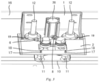
- the fluid cooling terminal unit 3 is provided with a first connector 6, a second connector 7, a third connector 8, and a fourth connector 9, wherein the first connector 6 and the second connector 7 remain in fluid communication with each other, and the third connector 8 and the fourth connector 9 remain in fluid communication with each other; and the first connector 6 may be connected to an output port 13 of a pipeline 15 for supplying a cooling fluid via a connecting component such as a flexible pipe to form a fluid flow path, and the third connector 8 may be similarly connected to an input port 14 of the pipeline 15 via a connecting component such as a flexible pipe.
- the second connector 7 and the fourth connector 9 are respectively configured to match a fluid inlet and a fluid outlet provided on the rechargeable battery respectively, such that a communication pipeline can be detachably formed. That is to say, under the driving action of the driving unit 4, the second connector 7 may be engaged with the fluid inlet on the rechargeable battery to communicate with each other, and the fourth connector 9 may be engaged with the fluid outlet on the rechargeable battery to communicate with each other, so that a fluid circulation circuit in which fluid sequentially flows from the output port 13 of the pipeline 15 through the first connector 6, the second connector 7, and the fluid inlet of the battery to an internal flow pipeline of the battery, and then flows out from the fluid outlet of the battery back to the pipeline 15 through the fourth connector 9, the third connector 8 and the input port 14 is formed.
- a fluid circulation circuit in which fluid sequentially flows from the output port 13 of the pipeline 15 through the first connector 6, the second connector 7, and the fluid inlet of the battery to an internal flow pipeline of the battery, and then flows out from the fluid outlet of the battery back to the pipeline 15 through the fourth
- the first connector 6 and/or the third connector 8 may be configured to rotate within a certain angle range in a circumferential direction (this can be pre-designed according to specific application requirements). Providing such a degree of freedom of spatial rotation is not only convenient for practical operation, but also very beneficial to protect components such as the connectors, and connecting pipes, so that the components are durable and are not likely to be damaged to cause outward fluid leakage, which can improve the safety and reliability of the system.
- a perspective structure of the fluid cooling terminal unit 3 of this embodiment is schematically and generally shown in Fig. 2 .
- the fluid cooling terminal unit 3 is optionally configured to comprise two parts, namely, a first part 5 connected to the second bracket 2 and a second part 10 connected to the first part and therefore the second bracket 2.
- the reason for adopting this structural arrangement is that the second part 10 may be further preferably configured to have such degrees of freedom that not only can the second part 10 float on a horizontal plane relative to the first part 5, but can also perform a twisting movement, so that the complexity and manufacturing and maintenance costs of the device itself can be greatly reduced.
- the above-mentioned degrees of freedom of spatial movements can be achieved by arranging some elastic components such as springs on the second part 10 of the fluid cooling terminal unit 3.
- some elastic components such as springs
- four elastic components 11 may be optionally arranged on the second part 10, that is, opposite ends of the second part 10 are each provided with two elastic components 11, and the first part 5 is configured to have a connecting rod member mounted on the top of each elastic component 11, these connecting rod members passing through mounting holes 17 in the second bracket 2 and being screwed to the second bracket 2 with connecting members 18.
- the second part 10 of the fluid cooling terminal unit 3 can be elastically supported by the elastic forces provided by these elastic components 11.
- the second part 10 can be floated on the horizontal plane relative to the first part 5 and can be twisted, so that a self-return function is provided to realize a safe and reliable engagement or disengagement operation between the second connector 7 and the fourth connector 9 and the fluid inlet and the fluid outlet of the battery, that is, an insertion/withdrawal operation.
- a battery storage rack having one or more storage spaces for storing batteries.
- the fluid cooling device designed and provided according to the invention is provided in the storage space of the a battery storage rack, so as to give full play to the obvious technical advantages as described above provided by the solution of the invention.
- a battery operation platform there is also provided a battery operation platform.
- One or more battery storage racks designed and provided above according to the invention may be provided on the battery operation platform, such that such battery storage racks are provided to store batteries and charge and supplement same with energy, and the fluid cooling device designed and provided by the invention can be also used to safely and reliably cool these batteries and reduce the temperature thereof.
- the operations that can be achieved by the battery operation platform include, but are not limited to, battery swap, charging, and monitoring of battery information (such as state of charge, health level, number of uses, etc. of a battery), and after completing the charging and energy supplement, the vehicle battery can be loaded into various types of new energy vehicles such as battery electric vehicles and hybrid electric vehicles, and put into use.
Landscapes
- Engineering & Computer Science (AREA)
- Chemical & Material Sciences (AREA)
- General Chemical & Material Sciences (AREA)
- Chemical Kinetics & Catalysis (AREA)
- Electrochemistry (AREA)
- Manufacturing & Machinery (AREA)
- Combustion & Propulsion (AREA)
- Transportation (AREA)
- Mechanical Engineering (AREA)
- Aviation & Aerospace Engineering (AREA)
- Secondary Cells (AREA)
- Battery Mounting, Suspending (AREA)
- Electric Propulsion And Braking For Vehicles (AREA)
Claims (11)
- Batteriespeicherrack (16) mit mindestens einem Speicherplatz, einer in dem Speicherplatz angeordneten Batterie, wobei der Speicherplatz mit einer Flüssigkeitskühlvorrichtung zum Kühlen der Batterie versehen ist, wobei die Flüssigkeitskühlvorrichtung Folgendes aufweist:eine erste Halterung (1), die an dem Batteriespeicherrack (16) montiert ist;eine Flüssigkeitskühlungs-Anschlusseinheit (3), die mit einem ersten Verbinder (6) und einem zweiten Verbinder (7), die miteinander in Fluidverbindung stehen, und einem dritten Verbinder (8) und einem vierten Verbinder (9), die miteinander in Fluidverbindung stehen, versehen ist, wobei der erste Verbinder (6) und der dritte Verbinder (8) jeweils mit einem Ausgangsanschluss (13) und einem Eingangsanschluss (14) einer Rohrleitung (15) zur Zufuhr einer Flüssigkeit in Verbindung stehen;eine zweite Halterung (2), die neben der ersten Halterung (1) angeordnet ist, wobei die Flüssigkeitskühlungs-Anschlusseinheit (3) an der zweiten Halterung (2) montiert ist;dadurch gekennzeichnet,dass die Flüssigkeitskühlvorrichtung ferner Folgendes aufweist:
eine Antriebseinheit (4), die so ausgebildet ist, dass sie eine Antriebskraft bereitstellt, um die erste Halterung (1) und die zweite Halterung (2) relativ zueinander zu bewegen, um zu bewirken, dass der zweite Verbinder (7) und der vierte Verbinder (9) mit einem Flüssigkeitseinlass bzw. einem Flüssigkeitsauslass, die an der Batterie vorgesehen sind, in Eingriff kommen, um einen Flüssigkeitskreislauf zum Kühlen der Batterie zu bilden, oder um zu bewirken, dass der zweite Verbinder (7) und der vierte Verbinder (9) sich von dem Flüssigkeitseinlass bzw. dem Flüssigkeitsauslass lösen. - Batteriespeicherrack (16) gemäß Anspruch 1, dadurch gekennzeichnet, dass die Flüssigkeitskühlungs-Anschlusseinheit (3) Folgendes aufweist:einen ersten Teil (5), der mit der zweiten Halterung (2) verbunden ist; undeinen zweiten Teil (10), der mit dem ersten Verbinder (6), dem zweiten Verbinder (7), dem dritten Verbinder (8) und dem vierten Verbinder (9) versehen ist, wobei der zweite Teil (10) mit dem ersten Teil verbunden ist und so ausgebildet ist, dass er Freiheitsgrade des Schwebens auf einer horizontalen Ebene relativ zum ersten Teil und des Verdrehens aufweist.
- Batteriespeicherrack (16) gemäß Anspruch 2, dadurch gekennzeichnet, dass gegenüberliegende Enden des zweiten Teils (10) jeweils mit zwei elastischen Komponenten (11) versehen sind und der erste Teil ein Verbindungsstangenelement aufweist, das an der Oberseite jeder elastischen Komponente (11) angebracht und mit der zweiten Halterung (2) verschraubt ist.
- Batteriespeicherrack (16) gemäß Anspruch 2, dadurch gekennzeichnet, dass der erste Verbinder (6) und/oder der dritte Verbinder (8) so angeordnet ist, dass er in einer Umfangsrichtung drehbar ist.
- Batteriespeicherrack (16) gemäß Anspruch 1, dadurch gekennzeichnet, dass der erste Verbinder (6) über ein flexibles Rohr mit dem Ausgangsanschluss (13) und der dritte Verbinder (8) über ein flexibles Rohr mit dem Eingangsanschluss verbunden ist.
- Batteriespeicherrack (16) gemäß einem der Ansprüche 1 bis 5, dadurch gekennzeichnet, dass die Antriebseinheit (4) mindestens einen Luftzylinder (20) und mindestens zwei Linearlager (19) aufweist, wobei der Luftzylinder (20) an der ersten Halterung (1) installiert ist, um die Antriebskraft bereitzustellen, und die Linearlager (19) an der ersten Halterung (1) installiert sind, um Führungselemente (12), die entsprechend an der zweiten Halterung (2) vorgesehen sind, beweglich zu tragen.
- Batteriespeicherrack (16) gemäß Anspruch 6, dadurch gekennzeichnet, dass zwei Luftzylinder (20) vorgesehen sind, die jeweils auf zwei Seiten der ersten Halterung (1) angeordnet sind.
- Batteriespeicherrack (16) gemäß einem der Ansprüche 1 bis 5, dadurch gekennzeichnet, dass die Antriebseinheit (4) einen Elektromotor und eine lineare Führungsschiene aufweist, wobei der Elektromotor an der ersten Halterung (1) installiert ist, um die Antriebskraft bereitzustellen, und die lineare Führungsschiene an der ersten Halterung (1) installiert ist, um ein Führungselement (12), das entsprechend an der zweiten Halterung (2) vorgesehen ist, beweglich zu tragen.
- Batteriespeicherrack (16) gemäß einem der Ansprüche 1 bis 5, dadurch gekennzeichnet, dass das Batteriespeicherrack (16) als einseitig freitragende Struktur ausgebildet ist.
- Batteriespeicherrack (16) gemäß einem der Ansprüche 1 bis 5, dadurch gekennzeichnet, dass ein Teil der Rohrleitung (15) an dem Batteriespeicherrack (16) montiert ist und die Flüssigkeit Wasser ist.
- Batteriebetriebsplattform, dadurch gekennzeichnet, dass die Batteriebetriebsplattform mit einem oder mehreren Batteriespeicherracks (16) gemäß einem der Ansprüche 1-10 versehen ist.
Applications Claiming Priority (2)
| Application Number | Priority Date | Filing Date | Title |
|---|---|---|---|
| CN201820281714.8U CN208232844U (zh) | 2018-02-28 | 2018-02-28 | 流体冷却装置、电池存储架和电池操作平台 |
| PCT/CN2018/091585 WO2019165727A1 (zh) | 2018-02-28 | 2018-06-15 | 流体冷却装置、电池存储架和电池操作平台 |
Publications (3)
| Publication Number | Publication Date |
|---|---|
| EP3760464A1 EP3760464A1 (de) | 2021-01-06 |
| EP3760464A4 EP3760464A4 (de) | 2021-09-22 |
| EP3760464B1 true EP3760464B1 (de) | 2023-02-22 |
Family
ID=64587816
Family Applications (1)
| Application Number | Title | Priority Date | Filing Date |
|---|---|---|---|
| EP18907808.2A Active EP3760464B1 (de) | 2018-02-28 | 2018-06-15 | Batteriespeicherrack und batteriebetriebsplattform |
Country Status (3)
| Country | Link |
|---|---|
| EP (1) | EP3760464B1 (de) |
| CN (1) | CN208232844U (de) |
| WO (1) | WO2019165727A1 (de) |
Families Citing this family (1)
| Publication number | Priority date | Publication date | Assignee | Title |
|---|---|---|---|---|
| CN111063962B (zh) * | 2019-12-23 | 2025-07-11 | 珠海泰坦新动力电子有限公司 | 一种基于化成分容系统的温控系统及其方法 |
Family Cites Families (7)
| Publication number | Priority date | Publication date | Assignee | Title |
|---|---|---|---|---|
| FR2946220B1 (fr) * | 2009-05-29 | 2011-05-20 | Peugeot Citroen Automobiles Sa | Dispositif de transfert de puissance electrique pour vehicule automobile et vehicule electrique ou partiellement electrique equipe d'un tel dispositif |
| JP2013069739A (ja) * | 2011-09-21 | 2013-04-18 | Toyota Motor Corp | 半導体ユニットとその製造方法 |
| CN202773236U (zh) * | 2012-08-08 | 2013-03-06 | 吴江市博众精工科技有限公司 | 一种冷却模组 |
| JP6135543B2 (ja) * | 2014-02-19 | 2017-05-31 | 株式会社デンソー | 電源装置 |
| DE102015207666A1 (de) * | 2015-04-27 | 2016-10-27 | Bayerische Motoren Werke Aktiengesellschaft | Batteriemodul und Hochvoltspeicher |
| CN105633505A (zh) * | 2016-03-18 | 2016-06-01 | 重庆长安汽车股份有限公司 | 一种动力电池液冷装置 |
| CN208112271U (zh) * | 2018-02-28 | 2018-11-16 | 蔚来汽车有限公司 | 电池充电装置、电池存储架和电池操作平台 |
-
2018
- 2018-02-28 CN CN201820281714.8U patent/CN208232844U/zh active Active
- 2018-06-15 EP EP18907808.2A patent/EP3760464B1/de active Active
- 2018-06-15 WO PCT/CN2018/091585 patent/WO2019165727A1/zh not_active Ceased
Also Published As
| Publication number | Publication date |
|---|---|
| EP3760464A4 (de) | 2021-09-22 |
| CN208232844U (zh) | 2018-12-14 |
| WO2019165727A1 (zh) | 2019-09-06 |
| EP3760464A1 (de) | 2021-01-06 |
Similar Documents
| Publication | Publication Date | Title |
|---|---|---|
| US20170015397A1 (en) | Electric Propulsion System for Marine Applications and Method of Use | |
| CN105609675B (zh) | 具有热装置的牵引电池组件 | |
| WO2019047476A1 (zh) | 充电集装箱 | |
| WO2002099915A1 (en) | A fuel cell power system | |
| AU2001296856A1 (en) | A fuel cell power system | |
| CN209472019U (zh) | 储能设备 | |
| CN118486969A (zh) | 一种整体式水下储能装置 | |
| CN117154296A (zh) | 热管理系统、储能系统和光伏储能系统 | |
| EP3760464B1 (de) | Batteriespeicherrack und batteriebetriebsplattform | |
| CN117936984B (zh) | 一种锂电池高温防护结构及锂电池 | |
| CN115084728A (zh) | 一种电动汽车用液冷电池包 | |
| EP3761474B1 (de) | Batterieladevorrichtung, batteriespeicherrahmen und batteriebetriebsplattform | |
| CN119381634B (zh) | 一种海底储能控制系统 | |
| CN218887288U (zh) | 电池热保护在线循环续容系统 | |
| US20210203018A1 (en) | Mounting system | |
| CN111864301A (zh) | 一种换电站电池冷却系统分水装置 | |
| CN110247130A (zh) | 一种基于圆柱电芯的动力电池系统 | |
| CN211555959U (zh) | 一种新型高能量密度长寿命动力电池系统 | |
| CN115528331A (zh) | 电池热保护在线循环续容系统 | |
| CN113054287B (zh) | 电池包加热系统、充电箱、换电站及储能站 | |
| CN114221077A (zh) | 电池装置及作业机械 | |
| CN222980580U (zh) | 储能装置 | |
| EP4425644A1 (de) | Energiespeichervorrichtung für ein stromversorgungssystem | |
| CN108493523B (zh) | 基于导线的管道检漏及加热装置、系统及电源装置 | |
| CN224090184U (zh) | 充换电站和充换电系统 |
Legal Events
| Date | Code | Title | Description |
|---|---|---|---|
| STAA | Information on the status of an ep patent application or granted ep patent |
Free format text: STATUS: THE INTERNATIONAL PUBLICATION HAS BEEN MADE |
|
| PUAI | Public reference made under article 153(3) epc to a published international application that has entered the european phase |
Free format text: ORIGINAL CODE: 0009012 |
|
| STAA | Information on the status of an ep patent application or granted ep patent |
Free format text: STATUS: REQUEST FOR EXAMINATION WAS MADE |
|
| 17P | Request for examination filed |
Effective date: 20200928 |
|
| AK | Designated contracting states |
Kind code of ref document: A1 Designated state(s): AL AT BE BG CH CY CZ DE DK EE ES FI FR GB GR HR HU IE IS IT LI LT LU LV MC MK MT NL NO PL PT RO RS SE SI SK SM TR |
|
| AX | Request for extension of the european patent |
Extension state: BA ME |
|
| RIN1 | Information on inventor provided before grant (corrected) |
Inventor name: QI, WENGANG Inventor name: YANG, CHAO Inventor name: ZHAO, ZHILING Inventor name: HAO, ZHANDUO |
|
| DAV | Request for validation of the european patent (deleted) | ||
| DAX | Request for extension of the european patent (deleted) | ||
| A4 | Supplementary search report drawn up and despatched |
Effective date: 20210820 |
|
| RIC1 | Information provided on ipc code assigned before grant |
Ipc: H01M 50/00 20210101ALI20210816BHEP Ipc: B60K 1/00 20060101ALI20210816BHEP Ipc: B60K 11/02 20060101ALI20210816BHEP Ipc: B60K 1/04 20190101ALI20210816BHEP Ipc: F25D 1/02 20060101ALI20210816BHEP Ipc: B60S 5/06 20190101ALI20210816BHEP Ipc: B60K 11/00 20060101AFI20210816BHEP |
|
| REG | Reference to a national code |
Ref country code: DE Ref legal event code: R079 Ref document number: 602018046566 Country of ref document: DE Free format text: PREVIOUS MAIN CLASS: B60K0011000000 Ipc: B60K0001040000 |
|
| RIC1 | Information provided on ipc code assigned before grant |
Ipc: H01M 50/249 20210101ALN20220701BHEP Ipc: H01M 10/6568 20140101ALN20220701BHEP Ipc: H01M 10/613 20140101ALN20220701BHEP Ipc: F25D 1/02 20060101ALN20220701BHEP Ipc: B60S 5/06 20190101ALN20220701BHEP Ipc: H01M 50/00 20210101ALN20220701BHEP Ipc: B60K 11/02 20060101ALN20220701BHEP Ipc: B60K 11/00 20060101ALN20220701BHEP Ipc: B60K 1/00 20060101ALN20220701BHEP Ipc: B60K 1/04 20190101AFI20220701BHEP |
|
| GRAP | Despatch of communication of intention to grant a patent |
Free format text: ORIGINAL CODE: EPIDOSNIGR1 |
|
| STAA | Information on the status of an ep patent application or granted ep patent |
Free format text: STATUS: GRANT OF PATENT IS INTENDED |
|
| INTG | Intention to grant announced |
Effective date: 20220831 |
|
| GRAS | Grant fee paid |
Free format text: ORIGINAL CODE: EPIDOSNIGR3 |
|
| GRAA | (expected) grant |
Free format text: ORIGINAL CODE: 0009210 |
|
| STAA | Information on the status of an ep patent application or granted ep patent |
Free format text: STATUS: THE PATENT HAS BEEN GRANTED |
|
| AK | Designated contracting states |
Kind code of ref document: B1 Designated state(s): AL AT BE BG CH CY CZ DE DK EE ES FI FR GB GR HR HU IE IS IT LI LT LU LV MC MK MT NL NO PL PT RO RS SE SI SK SM TR |
|
| REG | Reference to a national code |
Ref country code: GB Ref legal event code: FG4D |
|
| REG | Reference to a national code |
Ref country code: CH Ref legal event code: EP |
|
| REG | Reference to a national code |
Ref country code: AT Ref legal event code: REF Ref document number: 1549295 Country of ref document: AT Kind code of ref document: T Effective date: 20230315 Ref country code: IE Ref legal event code: FG4D |
|
| REG | Reference to a national code |
Ref country code: DE Ref legal event code: R096 Ref document number: 602018046566 Country of ref document: DE |
|
| REG | Reference to a national code |
Ref country code: LT Ref legal event code: MG9D |
|
| REG | Reference to a national code |
Ref country code: NL Ref legal event code: MP Effective date: 20230222 |
|
| REG | Reference to a national code |
Ref country code: AT Ref legal event code: MK05 Ref document number: 1549295 Country of ref document: AT Kind code of ref document: T Effective date: 20230222 |
|
| PG25 | Lapsed in a contracting state [announced via postgrant information from national office to epo] |
Ref country code: RS Free format text: LAPSE BECAUSE OF FAILURE TO SUBMIT A TRANSLATION OF THE DESCRIPTION OR TO PAY THE FEE WITHIN THE PRESCRIBED TIME-LIMIT Effective date: 20230222 Ref country code: PT Free format text: LAPSE BECAUSE OF FAILURE TO SUBMIT A TRANSLATION OF THE DESCRIPTION OR TO PAY THE FEE WITHIN THE PRESCRIBED TIME-LIMIT Effective date: 20230622 Ref country code: NO Free format text: LAPSE BECAUSE OF FAILURE TO SUBMIT A TRANSLATION OF THE DESCRIPTION OR TO PAY THE FEE WITHIN THE PRESCRIBED TIME-LIMIT Effective date: 20230522 Ref country code: NL Free format text: LAPSE BECAUSE OF FAILURE TO SUBMIT A TRANSLATION OF THE DESCRIPTION OR TO PAY THE FEE WITHIN THE PRESCRIBED TIME-LIMIT Effective date: 20230222 Ref country code: LV Free format text: LAPSE BECAUSE OF FAILURE TO SUBMIT A TRANSLATION OF THE DESCRIPTION OR TO PAY THE FEE WITHIN THE PRESCRIBED TIME-LIMIT Effective date: 20230222 Ref country code: LT Free format text: LAPSE BECAUSE OF FAILURE TO SUBMIT A TRANSLATION OF THE DESCRIPTION OR TO PAY THE FEE WITHIN THE PRESCRIBED TIME-LIMIT Effective date: 20230222 Ref country code: HR Free format text: LAPSE BECAUSE OF FAILURE TO SUBMIT A TRANSLATION OF THE DESCRIPTION OR TO PAY THE FEE WITHIN THE PRESCRIBED TIME-LIMIT Effective date: 20230222 Ref country code: ES Free format text: LAPSE BECAUSE OF FAILURE TO SUBMIT A TRANSLATION OF THE DESCRIPTION OR TO PAY THE FEE WITHIN THE PRESCRIBED TIME-LIMIT Effective date: 20230222 Ref country code: AT Free format text: LAPSE BECAUSE OF FAILURE TO SUBMIT A TRANSLATION OF THE DESCRIPTION OR TO PAY THE FEE WITHIN THE PRESCRIBED TIME-LIMIT Effective date: 20230222 |
|
| PG25 | Lapsed in a contracting state [announced via postgrant information from national office to epo] |
Ref country code: SE Free format text: LAPSE BECAUSE OF FAILURE TO SUBMIT A TRANSLATION OF THE DESCRIPTION OR TO PAY THE FEE WITHIN THE PRESCRIBED TIME-LIMIT Effective date: 20230222 Ref country code: PL Free format text: LAPSE BECAUSE OF FAILURE TO SUBMIT A TRANSLATION OF THE DESCRIPTION OR TO PAY THE FEE WITHIN THE PRESCRIBED TIME-LIMIT Effective date: 20230222 Ref country code: IS Free format text: LAPSE BECAUSE OF FAILURE TO SUBMIT A TRANSLATION OF THE DESCRIPTION OR TO PAY THE FEE WITHIN THE PRESCRIBED TIME-LIMIT Effective date: 20230622 Ref country code: GR Free format text: LAPSE BECAUSE OF FAILURE TO SUBMIT A TRANSLATION OF THE DESCRIPTION OR TO PAY THE FEE WITHIN THE PRESCRIBED TIME-LIMIT Effective date: 20230523 Ref country code: FI Free format text: LAPSE BECAUSE OF FAILURE TO SUBMIT A TRANSLATION OF THE DESCRIPTION OR TO PAY THE FEE WITHIN THE PRESCRIBED TIME-LIMIT Effective date: 20230222 |
|
| PG25 | Lapsed in a contracting state [announced via postgrant information from national office to epo] |
Ref country code: SM Free format text: LAPSE BECAUSE OF FAILURE TO SUBMIT A TRANSLATION OF THE DESCRIPTION OR TO PAY THE FEE WITHIN THE PRESCRIBED TIME-LIMIT Effective date: 20230222 Ref country code: RO Free format text: LAPSE BECAUSE OF FAILURE TO SUBMIT A TRANSLATION OF THE DESCRIPTION OR TO PAY THE FEE WITHIN THE PRESCRIBED TIME-LIMIT Effective date: 20230222 Ref country code: EE Free format text: LAPSE BECAUSE OF FAILURE TO SUBMIT A TRANSLATION OF THE DESCRIPTION OR TO PAY THE FEE WITHIN THE PRESCRIBED TIME-LIMIT Effective date: 20230222 Ref country code: DK Free format text: LAPSE BECAUSE OF FAILURE TO SUBMIT A TRANSLATION OF THE DESCRIPTION OR TO PAY THE FEE WITHIN THE PRESCRIBED TIME-LIMIT Effective date: 20230222 Ref country code: CZ Free format text: LAPSE BECAUSE OF FAILURE TO SUBMIT A TRANSLATION OF THE DESCRIPTION OR TO PAY THE FEE WITHIN THE PRESCRIBED TIME-LIMIT Effective date: 20230222 |
|
| REG | Reference to a national code |
Ref country code: DE Ref legal event code: R097 Ref document number: 602018046566 Country of ref document: DE |
|
| PG25 | Lapsed in a contracting state [announced via postgrant information from national office to epo] |
Ref country code: SK Free format text: LAPSE BECAUSE OF FAILURE TO SUBMIT A TRANSLATION OF THE DESCRIPTION OR TO PAY THE FEE WITHIN THE PRESCRIBED TIME-LIMIT Effective date: 20230222 |
|
| PLBE | No opposition filed within time limit |
Free format text: ORIGINAL CODE: 0009261 |
|
| STAA | Information on the status of an ep patent application or granted ep patent |
Free format text: STATUS: NO OPPOSITION FILED WITHIN TIME LIMIT |
|
| PG25 | Lapsed in a contracting state [announced via postgrant information from national office to epo] |
Ref country code: MC Free format text: LAPSE BECAUSE OF FAILURE TO SUBMIT A TRANSLATION OF THE DESCRIPTION OR TO PAY THE FEE WITHIN THE PRESCRIBED TIME-LIMIT Effective date: 20230222 |
|
| 26N | No opposition filed |
Effective date: 20231123 |
|
| PG25 | Lapsed in a contracting state [announced via postgrant information from national office to epo] |
Ref country code: SI Free format text: LAPSE BECAUSE OF FAILURE TO SUBMIT A TRANSLATION OF THE DESCRIPTION OR TO PAY THE FEE WITHIN THE PRESCRIBED TIME-LIMIT Effective date: 20230222 Ref country code: MC Free format text: LAPSE BECAUSE OF FAILURE TO SUBMIT A TRANSLATION OF THE DESCRIPTION OR TO PAY THE FEE WITHIN THE PRESCRIBED TIME-LIMIT Effective date: 20230222 |
|
| REG | Reference to a national code |
Ref country code: CH Ref legal event code: PL |
|
| REG | Reference to a national code |
Ref country code: BE Ref legal event code: MM Effective date: 20230630 |
|
| PG25 | Lapsed in a contracting state [announced via postgrant information from national office to epo] |
Ref country code: LU Free format text: LAPSE BECAUSE OF NON-PAYMENT OF DUE FEES Effective date: 20230615 |
|
| REG | Reference to a national code |
Ref country code: IE Ref legal event code: MM4A |
|
| PG25 | Lapsed in a contracting state [announced via postgrant information from national office to epo] |
Ref country code: LU Free format text: LAPSE BECAUSE OF NON-PAYMENT OF DUE FEES Effective date: 20230615 |
|
| PG25 | Lapsed in a contracting state [announced via postgrant information from national office to epo] |
Ref country code: IE Free format text: LAPSE BECAUSE OF NON-PAYMENT OF DUE FEES Effective date: 20230615 |
|
| PG25 | Lapsed in a contracting state [announced via postgrant information from national office to epo] |
Ref country code: IE Free format text: LAPSE BECAUSE OF NON-PAYMENT OF DUE FEES Effective date: 20230615 Ref country code: CH Free format text: LAPSE BECAUSE OF NON-PAYMENT OF DUE FEES Effective date: 20230630 |
|
| PG25 | Lapsed in a contracting state [announced via postgrant information from national office to epo] |
Ref country code: IT Free format text: LAPSE BECAUSE OF FAILURE TO SUBMIT A TRANSLATION OF THE DESCRIPTION OR TO PAY THE FEE WITHIN THE PRESCRIBED TIME-LIMIT Effective date: 20230222 Ref country code: BE Free format text: LAPSE BECAUSE OF NON-PAYMENT OF DUE FEES Effective date: 20230630 |
|
| PG25 | Lapsed in a contracting state [announced via postgrant information from national office to epo] |
Ref country code: BG Free format text: LAPSE BECAUSE OF FAILURE TO SUBMIT A TRANSLATION OF THE DESCRIPTION OR TO PAY THE FEE WITHIN THE PRESCRIBED TIME-LIMIT Effective date: 20230222 |
|
| PG25 | Lapsed in a contracting state [announced via postgrant information from national office to epo] |
Ref country code: BG Free format text: LAPSE BECAUSE OF FAILURE TO SUBMIT A TRANSLATION OF THE DESCRIPTION OR TO PAY THE FEE WITHIN THE PRESCRIBED TIME-LIMIT Effective date: 20230222 |
|
| PGFP | Annual fee paid to national office [announced via postgrant information from national office to epo] |
Ref country code: DE Payment date: 20250618 Year of fee payment: 8 |
|
| PGFP | Annual fee paid to national office [announced via postgrant information from national office to epo] |
Ref country code: GB Payment date: 20250618 Year of fee payment: 8 |
|
| PGFP | Annual fee paid to national office [announced via postgrant information from national office to epo] |
Ref country code: FR Payment date: 20250626 Year of fee payment: 8 |
|
| PG25 | Lapsed in a contracting state [announced via postgrant information from national office to epo] |
Ref country code: CY Free format text: LAPSE BECAUSE OF FAILURE TO SUBMIT A TRANSLATION OF THE DESCRIPTION OR TO PAY THE FEE WITHIN THE PRESCRIBED TIME-LIMIT; INVALID AB INITIO Effective date: 20180615 |
|
| PG25 | Lapsed in a contracting state [announced via postgrant information from national office to epo] |
Ref country code: HU Free format text: LAPSE BECAUSE OF FAILURE TO SUBMIT A TRANSLATION OF THE DESCRIPTION OR TO PAY THE FEE WITHIN THE PRESCRIBED TIME-LIMIT; INVALID AB INITIO Effective date: 20180615 |
|
| PG25 | Lapsed in a contracting state [announced via postgrant information from national office to epo] |
Ref country code: TR Free format text: LAPSE BECAUSE OF FAILURE TO SUBMIT A TRANSLATION OF THE DESCRIPTION OR TO PAY THE FEE WITHIN THE PRESCRIBED TIME-LIMIT Effective date: 20230222 |