EP3760426A1 - Method for three-dimensionally molding film, method for manufacturing film molded body, and film molded body - Google Patents
Method for three-dimensionally molding film, method for manufacturing film molded body, and film molded body Download PDFInfo
- Publication number
- EP3760426A1 EP3760426A1 EP19757929.5A EP19757929A EP3760426A1 EP 3760426 A1 EP3760426 A1 EP 3760426A1 EP 19757929 A EP19757929 A EP 19757929A EP 3760426 A1 EP3760426 A1 EP 3760426A1
- Authority
- EP
- European Patent Office
- Prior art keywords
- film
- layer
- portions
- inner film
- molded body
- Prior art date
- Legal status (The legal status is an assumption and is not a legal conclusion. Google has not performed a legal analysis and makes no representation as to the accuracy of the status listed.)
- Withdrawn
Links
- 238000000034 method Methods 0.000 title claims abstract description 30
- 238000000465 moulding Methods 0.000 title claims abstract description 24
- 238000004519 manufacturing process Methods 0.000 title claims abstract description 10
- 238000000748 compression moulding Methods 0.000 claims abstract description 25
- 238000012545 processing Methods 0.000 abstract description 23
- 238000005265 energy consumption Methods 0.000 abstract description 4
- 239000010410 layer Substances 0.000 description 67
- 230000006835 compression Effects 0.000 description 7
- 238000007906 compression Methods 0.000 description 7
- 239000000463 material Substances 0.000 description 6
- 238000001816 cooling Methods 0.000 description 4
- 230000000694 effects Effects 0.000 description 3
- 238000010030 laminating Methods 0.000 description 3
- 239000005020 polyethylene terephthalate Substances 0.000 description 3
- 229920000139 polyethylene terephthalate Polymers 0.000 description 3
- 239000004743 Polypropylene Substances 0.000 description 2
- 239000000470 constituent Substances 0.000 description 2
- 229920005679 linear ultra low density polyethylene Polymers 0.000 description 2
- 229920006284 nylon film Polymers 0.000 description 2
- 229920005672 polyolefin resin Polymers 0.000 description 2
- -1 polypropylene Polymers 0.000 description 2
- 229920001155 polypropylene Polymers 0.000 description 2
- 229920000089 Cyclic olefin copolymer Polymers 0.000 description 1
- 229920010126 Linear Low Density Polyethylene (LLDPE) Polymers 0.000 description 1
- 239000004952 Polyamide Substances 0.000 description 1
- 239000004698 Polyethylene Substances 0.000 description 1
- 229910052782 aluminium Inorganic materials 0.000 description 1
- XAGFODPZIPBFFR-UHFFFAOYSA-N aluminium Chemical compound [Al] XAGFODPZIPBFFR-UHFFFAOYSA-N 0.000 description 1
- 150000008064 anhydrides Chemical class 0.000 description 1
- 230000015572 biosynthetic process Effects 0.000 description 1
- 150000001732 carboxylic acid derivatives Chemical class 0.000 description 1
- 239000003599 detergent Substances 0.000 description 1
- 229920006242 ethylene acrylic acid copolymer Polymers 0.000 description 1
- 239000005038 ethylene vinyl acetate Substances 0.000 description 1
- 229920005680 ethylene-methyl methacrylate copolymer Polymers 0.000 description 1
- 230000004927 fusion Effects 0.000 description 1
- 238000010438 heat treatment Methods 0.000 description 1
- 229920001903 high density polyethylene Polymers 0.000 description 1
- 239000004700 high-density polyethylene Substances 0.000 description 1
- 229920000554 ionomer Polymers 0.000 description 1
- 229920000092 linear low density polyethylene Polymers 0.000 description 1
- 239000004707 linear low-density polyethylene Substances 0.000 description 1
- 229920001684 low density polyethylene Polymers 0.000 description 1
- 239000004702 low-density polyethylene Substances 0.000 description 1
- 229920001179 medium density polyethylene Polymers 0.000 description 1
- 239000004701 medium-density polyethylene Substances 0.000 description 1
- 229910052751 metal Inorganic materials 0.000 description 1
- 239000002184 metal Substances 0.000 description 1
- 229920001200 poly(ethylene-vinyl acetate) Polymers 0.000 description 1
- 229920002647 polyamide Polymers 0.000 description 1
- 229920006267 polyester film Polymers 0.000 description 1
- 229920000573 polyethylene Polymers 0.000 description 1
- 238000012805 post-processing Methods 0.000 description 1
- 230000002265 prevention Effects 0.000 description 1
- 229920005653 propylene-ethylene copolymer Polymers 0.000 description 1
- 229920005989 resin Polymers 0.000 description 1
- 239000011347 resin Substances 0.000 description 1
- 239000002453 shampoo Substances 0.000 description 1
- 238000007493 shaping process Methods 0.000 description 1
- 239000002356 single layer Substances 0.000 description 1
Images


Classifications
-
- B—PERFORMING OPERATIONS; TRANSPORTING
- B32—LAYERED PRODUCTS
- B32B—LAYERED PRODUCTS, i.e. PRODUCTS BUILT-UP OF STRATA OF FLAT OR NON-FLAT, e.g. CELLULAR OR HONEYCOMB, FORM
- B32B27/00—Layered products comprising a layer of synthetic resin
- B32B27/06—Layered products comprising a layer of synthetic resin as the main or only constituent of a layer, which is next to another layer of the same or of a different material
- B32B27/08—Layered products comprising a layer of synthetic resin as the main or only constituent of a layer, which is next to another layer of the same or of a different material of synthetic resin
-
- B—PERFORMING OPERATIONS; TRANSPORTING
- B31—MAKING ARTICLES OF PAPER, CARDBOARD OR MATERIAL WORKED IN A MANNER ANALOGOUS TO PAPER; WORKING PAPER, CARDBOARD OR MATERIAL WORKED IN A MANNER ANALOGOUS TO PAPER
- B31B—MAKING CONTAINERS OF PAPER, CARDBOARD OR MATERIAL WORKED IN A MANNER ANALOGOUS TO PAPER
- B31B70/00—Making flexible containers, e.g. envelopes or bags
- B31B70/60—Uniting opposed surfaces or edges; Taping
- B31B70/64—Uniting opposed surfaces or edges; Taping by applying heat or pressure
-
- B—PERFORMING OPERATIONS; TRANSPORTING
- B29—WORKING OF PLASTICS; WORKING OF SUBSTANCES IN A PLASTIC STATE IN GENERAL
- B29C—SHAPING OR JOINING OF PLASTICS; SHAPING OF MATERIAL IN A PLASTIC STATE, NOT OTHERWISE PROVIDED FOR; AFTER-TREATMENT OF THE SHAPED PRODUCTS, e.g. REPAIRING
- B29C43/00—Compression moulding, i.e. applying external pressure to flow the moulding material; Apparatus therefor
- B29C43/003—Compression moulding, i.e. applying external pressure to flow the moulding material; Apparatus therefor characterised by the choice of material
-
- B—PERFORMING OPERATIONS; TRANSPORTING
- B31—MAKING ARTICLES OF PAPER, CARDBOARD OR MATERIAL WORKED IN A MANNER ANALOGOUS TO PAPER; WORKING PAPER, CARDBOARD OR MATERIAL WORKED IN A MANNER ANALOGOUS TO PAPER
- B31B—MAKING CONTAINERS OF PAPER, CARDBOARD OR MATERIAL WORKED IN A MANNER ANALOGOUS TO PAPER
- B31B70/00—Making flexible containers, e.g. envelopes or bags
- B31B70/26—Folding sheets, blanks or webs
-
- B—PERFORMING OPERATIONS; TRANSPORTING
- B32—LAYERED PRODUCTS
- B32B—LAYERED PRODUCTS, i.e. PRODUCTS BUILT-UP OF STRATA OF FLAT OR NON-FLAT, e.g. CELLULAR OR HONEYCOMB, FORM
- B32B15/00—Layered products comprising a layer of metal
- B32B15/04—Layered products comprising a layer of metal comprising metal as the main or only constituent of a layer, which is next to another layer of the same or of a different material
- B32B15/08—Layered products comprising a layer of metal comprising metal as the main or only constituent of a layer, which is next to another layer of the same or of a different material of synthetic resin
- B32B15/082—Layered products comprising a layer of metal comprising metal as the main or only constituent of a layer, which is next to another layer of the same or of a different material of synthetic resin comprising vinyl resins; comprising acrylic resins
-
- B—PERFORMING OPERATIONS; TRANSPORTING
- B32—LAYERED PRODUCTS
- B32B—LAYERED PRODUCTS, i.e. PRODUCTS BUILT-UP OF STRATA OF FLAT OR NON-FLAT, e.g. CELLULAR OR HONEYCOMB, FORM
- B32B15/00—Layered products comprising a layer of metal
- B32B15/04—Layered products comprising a layer of metal comprising metal as the main or only constituent of a layer, which is next to another layer of the same or of a different material
- B32B15/08—Layered products comprising a layer of metal comprising metal as the main or only constituent of a layer, which is next to another layer of the same or of a different material of synthetic resin
- B32B15/085—Layered products comprising a layer of metal comprising metal as the main or only constituent of a layer, which is next to another layer of the same or of a different material of synthetic resin comprising polyolefins
-
- B—PERFORMING OPERATIONS; TRANSPORTING
- B32—LAYERED PRODUCTS
- B32B—LAYERED PRODUCTS, i.e. PRODUCTS BUILT-UP OF STRATA OF FLAT OR NON-FLAT, e.g. CELLULAR OR HONEYCOMB, FORM
- B32B15/00—Layered products comprising a layer of metal
- B32B15/04—Layered products comprising a layer of metal comprising metal as the main or only constituent of a layer, which is next to another layer of the same or of a different material
- B32B15/08—Layered products comprising a layer of metal comprising metal as the main or only constituent of a layer, which is next to another layer of the same or of a different material of synthetic resin
- B32B15/088—Layered products comprising a layer of metal comprising metal as the main or only constituent of a layer, which is next to another layer of the same or of a different material of synthetic resin comprising polyamides
-
- B—PERFORMING OPERATIONS; TRANSPORTING
- B32—LAYERED PRODUCTS
- B32B—LAYERED PRODUCTS, i.e. PRODUCTS BUILT-UP OF STRATA OF FLAT OR NON-FLAT, e.g. CELLULAR OR HONEYCOMB, FORM
- B32B15/00—Layered products comprising a layer of metal
- B32B15/04—Layered products comprising a layer of metal comprising metal as the main or only constituent of a layer, which is next to another layer of the same or of a different material
- B32B15/08—Layered products comprising a layer of metal comprising metal as the main or only constituent of a layer, which is next to another layer of the same or of a different material of synthetic resin
- B32B15/09—Layered products comprising a layer of metal comprising metal as the main or only constituent of a layer, which is next to another layer of the same or of a different material of synthetic resin comprising polyesters
-
- B—PERFORMING OPERATIONS; TRANSPORTING
- B32—LAYERED PRODUCTS
- B32B—LAYERED PRODUCTS, i.e. PRODUCTS BUILT-UP OF STRATA OF FLAT OR NON-FLAT, e.g. CELLULAR OR HONEYCOMB, FORM
- B32B15/00—Layered products comprising a layer of metal
- B32B15/20—Layered products comprising a layer of metal comprising aluminium or copper
-
- B—PERFORMING OPERATIONS; TRANSPORTING
- B32—LAYERED PRODUCTS
- B32B—LAYERED PRODUCTS, i.e. PRODUCTS BUILT-UP OF STRATA OF FLAT OR NON-FLAT, e.g. CELLULAR OR HONEYCOMB, FORM
- B32B27/00—Layered products comprising a layer of synthetic resin
- B32B27/30—Layered products comprising a layer of synthetic resin comprising vinyl (co)polymers; comprising acrylic (co)polymers
- B32B27/306—Layered products comprising a layer of synthetic resin comprising vinyl (co)polymers; comprising acrylic (co)polymers comprising vinyl acetate or vinyl alcohol (co)polymers
-
- B—PERFORMING OPERATIONS; TRANSPORTING
- B32—LAYERED PRODUCTS
- B32B—LAYERED PRODUCTS, i.e. PRODUCTS BUILT-UP OF STRATA OF FLAT OR NON-FLAT, e.g. CELLULAR OR HONEYCOMB, FORM
- B32B27/00—Layered products comprising a layer of synthetic resin
- B32B27/30—Layered products comprising a layer of synthetic resin comprising vinyl (co)polymers; comprising acrylic (co)polymers
- B32B27/308—Layered products comprising a layer of synthetic resin comprising vinyl (co)polymers; comprising acrylic (co)polymers comprising acrylic (co)polymers
-
- B—PERFORMING OPERATIONS; TRANSPORTING
- B32—LAYERED PRODUCTS
- B32B—LAYERED PRODUCTS, i.e. PRODUCTS BUILT-UP OF STRATA OF FLAT OR NON-FLAT, e.g. CELLULAR OR HONEYCOMB, FORM
- B32B27/00—Layered products comprising a layer of synthetic resin
- B32B27/32—Layered products comprising a layer of synthetic resin comprising polyolefins
-
- B—PERFORMING OPERATIONS; TRANSPORTING
- B32—LAYERED PRODUCTS
- B32B—LAYERED PRODUCTS, i.e. PRODUCTS BUILT-UP OF STRATA OF FLAT OR NON-FLAT, e.g. CELLULAR OR HONEYCOMB, FORM
- B32B27/00—Layered products comprising a layer of synthetic resin
- B32B27/34—Layered products comprising a layer of synthetic resin comprising polyamides
-
- B—PERFORMING OPERATIONS; TRANSPORTING
- B32—LAYERED PRODUCTS
- B32B—LAYERED PRODUCTS, i.e. PRODUCTS BUILT-UP OF STRATA OF FLAT OR NON-FLAT, e.g. CELLULAR OR HONEYCOMB, FORM
- B32B27/00—Layered products comprising a layer of synthetic resin
- B32B27/36—Layered products comprising a layer of synthetic resin comprising polyesters
-
- B—PERFORMING OPERATIONS; TRANSPORTING
- B29—WORKING OF PLASTICS; WORKING OF SUBSTANCES IN A PLASTIC STATE IN GENERAL
- B29C—SHAPING OR JOINING OF PLASTICS; SHAPING OF MATERIAL IN A PLASTIC STATE, NOT OTHERWISE PROVIDED FOR; AFTER-TREATMENT OF THE SHAPED PRODUCTS, e.g. REPAIRING
- B29C43/00—Compression moulding, i.e. applying external pressure to flow the moulding material; Apparatus therefor
- B29C43/02—Compression moulding, i.e. applying external pressure to flow the moulding material; Apparatus therefor of articles of definite length, i.e. discrete articles
- B29C43/20—Making multilayered or multicoloured articles
- B29C43/203—Making multilayered articles
-
- B—PERFORMING OPERATIONS; TRANSPORTING
- B29—WORKING OF PLASTICS; WORKING OF SUBSTANCES IN A PLASTIC STATE IN GENERAL
- B29K—INDEXING SCHEME ASSOCIATED WITH SUBCLASSES B29B, B29C OR B29D, RELATING TO MOULDING MATERIALS OR TO MATERIALS FOR MOULDS, REINFORCEMENTS, FILLERS OR PREFORMED PARTS, e.g. INSERTS
- B29K2105/00—Condition, form or state of moulded material or of the material to be shaped
- B29K2105/25—Solid
- B29K2105/253—Preform
- B29K2105/256—Sheets, plates, blanks or films
-
- B—PERFORMING OPERATIONS; TRANSPORTING
- B29—WORKING OF PLASTICS; WORKING OF SUBSTANCES IN A PLASTIC STATE IN GENERAL
- B29L—INDEXING SCHEME ASSOCIATED WITH SUBCLASS B29C, RELATING TO PARTICULAR ARTICLES
- B29L2031/00—Other particular articles
- B29L2031/712—Containers; Packaging elements or accessories, Packages
-
- B—PERFORMING OPERATIONS; TRANSPORTING
- B29—WORKING OF PLASTICS; WORKING OF SUBSTANCES IN A PLASTIC STATE IN GENERAL
- B29L—INDEXING SCHEME ASSOCIATED WITH SUBCLASS B29C, RELATING TO PARTICULAR ARTICLES
- B29L2031/00—Other particular articles
- B29L2031/712—Containers; Packaging elements or accessories, Packages
- B29L2031/7128—Bags, sacks, sachets
-
- B—PERFORMING OPERATIONS; TRANSPORTING
- B29—WORKING OF PLASTICS; WORKING OF SUBSTANCES IN A PLASTIC STATE IN GENERAL
- B29L—INDEXING SCHEME ASSOCIATED WITH SUBCLASS B29C, RELATING TO PARTICULAR ARTICLES
- B29L2031/00—Other particular articles
- B29L2031/712—Containers; Packaging elements or accessories, Packages
- B29L2031/7174—Capsules
-
- B—PERFORMING OPERATIONS; TRANSPORTING
- B31—MAKING ARTICLES OF PAPER, CARDBOARD OR MATERIAL WORKED IN A MANNER ANALOGOUS TO PAPER; WORKING PAPER, CARDBOARD OR MATERIAL WORKED IN A MANNER ANALOGOUS TO PAPER
- B31B—MAKING CONTAINERS OF PAPER, CARDBOARD OR MATERIAL WORKED IN A MANNER ANALOGOUS TO PAPER
- B31B2170/00—Construction of flexible containers
- B31B2170/20—Construction of flexible containers having multi-layered walls, e.g. laminated or lined
-
- B—PERFORMING OPERATIONS; TRANSPORTING
- B31—MAKING ARTICLES OF PAPER, CARDBOARD OR MATERIAL WORKED IN A MANNER ANALOGOUS TO PAPER; WORKING PAPER, CARDBOARD OR MATERIAL WORKED IN A MANNER ANALOGOUS TO PAPER
- B31F—MECHANICAL WORKING OR DEFORMATION OF PAPER, CARDBOARD OR MATERIAL WORKED IN A MANNER ANALOGOUS TO PAPER
- B31F1/00—Mechanical deformation without removing material, e.g. in combination with laminating
- B31F1/08—Creasing
-
- B—PERFORMING OPERATIONS; TRANSPORTING
- B32—LAYERED PRODUCTS
- B32B—LAYERED PRODUCTS, i.e. PRODUCTS BUILT-UP OF STRATA OF FLAT OR NON-FLAT, e.g. CELLULAR OR HONEYCOMB, FORM
- B32B2250/00—Layers arrangement
- B32B2250/44—Number of layers variable across the laminate
-
- B—PERFORMING OPERATIONS; TRANSPORTING
- B32—LAYERED PRODUCTS
- B32B—LAYERED PRODUCTS, i.e. PRODUCTS BUILT-UP OF STRATA OF FLAT OR NON-FLAT, e.g. CELLULAR OR HONEYCOMB, FORM
- B32B2307/00—Properties of the layers or laminate
- B32B2307/70—Other properties
- B32B2307/732—Dimensional properties
-
- B—PERFORMING OPERATIONS; TRANSPORTING
- B32—LAYERED PRODUCTS
- B32B—LAYERED PRODUCTS, i.e. PRODUCTS BUILT-UP OF STRATA OF FLAT OR NON-FLAT, e.g. CELLULAR OR HONEYCOMB, FORM
- B32B2439/00—Containers; Receptacles
- B32B2439/40—Closed containers
- B32B2439/46—Bags
Definitions
- the present invention relates to a method for three-dimensionally molding a film, a method for manufacturing a film molded body, and a film molded body.
- a film overlapping section in which a plurality of film portions is arranged to overlap with each other, such as a gusset portion (gore section) formed at the bottom or side of the film molded body, in such a film molded body, e.g. a pouch (see, for example, Patent Literature 2).
- the already existing equipment for molding film molded bodies needs to be provided with equipment for forming a protruding portion on the inner film portion in a state before the outer film portion and the inner film portion are arranged to overlap with each other, or with a zone for cooling the inner film portion.
- the resulting problem is that it is necessary to make a major design change to the existing equipment.
- the present invention solves these problems, and it is an object thereof to provide a method for three-dimensionally molding a film, a method for manufacturing a film molded body, and a film molded body that make it possible to easily perform three-dimensional molding of an inner film portion while achieving a reduction in processing time and a decrease in energy consumption and without requiring a design change to the existing equipment.
- the aforementioned problems are solved by performing cold compression molding in a thickness direction on a film overlapping section in which at least one inner film portion including a first layer and a second layer having an elongation smaller than that of the first layer is arranged between two outer film portions in a non-fixed state with respect to the outer film portions, thereby causing the inner film portion to protrude toward the second layer side at the film overlapping section.
- a method for manufacturing a film molded body according to the present invention which is a method for manufacturing a film molded body in which at least one inner film portion including a first layer and a second layer having an elongation smaller than that of the first layer forms a gusset portion between two outer film portions
- the aforementioned problems are solved by performing cold compression molding in a thickness direction on the outer film portions at a film overlapping section in the gusset portion, thereby causing the inner film portion to protrude toward the second layer side at the film overlapping section.
- a film molded body according to the present invention which is a film molded body in which at least one inner film portion including a first layer and a second layer having an elongation smaller than that of the first layer forms a gusset portion between two outer film portions, the aforementioned problems are solved as a result of the inner film portion in the gusset portion having a protruding portion that protrudes to the second layer side at a film overlapping section.
- the term "cold” in the present description means a temperature range including normal temperature (20°C ⁇ 15°C), which is lower than a Vicat softening temperature of constituent materials of the inner film portion and the outer film portion.
- each layer of each film portion there are various indicators for the "elongation" of each layer of each film portion, and examples thereof include elastic modulus, Young's modulus, yield elongation, and fracture elongation.
- the term "inner film portion” used in the present description means a film portion arranged on the inner side when stacking a plurality of film portions and performing compression molding, and is not limited to the meaning of a film portion arranged on the inner side in a state of a film molded body.
- outer film portion used in the present description means a film portion arranged on the outer side when stacking a plurality of film portions and performing compression molding, and is not limited to the meaning of a film portion arranged on the outer side in a state of a film molded body.
- the present invention by performing cold compression molding in the thickness direction on the film overlapping section, it is possible not only to avoid thermal fusion between film portions, which tends to occur when three-dimensional processing is performed by hot press-molding, and achieve a reduction in processing time and a decrease in energy consumption as compared with the case where three-dimensional processing is performed by hot press-molding, but also to exert the effects described below.
- the inner film portion by performing cold compression molding in the thickness direction on the film overlapping section where the inner film portion is arranged in a non-fixed state between the outer film portions, the inner film portion can be protruded to the second layer side without leaving a three-dimensional processing mark on the outer film portion or while leaving a small three-dimensional processing mark on the outer film portion.
- it is possible to easily perform three-dimensional processing on the inner film portion even after forming the film overlapping section, for example, after shaping a pouch. Therefore, it is sufficient to provide equipment for performing three-dimensional processing on the inner film portion as post-processing for the existing equipment, and there is no need to make a design change to the existing equipment.
- the mechanism of the protrusion phenomenon that is manifested when the inner film portion including the first layer and the second layer having a smaller elongation than the first layer is cold compressed in the thickness direction is not necessarily clear, but it is conceivable that the reason therefor is that after the compressive force is released, the thickness restoration behavior of the inner film portion is such that the first layer with relatively large elongation undergoes large restoration and the second layer with relatively small elongation undergoes little restoration.
- the appearance of the protrusion phenomenon on the inner film portion while no three-dimensional processing mark is left on the outer film portion or a small three-dimensional processing mark is left on the outer film portion when cold compression molding is performed in the thickness direction is conceivably due to the fact that the inner film portion extends in the plane direction of the film and is compressed in the thickness direction greater than the outer film portion because when compression molding is performed on the film overlapping section by a compression tool from the outer side of the outer film portion, friction between the film portions is less than that between the outer film portion and the compression tool.
- a pouch 10 as a film molded body which is an embodiment of the present invention, will be described below with reference to the drawings.
- the pouch 10 has a bag-like shape formed by thermally fusing the outer edges of a film as a material, and serves for accommodating contents such as detergent and shampoo.
- a gusset portion (gore section) 40 obtained by disposing two inner film portions 20 between two outer film portions 30 is formed on the bottom of the pouch 10.
- each outer film portion 30 is partially thermally fused to the opposing inner film portion 20 by thermally fusing a first layer 21 of the inner film portion 20 and a first layer 31 of the outer film portion 30 in a thermal bonding portion 70 on the lower side (bottom side) thereof.
- each inner film portion 20 is formed as a laminated film obtained by laminating and bonding the first layer 21 and a second layer 22 having an elongation smaller than that of the first layer 21.
- the two inner film portions 20 are arranged so that the second layers 22 face each other when performing compression molding or folding the pouch 10.
- each inner film portion 20 has a protruding portion 23 protruding from the first layer 21 side to the second layer 22 side at a film overlapping section 50 in the gusset portion 40 where the film portions 20 and 30 are arranged in a non-fixed state.
- the protruding portion 23 is formed in a plurality of linear shapes in a direction (vertical direction in the present embodiment) intersecting with a folding line 25 of the folded-back portion 24 of the inner film portion 20. Further, the protruding portion 23 is formed at a position where the inner film portions 20 overlap each other when the gusset portion 40 is folded. This is due to the method of forming the protruding portion 23, and the method of forming the protruding portion 23 will be described hereinbelow.
- the protruding portion 23 may have any specific shape limited to the above-described linear shape, and the number of the protruding portions 23 may be one or more.
- the protruding portion 23 can function as a support for the gusset portion 40 while the gusset portion 40 is opened when the gusset portion 40 is expanded, and can maintain the open state of the gusset portion 40.
- the state of the pouch 10 that is inflated before filling the contents is unlikely to be restored, so that the opening property of the pouch 10 can be improved and the open state can be maintained.
- These linear protruding portions 23 project toward the bottom side (outer side) in a state where the gusset portion 40 is expanded.
- the outer film portion 30 is formed as a laminated film obtained by laminating and bonding the first layer 31 and the second layer 32 having an elongation smaller than that of the first layer 31.
- each outer film portion 30 is arranged such that the second layer 32 is located on the outer side of the pouch 10 with respect to the first layer 31.
- the first layers 31 of the outer film portion 30 on the front and back sides are thermally fused to each other except the bottom part (top part, side part) of the pouch 10.
- Examples of specific materials that can be used for the first layers 21 and 31 of the film portions 20 and 30 include low-, medium-, and high-density polyethylene (PE), linear low-density polyethylene (LLDPE), and linear ultra-low-density polyethylene (LULDPE), isotactic polypropylene (PP), propylene-ethylene copolymer, ethylene-vinyl acetate copolymer, ethylene-acrylic acid copolymer, ethylene-methyl methacrylate copolymer, ion-crosslinked olefin copolymers (ionomers), a modified olefin resin such as an olefin resin graft-modified with an ethylenically unsaturated carboxylic acid or an anhydride thereof, and the like.
- PE low-, medium-, and high-density polyethylene
- LLDPE linear low-density polyethylene
- LULDPE linear ultra-low-density polyethylene
- PP isot
- a stretched film can be suitably used as a specific material for the second layers 22 and 32 of the film portions 20 and 30, and a polyamide film such as a nylon film, a polyester film such as a polyethylene terephthalate (PET) film, and the like can be suitably used.
- a polyamide film such as a nylon film, a polyester film such as a polyethylene terephthalate (PET) film, and the like can be suitably used.
- the thickness of the first layers 21 and 31 of the film portions 20 and 30 is set to about 18 ⁇ m to 200 ⁇ m, and the thickness of the second layers 22 and 32 of the film portions 20 and 30 is set to about 10 ⁇ m to 40 ⁇ m.
- the first layers 21 and 31 are formed to be 1.8 to 20 times thicker than the second layers 22 and 32.
- each film portion 20 and 30 (including each layer when each film portion 20 and 30 has a layer other than the first layers 21 and 31 and the second layers 22 and 32) is 30 ⁇ m to 300 ⁇ m.
- the pouch 10 having the gusset portion 40 (film overlapping section 50) is shaped.
- cold compression molding is performed in the thickness direction on the film overlapping section 50 where the film portions 20 and 30 are arranged to overlap in a non-fixed state, and specifically, as shown in Fig. 3 , a total of four film portions 20 and 30 arranged at the film overlapping section 50 are sandwiched between and compressed by a pair of compression tools (molds) 60 arranged on the outer side of the outer film portions 30, and the compressed state is thereafter released to form a protruding portion 23 by causing a part of the inner film portion 20 to protrude to the second layer 22 side, as shown in Fig. 2 .
- a pair of compression tools (molds) 60 arranged on the outer side of the outer film portions 30, and the compressed state is thereafter released to form a protruding portion 23 by causing a part of the inner film portion 20 to protrude to the second layer 22 side, as shown in Fig. 2 .
- the above-mentioned three-dimensional processing mark is a site where a part of the outer film portion 30 is deformed into an uneven shape in the thickness direction by being compressed by the compression tool 60, and when the three-dimensional processing mark is formed on the outer film portion 30, in a state where the inner film portion 20 and the outer film portion 30 are arranged to overlap, as shown in Fig. 2 , the three-dimensional processing mark is formed in the vicinity of a position 33 corresponding to the protruding portion 23 of the inner film portion 20.
- the mechanism of the protrusion phenomenon that is manifested when the inner film portion 20 is cold compressed in the thickness direction is not necessarily clear, but it is conceivable that the reason therefor is that after the compressive force is released, the thickness restoration behavior of the inner film portion 20 is such that the first layer 21 with relatively large elongation undergoes large restoration and the second layer 22 with relatively small elongation undergoes little restoration.
- the appearance of the protrusion phenomenon on the inner film portion 20 while no three-dimensional processing mark is left on the outer film portion 30 or a small three-dimensional processing mark is left on the outer film portion 30 when cold compression molding is performed in the thickness direction is conceivably due to the fact that the inner film portion 20 extends in the plane direction of the film and is compressed in the thickness direction greater than the outer film portion 30 because when compression molding is performed on the film overlapping section 50 by a compression tool 60 from the outer side of the outer film portion 30, friction between the film portions (between the inner film portion 20 and the outer film portion 30, and between the inner film portions 20) is less than that between the outer film portion 30 and the compression tool 60.
- the two inner film portions 20 are arranged between the two outer film portions 30, but one or three or more inner film portions 20 may be arranged.
- the protruding portion 23 may be formed on the second layer 22 side of all of the three or more inner film portions 20.
- the compression molding ratio of the inner film portion 20 in the thickness direction is preferable to be from 20% or more to 65% or less of the thickness of the inner film portion 20.
- the compression molding ratio of the inner film portion 20 and two outer film portions 30 in the thickness direction is preferable to be from 20% or more to 35% or less of the total thickness of the inner film portion 20 and the two outer film portions 30.
- the compression molding ratio is set too low, the protruding portion 23 is not formed in the inner film portion 20, and where the compression molding ratio is set too high, the elongation of the inner film portion 20 becomes excessive and damage such as tearing will occur in the inner film portion 20.
- the test shown in Fig. 5 was performed using the film portions 20 and 30 formed by laminating 15- ⁇ m nylon films (first layers 21 and 31), 12- ⁇ m PET, and 120- ⁇ m LLDPE (second layers 22 and 32).
- the film molded body is the pouch 10, but the specific form of the film molded body is not limited to the pouch 10, and the molded body may have any form, provided that a film is used as a constituent material of a part thereof.
- the film overlapping section 50 to be cold-compressed in the thickness direction is set in the gusset portion 40 of the pouch 10, but the specific position of the film overlapping section 50 may be at any location as long as at least one inner film portion 20 is arranged between the two outer film portions 30 in a non-fixed state at this location.
- the gusset portion 40 is formed at the bottom portion of the pouch 10, but the specific formation position of the gusset portion 40 may be any position, for example, such as the side portion of the pouch 10.
- the inner film portion 20 is connected at the upper end thereof and folded back in a V shape, and each outer film portion 30 is thermally bonded to the facing inner film portion 20.
- the gusset portion 40 may have a shape in which the inner film portion 20 folded back three times like a W shape is thermally bonded between the outer film portions 30, or the inner film portion may be folded a larger number of times.
- the invention is not limited to this, and the gusset portion 40 composed of the outer film portions 30 and the inner film portion 20 may be formed by folding one film 3 times like an M shape, or the gusset portion 40 composed of the outer film portions 30 and the inner film portion 20 may be formed by folding one film twice like a Z shape, by folding one film four times like two successive Z shapes, by folding one film five times to sandwich a W-like shape, or by folding one film a larger number of times.
- the two inner film portions 20 are arranged between the outer film portions 30 in the film overlapping section 50, but the number of the inner film portions 20 may be one or more.
- compression molding may be performed by arranging only one inner film portion 20 between the two outer film portions 30.
- the inner film portion 20 is formed by bonding only two layers, namely the first layer 21 and the second layer 22, but other layers (a metal layer made of aluminum or the like, a layer made of another stretched resin film, or the like) may be provided between the first layer 21 and the second layer 22 or outside the first layer 21 or the second layer 22.
- the protruding portion 23 functions as a support when the gusset portion 40 spreads, but the protruding portion 23 may be formed for a variety of purposes.
- the protruding portion 23 may be formed for the purpose of decorating with letters, patterns and character shapes, braille processing, slip prevention, and the like. As a result, it is possible to obtain an unprecedented decorating effect in the film molded body, and it is possible to enlarge the width of the universal design.
- the outer film portion 30 is formed of a two-layer structure including the first layer 31 and the second layer 32, like the inner film portion 20, but the outer film portion 30 may have any specific form, for example, it may have a single layer structure as shown in Fig. 6 , and any specific material may be used for the outer film portion 30.
Landscapes
- Engineering & Computer Science (AREA)
- Mechanical Engineering (AREA)
- Bag Frames (AREA)
- Laminated Bodies (AREA)
- Machines For Manufacturing Corrugated Board In Mechanical Paper-Making Processes (AREA)
- Making Paper Articles (AREA)
Abstract
Description
- The present invention relates to a method for three-dimensionally molding a film, a method for manufacturing a film molded body, and a film molded body.
- In the conventional production of a film molded body such as a pouch made of a film, three-dimensional molding such that causes a part of the film to protrude toward a front or rear side of the film has been performed. A method of hot press-molding a film to form a protruding portion having a predetermined shape, and then cooling the film is generally known as such a method for three-dimensional molding a film (see, for example, Patent Literature 1).
- It is also known to form a film overlapping section in which a plurality of film portions is arranged to overlap with each other, such as a gusset portion (gore section) formed at the bottom or side of the film molded body, in such a film molded body, e.g. a pouch (see, for example, Patent Literature 2).
-
- Patent Literature 1: Japanese Patent Application Publication No.
2010-76132 - Patent Literature 2: Japanese Patent Application Publication No.
2008-290737 - In the film molded body such as a pouch as disclosed in
Patent Literature 2, it is required that a protruding portion be formed on the inner film portion located on the inner side among the plurality of film portions constituting the film overlapping section. - However, when an attempt is made to form the protruding portion on the inner film portion by using the hot press-molding method such as described in
Patent Literature 1, where press molding is performed in a state in which the outer film portion and the inner film portion are arranged to overlap with each other, the outer film portion and the inner film portion are thermally fused by the heat during processing. Therefore, the protruding portion needs to be formed on the inner film portion in a state before the outer film portion and the inner film portion are arranged to overlap with each other. - In this case, the already existing equipment for molding film molded bodies needs to be provided with equipment for forming a protruding portion on the inner film portion in a state before the outer film portion and the inner film portion are arranged to overlap with each other, or with a zone for cooling the inner film portion. The resulting problem is that it is necessary to make a major design change to the existing equipment.
- Further, in the hot press-molding method such as described in
Patent Literature 1, problems are also associated with the hot press-molding method itself. Thus, since the cooling time is required after the hot press-molding, the processing time becomes long, and since heating or cooling is required, energy consumption is increased. - The present invention solves these problems, and it is an object thereof to provide a method for three-dimensionally molding a film, a method for manufacturing a film molded body, and a film molded body that make it possible to easily perform three-dimensional molding of an inner film portion while achieving a reduction in processing time and a decrease in energy consumption and without requiring a design change to the existing equipment.
- With a method for three-dimensionally molding a film according to the present invention, the aforementioned problems are solved by performing cold compression molding in a thickness direction on a film overlapping section in which at least one inner film portion including a first layer and a second layer having an elongation smaller than that of the first layer is arranged between two outer film portions in a non-fixed state with respect to the outer film portions, thereby causing the inner film portion to protrude toward the second layer side at the film overlapping section.
- Further, with a method for manufacturing a film molded body according to the present invention, which is a method for manufacturing a film molded body in which at least one inner film portion including a first layer and a second layer having an elongation smaller than that of the first layer forms a gusset portion between two outer film portions, the aforementioned problems are solved by performing cold compression molding in a thickness direction on the outer film portions at a film overlapping section in the gusset portion, thereby causing the inner film portion to protrude toward the second layer side at the film overlapping section.
- Furthermore, with a film molded body according to the present invention, which is a film molded body in which at least one inner film portion including a first layer and a second layer having an elongation smaller than that of the first layer forms a gusset portion between two outer film portions, the aforementioned problems are solved as a result of the inner film portion in the gusset portion having a protruding portion that protrudes to the second layer side at a film overlapping section.
- The term "cold" in the present description means a temperature range including normal temperature (20°C±15°C), which is lower than a Vicat softening temperature of constituent materials of the inner film portion and the outer film portion.
- Also, there are various indicators for the "elongation" of each layer of each film portion, and examples thereof include elastic modulus, Young's modulus, yield elongation, and fracture elongation.
- Further, the term "inner film portion" used in the present description means a film portion arranged on the inner side when stacking a plurality of film portions and performing compression molding, and is not limited to the meaning of a film portion arranged on the inner side in a state of a film molded body.
- Further, similarly, the term "outer film portion" used in the present description means a film portion arranged on the outer side when stacking a plurality of film portions and performing compression molding, and is not limited to the meaning of a film portion arranged on the outer side in a state of a film molded body.
- According to the present invention, by performing cold compression molding in the thickness direction on the film overlapping section, it is possible not only to avoid thermal fusion between film portions, which tends to occur when three-dimensional processing is performed by hot press-molding, and achieve a reduction in processing time and a decrease in energy consumption as compared with the case where three-dimensional processing is performed by hot press-molding, but also to exert the effects described below.
- That is, in the present invention, by performing cold compression molding in the thickness direction on the film overlapping section where the inner film portion is arranged in a non-fixed state between the outer film portions, the inner film portion can be protruded to the second layer side without leaving a three-dimensional processing mark on the outer film portion or while leaving a small three-dimensional processing mark on the outer film portion. As a result, it is possible to easily perform three-dimensional processing on the inner film portion even after forming the film overlapping section, for example, after shaping a pouch. Therefore, it is sufficient to provide equipment for performing three-dimensional processing on the inner film portion as post-processing for the existing equipment, and there is no need to make a design change to the existing equipment.
- Here, the mechanism of the protrusion phenomenon that is manifested when the inner film portion including the first layer and the second layer having a smaller elongation than the first layer is cold compressed in the thickness direction is not necessarily clear, but it is conceivable that the reason therefor is that after the compressive force is released, the thickness restoration behavior of the inner film portion is such that the first layer with relatively large elongation undergoes large restoration and the second layer with relatively small elongation undergoes little restoration.
- In addition, the appearance of the protrusion phenomenon on the inner film portion while no three-dimensional processing mark is left on the outer film portion or a small three-dimensional processing mark is left on the outer film portion when cold compression molding is performed in the thickness direction, as described hereinabove, is conceivably due to the fact that the inner film portion extends in the plane direction of the film and is compressed in the thickness direction greater than the outer film portion because when compression molding is performed on the film overlapping section by a compression tool from the outer side of the outer film portion, friction between the film portions is less than that between the outer film portion and the compression tool.
-
- [
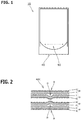
Fig. 1] Fig. 1 is a plan view showing a pouch according to an embodiment of the present invention. - [
Fig. 2] Fig. 2 is a cross-sectional view taken by cutting in the thickness direction along the line A-A inFig. 1 . - [
Fig. 3] Fig. 3 is a cross-sectional view showing an example of a method for three-dimensionally molding a film. - [
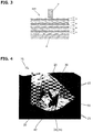
Fig. 4] Fig. 4 is a photograph of a pouch in which a protruding portion is formed on the inner film portion. - [
Fig. 5] Fig. 5 is a test result of a test conducted to confirm a suitable compression molding ratio. - [
Fig. 6] Fig. 6 is a cross-sectional view showing a modified example of the film overlapping section. - [
Fig. 7] Fig. 7 is an explanatory view schematically showing a modified example of the gusset portion. - [
Fig. 8] Fig. 8 is an explanatory view schematically showing a modified example of the gusset portion. - A
pouch 10 as a film molded body, which is an embodiment of the present invention, will be described below with reference to the drawings. - First, as shown in
Figs. 1 and4 , thepouch 10 has a bag-like shape formed by thermally fusing the outer edges of a film as a material, and serves for accommodating contents such as detergent and shampoo. - As shown in
Fig. 1 and Fig. 2 , a gusset portion (gore section) 40 obtained by disposing twoinner film portions 20 between twoouter film portions 30 is formed on the bottom of thepouch 10. - In the present embodiment, in the
gusset portion 40, as can be seen fromFig. 4 and (a) inFig. 7 , the twoinner film portions 20 have a folded-back portion 24 connected at the upper ends thereof. Moreover, eachouter film portion 30 is partially thermally fused to the opposinginner film portion 20 by thermally fusing afirst layer 21 of theinner film portion 20 and afirst layer 31 of theouter film portion 30 in athermal bonding portion 70 on the lower side (bottom side) thereof. - As shown in
Fig. 2 , eachinner film portion 20 is formed as a laminated film obtained by laminating and bonding thefirst layer 21 and asecond layer 22 having an elongation smaller than that of thefirst layer 21. - As shown in
Fig. 2 andFig. 3 , the twoinner film portions 20 are arranged so that thesecond layers 22 face each other when performing compression molding or folding thepouch 10. - As shown in
Fig. 2 , eachinner film portion 20 has a protrudingportion 23 protruding from thefirst layer 21 side to thesecond layer 22 side at afilm overlapping section 50 in thegusset portion 40 where thefilm portions - In the present embodiment, as shown in
Fig. 4 , theprotruding portion 23 is formed in a plurality of linear shapes in a direction (vertical direction in the present embodiment) intersecting with afolding line 25 of the folded-back portion 24 of theinner film portion 20. Further, theprotruding portion 23 is formed at a position where theinner film portions 20 overlap each other when thegusset portion 40 is folded. This is due to the method of forming the protrudingportion 23, and the method of forming the protrudingportion 23 will be described hereinbelow. - The protruding
portion 23 may have any specific shape limited to the above-described linear shape, and the number of theprotruding portions 23 may be one or more. - The protruding
portion 23 can function as a support for thegusset portion 40 while thegusset portion 40 is opened when thegusset portion 40 is expanded, and can maintain the open state of thegusset portion 40. In particular, in the standing pouch of the present embodiment, where the open state of thegusset portion 40 is maintained, the state of thepouch 10 that is inflated before filling the contents is unlikely to be restored, so that the opening property of thepouch 10 can be improved and the open state can be maintained. These linearprotruding portions 23 project toward the bottom side (outer side) in a state where thegusset portion 40 is expanded. - As shown in
Fig. 2 , theouter film portion 30 is formed as a laminated film obtained by laminating and bonding thefirst layer 31 and thesecond layer 32 having an elongation smaller than that of thefirst layer 31. - As shown in
Fig. 2 , eachouter film portion 30 is arranged such that thesecond layer 32 is located on the outer side of thepouch 10 with respect to thefirst layer 31. - When the
pouch 10 is shaped, thefirst layers 31 of theouter film portion 30 on the front and back sides are thermally fused to each other except the bottom part (top part, side part) of thepouch 10. - Examples of specific materials that can be used for the
first layers film portions - A stretched film can be suitably used as a specific material for the
second layers film portions - The thickness of the
first layers film portions second layers film portions first layers second layers - Further, the total thickness of each
film portion 20 and 30 (including each layer when eachfilm portion first layers second layers 22 and 32) is 30 µm to 300 µm. - Next, a method for three-dimensionally molding a film and a method for manufacturing a film molded body in the present embodiment will be described hereinbelow.
- First, the
pouch 10 having the gusset portion 40 (film overlapping section 50) is shaped. - Next, cold compression molding is performed in the thickness direction on the
film overlapping section 50 where thefilm portions Fig. 3 , a total of fourfilm portions film overlapping section 50 are sandwiched between and compressed by a pair of compression tools (molds) 60 arranged on the outer side of theouter film portions 30, and the compressed state is thereafter released to form a protrudingportion 23 by causing a part of theinner film portion 20 to protrude to thesecond layer 22 side, as shown inFig. 2 . As a result, it is possible to mold the protrudingportions 23 at positions where theinner film portions 20 overlap each other. - As shown in
Fig. 4 , with the above-described compression molding, no three-dimensional processing mark remains on theouter film portion 30, or even if a three-dimensional processing mark (not shown) is formed, only a small three-dimensional processing mark, that is, a three-dimensional processing mark with a smaller deformation amount in the thickness direction than the protrusion amount of the protrudingportion 23 in the thickness direction, remains. - The above-mentioned three-dimensional processing mark is a site where a part of the
outer film portion 30 is deformed into an uneven shape in the thickness direction by being compressed by thecompression tool 60, and when the three-dimensional processing mark is formed on theouter film portion 30, in a state where theinner film portion 20 and theouter film portion 30 are arranged to overlap, as shown inFig. 2 , the three-dimensional processing mark is formed in the vicinity of aposition 33 corresponding to the protrudingportion 23 of theinner film portion 20. - Here, the mechanism of the protrusion phenomenon that is manifested when the
inner film portion 20 is cold compressed in the thickness direction is not necessarily clear, but it is conceivable that the reason therefor is that after the compressive force is released, the thickness restoration behavior of theinner film portion 20 is such that thefirst layer 21 with relatively large elongation undergoes large restoration and thesecond layer 22 with relatively small elongation undergoes little restoration. - In addition, the appearance of the protrusion phenomenon on the
inner film portion 20 while no three-dimensional processing mark is left on theouter film portion 30 or a small three-dimensional processing mark is left on theouter film portion 30 when cold compression molding is performed in the thickness direction, as described hereinabove, is conceivably due to the fact that theinner film portion 20 extends in the plane direction of the film and is compressed in the thickness direction greater than theouter film portion 30 because when compression molding is performed on thefilm overlapping section 50 by acompression tool 60 from the outer side of theouter film portion 30, friction between the film portions (between theinner film portion 20 and theouter film portion 30, and between the inner film portions 20) is less than that between theouter film portion 30 and thecompression tool 60. - In the present embodiment, the two
inner film portions 20 are arranged between the twoouter film portions 30, but one or three or moreinner film portions 20 may be arranged. In that case, the protrudingportion 23 may be formed on thesecond layer 22 side of all of the three or moreinner film portions 20. - When two or more
inner film portions 20 are arranged between theouter film portions 30, at least two of the two or moreinner film portions 20 are preferably arranged so that thesecond layers 22 face each other. - Further, in order to form the protruding
portion 23 favorably, as can be seen from the test result shown inFig. 5 (test result when one film is used), it is preferable to design the compression molding ratio of theinner film portion 20 in the thickness direction to be from 20% or more to 65% or less of the thickness of theinner film portion 20. - Further, in order to form the protruding
portion 23 favorably, as can be seen from the test result shown inFig. 5 (test result when 3 to 6 films are used (including twoouter film portions 30, the remainder being inner film portion 20)), it is preferable to design the compression molding ratio of theinner film portion 20 and twoouter film portions 30 in the thickness direction to be from 20% or more to 35% or less of the total thickness of theinner film portion 20 and the twoouter film portions 30. - Where the compression molding ratio is set too low, the protruding
portion 23 is not formed in theinner film portion 20, and where the compression molding ratio is set too high, the elongation of theinner film portion 20 becomes excessive and damage such as tearing will occur in theinner film portion 20. - The test shown in
Fig. 5 was performed using thefilm portions - The embodiment of the present invention has been described in detail above, but the present invention is not limited to this embodiment, and various design changes can be made without departing from the present invention described in the claims.
- For example, in the configuration described in the abovementioned embodiment, the film molded body is the
pouch 10, but the specific form of the film molded body is not limited to thepouch 10, and the molded body may have any form, provided that a film is used as a constituent material of a part thereof. - Further, in the configuration described in the abovementioned embodiment, the
film overlapping section 50 to be cold-compressed in the thickness direction is set in thegusset portion 40 of thepouch 10, but the specific position of thefilm overlapping section 50 may be at any location as long as at least oneinner film portion 20 is arranged between the twoouter film portions 30 in a non-fixed state at this location. - Further, in the configuration described in the abovementioned embodiment, the
gusset portion 40 is formed at the bottom portion of thepouch 10, but the specific formation position of thegusset portion 40 may be any position, for example, such as the side portion of thepouch 10. - Further, in the configuration described in the abovementioned embodiment, as shown in (a) in
Fig. 7 , in thegusset portion 40, theinner film portion 20 is connected at the upper end thereof and folded back in a V shape, and eachouter film portion 30 is thermally bonded to the facinginner film portion 20. However, thegusset portion 40 may have a shape in which theinner film portion 20 folded back three times like a W shape is thermally bonded between theouter film portions 30, or the inner film portion may be folded a larger number of times. Further, the invention is not limited to this, and thegusset portion 40 composed of theouter film portions 30 and theinner film portion 20 may be formed by folding onefilm 3 times like an M shape, or thegusset portion 40 composed of theouter film portions 30 and theinner film portion 20 may be formed by folding one film twice like a Z shape, by folding one film four times like two successive Z shapes, by folding one film five times to sandwich a W-like shape, or by folding one film a larger number of times. - The abovementioned modified examples of the
gusset portion 40 are shown in (b) and (c) inFig. 7 and (a) and (b) inFig. 8 . Here, (a) to (c) inFig. 7 and (a) and (b) inFig. 8 schematically show thepouch 10 in a state before the protrudingportion 23 is formed. - Further, in the configuration described in the abovementioned embodiment, the two
inner film portions 20 are arranged between theouter film portions 30 in thefilm overlapping section 50, but the number of theinner film portions 20 may be one or more. For example, as shown inFig. 6 , compression molding may be performed by arranging only oneinner film portion 20 between the twoouter film portions 30. - Further, in the configuration described in the abovementioned embodiment, the
inner film portion 20 is formed by bonding only two layers, namely thefirst layer 21 and thesecond layer 22, but other layers (a metal layer made of aluminum or the like, a layer made of another stretched resin film, or the like) may be provided between thefirst layer 21 and thesecond layer 22 or outside thefirst layer 21 or thesecond layer 22. - Further, in the configuration described in the abovementioned embodiment, the protruding
portion 23 functions as a support when thegusset portion 40 spreads, but the protrudingportion 23 may be formed for a variety of purposes. For example, the protrudingportion 23 may be formed for the purpose of decorating with letters, patterns and character shapes, braille processing, slip prevention, and the like. As a result, it is possible to obtain an unprecedented decorating effect in the film molded body, and it is possible to enlarge the width of the universal design. - Further, in the configuration described in the abovementioned embodiment, the
outer film portion 30 is formed of a two-layer structure including thefirst layer 31 and thesecond layer 32, like theinner film portion 20, but theouter film portion 30 may have any specific form, for example, it may have a single layer structure as shown inFig. 6 , and any specific material may be used for theouter film portion 30. -
- 10
- Pouch (film molded body)
- 20
- Inner film portion
- 21
- First layer
- 22
- Second layer
- 23
- Protruding portion
- 24
- Folded-back portion
- 25
- Folding line
- 30
- Outer film portion
- 31
- First layer
- 32
- Second layer
- 40
- Gusset portion
- 50
- Film overlapping section
- 60
- Compression tool
- 70
- Thermal bonding portion
Claims (7)
- A method for three-dimensionally molding a film, the method comprising performing cold compression molding in a thickness direction on a film overlapping section in which at least one inner film portion including a first layer and a second layer having an elongation smaller than that of the first layer is arranged between two outer film portions in a non-fixed state with respect to the outer film portions, thereby causing the inner film portion to protrude toward the second layer side at the film overlapping section.
- The method for three-dimensionally molding a film according to claim 1, wherein a compression molding ratio of the inner film portion in the thickness direction is 20% or more of a thickness of the inner film portion.
- The method for three-dimensionally molding a film according to claim 1 or 2, wherein a compression molding ratio of the inner film portion and the two outer film portions in the thickness direction is 20% or more of a total thickness of the inner film portion and the two outer film portions.
- A method for manufacturing a film molded body in which at least one inner film portion including a first layer and a second layer having an elongation smaller than that of the first layer forms a gusset portion between two outer film portions, the method comprising
performing cold compression molding in a thickness direction on the outer film portions at a film overlapping section in the gusset portion, thereby causing the inner film portion to protrude toward the second layer side at the film overlapping section. - The method for manufacturing a film molded body according to claim 4, wherein the at least one inner film portion comprises two or more inner film portions, and when the compression molding is performed, at least two of the two or more inner film portions in the gusset portion are arranged such that the second layer of one of the at least two faces the second layer of another of the at least two.
- A film molded body in which at least one inner film portion including a first layer and a second layer having an elongation smaller than that of the first layer forms a gusset portion between two outer film portions, wherein
the inner film portion in the gusset portion has a protruding portion that protrudes to the second layer side at a film overlapping section. - The film molded body according to claim 6, wherein the at least one inner film portion comprises two or more inner film portions, and at least two of the two or more inner film portions in the gusset portion are arranged so that the second layer of one of the at least two faces the second layer of another of the at least two.
Applications Claiming Priority (2)
| Application Number | Priority Date | Filing Date | Title |
|---|---|---|---|
| JP2018031838A JP7517787B2 (en) | 2018-02-26 | 2018-02-26 | Method for three-dimensionally forming a film, method for producing a film molded body, and film molded body |
| PCT/JP2019/000047 WO2019163305A1 (en) | 2018-02-26 | 2019-01-07 | Method for three-dimensionally molding film, method for manufacturing film molded body, and film molded body |
Publications (2)
| Publication Number | Publication Date |
|---|---|
| EP3760426A1 true EP3760426A1 (en) | 2021-01-06 |
| EP3760426A4 EP3760426A4 (en) | 2021-11-17 |
Family
ID=67687516
Family Applications (1)
| Application Number | Title | Priority Date | Filing Date |
|---|---|---|---|
| EP19757929.5A Withdrawn EP3760426A4 (en) | 2018-02-26 | 2019-01-07 | Method for three-dimensionally molding film, method for manufacturing film molded body, and film molded body |
Country Status (6)
| Country | Link |
|---|---|
| US (1) | US20200384717A1 (en) |
| EP (1) | EP3760426A4 (en) |
| JP (1) | JP7517787B2 (en) |
| CN (1) | CN111770832B (en) |
| TW (1) | TWI688481B (en) |
| WO (1) | WO2019163305A1 (en) |
Families Citing this family (3)
| Publication number | Priority date | Publication date | Assignee | Title |
|---|---|---|---|---|
| WO2022144750A1 (en) * | 2020-12-30 | 2022-07-07 | Speggiorin Lorenzo | Packaging machine for forming doy-pack bags |
| TWI909064B (en) * | 2021-07-21 | 2025-12-21 | 義大利商沙克米機械商業合作艾莫勒精簡公司 | Apparatus and method for cutting closures for containers |
| KR102778421B1 (en) * | 2022-06-17 | 2025-03-11 | 에스케이마이크로웍스 주식회사 | Polyester film and foldable display apparatus comprising same |
Family Cites Families (17)
| Publication number | Priority date | Publication date | Assignee | Title |
|---|---|---|---|---|
| US4373979A (en) * | 1980-09-26 | 1983-02-15 | Workman Bag Company Ltd. | Sealed bags of plastic materials |
| JP4370768B2 (en) | 2002-10-22 | 2009-11-25 | 東洋製罐株式会社 | Method of forming bag-shaped container with embossed pattern, molding device for bag-shaped container with embossed pattern, and bag-shaped container with embossed pattern |
| TW200500271A (en) * | 2002-10-24 | 2005-01-01 | Kao Corp | Self-supporting bag |
| JP2006219168A (en) * | 2005-02-10 | 2006-08-24 | Kao Corp | bag |
| JP4857734B2 (en) * | 2005-11-25 | 2012-01-18 | 富士ゼロックス株式会社 | Method for producing cylindrical thin film elastic body |
| JP2008290737A (en) | 2007-05-23 | 2008-12-04 | Toyo Seikan Kaisha Ltd | Self-standing packaging bag |
| JP5150433B2 (en) | 2008-09-24 | 2013-02-20 | 藤森工業株式会社 | Laminated film processing method |
| JP5604820B2 (en) * | 2009-07-15 | 2014-10-15 | ダイキン工業株式会社 | Molded body and method for producing hollow molded body |
| JP6051696B2 (en) * | 2012-09-04 | 2016-12-27 | 東洋製罐株式会社 | Three-dimensional forming method of laminated film |
| JP6252033B2 (en) * | 2013-08-19 | 2017-12-27 | 東洋製罐株式会社 | Synthetic resin film bonding method, apparatus and packaging pouch |
| JP6520042B2 (en) * | 2014-10-23 | 2019-05-29 | 東洋製罐株式会社 | Three-dimensional molding method of laminated film body |
| JP6516149B2 (en) * | 2015-03-18 | 2019-05-22 | 株式会社リコー | Powder material for three-dimensional modeling, kit for three-dimensional modeling, and method for producing three-dimensional object |
| WO2017042905A1 (en) | 2015-09-09 | 2017-03-16 | 花王株式会社 | Sheet material container |
| JP7024409B2 (en) * | 2015-12-15 | 2022-02-24 | 東洋製罐株式会社 | Package |
| CN108463337B (en) * | 2016-01-05 | 2020-10-30 | 东洋制罐株式会社 | Three-dimensional molding method of resin-made packaging material and resin-made packaging material |
| JP6688666B2 (en) * | 2016-04-15 | 2020-04-28 | 株式会社細川洋行 | Gazette bag and method of manufacturing gazette bag |
| JP6855181B2 (en) * | 2016-06-30 | 2021-04-07 | キヤノン株式会社 | 3D modeling device and manufacturing method of 3D modeled object |
-
2018
- 2018-02-26 JP JP2018031838A patent/JP7517787B2/en active Active
-
2019
- 2019-01-07 EP EP19757929.5A patent/EP3760426A4/en not_active Withdrawn
- 2019-01-07 CN CN201980013738.2A patent/CN111770832B/en not_active Expired - Fee Related
- 2019-01-07 WO PCT/JP2019/000047 patent/WO2019163305A1/en not_active Ceased
- 2019-01-09 TW TW108100874A patent/TWI688481B/en not_active IP Right Cessation
-
2020
- 2020-08-25 US US17/001,912 patent/US20200384717A1/en not_active Abandoned
Also Published As
| Publication number | Publication date |
|---|---|
| JP7517787B2 (en) | 2024-07-17 |
| CN111770832B (en) | 2022-08-09 |
| TW201940317A (en) | 2019-10-16 |
| EP3760426A4 (en) | 2021-11-17 |
| CN111770832A (en) | 2020-10-13 |
| US20200384717A1 (en) | 2020-12-10 |
| JP2019147256A (en) | 2019-09-05 |
| TWI688481B (en) | 2020-03-21 |
| WO2019163305A1 (en) | 2019-08-29 |
Similar Documents
| Publication | Publication Date | Title |
|---|---|---|
| US20200384717A1 (en) | Method for three-dimensionally molding film, method for manufacturing film molded body, and film molded body | |
| US7211035B2 (en) | Method for manufacturing reclosable packaging bag | |
| US6808666B2 (en) | Zipper tape for a bag and method of producing the same | |
| EP1967460A2 (en) | Packaging bag and method for manufacturing same | |
| AU2017247389A1 (en) | Composite packaging, packaging laminate, and packaging casing blank for a composite packaging | |
| JP6051696B2 (en) | Three-dimensional forming method of laminated film | |
| WO2008035494A1 (en) | Easily tearable fastener tape, method of producing the fastener tape, packaging bag with easily tearable fastener tape, and device and method for producing the packaging bag | |
| JP6259351B2 (en) | Packaging bag and manufacturing method thereof | |
| CN107264912A (en) | Composite packaging part, package laminated product and package sleeve blank for composite packaging part | |
| JP6496110B2 (en) | Storage body with fastener, its fastener, and continuous sheet for storage body | |
| JP5514471B2 (en) | Molded product and manufacturing method thereof | |
| KR102877218B1 (en) | Tape, zipper tape, containers with tape attached and containers with zipper tape attached | |
| JP6111653B2 (en) | Packaging bag | |
| JP2013209108A (en) | Pouch container | |
| JP7514073B2 (en) | Packaging Bag | |
| EP2885120B1 (en) | Method of making a plastic film with integrated zipper closure, and plastic bag having an integrated zipper closure | |
| JP3364437B2 (en) | Self-supporting packaging bag | |
| JP7384094B2 (en) | Paper container with zipper | |
| EP4552993A1 (en) | Pouch | |
| JP6512336B2 (en) | Packaging bag | |
| EP4552992A1 (en) | Pouch | |
| JP7589684B2 (en) | Method for three-dimensional processing of film, compression mold, film, and film molded body | |
| JP3221942U (en) | Side seal type CPP handbag | |
| CN100374355C (en) | Plastic film mouth-locking bag and its making method | |
| JP2010132311A (en) | Multi-cell packaging bag, and method for manufacturing package using the same |
Legal Events
| Date | Code | Title | Description |
|---|---|---|---|
| STAA | Information on the status of an ep patent application or granted ep patent |
Free format text: STATUS: THE INTERNATIONAL PUBLICATION HAS BEEN MADE |
|
| PUAI | Public reference made under article 153(3) epc to a published international application that has entered the european phase |
Free format text: ORIGINAL CODE: 0009012 |
|
| STAA | Information on the status of an ep patent application or granted ep patent |
Free format text: STATUS: REQUEST FOR EXAMINATION WAS MADE |
|
| 17P | Request for examination filed |
Effective date: 20200924 |
|
| AK | Designated contracting states |
Kind code of ref document: A1 Designated state(s): AL AT BE BG CH CY CZ DE DK EE ES FI FR GB GR HR HU IE IS IT LI LT LU LV MC MK MT NL NO PL PT RO RS SE SI SK SM TR |
|
| AX | Request for extension of the european patent |
Extension state: BA ME |
|
| DAV | Request for validation of the european patent (deleted) | ||
| DAX | Request for extension of the european patent (deleted) | ||
| A4 | Supplementary search report drawn up and despatched |
Effective date: 20211020 |
|
| RIC1 | Information provided on ipc code assigned before grant |
Ipc: B29L 31/00 20060101ALN20211014BHEP Ipc: B65D 30/20 20060101ALI20211014BHEP Ipc: B65D 30/08 20060101ALI20211014BHEP Ipc: B29C 43/20 20060101ALI20211014BHEP Ipc: B31F 1/08 20060101ALI20211014BHEP Ipc: B29C 43/00 20060101ALI20211014BHEP Ipc: B32B 27/08 20060101AFI20211014BHEP |
|
| REG | Reference to a national code |
Ref country code: DE Ref legal event code: R079 Free format text: PREVIOUS MAIN CLASS: B31B0070640000 Ipc: B32B0027080000 |
|
| GRAP | Despatch of communication of intention to grant a patent |
Free format text: ORIGINAL CODE: EPIDOSNIGR1 |
|
| STAA | Information on the status of an ep patent application or granted ep patent |
Free format text: STATUS: GRANT OF PATENT IS INTENDED |
|
| RIC1 | Information provided on ipc code assigned before grant |
Ipc: B29L 31/00 20060101ALN20230209BHEP Ipc: B32B 27/36 20060101ALI20230209BHEP Ipc: B32B 27/34 20060101ALI20230209BHEP Ipc: B32B 27/32 20060101ALI20230209BHEP Ipc: B32B 27/30 20060101ALI20230209BHEP Ipc: B32B 15/20 20060101ALI20230209BHEP Ipc: B32B 15/09 20060101ALI20230209BHEP Ipc: B32B 15/088 20060101ALI20230209BHEP Ipc: B32B 15/085 20060101ALI20230209BHEP Ipc: B32B 15/082 20060101ALI20230209BHEP Ipc: B65D 30/20 20060101ALI20230209BHEP Ipc: B65D 30/08 20060101ALI20230209BHEP Ipc: B29C 43/20 20060101ALI20230209BHEP Ipc: B31F 1/08 20060101ALI20230209BHEP Ipc: B29C 43/00 20060101ALI20230209BHEP Ipc: B32B 27/08 20060101AFI20230209BHEP |
|
| INTG | Intention to grant announced |
Effective date: 20230222 |
|
| STAA | Information on the status of an ep patent application or granted ep patent |
Free format text: STATUS: THE APPLICATION IS DEEMED TO BE WITHDRAWN |
|
| 18D | Application deemed to be withdrawn |
Effective date: 20230705 |