EP3759982B1 - Auf entfernungsmessung basierte ortsdienste in der drahtlosen kommunikation - Google Patents
Auf entfernungsmessung basierte ortsdienste in der drahtlosen kommunikation Download PDFInfo
- Publication number
- EP3759982B1 EP3759982B1 EP19711467.1A EP19711467A EP3759982B1 EP 3759982 B1 EP3759982 B1 EP 3759982B1 EP 19711467 A EP19711467 A EP 19711467A EP 3759982 B1 EP3759982 B1 EP 3759982B1
- Authority
- EP
- European Patent Office
- Prior art keywords
- ranging
- location
- ran
- lmf
- core network
- Prior art date
- Legal status (The legal status is an assumption and is not a legal conclusion. Google has not performed a legal analysis and makes no representation as to the accuracy of the status listed.)
- Active
Links
Images






Classifications
-
- H—ELECTRICITY
- H04—ELECTRIC COMMUNICATION TECHNIQUE
- H04W—WIRELESS COMMUNICATION NETWORKS
- H04W4/00—Services specially adapted for wireless communication networks; Facilities therefor
- H04W4/02—Services making use of location information
- H04W4/023—Services making use of location information using mutual or relative location information between multiple location based services [LBS] targets or of distance thresholds
-
- G—PHYSICS
- G01—MEASURING; TESTING
- G01S—RADIO DIRECTION-FINDING; RADIO NAVIGATION; DETERMINING DISTANCE OR VELOCITY BY USE OF RADIO WAVES; LOCATING OR PRESENCE-DETECTING BY USE OF THE REFLECTION OR RERADIATION OF RADIO WAVES; ANALOGOUS ARRANGEMENTS USING OTHER WAVES
- G01S5/00—Position-fixing by co-ordinating two or more direction or position line determinations; Position-fixing by co-ordinating two or more distance determinations
- G01S5/02—Position-fixing by co-ordinating two or more direction or position line determinations; Position-fixing by co-ordinating two or more distance determinations using radio waves
- G01S5/10—Position of receiver fixed by co-ordinating a plurality of position lines defined by path-difference measurements, e.g. omega or decca systems
-
- H—ELECTRICITY
- H04—ELECTRIC COMMUNICATION TECHNIQUE
- H04W—WIRELESS COMMUNICATION NETWORKS
- H04W4/00—Services specially adapted for wireless communication networks; Facilities therefor
- H04W4/02—Services making use of location information
- H04W4/029—Location-based management or tracking services
-
- H—ELECTRICITY
- H04—ELECTRIC COMMUNICATION TECHNIQUE
- H04W—WIRELESS COMMUNICATION NETWORKS
- H04W4/00—Services specially adapted for wireless communication networks; Facilities therefor
- H04W4/30—Services specially adapted for particular environments, situations or purposes
- H04W4/40—Services specially adapted for particular environments, situations or purposes for vehicles, e.g. vehicle-to-pedestrians [V2P]
-
- H—ELECTRICITY
- H04—ELECTRIC COMMUNICATION TECHNIQUE
- H04W—WIRELESS COMMUNICATION NETWORKS
- H04W64/00—Locating users or terminals or network equipment for network management purposes, e.g. mobility management
-
- H—ELECTRICITY
- H04—ELECTRIC COMMUNICATION TECHNIQUE
- H04W—WIRELESS COMMUNICATION NETWORKS
- H04W72/00—Local resource management
- H04W72/12—Wireless traffic scheduling
-
- H—ELECTRICITY
- H04—ELECTRIC COMMUNICATION TECHNIQUE
- H04W—WIRELESS COMMUNICATION NETWORKS
- H04W72/00—Local resource management
- H04W72/20—Control channels or signalling for resource management
-
- H—ELECTRICITY
- H04—ELECTRIC COMMUNICATION TECHNIQUE
- H04W—WIRELESS COMMUNICATION NETWORKS
- H04W72/00—Local resource management
- H04W72/20—Control channels or signalling for resource management
- H04W72/23—Control channels or signalling for resource management in the downlink direction of a wireless link, i.e. towards a terminal
-
- H—ELECTRICITY
- H04—ELECTRIC COMMUNICATION TECHNIQUE
- H04W—WIRELESS COMMUNICATION NETWORKS
- H04W72/00—Local resource management
- H04W72/50—Allocation or scheduling criteria for wireless resources
- H04W72/51—Allocation or scheduling criteria for wireless resources based on terminal or device properties
-
- H—ELECTRICITY
- H04—ELECTRIC COMMUNICATION TECHNIQUE
- H04W—WIRELESS COMMUNICATION NETWORKS
- H04W76/00—Connection management
- H04W76/20—Manipulation of established connections
- H04W76/27—Transitions between radio resource control [RRC] states
-
- H—ELECTRICITY
- H04—ELECTRIC COMMUNICATION TECHNIQUE
- H04W—WIRELESS COMMUNICATION NETWORKS
- H04W4/00—Services specially adapted for wireless communication networks; Facilities therefor
- H04W4/02—Services making use of location information
-
- H—ELECTRICITY
- H04—ELECTRIC COMMUNICATION TECHNIQUE
- H04W—WIRELESS COMMUNICATION NETWORKS
- H04W4/00—Services specially adapted for wireless communication networks; Facilities therefor
- H04W4/06—Selective distribution of broadcast services, e.g. multimedia broadcast multicast service [MBMS]; Services to user groups; One-way selective calling services
-
- H—ELECTRICITY
- H04—ELECTRIC COMMUNICATION TECHNIQUE
- H04W—WIRELESS COMMUNICATION NETWORKS
- H04W4/00—Services specially adapted for wireless communication networks; Facilities therefor
- H04W4/70—Services for machine-to-machine communication [M2M] or machine type communication [MTC]
-
- H—ELECTRICITY
- H04—ELECTRIC COMMUNICATION TECHNIQUE
- H04W—WIRELESS COMMUNICATION NETWORKS
- H04W76/00—Connection management
- H04W76/10—Connection setup
- H04W76/11—Allocation or use of connection identifiers
Definitions
- the technology discussed below relates generally to wireless communication systems, and more particularly, to location services with support for ranging in a wireless communication system and related communication devices.
- a wireless network can provide various services in addition to voice and data communication.
- One such service is location service (LCS) that can be used by a user to determine a position or location.
- LCS may utilize one or more positioning methods to determine the location of the user, for example, a user equipment (UE) or vehicle.
- LCS may use an observed time difference of arrival (OTDOA) method, Assisted Global Navigation Satellite System (A-GNSS) method, and/or uplink-time difference of arrival (UTDOA) method.
- OTDOA observed time difference of arrival
- A-GNSS Assisted Global Navigation Satellite System
- UTDOA uplink-time difference of arrival
- positioning generally refers to a process of determining the position, location, and/or velocity of a device using radio signals.
- LCS may be implemented with support of ranging based positioning.
- D2D device-to-device
- a wireless communication device may be a UE such as a portable cellular device, or may be a vehicle, such as an automobile, a drone, or may be any other connected device.
- the D2D communication may be referred to as vehicle-to-vehicle (V2V) communication.
- V2X vehicle-to-everything
- V2I vehicle-to-infrastructure
- V2N vehicle-to-network
- V2P vehicle-to-pedestrian
- V2X communications and particularly V2V communications will become more and more important in the future for collision avoidance and autonomous driving applications.
- a vehicle that uses V2X communications in ranging operations can assist a network in determining the location of the vehicle.
- WO2017027450A1 discloses a system and method to measure UE-to-UE distance based on D2D sidelink channel.
- aspects of the present disclosure relate to a network architecture with support for ranging based location services (LCS) in wireless communication.
- LCD ranging based location services
- the first RAN node may include a communication interface configured for wireless communication, a memory, and a processor operatively coupled to the communication interface and the memory.
- the processor and the memory may be configured to perform ranging based positioning and related location services.
- the first RAN node receives a registration request from a user equipment (UE), and the connection request indicates that the UE supports a ranging based location service session.
- the first RAN node receives an Internal identifier (ID) for identifying information, associated with the UE, between the first RAN node and a core network during the ranging based location service session.
- ID Internal identifier
- the first RAN node allocates radio resources, associated with the Internal ID, to the UE for performing a ranging operation in the ranging based location service session involving a plurality of devices including the UE.
- the first RAN node transmits a registration response to the UE, indicating the allocated radio resources for performing the ranging operation.
- the UE may include a communication interface configured for wireless communication, a memory, and a processor operatively coupled to the communication interface and the memory.
- the processor and the memory may be configured to perform ranging based positioning and related location services.
- the UE transmits a registration request to a radio access network (RAN), and the registration request indicates that the UE supports a ranging based location service session.
- the UE from the RAN, receives an allocation of radio resources for performing a ranging operation and an External identifier (ID) allocated by a core network for identifying a location result of the UE based on the ranging operation.
- the UE receives the location result generated by the core network in the ranging based location service session, and the location result is identified by the External ID associated with the UE.
- ID External identifier
- Implementations may range a spectrum from chip-level or modular components to non-modular, non-chip-level implementations and further to aggregate, distributed, or OEM devices or systems incorporating one or more aspects of the described innovations.
- devices incorporating described aspects and features may also necessarily include additional components and features for implementation and practice of claimed and described embodiments.
- transmission and reception of wireless signals necessarily includes a number of components for analog and digital purposes (e.g., hardware components including antenna, RF-chains, power amplifiers, modulators, buffer, processor(s), interleaver, adders/summers, etc.).
- innovations described herein may be practiced in a wide variety of devices, chip-level components, systems, distributed arrangements, end-user devices, etc. of varying sizes, shapes and constitution.
- This disclosure describes a network architecture with support for ranging based location services (LCS).
- a user equipment (UE) registers with a network
- the UE can indicate support of ranging based LCS.
- a radio access network (RAN) node receives the registration request and indicates to the core network that the UE supports a ranging based location service session.
- the network uses an internal identifier (ID) for identifying information associated with the UE in communication between the RAN node and the core network during the ranging based location service session, and an external ID associated with the UE for transmitting the location results back to the UE.
- ID internal identifier
- the various concepts presented throughout this disclosure may be implemented across a broad variety of telecommunication systems, network architectures, and communication standards.
- the wireless communication system 100 includes three interacting domains: a core network 102, a radio access network (RAN) 104, and a user equipment (UE) 106.
- the UE 106 may be enabled to carry out data communication with an external data network 110, such as (but not limited to) the Internet.
- the RAN 104 may implement any suitable wireless communication technology or technologies to provide radio access to the UE 106.
- the RAN 104 may operate according to 3 rd Generation Partnership Project (3GPP) New Radio (NR) specifications, often referred to as 5G.
- 3GPP 3 rd Generation Partnership Project
- NR New Radio
- the RAN 104 may operate under a hybrid of 5G NR and Evolved Universal Terrestrial Radio Access Network (eUTRAN) standards, often referred to as LTE.
- eUTRAN Evolved Universal Terrestrial Radio Access Network
- the 3GPP refers to this hybrid RAN as a next-generation RAN (NG-RAN).
- NG-RAN next-generation RAN
- many other examples may be utilized within the scope of the present disclosure.
- a base station is a network element in a radio access network responsible for radio transmission and reception in one or more cells to or from a UE.
- a base station may variously be referred to by those skilled in the art as a base transceiver station (BTS), a radio base station, a radio transceiver, a transceiver function, a basic service set (BSS), an extended service set (ESS), an access point (AP), a Node B (NB), an eNode B (eNB), a gNode B (gNB), or some other suitable terminology.
- BTS base transceiver station
- BSS basic service set
- ESS extended service set
- AP access point
- NB Node B
- eNB eNode B
- gNB gNode B
- the radio access network 104 is further illustrated supporting wireless communication for multiple mobile apparatuses.
- a mobile apparatus may be referred to as user equipment (UE) in 3GPP standards, but may also be referred to by those skilled in the art as a mobile station (MS), a subscriber station, a mobile unit, a subscriber unit, a wireless unit, a remote unit, a mobile device, a wireless device, a wireless communications device, a remote device, a mobile subscriber station, an access terminal (AT), a mobile terminal, a wireless terminal, a remote terminal, a handset, a terminal, a user agent, a mobile client, a client, or some other suitable terminology.
- a UE may be an apparatus, a vehicle, or a component of a vehicle that provides a user with access to network services.
- a "mobile” apparatus need not necessarily have a capability to move, and may be stationary.
- the term mobile apparatus or mobile device broadly refers to a diverse array of devices and technologies.
- UEs may include a number of hardware structural components sized, shaped, and arranged to help in communication; such components can include antennas, antenna arrays, RF chains, amplifiers, one or more processors, etc. electrically coupled to each other.
- a mobile apparatus examples include a mobile, a cellular (cell) phone, a smart phone, a session initiation protocol (SIP) phone, a laptop, a personal computer (PC), a notebook, a netbook, a smartbook, a tablet, a personal digital assistant (PDA), and a broad array of embedded systems, e.g., corresponding to an "Internet of things" (loT).
- a mobile apparatus may additionally be an automotive or other transportation vehicle, a remote sensor or actuator, a robot or robotics device, a satellite radio, a global navigation satellite system (GNSS) device, an object tracking device, a drone, a multi-copter, a quad-copter, a remote control device, a consumer and/or wearable device, such as eyewear, a wearable camera, a virtual reality device, a smart watch, a health or fitness tracker, a digital audio player (e.g., MP3 player), a camera, a game console, etc.
- GNSS global navigation satellite system
- a mobile apparatus may additionally be a digital home or smart home device such as a home audio, video, and/or multimedia device, an appliance, a vending machine, intelligent lighting, a home security system, a smart meter, etc.
- a mobile apparatus may additionally be a smart energy device, a security device, a solar panel or solar array, a municipal infrastructure device controlling electric power (e.g., a smart grid), lighting, water, etc.; an industrial automation and enterprise device; a logistics controller; agricultural equipment; military defense equipment, vehicles, aircraft, ships, and weaponry, etc.
- a mobile apparatus may provide for connected medicine or telemedicine support, e.g., health care at a distance.
- Telehealth devices may include telehealth monitoring devices and telehealth administration devices, whose communication may be given preferential treatment or prioritized access over other types of information, e.g., in terms of prioritized access for transport of critical service data, and/or relevant QoS for transport of critical service data.
- Wireless communication between a RAN 104 and a UE 106 may be described as utilizing an air interface.
- Transmissions over the air interface from a base station (e.g., base station 108) to one or more UEs (e.g., UE 106) may be referred to as downlink (DL) transmission.
- the term downlink may refer to a point-to-multipoint transmission originating at a scheduling entity (described further below; e.g., base station 108). Another way to describe this scheme may be to use the term broadcast channel multiplexing.
- Transmissions from a UE (e.g., UE 106) to a base station (e.g., base station 108) may be referred to as uplink (UL) transmissions.
- the term uplink may refer to a point-to-point transmission originating at a scheduled entity (described further below; e.g., UE 106).
- a scheduling entity e.g., a base station 108 allocates resources for communication among some or all devices and equipment within its service area or cell.
- the scheduling entity may be responsible for scheduling, assigning, reconfiguring, and releasing resources for one or more scheduled entities. That is, for scheduled communication, UEs 106, which may be scheduled entities, may utilize resources allocated by the scheduling entity 108.
- Base stations 108 are not the only entities that may function as scheduling entities. That is, in some examples, a UE may function as a scheduling entity, scheduling resources for one or more scheduled entities (e.g., one or more other UEs).
- a scheduling entity 108 may broadcast downlink traffic 112 to one or more scheduled entities 106.
- the scheduling entity 108 is a node or device responsible for scheduling traffic in a wireless communication network, including the downlink traffic 112 and, in some examples, uplink traffic 116 from one or more scheduled entities 106 to the scheduling entity 108.
- the scheduled entity 106 is a node or device that receives downlink control information 114, including but not limited to scheduling information (e.g., a grant), synchronization or timing information, or other control information from another entity in the wireless communication network such as the scheduling entity 108.
- base stations 108 may include a backhaul interface for communication with a backhaul portion 120 of the wireless communication system.
- the backhaul 120 may provide a link between a base station 108 and the core network 102.
- a backhaul network may provide interconnection between the respective base stations 108.
- Various types of backhaul interfaces may be employed, such as a direct physical connection, a virtual network, or the like using any suitable transport network.
- the core network 102 may be a part of the wireless communication system 100 and may be independent of the radio access technology used in the RAN 104.
- the core network 102 may be configured according to 5G standards (e.g., 5GC).
- the core network 102 may be configured according to a 4G evolved packet core (EPC), or any other suitable standard or configuration.
- 5G standards e.g., 5GC
- EPC 4G evolved packet core
- FIG. 2 is a conceptual illustration of an example of a radio access network 200 (RAN).
- the RAN 200 may be the same as the RAN 104 described above and illustrated in FIG. 1 .
- the geographic area covered by the RAN 200 may be divided into cellular regions (cells) that can be uniquely identified by a user equipment (UE) based on an identification broadcasted from one access point or base station.
- FIG. 2 illustrates macrocells 202, 204, and 206, and a small cell 208, each of which may include one or more sectors (not shown) or zones.
- a sector is a sub-area of a cell. All sectors within one cell are served by the same base station.
- a radio link within a sector can be identified by a single logical identification belonging to that sector.
- the multiple sectors within a cell can be formed by groups of antennas with each antenna responsible for communication with UEs in a portion of the cell.
- FIG. 2 two base stations 210 and 212 are shown in cells 202 and 204; and a third base station 214 is shown controlling a remote radio head (RRH) 216 in cell 206. That is, a base station can have an integrated antenna or can be connected to an antenna or RRH by feeder cables.
- a base station can have an integrated antenna or can be connected to an antenna or RRH by feeder cables.
- the cells 202, 204, and 126 may be referred to as macrocells, as the base stations 210, 212, and 214 support cells having a large size.
- a base station 218 is shown in the small cell 208 (e.g., a microcell, picocell, femtocell, home base station, home Node B, home eNode B, etc.) which may overlap with one or more macrocells.
- the cell 208 may be referred to as a small cell, as the base station 218 supports a cell having a relatively small size. Cell sizing can be done according to system design as well as component constraints.
- the radio access network 200 may include any number of wireless base stations and cells. Further, a relay node may be deployed to extend the size or coverage area of a given cell.
- the base stations 210, 212, 214, 218 provide wireless access points to a core network for any number of mobile apparatuses. In some examples, the base stations 210, 212, 214, and/or 218 may be the same as the base station/scheduling entity 108 described above and illustrated in FIG. 1 .
- FIG. 2 further includes a quadcopter or drone 220, which may be configured to function as a base station. That is, in some examples, a cell may not necessarily be stationary, and the geographic area of the cell may move according to the location of a mobile base station such as the quadcopter 220.
- a quadcopter or drone 220 may be configured to function as a base station. That is, in some examples, a cell may not necessarily be stationary, and the geographic area of the cell may move according to the location of a mobile base station such as the quadcopter 220.
- the cells may include UEs that may be in communication with one or more sectors of each cell.
- each base station 210, 212, 214, 218, and 220 may be configured to provide an access point to a core network 102 (see FIG. 1 ) for all the UEs in the respective cells.
- UEs 222 and 224 may be in communication with base station 210; UEs 226 and 228 may be in communication with base station 212; UEs 230 and 232 may be in communication with base station 214 by way of RRH 216; UE 234 may be in communication with base station 218; and UE 236 may be in communication with mobile base station 220.
- the UEs 222, 224, 226, 228, 230, 232, 234, 236, 238, 240, and/or 242 may be the same as the UFJscheduled entity 106 described above and illustrated in FIG. 1 .
- a mobile network node e.g., quadcopter 220
- quadcopter 220 may be configured to function as a UE.
- the quadcopter 220 may operate within cell 202 by communicating with base station 210.
- sidelink signals may be used between UEs without necessarily relying on scheduling or control information from a base station.
- two or more UEs e.g., UEs 226 and 228, may communicate with each other using peer-to-peer (P2P), device-to-device (D2D), vehicle-to-vehicle (V2V), vehicle-to-everything (V2X), or sidelink signals 227 without relaying that communication through a base station (e.g., base station 212).
- UE 238 is illustrated communicating with UEs 240 and 242.
- the UE 238 may function as a scheduling entity or a primary sidelink device, and UEs 240 and 242 may function as a scheduled entity or a non-primary (e.g., secondary) sidelink device.
- a UE may function as a scheduling entity in a D2D, P2P, V2X, or V2V network, and/or in a mesh network.
- UEs 240 and 242 may optionally communicate directly with one another in addition to communicating with the scheduling entity 238.
- a scheduling entity and one or more scheduled entities may communicate utilizing the scheduled resources.
- the ability for a UE to communicate while moving, independent of its location is referred to as mobility.
- the various physical channels between the UE and the radio access network are generally set up, maintained, and released under the control of an access and mobility management function (AMF, not illustrated in FIG. 2 , part of the core network 102 in FIG. 1 ), which may include a security context management function (SCMF) that manages the security context for both the control plane and the user plane functionality, and a security anchor function (SEAF) that performs authentication.
- AMF access and mobility management function
- SCMF security context management function
- SEAF security anchor function
- the AMF is an example of a core network entity.
- the synchronization signal transmitted by the base stations 210, 212, and 214/216 may be unified, the synchronization signal may not identify a particular cell, but rather may identify a zone of multiple cells operating on the same frequency and/or with the same timing.
- the use of zones in 5G networks or other next-generation communication networks enables the uplink-based mobility framework and improves the efficiency of both the UE and the network, since the number of mobility messages that need to be exchanged between the UE and the network may be reduced.
- the air interface in the radio access network 200 may utilize licensed spectrum, unlicensed spectrum, or shared spectrum.
- Licensed spectrum provides for exclusive use of a portion of the spectrum, generally by virtue of a mobile network operator purchasing a license from a government regulatory body.
- Unlicensed spectrum provides for shared use of a portion of the spectrum without need for a government-granted license. While compliance with some technical rules is generally still required to access unlicensed spectrum, generally, any operator or device may gain access.
- Shared spectrum may fall between licensed and unlicensed spectrum, wherein technical rules or limitations may be required to access the spectrum, but the spectrum may still be shared by multiple operators and/or multiple RATs.
- the holder of a license for a portion of licensed spectrum may provide licensed shared access (LSA) to share that spectrum with other parties, e.g., with suitable licenseedetermined conditions to gain access.
- LSA licensed shared access
- the air interface in the radio access network 200 may utilize one or more duplexing algorithms.
- Duplex refers to a point-to-point communication link where both endpoints can communicate with one another in both directions.
- Full duplex means both endpoints can simultaneously communicate with one another.
- Half duplex means only one endpoint can send information to the other at a time.
- a full duplex channel generally relies on physical isolation of a transmitter and receiver, and suitable interference cancellation technologies.
- Full duplex emulation is frequently implemented for wireless links by utilizing frequency division duplex (FDD) or time division duplex (TDD).
- FDD frequency division duplex
- TDD time division duplex
- transmissions in different directions on a given channel are separated from one another using time division multiplexing. That is, at sometimes the channel is dedicated for transmissions in one direction, while at other times the channel is dedicated for transmissions in the other direction, where the direction may change very rapidly, e.g., several times per slot.
- channel coding may be used. That is, wireless communication may generally utilize a suitable error correcting block code.
- an information message or sequence is split up into code blocks (CBs), and an encoder (e.g., a CODEC) at the transmitting device then mathematically adds redundancy to the information message. Exploitation of this redundancy in the encoded information message can improve the reliability of the message, enabling correction for any bit errors that may occur due to the noise.
- user data may be coded using quasi-cyclic low-density parity check (LDPC) with two different base graphs: one base graph is used for large code blocks and/or high code rates, while the other base graph is used otherwise.
- Control information and the physical broadcast channel (PBCH) may be coded using Polar coding, based on nested sequences. For these channels, puncturing, shortening, and repetition are used for rate matching.
- scheduling entities 108 and scheduled entities 106 may include suitable hardware and capabilities (e.g., an encoder, a decoder, and/or a CODEC) to utilize one or more of these channel codes for wireless communication.
- suitable hardware and capabilities e.g., an encoder, a decoder, and/or a CODEC
- the air interface in the radio access network 200 may utilize one or more multiplexing and multiple access algorithms to enable simultaneous communication of the various devices.
- 5G NR specifications provide multiple access for UL transmissions from UEs 222 and 224 to base station 210, and for multiplexing for DL transmissions from base station 210 to one or more UEs 222 and 224, utilizing orthogonal frequency division multiplexing (OFDM) with a cyclic prefix (CP).
- OFDM orthogonal frequency division multiplexing
- CP cyclic prefix
- 5G NR specifications provide support for discrete Fourier transform-spread-OFDM (DFT-s-OFDM) with a CP (also referred to as singlecarrier FDMA (SC-FDMA)).
- DFT-s-OFDM discrete Fourier transform-spread-OFDM
- SC-FDMA singlecarrier FDMA
- multiplexing and multiple access are not limited to the above schemes, and may be provided utilizing time division multiple access (TDMA), code division multiple access (CDMA), frequency division multiple access (FDMA), sparse code multiple access (SCMA), resource spread multiple access (RSMA), or other suitable multiple access schemes.
- multiplexing DL transmissions from the base station 210 to UEs 222 and 224 may be provided utilizing time division multiplexing (TDM), code division multiplexing (CDM), frequency division multiplexing (FDM), orthogonal frequency division multiplexing (OFDM), sparse code multiplexing (SCM), or other suitable multiplexing schemes.
- the transmitting device may allocate time-frequency resources (e.g., one or more resource elements (REs)) to carry DL control information 114 including one or more DL control channels that generally carry information originating from higher layers, such as a physical broadcast channel (PBCH), a physical downlink control channel (PDCCH), etc., to one or more scheduled entities 106.
- DL REs may be allocated to carry DL physical signals that generally do not carry information originating from higher layers. These DL physical signals may include a primary synchronization signal (PSS), a secondary synchronization signal (SSS), demodulation reference signals (DM-RS), phase-tracking reference signals (PT-RS), channel-state information reference signals (CSI-RS), etc.
- PSS primary synchronization signal
- SSS secondary synchronization signal
- DM-RS demodulation reference signals
- PT-RS phase-tracking reference signals
- CSI-RS channel-state information reference signals
- the synchronization signals PSS and SSS may be transmitted in an SS block that includes 4 consecutive OFDM symbols, numbered via a time index in increasing order from 0 to 3.
- the SS block may extend over 240 contiguous subcarriers, with the subcarriers being numbered via a frequency index in increasing order from 0 to 239.
- the present disclosure is not limited to this specific SS block configuration.
- Other nonlimiting examples may utilize greater or fewer than two synchronization signals; may include one or more supplemental channels in addition to the PBCH; may omit a PBCH; and/or may utilize nonconsecutive symbols for an SS block, within the scope of the present disclosure.
- the PDCCH may carry downlink control information (DCI) for one or more UEs in a cell.
- DCI downlink control information
- This can include, but is not limited to, power control commands, scheduling information, a grant, and/or an assignment of REs for DL and UL transmissions.
- a transmitting device may utilize time-frequency resources (e.g., one or more REs) to carry UL control information 118 (UCI).
- the UCI can originate from higher layers via one or more UL control channels, such as a physical uplink control channel (PUCCH), a physical random access channel (PRACH), etc., to the scheduling entity 108.
- UL REs may carry UL physical signals that generally do not carry information originating from higher layers, such as demodulation reference signals (DM-RS), phase-tracking reference signals (PT-RS), sounding reference signals (SRS), etc.
- DM-RS demodulation reference signals
- PT-RS phase-tracking reference signals
- SRS sounding reference signals
- control information 118 may include a scheduling request (SR), i.e., a request for the scheduling entity 108 to schedule uplink transmissions.
- SR scheduling request
- the scheduling entity 108 may transmit downlink control information 114 that may schedule resources for uplink packet transmissions.
- UL control information may also include hybrid automatic repeat request (HARQ) feedback such as an acknowledgment (ACK) or negative acknowledgment (NACK), channel state information (CSI), or any other suitable UL control information.
- HARQ is a technique well-known to those of ordinary skill in the art, wherein the integrity of packet transmissions may be checked at the receiving side for accuracy, e.g., utilizing any suitable integrity checking mechanism, such as a checksum or a cyclic redundancy check (CRC). If the integrity of the transmission confirmed, an ACK may be transmitted, whereas if not confirmed, a NACK may be transmitted. In response to a NACK, the transmitting device may send a HARQ retransmission, which may implement chase combining, incremental redundancy, etc.
- time-frequency resources may be allocated for UL and/or DL user data or traffic data. Such traffic may be carried on one or more traffic channels, such as, for a DL transmission, a physical downlink shared channel (PDSCH); or for an UL transmission, a physical uplink shared channel (PUSCH).
- traffic channels such as, for a DL transmission, a physical downlink shared channel (PDSCH); or for an UL transmission, a physical uplink shared channel (PUSCH).
- PDSCH physical downlink shared channel
- PUSCH physical uplink shared channel
- certain time-frequency resources may be configured to carry system information blocks (SIBs), carrying information that may enable access to a given cell.
- SIBs system information blocks
- certain time-frequency resources may be allocated for P2P, D2D, V2V, and/or V2X traffic.
- channels or carriers described above are not necessarily all the channels or carriers that may be utilized between a scheduling entity 108 and scheduled entities 106, and those of ordinary skill in the art will recognize that other channels or carriers may be utilized in addition to those illustrated, such as other traffic, control, and feedback channels.
- Transport channels carry blocks of information called transport blocks (TB).
- TBS transport block size
- MCS modulation and coding scheme
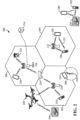
- FIG. 3 is a diagram illustrating a network architecture 300 with support for location services (LCS) according to some aspects of the disclosure.
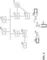
- FIG. 4 is a diagram illustrating architectural support for location services using a service-based interface representation of the network 300 according to some aspects of the disclosure.
- This network architecture 300 may be implemented using the wireless network illustrated and described in relation to FIGs. 1 and 2 .
- a UE 302 can access a core network (CN) 304 via a next generation (NG)-RAN 306.
- the core network 304 may be the core network 102
- the NG-RAN 306 may be the RAN 104.
- the NG-RAN 306 consists of gNBs and/or eNBs that communicate with the core network 304.
- the core network 304 includes various network functions and entities, for example, a location management function (LMF) 308, an access and mobility management function (AMF) 305, a unified data management (UDM) 310, a gateway mobile location center (GMLC) 312, and a location retrieval function (LRF) 316.
- LMF location management function
- AMF access and mobility management function
- UDM unified data management
- GMLC gateway mobile location center
- LRF location retrieval function
- the GMLC may have a direct interface with the LMF and can communicate directly with it
- the AMF may perform a simple forwarding function between the LMF and NG-RAN or UE.
- the core network 304 may support LCS using various positioning mechanism, for example, uplink and downlink cell coverage based positioning methods, an observed time difference of arrival (OTDOA) positioning method, an Assisted Global Navigation Satellite System (A-GNSS) based positioning method, an uplink-time difference of arrival (UTDOA) positioning method, etc.
- the core network 304 may support a ranging based positioning method, for example, in vehicle-to-vehicle (V2V) or vehicle-to-everything (V2X) applications.
- V2V vehicle-to-vehicle
- V2X vehicle-to-everything
- the measured distances can be combined with other positioning methods, e.g., satellite-based positions, to refine or improve UE position estimation.
- Ranging based V2X positioning can improve the accuracy of vehicle location determination to the order of centimeters or better.
- ranging signals transmitted by UEs can be concentrated in a short period of time to achieve highly accurate ranging measurements.
- the AMF 305 can provide various functions, for example, registration management, connection management, mobility management, access authentication/authorization, location services management, transport for location services messages between UE and LMF as well as between NG-RAN and LMF.
- the AMF is an example of a core network node.
- the LMF 308 can provide various functions, for example, receiving ranging information from the UEs, determining UEs' locations, obtaining downlink location measurements or a location estimate from the UE, obtaining uplink location measurements from the NG-RAN 306, and/or obtaining non-UE associated assistance data from the NG-RAN 306, etc.
- the UDM 310 provides various functions, for example, user identification handling (e.g., storage and management of SUPI (Subscriber Permanent Identifier) for each subscriber), access authorization based on subscription data, UE's serving network function registration management, and subscription management.
- user identification handling e.g., storage and management of SUPI (Subscriber Permanent Identifier) for each subscriber
- access authorization based on subscription data
- subscription management for example, user identification handling (e.g., storage and management of SUPI (Subscriber Permanent Identifier) for each subscriber), access authorization based on subscription data, UE's serving network function registration management, and subscription management.
- SUPI Subscriber Permanent Identifier
- the GMLC 312 provides a service interface to a location service (LCS) client 314.
- the LRF 316 retrieves location information for users that have initiated an emergency session.
- a group of UEs can participate in a ranging operation with respective allocated radio resources.
- UE1 may transmit a ranging signal 330 using first radio resources (Rsrc1) and a first Zadoff-Chu (ZC) sequence (ZC-seq1).
- UE2 may transmit a ranging signal 332 using second radio resources (Rsrc2) and a second ZC sequence (ZC-seq2).
- UE3 may transmit a ranging signal 334 using third radio resources (Rsrc3) and a third ZC sequence (ZC-seq3).
- each UE measures the ranging signal received from other UEs.
- the radio resources may be time-frequency resources scheduled by a scheduling entity.
- UE1 can determine the time of arrival (TOA) for this measurement (denoted as TOA12). This result may be stored in a result vector (TOA12, Rsrc2, ZC-seq2). Similarly, if UE1 receives the ranging signal 334 from UE3 sent using Rsrc3 and ZC-seq3, UE1 can determine the corresponding TOA for this measurement (denoted as TOA13). This result may be stored as a result vector (TOA13, Rsrc3, ZC-seq3).
- UE2 can measure the ranging signal 330 of UE1 and ranging signal 334 of UE3, and store the measurements in result vectors (TOA21, Rsc1, ZC-seq1) and (TOA23, Rsrc3, ZC-seq3).
- UE3 can perform similar measurements and obtain the result vectors (TOA31, Rscl, ZC-seq1); (TOA32, Rsrc2, ZC-seq2).
- Each UE reports its result vectors in a certain radio resource based ranging report to a RAN node (e.g., gNB).
- the RAN node may convert the radio resource based ranging report to an Internal ID based ranging report that is described in more detail below in relation to FIGs. 7-10 .
- ranging results are indexed or identified by the radio resources used to perform the corresponding ranging operations.
- ranging results are indexed or identified by the Internal IDs of the UEs.
- the RAN node can find: [Rsrc1, ZC-seql] (ToA12, Rsrc2, ZC-seq2); (ToA13, Rsrc3, ZC-seq3).
- the RAN node knows that [Rsrc1, ZC-seq1] corresponds to Internal ID1 that is assigned to UE1, (Rsrc2, ZC-seq2) corresponds to Internal ID2 that is assigned to UE2, and (Rsrc3, ZC-seq3) corresponds to Internal ID3 that is assigned to UE3.
- the RAN node can make these associations based on previous or predetermined radio resource allocation and an Internal ID allocation procedure.
- the RAN node can convert UEl's report to an Internal ID based ranging report that includes: [Internal ID1], (TOA12, Internal ID2), (TOA13, Internal ID3). Similarly, the RAN node can convert reports from UE2 and UE3. As a result, UE2's Internal ID based ranging report includes: [Internal ID2], (TOA21, Internal ID1), (TOA23, Internal ID3). Similarly, UE3's Internal ID based ranging report includes: [Internal ID3], (TOA31, Internal ID1), (TOA32, Internal ID2). After the conversion, the RAN node can report these Internal ID based ranging reports to the LMF, either individually or aggregated. The LMF can perform location calculation based on the ranging reports from all the UE1, UE2, and UE3. An exemplary location calculation includes taking all the reported TOA values and calculating the relevant round-trip time (RTT) value to determine the range between UEs.
- RTT round-trip
- the clock offset T off may be a few microseconds ( ⁇ s) and can be accommodated by the TOA range, for example, between -4000 nanoseconds (ns) and 4000 ns.
- the round-trip time (RTT) is 2 d/c.
- the network may report the RTT in nanoseconds. Because the network knows all the assigned ranging signaling resources for each of the UE, the network can estimate the RTT and therefore the distance between the UEs. When the RTT is combined with the known positions of some UEs or reference nodes, the network can determine the positions of all the UEs .
- the ranging report may include additional information, for example, UE's GNSS location information, antenna location, vehicle speed and/or direction, radio characteristics, etc.
- additional information for example, UE's GNSS location information, antenna location, vehicle speed and/or direction, radio characteristics, etc.
- the LMF can determine the results of the ranging calculation based on Internal IDs, and then convert the results to External ID based results.
- the Internal ID can use a small number range, e.g., 32 bits, relative to the External ID because the AMF may use the tracking area and/or RAN node ID to identify the results.
- the External ID on the other hand may need to have a much larger number range, e.g., 128 bits, because the network needs to identify a UE uniquely regardless of the UE's association.
- an Internal ID based report may have these data: [Internal ID1, Location 1], [Internal ID2, Location 2], and [Internal ID3, Location3].
- the LMF Based on stored information, the LMF knows that Internal ID1 corresponds to External ID1, Internal ID2 corresponds to External ID2, and Internal ID3 corresponds to External ID3. Therefore, the LMF can convert the results to [External ID1, Location 1], [External ID2, Location 2], [External ID3, Location 3].
- the LMF can send the location results back to the RAN to be delivered either directly to each individual UE or broadcasted to all UEs within the RAN node's coverage area. In some examples, the LMF can cause the RAN to use multimedia broadcast multicast services (MBMS) to broadcast the results.
- MBMS multimedia broadcast multicast services
- the External ID may be allocated by the AMF to hide the UE's permanent ID so that the LMF does not need to know the UE's permanent ID.
- the LMF may cause the RAN to transmit the location result in broadcast/multicast, the External ID may be used to indicate the UE in those announcements while not revealing the UE's true long-term ID (e.g., permanent ID) to improve privacy.
- the External ID may not be needed if obscuring the UE's ID is not a concern or needed.
- the UE's permanent ID may be used to identify the UE in the results that may be transmitted by the RAN using broadcast or unicast
- the LMF may allocate the Internal ID for internal use between the RAN and LMF.
- the RAN may use the Internal ID to perform radio resources allocation; therefore the LMF does not need to know the RAT details for the ranging operations, e.g., radio resources index, ZC sequence mapping to the UE, etc.
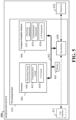
- FIG. 5 is a block diagram illustrating an example of a hardware implementation for a scheduling entity 400 employing a processing system 414.
- the scheduling entity 400 may be a user equipment (UE) as illustrated in any one or more of FIGs. 1 , 2 , and/or 3.
- the scheduling entity 400 may be a base station or network node as illustrated in any one or more of FIGs. 1 , 2 , and/or 3.
- the scheduling entity 400 may be implemented with a processing system 414 that includes one or more processors 404.
- processors 404 include microprocessors, microcontrollers, digital signal processors (DSPs), field programmable gate arrays (FPGAs), programmable logic devices (PLDs), state machines, gated logic, discrete hardware circuits, and other suitable hardware configured to perform the various functionality described throughout this disclosure.
- DSPs digital signal processors
- FPGAs field programmable gate arrays
- PLDs programmable logic devices
- state machines gated logic, discrete hardware circuits, and other suitable hardware configured to perform the various functionality described throughout this disclosure.
- the scheduling entity 400 may be configured to perform any one or more of the functions described herein. That is, the processor 404, as utilized in a scheduling entity 400, may be used to implement any one or more of the processes and procedures described below and illustrated in FIGs. 7-13 .
- the processing system 414 may be implemented with a bus architecture, represented generally by the bus 402.
- the bus 402 may include any number of interconnecting buses and bridges depending on the specific application of the processing system 414 and the overall design constraints.
- the bus 402 communicatively couples together various circuits including one or more processors (represented generally by the processor 404), a memory 405, and computer-readable media (represented generally by the computer-readable medium 406).
- the bus 402 may also link various other circuits such as timing sources, peripherals, voltage regulators, and power management circuits, which are well known in the art, and therefore, will not be described any further.
- a bus interface 408 provides an interface between the bus 402 and a transceiver 410.
- the transceiver 410 provides a communication interface or means for communicating with various other apparatus over a transmission medium.
- a user interface 412 e.g., keypad, display, speaker, microphone, joystick
- a user interface 412 is optional, and may be omitted in some examples, such as a base station.
- the processor 404 may include circuitry configured to implement one or more of the functions described below in relation to FIGs. 7-13 .
- the processor 404 may include a processing circuit 440, a communication circuit 442, and location service (LCS) circuit 444.
- the processing circuit 440 may be configured to perform various data processing and logic functions that may be used in wireless communication described herein.
- the communication circuit 442 may be configured to perform various communication processes and functions described herein.
- the LCS circuit 444 may perform various location services and ranging operations described herein.
- the processor 404 is responsible for managing the bus 402 and general processing, including the execution of software stored on the computer-readable medium 406.
- the software when executed by the processor 404, causes the processing system 414 to perform the various functions described below for any particular apparatus.
- the computer-readable medium 406 and the memory 405 may also be used for storing data that is manipulated by the processor 404 when executing software.
- One or more processors 404 in the processing system may execute software.
- Software shall be construed broadly to mean instructions, instruction sets, code, code segments, program code, programs, subprograms, software modules, applications, software applications, software packages, routines, subroutines, objects, executables, threads of execution, procedures, functions, etc., whether referred to as software, firmware, middleware, microcode, hardware description language, or otherwise.
- the software may reside on a computer-readable medium 406.
- the computer-readable medium 406 may be a non-transitory computer-readable medium.
- a non-transitory computer-readable medium includes, by way of example, a magnetic storage device (e.g., hard disk, floppy disk, magnetic strip), an optical disk (e.g., a compact disc (CD) or a digital versatile disc (DVD)), a smart card, a flash memory device (e.g., a card, a stick, or a key drive), a random access memory (RAM), a read-only memory (ROM), a programmable ROM (PROM), an erasable PROM (EPROM), an electrically erasable PROM (EEPROM), a register, a removable disk, and any other suitable medium for storing software and/or instructions that may be accessed and read by a computer.
- a magnetic storage device e.g., hard disk, floppy disk, magnetic strip
- an optical disk e.g., a compact disc (CD) or a digital versatile disc (DVD)
- a smart card e.g., a flash memory device (e.g
- the computer-readable medium 406 may reside in the processing system 414, external to the processing system 414, or distributed across multiple entities including the processing system 414.
- the computer-readable medium 406 may be embodied in a computer program product.
- a computer program product may include a computer-readable medium in packaging materials.
- the computer-readable storage medium 406 may include software configured to implement one or more of the functions described in relation to FIGs. 7-13 .
- the software may include processing instructions 452, communication instructions 454, and location service (LCS) instructions 456.
- the processing instructions 452 may configure the processor 404 to perform various data processing and logic functions that may be used in wireless communication described herein.
- the communication instructions 454 may configure the processor 404 to perform various communication processes and functions described herein.
- the LCS instructions 456 may configure the processor 404 to perform various location services and ranging operations described herein.
- FIG. 6 is a conceptual diagram illustrating an example of a hardware implementation for an exemplary scheduled entity 500 employing a processing system 514.
- an element, or any portion of an element, or any combination of elements may be implemented with a processing system 514 that includes one or more processors 504.
- the scheduled entity 500 may be a user equipment (UE) as illustrated in any one or more of FIGs. 1 , 2 , and/or 3.
- UE user equipment
- the processing system 514 may be substantially the same as the processing system 414 illustrated in FIG. 5 , including a bus interface 508, a bus 502, memory 505, a processor 504, and a computer-readable medium 506.
- the scheduled entity 500 may include a user interface 512 and a transceiver 510 substantially similar to those described above in FIG. 5 . That is, the processor 504, as utilized in a scheduled entity 500, may be used to implement any one or more of the processes described and illustrated in FIGs. 7-13 .
- the processor 504 may include circuitry configured to implement one or more of the functions described in relation to FIGs. 7-13 .
- the processor 504 may include a processing circuit 540, a communication circuit 542, and location service (LCS) circuit 544.
- the processing circuit 540 may be configured to perform various data and signal processing and logic functions that may be used in wireless communication described herein.
- the communication circuit 542 may be configured to perform various communication processes and functions described herein.
- the LCS circuit 544 may perform various location services and ranging operations described herein.
- the computer-readable storage medium 506 may include software configured to implement one or more of the functions described in relation to FIGs. 7-13 .
- the software may include processing instructions 552, communication instructions 554, and location service (LCS) instructions 556.
- the processing instructions 552 may configure the processor 504 to perform various data processing and logic functions that may be used in wireless communication described herein.
- the communication instructions 554 may configure the processor 504 to perform various communication processes and functions described herein.
- the LCS instructions 556 may configure the processor 504 to perform various location services and ranging operations described herein.
- aspects of the present disclosure are directed to location service (LCS) support in a wireless communication system and, more particularly, LCS support for V2X ranging based positioning.
- V2X ranging based positioning involves a group of devices (e.g., UEs or vehicles) coordinated to achieve positioning using ranging signals. Identification, control, coordination, and support of V2X positioning is different from that of other LCS positioning methods, for example, due to ranging signal design and UE privacy requirements.
- the network may manage (e.g., schedule, allocate) radio resources for V2X ranging based positioning operation, but otherwise has limited involvement in the ranging operation between UEs.
- the network facilitates the selection of a V2X specific LCS server (e.g., LMF 308) based on, for example, network slicing or the like.
- a wireless communication network may be separated into a plurality of virtual service networks (VSNs), or network slices, which are separately configured to better suit the needs of different types of services.
- VSNs virtual service networks
- network slicing is a form of virtualization that allows multiple logical networks or services to run on top of a shared physical network infrastructure.
- Some wireless communication networks may be separated, e.g., according to mobile broadband, internet of things (IoT), V2X, and other services.
- a V2X slice may be defined in a network for providing V2X related ranging-based positioning functions.
- an access and mobility management function may bind a V2X specific LCS server (e.g., an LMF 308 of FIG. 3 ) based on a V2X slice ID.
- a UE can indicate its desire or support for V2X ranging based LCS using non-access stratum (NAS) signaling between the UE and core network nodes (e.g., AMF and LMF).
- NAS non-access stratum
- a radio access network e.g., NG-RAN 306, and in the following description may be referred as RAN
- RAN can assist in ranging ID mapping and resources allocation.
- External ID and Internal ID may be used to protect the privacy of a UE that participates in a ranging based location service session and isolate the radio specific resource management from a core network.
- a radio access network (RAN) node e.g., a base station or gNB
- the LMF may assist in ID management to facilitate V2X ranging privacy and RAT agnostic operation.
- the LMF can allocate the Internal ID for use by the RAN node to achieve RAT independence.
- the LMF can use an External ID to identify a UE in location results to provide privacy protection of the UE when causing the RAN to announce the results using broadcast or multicast.
- the RAN node can refine the radio resources allocation for ranging operation based on a known or estimated location of the UE. For example, based on the knowledge of the rough position of the UE, e.g., in a sector of the cell, to the RAN node can decide which resources pool the UE may use to avoid potential collision or improve on the reception.
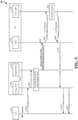
- FIG. 7 is a diagram illustrating a signaling process 600 of UE registration and selection of an LCS server in a wireless communication network according to some aspects of the disclosure.
- the signaling process 600 involves a UE 602, a RAN 604, an AMF 606, and an LMF 608.
- the AMF 606 and LMF 608 may be components of a core network (e.g., CN 304). These entities may be similar or the same to those described and illustrated in FIGs. 1-3 .
- the signaling process 600 may be carried out by any suitable apparatus or means for carrying out the functions or algorithm described below.
- the UE 602 may establish a radio control resource (RRC) connection with the RAN 604 (e.g., NG-RAN), for example, using a random access procedure.
- the UE may indicate its desire or request for a network slice (e.g., V2X slice) that supports V2X ranging based location service (LCS).
- a network slice e.g., V2X slice
- LCS V2X ranging based location service
- Such indication can be included in an RRC message and an NAS message 610 (e.g., registration request) for UE registration.
- the RAN 604 selects an AMF (e.g., selecting AMF 606 in block 611) that can support this V2X network slice (i.e., support V2X ranging based LCS).
- the RAN 604 may optionally prepare or allocate V2X ranging radio resources (e.g., in block 612) for the UE. Some examples of these radio resources are time-frequency resources, spatial resources, and coding sequences (e.g., Zadoff-Chu (ZC) sequence and the like).
- the RAN 604 forwards a UE register message 614 to the selected AMF.
- the register message 614 may optionally provide V2X ranging related information, for example, cell ID, cell size, frequencies, etc., encapsulated in a positioning protocol message (e.g., illustrated as NPPa (V2X ranging info)) destined for an LMF via the AMF.
- a positioning protocol message e.g., illustrated as NPPa (V2X ranging info)
- the RAN may send V2X ranging related information in a container Information Element (IE) in a NAS message (e.g., N2 message) towards the AMF.
- IE container Information Element
- the V2X ranging related information may contain an Internal ID proposed by the NG-RAN node (e.g., RAN 604) corresponding to the radio resources reserved for the UE.
- the AMF 606 selects (e.g., in block 616) an LMF (e.g., LMF 608) that can support V2X ranging based LCS.
- the AMF 606 may check (e.g., block 618) whether the UE has a subscription or authorization to use ranging based LCS. Then, the AMF transmits a request (e.g., Loc session init 620) to the LMF to start a ranging based location service session.
- the AMF may forward the V2X ranging related information, if available, encapsulated in a positioning protocol message (e.g., NPPa (V2X ranging info)).
- a positioning protocol message e.g., NPPa (V2X ranging info)
- the AMF may send the V2X ranging related information in a container IE as part of the interaction between the AMF and LMF.
- the AMF 606 may allocate and provide the LMF with an External ID for identifying the UE during the ranging based location service session
- the External ID can be used in a location result announcement for the UE over the air interface in the RAN. Because the location result may be seen by all other UEs in the RAN, using the External ID to identify the UE in the location result can hide the UE's permanent ID from other UEs and the LMF.
- the External ID may be replaced with the UE's permanent ID when the RAN communicates with the UE using a point-to-point (e.g., unicast) and/or secured communication.
- the network may use the UE's permanent ID to identify the UE in the location result when privacy is not a concern or needed.
- permanent ID are International Mobile Subscriber Identity (IMSI), Subscriber Permanent Identifier (SUPI), Subscription Concealed Identifier (SUCI), etc.
- IMSI International Mobile Subscriber Identity
- SUPI Subscriber Permanent Identifier
- SUCI Subscription Concealed Identifier
- the AMF 606 may change the UE's External ID periodically (e.g., every 5 minutes) or aperiodically to reduce the possibility that the UE could be tracked by other users in the network.
- the AMF 606 can maintain the External ID as long as the UE is registered with V2X ranging support.
- the AMF may remove or reassign the External ID when the UE deregisters or disables V2X ranging based LCS.
- the External ID can be carried within a UE context across AMFs, and can be updated based on AMF's decision.
- the UE may at least partially control the External ID that may be used to identify the UE.
- the UE may provide the network a key or certificate during registration for location service that may be used to determine or authenticate the External ID.
- the LMF 608 may allocate an Internal ID for identifying the UE during the ranging based location service session.
- the Internal ID is used in communication between the RAN 604 and the LMF 608 using a positioning protocol.
- a RAN node e.g., a base station or gNB
- the LMF can update or change the Internal ID after a predetermined period of time whether or not the UE remains in the RAN node's coverage.
- the Internal ID may change less or more frequently than the External ID.
- the LMF 608 may allocate the Internal ID when ranging based LCS is activated for the UE.
- the LMF 608 can update the Internal ID when the UE changes its RAN node or RAN area. For example, the LMF 608 can allocate a new Internal ID when the UE communicates with a new RAN node (e.g., gNB). The LMF may deallocate the Internal ID when the UE moves out of the area of a RAN or to another radio access technology (RAT).
- RAT radio access technology
- the LMF 608 transmits an acknowledgment message (e.g., Loc session init ACK 621) to the AMF, for example, including the Internal ID and/or External ID.
- the LMF may encapsulate the External ID in a positioning protocol message (e.g., NPP (ID-Ext)) destined for the UE.
- the External ID may be used in direct ranging report from the UEs and location result announcement to the UEs.
- the LMF may encapsulate the Internal ID in a positioning protocol message (e.g., NPPa (ID-Int.)) destined for the RAN.
- the AMF 606 forwards the LMF's message in an acknowledgment message (e.g., NAS Register ACK 622), for example including the NPP and NPPa that contain External ID and Internal ID, to the RAN 604. Then, the RAN forwards the NPP message containing the External ID to the UE.
- the RAN may allocate radio resources accordingly to the UE for ranging use, and associate the radio resources with the Internal ID indicated by the LMF.
- the RAN may send the radio resource allocation and NPP message that contains the External ID to the UE in a registration response (e.g., a non-access stratum (NAS) Register ACK 624) carried by an RRC message.
- the AMF may forward the NPP message that contains the External ID to the UE as a separate NAS message, instead of piggybacking on the registration response 624.
- FIG. 8 is a diagram illustrating a signaling process 700 of a ranging based location service in a wireless communication network according to some aspects of the disclosure.
- the signaling process 700 involves a UE 702, a RAN 704, an AMF 706, and an LMF 708.
- the AMF 706 and LMF 708 may be components of a core network (e.g., CN 304). These entities may be similar to those described and illustrated in FIGs. 1-3 . In one example, these network entities are the same as those illustrated in FIG. 7 .
- the signaling process 700 may be carried out by any suitable apparatus or means for carrying out the functions or algorithm described below.
- the UE 702 may be in an RRC connected mode with the RAN 704 and can report its ranging results to the RAN 704 (e.g., a NG-RAN node, gNB, eNB, base station) using an RRC connection.
- the UE may report the ranging results in an RRC based ranging report 710 that includes, for example, a list of time of arrival (TOA) data, sequence ID, and radio resource index.
- the ranging report 710 may be called a radio resource based ranging report
- the TOA data may include the measured TOA of a ranging signal sent by other UEs (e.g., UE1, UE2, UE3 in FIG.
- the radio resource index may indicate a subframe number and a symbol number. In one example, there may be 16 subframes with 14 symbols in each subframe. Because the RAN node knows the mapping between the Internal ID and radio resources allocated to the UE 702 for ranging operation, at block 712, the RAN node can convert the radio resource based ranging report to an Internal ID based report That is the ranging report can be identified by the Internal ID. For example, the Internal ID based report may contain a list of TOA data and corresponding Internal ID. While FIG.
- the RAN node and LMF may receive multiple ranging reports from different UEs in the same area covered by the RAN node.
- the RAN node 704 may aggregate multiple reports from different UEs and send them to the LMF together in one report message.
- the RAN node 704 transmits the Internal ID based report 714 to the LMF 708 via the AMF 706.
- the RAN can encapsulate the measurement results in a positioning protocol message (e.g., NPPa (measurement results)) destined for the LMF.
- AMF forwards the message to the LMF as a location determination request (e.g., Loc Request 716).
- the LMF can calculate, at block 717, the location results and send it back to the AMF in a location determination response (e.g., Loc Response 718).
- the AMF routes the location results to the RAN 704.
- the LMF can encapsulate the location results in a positioning protocol message (e.g., NPPa (location results)) destined for the RAN node.
- the AMF forwards the NPPa (location results) 720 to the RAN without knowing the contents of the location results.
- the RAN can send the location results 722 dedicated to a single UE or a group of UEs using a dedicated RRC message, cell broadcast, or single cell point-to-multipoint (SC-PTM) transmission.
- the LMF may cause the RAN to use multimedia broadcast multicast services (MBMS) 724 to send the results to a group of UEs within a group of cells including the RAN 704.
- MBMS multimedia broadcast multicast services
- the LMF can specify the cells that broadcast the results using an MB2 or xMB interface or the like to an MBMS system.
- the LMF may associate the location results with External IDs such that no other UEs can determine the association between the location results 722 and the target UE.
- FIG. 9 is a diagram illustrating a signaling process 800 of a ranging based location service in a wireless communication network according to some aspects of the disclosure.
- the signaling process 800 involves a UE 802, a RAN including a target RAN node 804 and a source RAN node 805, an AMF 806, and an LMF 808.
- the AMF 806 and LMF 808 may be components of a core network (e.g., CN 304). These entities may be similar to those described and illustrated in FIGs. 1-3 . In one example, these network entities are the same as those illustrated in FIGs. 7 and 8 .
- the signaling process 800 may be carried out by any suitable apparatus or means for carrying out the functions or algorithm described below.
- the UE 802 was in an RRC inactive mode, and it may have moved to a new coverage area, sector, or cell of a different RAN node (i.e., from a source RAN node to a target RAN node) within the same RAN area. Therefore, when the UE 802 transmits its ranging report 810 to the RAN, the ranging report may be received by a target RAN node 804 that is different from the original RAN node (i.e., a source RAN node 805) that started a ranging based location service session as described above in relation to FIG. 7 . In this case, the UE transitioned or switched from the source RAN to the target RAN.
- a target RAN node 804 that is different from the original RAN node (i.e., a source RAN node 805) that started a ranging based location service session as described above in relation to FIG. 7 .
- the UE transitioned or switched from the source RAN to the target RAN
- the RAN nodes may be base stations, eNBs, or gNBs.
- the target RAN node 804 can forward the ranging report 812 to the source RAN node 805 and include the target RAN node's own ID (e.g., cell ID) so that the LMF knows how to send the location results back to the target RAN node.
- the target RAN node's own ID e.g., cell ID
- the source RAN node 805 maps the ranging report to an Internal ID based ranging report, and transmits the report 814 to the AMF 806. Then, the AMF 806 forwards the reports 814 to the LMF 808.
- the RAN node may encapsulate the ranging report 814 in a positioning protocol message (e.g., NPPa (measurement results)) destined for the LMF.
- the AMF may forward the message to the LMF in a location determination request 814.
- the target RAN node 804 can obtain the Internal ID to radio resources mapping information from the source RAN node, and maps the ranging report to an Internal ID based ranging report.
- the LMF 808 can calculate, at block 815, the location of the UE and send the location results back to the UE via the AMF and RAN.
- the LMF 808 can transmit a location response 816 including the location results encapsulated in a positioning protocol message (e.g., as NPPa (location results)) destined for the RAN.
- the AMF forwards the results 818 to the RAN.
- the RAN sends the location results 820 dedicated to the UE 802 using wireless communication, the location results may be protected using an External ID like that described in relation to FIGs. 7 and 8 above, so that the UE's location cannot be tracked by other users that may receive the location results.
- the LMF 808 sends the location results back to the target RAN node 804, not the source RAN node 805.
- the target RAN node 804 may allocate new radio resources 822 to the UE 802 so that the UE can perform ranging operation in an area covered by the target RAN node.
- the target RAN node can fetch the UE context from source RAN node when it receives the ranging report in 810. This way, the target RAN node can perform the conversion of the ranging report to an Internal ID based report and send it directly to the AMF.
- the operations performed by the AMF 806 and LMF 808 are substantially similar or identical to those described above in relation to FIG. 8 .
- the LMF instead of forwarding the location results to the target RAN node, the LMF can cause the RAN to broadcast or multicast the location results, for example, using MBMS broadcast or the like.
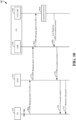
- FIG. 10 is a diagram illustrating a signaling process 900 of a ranging based location service in a wireless communication network according to some aspects of the disclosure.
- the signaling process 900 involves a UE 902, a RAN 904, an AMF 906, and an LMF 908. These entities may be similar to those described and illustrated in FIGs. 1-3 . In one example, these network entities are the same as those illustrated in FIGs. 7-9 .
- the signaling process 900 may be carried out by any suitable apparatus or means for carrying out the functions or algorithm described below.
- the UE 902 is in an RRC idle mode (i.e., no active RRC connection), and the RAN 904 has no UE context for the UE 902 yet. Therefore, the UE may identify its ranging report with the radio resources used and its External ID that is assigned by the AMF 906.
- the UE 902 transmits a ranging report 910 with its External ID encapsulated in a NAS message to the RAN 904.
- the UE may encapsulate and transmit the ranging report 910 in a positioning protocol message (e.g., NPP (Ranging report, External-ID)), which is indicated to be routed to the LMF 908.
- NPP Navigation report, External-ID
- the RAN 904 routes the NPP message 912 to the AMF 906 that further routes the NPP message 914 to the LMF 908.
- the LMF 908 can determine the UE's location based on the UE's ranging report.
- the UE can use its External ID, cell ID, and/or tracking area identity (TAI) to derive the resources for ranging operation.
- TAI tracking area identity
- the UE may apply a hash function over the External ID, Cell ID or TAI, its own antenna ID or any combination thereof, and use the output of the hash function to select the parameters (e.g., ZC Sequence ID and a resource Index) for ranging operation.
- the UE may select the radio resources within a resource pool reserved for IDLE mode UE ranging operation by the network.
- the RAN may announce the resource pool in a system information block (SIB), or the base station (e.g., gNB) may configure the resource pool when the UE was in a CONNECTED mode.
- the radio resources may be configured via a provisioning mechanism (e.g., Open Mobile Alliance (OMA) Device Management (DM), or UE Policy configuration), or preconfigured on the UE or UMTS Subscriber Identify Module.
- OMA Open Mobile Alliance
- DM Device Management
- UE Policy configuration e.g., UE Policy configuration
- the LMF can calculate the UE's location results at block 915.
- the LMF may send the location results to the AMF in a location response 916.
- the location results may be encapsulated in a positioning protocol message (e.g., NPPa (Location results)) destined for the RAN.
- the AMF can forward the results 918 to multiple RAN nodes (e.g., a source RAN node and a target RAN node).
- the RAN can send the location results 920 dedicated to the UE using wireless communication.
- the location results may be indexed using an External ID like that described in relation to FIGs.
- the RAN may broadcast the location results to the UE using MBMS or the like.
- the UE 902 may have moved to a new area covered by a target RAN node.
- the target RAN node may allocate new radio resources 822 to the UE so that the UE can perform ranging operation in the area covered by the new RAN node.
- FIG. 11 is a flow chart illustrating a process 1000 for allocating ranging radio resources in accordance with some aspects of the present disclosure.
- the process 1000 may be performed by the RAN described above in relation to FIGs 7-10 .
- the RAN can progressively refine the radio resources allocated to the UE for ranging based location service.
- the RAN can first allocate radio resources to UEs using a resource pool that is used for ranging by all UEs in a cell or RAN area.
- the RAN determines the UE location results based on UE's ranging report.
- the RAN can improve radio resources management by allocating ranging resources that are specific or exclusive to a smaller area (e.g., a sector or zone within the cell or RAN coverage area). By allocating resources for a smaller area, it is possible to reuse resources in different areas of a cell or RAN area.
- the LMF can inform the RAN regarding the UE's location as part of the Internal ID operation.
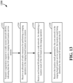
- FIG. 12 is a flow chart illustrating a process 1100 of a ranging based location service session in accordance with some aspects of the present disclosure. As described below, some or all illustrated features may be omitted in a particular implementation within the scope of the present disclosure, and some illustrated features may not be required for implementation of all embodiments.
- the process 1100 may be carried out by the scheduling entity 400 illustrated in FIG. 5 . In some examples, the process 1100 may be carried out by any suitable apparatus or means for carrying out the functions or algorithm described below.
- the process 1100 is carried out by one or more nodes of a radio access network (RAN) and/or a core network.
- RAN radio access network
- a RAN node may use a communication circuit 442/transceiver 410 (see FIG. 4 ) to receive a registration request from a UE.
- the registration request indicates that the UE can support a ranging based location service session.
- a RAN node 306 e.g., gNB
- the connection request may send a registration message included in a non-access stratum (NAS) message destined for a core network node, for example, an access and mobility management function (AMF) 305.
- NAS non-access stratum
- AMF access and mobility management function
- a location management function (LMF) of a core network can be selected to determine the location of the UE using various positioning methods assisted by ranging data provided by the UE.
- LMF location management function
- the RAN node may use an LCS circuit 444 (see FIG. 4 ) to allocate radio resources to the UE for performing a ranging operation.
- the ranging operation may involve measuring and/or determining the distances between pairs of UEs among a plurality of UEs using ranging signals transmitted by the UEs.
- radio resources are time-frequency resources and sequences (e.g., Zadoff-Chu (ZC) sequence) for transmitting ranging signals.
- ZC Zadoff-Chu
- the RAN node may use the communication circuit 442/transceiver 410 to transmit or forward a message based on the registration request to the AMF configured to select an LMF that supports the ranging based location service session.
- the AMF 305 may select the LMF 308 that is configured to determine a location result of the UE based on the ranging operation.
- the LMF may determine the location of the UE using ranging reports received from different UEs in an area served by the same RAN node.
- the RAN node may provide ranging information to the LMF in a positioning protocol message (e.g., NPPa (V2X ranging info)) destined for the LMF.
- a positioning protocol message e.g., NPPa (V2X ranging info)
- the RAN node may use the LCS circuit 444 to provide the UE with an External ID determined by the AMF for identifying a location result of the UE transmitted in the RAN.
- the location result is determined by the LMF based on the results of the ranging operation from one or more UEs.
- Using the External ID in association with the location result may protect the identity of the UE from other UEs.
- the External ID may be updated from time to time or periodically by the AMF to reduce the chance that the UE could be tracked beyond short periods of time by other users.
- the RAN node may use the communication circuit 442/transceiver 410 to receive an Internal ID for identifying information, associated with the UE, between the RAN node and the LMF during the ranging based location service session. Similar to the Internal ID described in relation to FIGs. 7-10 , the LMF can allocate the Internal ID for use by the RAN node to achieve RAT independence.
- the RAN node may use the LCS circuit 444 to allocate radio resources, associated with the internal ID, to the UE for performing the ranging operation involving a plurality of devices including the UE.
- the RAN node may use the LCS circuit 444 to inform the UE of the allocated radio resources for the ranging operation.
- the RAN node may use the communication circuit 442/transceiver 410 to transmit a message to UE, the message indicating the allocated radio resources for the ranging operation.
- FIG. 13 is a flow chart illustrating a process 1200 of a ranging based location service session in accordance with some aspects of the present disclosure. As described below, some or all illustrated features may be omitted in a particular implementation within the scope of the present disclosure, and some illustrated features may not be required for implementation of all embodiments.
- the process 1200 may be carried out by the scheduled entity 500 illustrated in FIG. 6 .
- the process 1200 may be carried out by any suitable apparatus or means for carrying out the functions or algorithm described below.
- the process 1200 is carried out by the UE described in relation to FIGs. 1-4 and 7-10 .
- a UE uses a communication circuit 542/transceiver 510 (see FIG. 5 ) to transmit a registration request to a radio access network (RAN), indicating that the UE supports a ranging based location service session.
- the registration request may include a registration message 610 in a NAS message destined for an AMF, similar to that described in FIG. 7 .
- the UE may use the communication circuit 542/transceiver 510 to receive an allocation of radio resources for performing a ranging operation.
- the RAN node e.g., a base station or gNB
- the UE may use the communication circuit 542/transceiver 510 to receive an External ID allocated by a core network, for example, a mobility management function (AMF).
- the External ID identifies a location result of the UE determined by a LMF based on measurement results of the ranging operation.
- the UE may use the communication circuit 542/transceiver 510 to receive the location result generated by the core network, for example, a location management function (LMF) for the ranging based location service session.
- LMF location management function
- the UE may use an LCS circuit 444 to identify its location result using its External ID.
- the LMF allocates and transmits the External ID to the UE via the AMF and RAN in a positioning protocol message (e.g., NPPa (Location results)) destined for the UE.
- the External ID can protect the identity of the UE when its location result is transmitted in the RAN, for example, as a broadcast message that could be received by other users as well.
- the apparatus 400 and/or 500 for wireless communication includes various means configured to perform the functions and processes described in relation to FIGs. 1-13 .
- the aforementioned means may be a circuit or any apparatus configured to perform the functions recited by the aforementioned means.
- a RAN node includes a communication circuit 442/transceiver 410 that provides the means for receiving a registration request from a UE, indicating that the UE supports a ranging based location service session.
- the communication circuit 442/transceiver 410 further provides the means for receiving an internal ID for identifying information associated with the UE in communication between the first RAN node and a core network during the ranging based location service session.
- the RAN node includes an LCS circuit 444 that provides the means for allocating radio resources to the UE for performing a ranging operation in the ranging based location service session involving a plurality of devices including the UE, and associating the radio resources with the internal ID.
- the LCS circuit 444 may provide the means for providing a registration response to the UE, indicating the allocated radio resources for performing the ranging operation.
- a UE includes a communication circuit 542/transceiver 510 that provides the means for transmitting a registration request to a RAN, indicating that the UE supports a ranging based location service session.
- the communication circuit 542/transceiver 510 may provide the means for receiving, from the RAN, an allocation of radio resources for performing a ranging operation in the ranging based location service session.
- the LCS circuit 544 may provide the means for performing the ranging operation to generate location results.
- the communication circuit 542/transceiver 510 may provide the means for receiving an external identifier (ID) from the RAN, the external ID allocated by a core network for identifying a location result of the UE based on the ranging operation.
- ID external identifier
- the communication circuit 542/transceiver 510 may provide the means for receiving the location result generated by the core network in the ranging based location service session, the location result being identified by the external ID associated with the UE.
- the UE may use the LCS circuit 544 as the means for identifying the location result using the external ID.
- circuitry included in the processor 404/504 is merely provided as an example, and other means for carrying out the described functions may be included within various aspects of the present disclosure, including but not limited to the instructions stored in the computer-readable storage medium 406/506, or any other suitable apparatus or means described in any one of the FIGs. 1-10 , and utilizing, for example, the processes and/or algorithms described herein in relation to FIGs. 7-13 .
- various aspects may be implemented within other systems defined by 3GPP, such as Long-Term Evolution (LTE), the Evolved Packet System (EPS), the Universal Mobile Telecommunication System (UMTS), and/or the Global System for Mobile (GSM).
- LTE Long-Term Evolution
- EPS Evolved Packet System
- UMTS Universal Mobile Telecommunication System
- GSM Global System for Mobile
- 3GPP2 3rd Generation Partnership Project 2
- EV-DO Evolution-Data Optimized
- Other examples may be implemented within systems employing IEEE 802.11 (Wi-Fi), IEEE 802.16 (WiMAX), IEEE 802.20, Ultra-Wideband (UWB), Bluetooth, and/or other suitable systems.
- Wi-Fi IEEE 802.11
- WiMAX IEEE 802.16
- UWB Ultra-Wideband
- Bluetooth and/or other suitable systems.
- the actual telecommunication standard, network architecture, and/or communication standard employed will depend on the specific application and the overall design constraints imposed on the system.
- the word "exemplary” is used to mean “serving as an example, instance, or illustration.” Any implementation or aspect described herein as “exemplary” is not necessarily to be construed as preferred or advantageous over other aspects of the disclosure. Likewise, the term “aspects” does not require that all aspects of the disclosure include the discussed feature, advantage or mode of operation.
- the term “coupled” is used herein to refer to the direct or indirect coupling between two objects. For example, if object A physically touches object B, and object B touches object C, then objects A and C may still be considered coupled to one another-even if they do not directly physically touch each other. For instance, a first object may be coupled to a second object even though the first object is never directly physically in contact with the second object.
- circuit and circuitry are used broadly, and intended to include both hardware implementations of electrical devices and conductors that, when connected and configured, enable the performance of the functions described in the present disclosure, without limitation as to the type of electronic circuits, as well as software implementations of information and instructions that, when executed by a processor, enable the performance of the functions described in the present disclosure.
- FIGs. 1-12 One or more of the components, steps, features and/or functions illustrated in FIGs. 1-12 may be rearranged and/or combined into a single component, step, feature or function or embodied in several components, steps, or functions. Additional elements, components, steps, and/or functions may also be added without departing from novel features disclosed herein.
- the apparatus, devices, and/or components illustrated in FIGs. 1-12 may be configured to perform one or more of the methods, features, or steps described herein.
- the novel algorithms described herein may also be efficiently implemented in software and/or embedded in hardware.
Landscapes
- Engineering & Computer Science (AREA)
- Computer Networks & Wireless Communication (AREA)
- Signal Processing (AREA)
- Physics & Mathematics (AREA)
- General Physics & Mathematics (AREA)
- Radar, Positioning & Navigation (AREA)
- Remote Sensing (AREA)
- Mobile Radio Communication Systems (AREA)
Claims (11)
- Ein Verfahren zum Vorsehen eines Standortdienstes an einem Funkzugriffsnetzwerk bzw. RAN (RAN = radio access network), das einen ersten RAN-Knoten in Drahtloskommunikation aufweist, wobei das Verfahren durch den ersten RAN-Knoten durchgeführt wird und Folgendes aufweist:Empfangen (1102) einer Anfrage von einer Nutzereinrichtung bzw. UE (UE = user equipment), die anzeigt, dass die UE eine entfernungsmessungsbasierte Standortdienstsitzung unterstützt;Weiterleiten (1106) der Anfrage an eine Kernnetzwerkeinheit in dem Kernnetzwerk, wobei die Kernnetzwerkeinheit konfiguriert ist zum Auswählen einer Standortverwaltungsfunktion bzw. LMF (LMF = location management function) in dem Kernnetzwerk, die die entfernungsmessungsbasierte Standortdienstsitzung unterstützt;Senden (1108) einer Nachricht an die UE, die einen externen Identifikator bzw. eine externe ID (ID = identifier) anzeigt, der bzw. die durch die Kernnetzwerkeinheit zugeteilt ist zum Identifizieren eines Standortergebnisses der UE;Empfangen (1110) eines internen Identifikators bzw. einer internen ID zum Identifizieren von Information, die mit der UE assoziiert ist, zwischen dem ersten RAN-Knoten und einem Kernnetzwerk während der entfernungsmessungsbasierten Standortdienstsitzung;Zuteilen (1112) von Funkressourcen, die mit der internen ID assoziiert sind, zu der UE zum Durchführen einer Entfernungsmessungsoperation in der entfernungsmessungsbasierten Standortdienstsitzung, die eine Vielzahl von Einrichtungen einschließlich der UE involviert, wobei das Standortergebnis der UE durch die LMF basierend auf der Entfernungsmessungsoperation bestimmt wird;Senden (1114) einer Antwort an die UE, die Funkressourcen anzeigt, die zum Durchführen der Entfernungsmessungsoperation zugeteilt sind;Empfangen, von der UE, eines ressourcenbasierten Entfernungsmessungsberichts, der durch die Entfernungsmessungsoperation generiert wird, wobei der ressourcenbasierte Entfernungsmessungsbericht Entfernungsmessungsergebnisse aufweist, die durch Funkressourcen, die der UE zugeteilt sind, indexiert bzw. identifiziert sind;Wandeln des ressourcenbasierten Entfernungsmessungsberichts in einen auf internen IDs basierenden Entfernungsmessungsbericht, wobei der auf internen IDs basierende Entfernungsmessungsbericht die Entfernungsmessungsergebnisse aufweist, die durch interne IDs, die mit der UE assoziiert sind, indexiert bzw. identifiziert sind; undSenden des auf internen IDs basierenden Entfernungsmessungsberichts an die LMF.
- Verfahren nach Anspruch 1, das weiter Folgendes aufweist:Empfangen des Standortergebnisses von der LMF; undSenden, an die UE, des Standortergebnisses, das durch die externe ID identifiziert wird.
- Verfahren nach Anspruch 1, das weiter Folgendes aufweist:
Empfangen einer Aktualisierung interner IDs von dem Kernnetzwerk ansprechend darauf, dass die UE von dem ersten RAN-Knoten zu einem zweiten RAN-Knoten des RAN übergeht. - Verfahren nach Anspruch 1, wobei das Zuteilen von Funkressourcen Folgendes aufweist:Zuteilen erster Funkressourcen zu der UE zum Durchführen der Entfernungsmessungsoperation in einem ersten Bereich; undZuteilen, basierend auf einem Standortergebnis, das unter Nutzung der ersten Funkressourcen bestimmt wird, von zweiten Funkressourcen zu der UE zum Durchführen der Entfernungsmessungsoperation in einem zweiten Bereich, der kleiner als der erste Bereich ist.
- Ein Verfahren, das durch eine Nutzereinrichtung bzw. UE (UE = user equipment) in einem Kommunikationsnetzwerk durchgeführt wird, das Folgendes aufweist:Senden (1202) einer Anfrage an einen ersten Funkzugriffsnetzwerkknoten bzw. RAN-Knoten (RAN = radio access network) eines Funkzugriffsnetzwerks bzw. RAN, die anzeigt, dass die UE eine entfernungsmessungsbasierte Standortdienstsitzung unterstützt;Empfangen (1204), von dem ersten RAN-Knoten, einer Zuteilung von Funkressourcen zum Durchführen einer Entfernungsmessungsoperation in der entfernungsmessungsbasierten Standortdienstsitzung;Empfangen (1206) eines externen Identifikators bzw. einer externen ID (ID = identifier) von dem ersten RAN-Knoten, wobei die externe ID durch eine Kernnetzwerkeinheit zugeteilt ist, die konfiguriert ist zum Auswählen einer Standortverwaltungseinheit bzw. LMF (LMF = location management function) in dem Kernnetzwerk, das die entfernungsmessungsbasierte Standortdienstsitzung unterstützt, und zwar zum Identifizieren eines Standortergebnisses der UE, wobei das Standortergebnis durch die LMF basierend auf der Entfernungsmessungsoperation bestimmt wird; undEmpfangen (1208) des Standortergebnisses, das durch das Kernnetzwerk in der entfernungsmessungsbasierten Standortdienstsitzung generiert wird, wobei das Standortergebnis durch die externe ID identifiziert wird, die mit der UE assoziiert ist.
- Verfahren nach Anspruch 5, das weiter Folgendes aufweist:Durchführen der Entfernungsmessungsoperation zum Generieren eines Entfernungsmessungsberichts; undSenden des Entfernungsmessungsberichts an den ersten RAN-Knoten, wobei der Entfernungsmessungsbericht wenigstens Ankunftszeit-Daten bzw. TOA-Daten (TOA = time of arrival), eine Sequenz-ID und einen Funkressourcenindex, der mit der Entfernungsmessungsoperation assoziiert ist, aufweist.
- Verfahren nach Anspruch 6, das weiter Verkapseln des Entfernungsmessungsberichts in eine Positionsbestimmungsprotokollnachricht aufweist, die für die LMF bestimmt ist.
- Verfahren nach Anspruch 6, das weiter Verkapseln des Entfernungsmessungsberichts und der externen ID in eine Positionsbestimmungsprotokollnachricht aufweist.
- Verfahren nach Anspruch 6, wobei das Empfangen des Standortergebnisses Folgendes aufweist:Empfangen einer dedizierten Nachricht an die UE, die das Standortergebnis aufweist; oderEmpfangen einer Broadcast-Nachricht, die das Standortergebnis aufweist.
- Ein erster Funkzugriffsnetzwerk- bzw. RAN-Knoten (RAN = radio access network) eines Funkzugriffsnetzwerks, der Folgendes aufweist:eine Kommunikationsschnittstelle, die für Drahtloskommunikation konfiguriert ist;einen Speicher; undeinen Prozessor, der betriebsmäßig an die Kommunikationsschnittstelle und den Speicher gekoppelt ist,wobei der Prozessor und der Speicher konfiguriert sind zum:Empfangen einer Anfrage von einer Nutzereinrichtung bzw. UE (UE = user erquipment), die anzeigt, dass die UE eine entfernungsmessungsbasierte Standortdienstsitzung unterstützt;Weiterleiten der Anfrage an eine Kernnetzwerkeinheit in einem Kernnetzwerk, wobei die Kernnetzwerkeinheit konfiguriert ist zum Auswählen einer Standortverwaltungsfunktion bzw. LMF (LMF = location management function) in dem Kernnetzwerk, das die entfernungsmessungsbasierte Standortdienstsitzung unterstützt;Senden einer Nachricht an die UE, die einen externen Identifikator bzw. eine externe ID (ID = identifier) anzeigt, der bzw. die durch die Kernnetzwerkeinheit zugeteilt ist zum Identifizieren eines Standortergebnisses der UE;Empfangen eines internen Identifikators bzw. einer internen ID zum Identifizieren von Information, die mit der UE assoziiert ist, zwischen dem ersten RAN-Knoten und einem Kernnetzwerk während der entfernungsmessungsbasierten Standortdienstsitzung;Zuteilen von Funkressourcen, die mit der internen ID assoziiert sind, an die UE zum Durchführen einer Entfernungsmessungsoperation in der entfernungsmessungsbasierten Standortdienstsitzung, die eine Vielzahl von Einrichtungen einschließlich der UE involviert, wobei das Standortergebnis der UE durch die LMF basierend auf der Entfernungsmessungsoperation bestimmt wird;Senden einer Antwort an die UE, die die Funkressourcen anzeigt, die zum Durchführen der Entfernungsmessungsoperation zugeteilt sind;Empfangen, von der UE, eines ressourcenbasierten Entfernungsmessungsberichts, der durch die Entfernungsmessungsoperation generiert wird, wobei der ressourcenbasierte Entfernungsmessungsbericht Entfernungsmessungsergebnisse aufweist, die durch Funkressourcen, die der UE zugeteilt sind, indexiert bzw. identifiziert sind;Wandeln des ressourcenbasierten Entfernungsmessungsberichts in einen auf internen IDs basierenden Entfernungsmessungsbericht, wobei der auf internen IDs basierende Entfernungsmessungsbericht die Entfernungsmessungsergebnisse aufweist, die durch interne IDs, die mit der UE assoziiert sind, indexiert bzw. identifiziert sind; undSenden des auf internen IDs basierenden Entfernungsmessungsberichts an die LMF.
- Eine Nutzereinrichtung bzw. UE (UE = user equipment) in einem Kommunikationsnetzwerk, die Folgendes aufweist:eine Kommunikationsschnittstelle, die für Drahtloskommunikation konfiguriert ist;einen Speicher; undeinen Prozessor, der betriebsmäßig an die Kommunikationsschnittstelle und den Speicher gekoppelt ist,wobei der Prozessor und der Speicher konfiguriert sind zum:Senden einer Anfrage an einen ersten Funkzugriffsnetzwerk- bzw. RAN-Knoten (RAN = radio access network), die anzeigt, dass die UE eine entfernungsmessungsbasierte Standortdienstsitzung unterstützt;Empfangen, von dem ersten RAN-Knoten, einer Zuteilung von Funkressourcen zum Durchführen einer Entfernungsmessungsoperation in der entfernungsmessungsbasierten Standortdienstsitzung;Empfangen eines externen Identifikators bzw. einer externen ID (ID = identifier) von dem ersten RAN-Knoten, wobei die externe ID durch eine Kernnetzwerkeinheit zugeteilt ist, die konfiguriert ist zum Auswählen einer Standortverwaltungseinheit bzw. LMF (LMF = location management function) in dem Kernnetzwerk, das die entfernungsmessungsbasierte Standortdienstsitzung unterstützt zum Identifizieren eines Standortergebnisses der UE, wobei das Standortergebnis durch die LMF bestimmt wird basierend auf der Entfernungsmessungsoperation; undEmpfangen des Standortergebnisses, das durch das Kernnetzwerk generiert wird, in der entfernungsmessungsbasierten Standortdienstsitzung, wobei das Standortergebnis durch die externe ID identifiziert wird, die mit der UE assoziiert ist.
Applications Claiming Priority (3)
| Application Number | Priority Date | Filing Date | Title |
|---|---|---|---|
| US201862637937P | 2018-03-02 | 2018-03-02 | |
| US16/286,326 US10869315B2 (en) | 2018-03-02 | 2019-02-26 | Ranging based location services in wireless communication |
| PCT/US2019/019739 WO2019168908A1 (en) | 2018-03-02 | 2019-02-27 | Ranging based location services in wireless communication |
Publications (3)
| Publication Number | Publication Date |
|---|---|
| EP3759982A1 EP3759982A1 (de) | 2021-01-06 |
| EP3759982C0 EP3759982C0 (de) | 2024-08-07 |
| EP3759982B1 true EP3759982B1 (de) | 2024-08-07 |
Family
ID=67767499
Family Applications (1)
| Application Number | Title | Priority Date | Filing Date |
|---|---|---|---|
| EP19711467.1A Active EP3759982B1 (de) | 2018-03-02 | 2019-02-27 | Auf entfernungsmessung basierte ortsdienste in der drahtlosen kommunikation |
Country Status (10)
| Country | Link |
|---|---|
| US (1) | US10869315B2 (de) |
| EP (1) | EP3759982B1 (de) |
| JP (1) | JP6884929B2 (de) |
| KR (1) | KR102243979B1 (de) |
| CN (1) | CN111801976B (de) |
| AU (2) | AU2019229232A1 (de) |
| BR (1) | BR112020017832A2 (de) |
| SG (1) | SG11202007050YA (de) |
| TW (1) | TWI737966B (de) |
| WO (1) | WO2019168908A1 (de) |
Families Citing this family (40)
| Publication number | Priority date | Publication date | Assignee | Title |
|---|---|---|---|---|
| CN118433661A (zh) * | 2018-04-09 | 2024-08-02 | 联想(新加坡)私人有限公司 | 多种无线电接入类型上的v2x通信 |
| KR102837709B1 (ko) * | 2018-12-31 | 2025-07-22 | 삼성전자주식회사 | 무선 통신 시스템에서 데이터를 송수신하는 방법 및 장치 |
| KR102804062B1 (ko) * | 2019-05-13 | 2025-05-09 | 삼성전자주식회사 | 레인징 동작을 수행하는 전자 장치 및 그 작동 방법 |
| US11228863B2 (en) * | 2019-06-11 | 2022-01-18 | At&T Intellectual Property I, L.P. | Passive location change detection system for mobility networks |
| CN112188445A (zh) * | 2019-07-01 | 2021-01-05 | 联发科技(新加坡)私人有限公司 | Lcs和lpp程序的nas信令减少的方法 |
| CN112565315B (zh) * | 2019-09-10 | 2023-02-21 | 维沃移动通信有限公司 | 位置信息获取、位置服务配置方法和通信设备 |
| US11758405B2 (en) * | 2019-11-05 | 2023-09-12 | Qualcomm Incorporated | Proximity service authorization and provisioning |
| KR102713754B1 (ko) * | 2020-05-22 | 2024-10-04 | 텔레폰악티에볼라겟엘엠에릭슨(펍) | 멀티캐스트 브로드캐스트 서비스를 처리하기 위한 방법 및 장치 |
| US11582582B2 (en) * | 2020-06-05 | 2023-02-14 | Qualcomm Incorporated | Position estimation of a pedestrian user equipment |
| CN114073118B (zh) * | 2020-06-08 | 2023-05-30 | 北京小米移动软件有限公司 | 位置确定方法、装置、通信设备及存储介质 |
| US11570586B2 (en) * | 2020-07-02 | 2023-01-31 | At&T Intellectual Property I, L.P. | Location aware assignment of resources for push to talk (PTT) communication systems in a fifth generation (5G) network or other next generation wireless communication system |
| CN113132899B (zh) * | 2020-07-31 | 2022-10-11 | 华为技术有限公司 | 通信方法、装置及系统 |
| EP3975632A4 (de) | 2020-07-31 | 2022-05-04 | Huawei Technologies Co., Ltd. | Kommunikationsverfahren, -vorrichtung und -system |
| US12546879B2 (en) * | 2020-09-04 | 2026-02-10 | Beijing Xiaomi Mobile Software Co., Ltd. | Communication method, terminal, communication node, communication device, and storage medium |
| EP4229941A1 (de) * | 2020-10-16 | 2023-08-23 | Qualcomm Incorporated | Benutzergerätepositionierung für leerlauf- und inaktiven zustand einer funkressourcensteuerung während einer positionierungssitzung |
| CN114501546B (zh) * | 2020-10-26 | 2024-11-26 | 大唐移动通信设备有限公司 | 一种定位测量方法和装置及设备 |
| BR112023018795A2 (pt) * | 2021-03-15 | 2023-10-31 | Lenovo Singapore Pte Ltd | Recebimento de uma concessão de recurso de posicionamento de enlace lateral |
| JP7757415B2 (ja) * | 2021-03-30 | 2025-10-21 | クゥアルコム・インコーポレイテッド | 基準ロケーションデバイスをサポートするためのシグナリングおよびプロシージャ |
| GB2606371B (en) * | 2021-05-05 | 2023-11-22 | Samsung Electronics Co Ltd | Method and network |
| KR20230009076A (ko) | 2021-07-08 | 2023-01-17 | 삼성전자주식회사 | Uwb 통신을 위한 방법 및 장치 |
| US11924707B2 (en) * | 2021-09-28 | 2024-03-05 | Qualcomm Incorporated | Sensor data for ranging procedure |
| EP4421515A4 (de) * | 2021-10-18 | 2025-11-19 | Lg Electronics Inc | Verfahren zur positionsmessung durch ein erstes endgerät auf basis von schallwellensignalen in einem drahtloskommunikationssystem und vorrichtung dafür |
| CN116267030A (zh) * | 2021-10-18 | 2023-06-20 | 北京小米移动软件有限公司 | 测距能力开放的方法、装置、通信设备及存储介质 |
| KR20240089311A (ko) * | 2021-10-27 | 2024-06-20 | 삼성전자주식회사 | Uwb 통신을 위한 방법 및 장치 |
| US20230142933A1 (en) * | 2021-11-11 | 2023-05-11 | Apple Inc. | Data plane layer communication for user equipment groups |
| US20250106633A1 (en) * | 2022-01-29 | 2025-03-27 | Beijing Xiaomi Mobile Software Co., Ltd. | Method, communication device, and storage medium for transmitting information |
| US12520139B2 (en) | 2022-05-05 | 2026-01-06 | Qualcomm Incorporated | Signaling and procedures for supporting positioning reference units |
| US20250317886A1 (en) * | 2022-05-06 | 2025-10-09 | Beijing Xiaomi Mobile Software Co., Ltd. | Location management function network element selection method and device |
| CN117882483A (zh) * | 2022-08-11 | 2024-04-12 | 北京小米移动软件有限公司 | 信息处理方法及装置、通信设备及存储介质 |
| EP4345487B1 (de) * | 2022-09-27 | 2026-03-11 | Nokia Solutions and Networks Oy | Auswahl einer positionierungsreferenzeinheit |
| CN120802223A (zh) * | 2022-10-11 | 2025-10-17 | 华为技术有限公司 | 测量方法和测量装置 |
| CN118303042A (zh) * | 2022-11-04 | 2024-07-05 | 北京小米移动软件有限公司 | 一种测距方法及其装置 |
| KR20240106814A (ko) * | 2022-12-29 | 2024-07-08 | 한국전자통신연구원 | 통신 시스템에서 측위 방법 및 장치 |
| CN120752968A (zh) * | 2023-03-22 | 2025-10-03 | 高通股份有限公司 | 用于定位和感测的网络切片/服务类型 |
| WO2024211380A1 (en) * | 2023-04-04 | 2024-10-10 | Intel Corporation | Method for network assisted sidelink positioning |
| CN116830607A (zh) * | 2023-04-10 | 2023-09-29 | 北京小米移动软件有限公司 | 位置服务获取方法及装置 |
| US12022383B1 (en) | 2023-11-10 | 2024-06-25 | T-Mobile Usa, Inc. | Radio exposure function for telecommunications networks |
| US12120524B1 (en) | 2023-11-10 | 2024-10-15 | T-Mobile Usa, Inc. | Radio exposure function for telecommunications networks |
| CN118511644A (zh) * | 2024-04-15 | 2024-08-16 | 北京小米移动软件有限公司 | 通信方法及通信设备、通信系统、存储介质 |
| WO2026024566A1 (en) * | 2024-07-25 | 2026-01-29 | Cisco Technology, Inc. | Scaling method for fira ul-tdoa and twr uwb ranging |
Family Cites Families (23)
| Publication number | Priority date | Publication date | Assignee | Title |
|---|---|---|---|---|
| WO2003088142A2 (en) * | 2002-04-10 | 2003-10-23 | Instasolv, Inc. | Method and system for managing computer systems |
| US7965979B2 (en) * | 2006-05-02 | 2011-06-21 | Intel Corporation | Methods and apparatus for providing an extended-local area system based on short messaging service |
| US8737961B2 (en) * | 2009-09-23 | 2014-05-27 | Nokia Corporation | Method and apparatus for incrementally determining location context |
| US8855673B2 (en) * | 2010-02-16 | 2014-10-07 | Telefonaktiebolaget L M Ericsson (Publ) | Network location management entity |
| US9119036B2 (en) * | 2010-05-10 | 2015-08-25 | Telefonaktiebolaget L M Ericsson (Publ) | Enhanced measurement gap configuration support for positioning |
| CN103067857B (zh) * | 2011-10-24 | 2018-02-02 | 中兴通讯股份有限公司 | 一种通过用户承载标识获取用户位置的系统和方法 |
| CN102694846B (zh) * | 2012-05-03 | 2015-01-28 | 华为技术有限公司 | 一种应用程序的推荐方法、设备和系统 |
| US9219966B2 (en) * | 2013-01-28 | 2015-12-22 | Starkey Laboratories, Inc. | Location based assistance using hearing instruments |
| US20150106183A1 (en) * | 2013-10-15 | 2015-04-16 | Photopon, Inc. | Method and process for automatic social coupon code generation and tracking in a template-based local promotion system |
| US9179433B1 (en) * | 2014-03-07 | 2015-11-03 | Sprint Spectrum L.P. | Registration with radio access network in response to registration with call server |
| CN105338480B (zh) * | 2014-06-24 | 2020-01-24 | 创新先进技术有限公司 | 基于lbs的用户匹配方法、消息客户端、服务器及系统 |
| US9608999B2 (en) * | 2014-12-02 | 2017-03-28 | Accenture Global Services Limited | Smart beacon data security |
| US9686675B2 (en) * | 2015-03-30 | 2017-06-20 | Netscout Systems Texas, Llc | Systems, methods and devices for deriving subscriber and device identifiers in a communication network |
| US9439039B1 (en) * | 2015-08-06 | 2016-09-06 | Qualcomm Incorporated | Device-to-device ranging and positioning |
| WO2017027450A1 (en) | 2015-08-07 | 2017-02-16 | Zte Corporation | System and method to measure ue-to-ue distance based on d2d sidelink channel |
| CN108702786B (zh) | 2016-03-25 | 2020-09-08 | 华为技术有限公司 | 一种通信方法、装置和系统 |
| EP3462691B1 (de) * | 2016-06-03 | 2020-08-05 | Huawei Technologies Co., Ltd. | Verfahren und system zur bestimmung von netzwerkslices |
| EP3490280B1 (de) * | 2016-08-23 | 2020-11-04 | Huawei Technologies Co., Ltd. | Relokation der sitzungsverwaltungseinrichtung |
| US20180131540A1 (en) * | 2016-11-04 | 2018-05-10 | Qualcomm Incorporated | Estimating timing and angle information of wireless signals |
| US10103762B1 (en) * | 2017-02-22 | 2018-10-16 | Deborah T Bullington | Lighting system for medical appointment progress tracking by Wi-Fi detection |
| CN109150362B (zh) * | 2017-06-15 | 2020-12-04 | 华为技术有限公司 | 通信方法及装置 |
| US10219186B1 (en) * | 2017-08-22 | 2019-02-26 | Sprint Spectrum L.P. | Use of speed of movement of UE as basis to control connection setup |
| WO2019066712A1 (en) * | 2017-09-28 | 2019-04-04 | Telefonaktiebolaget Lm Ericsson (Publ) | FLEXIBLE MEASUREMENT REPORT IN SCENARIOS WITH MULTIPLE RADIO ACCESS TECHNOLOGIES |
-
2019
- 2019-02-26 US US16/286,326 patent/US10869315B2/en active Active
- 2019-02-27 EP EP19711467.1A patent/EP3759982B1/de active Active
- 2019-02-27 SG SG11202007050YA patent/SG11202007050YA/en unknown
- 2019-02-27 TW TW108106731A patent/TWI737966B/zh active
- 2019-02-27 BR BR112020017832-2A patent/BR112020017832A2/pt unknown
- 2019-02-27 KR KR1020207024803A patent/KR102243979B1/ko active Active
- 2019-02-27 CN CN201980016376.2A patent/CN111801976B/zh active Active
- 2019-02-27 AU AU2019229232A patent/AU2019229232A1/en not_active Abandoned
- 2019-02-27 WO PCT/US2019/019739 patent/WO2019168908A1/en not_active Ceased
- 2019-02-27 JP JP2020545508A patent/JP6884929B2/ja active Active
-
2022
- 2022-07-27 AU AU2022209275A patent/AU2022209275B2/en active Active
Also Published As
| Publication number | Publication date |
|---|---|
| TWI737966B (zh) | 2021-09-01 |
| US10869315B2 (en) | 2020-12-15 |
| JP6884929B2 (ja) | 2021-06-09 |
| US20190274130A1 (en) | 2019-09-05 |
| AU2019229232A1 (en) | 2020-08-27 |
| JP2021509798A (ja) | 2021-04-01 |
| TW201939974A (zh) | 2019-10-01 |
| WO2019168908A1 (en) | 2019-09-06 |
| KR102243979B1 (ko) | 2021-04-22 |
| BR112020017832A2 (pt) | 2020-12-29 |
| SG11202007050YA (en) | 2020-09-29 |
| AU2022209275B2 (en) | 2024-04-04 |
| EP3759982C0 (de) | 2024-08-07 |
| CN111801976A (zh) | 2020-10-20 |
| KR20200127183A (ko) | 2020-11-10 |
| EP3759982A1 (de) | 2021-01-06 |
| CN111801976B (zh) | 2024-01-02 |
| AU2022209275A1 (en) | 2022-08-25 |
Similar Documents
| Publication | Publication Date | Title |
|---|---|---|
| AU2022209275B2 (en) | Ranging based location services in wireless communication | |
| EP3993517B1 (de) | Verfahren zur steuerung der sendeleistung eines akustischen referenzsignals (srs) durch ein endgerät in einem drahtlosen kommunikationssystem und vorrichtung dafür | |
| US12376141B2 (en) | Superposition transmission of sidelink and uplink | |
| US11653325B2 (en) | Sidelink positioning and channel access failure management | |
| US10667282B2 (en) | Uplink hopping pattern modes for hybrid automatic repeat request (HARQ) transmissions | |
| CN114026930B (zh) | 用于平衡功率节省和公共警报系统监视的寻呼技术 | |
| US10952196B2 (en) | DMRS indication for transmissions scheduled by fallback DCI in NR | |
| US11601910B2 (en) | Sidelink control information (SCI)-triggered sidelink positioning | |
| WO2021212090A1 (en) | Cancellation timeline for uplink cancellation indication | |
| CN117280863A (zh) | 无线通信中的中继链路切换操作 | |
| WO2022035642A1 (en) | Sidelink carrier grouping for wireless communication | |
| US20230047695A1 (en) | Interference measurement for sidelink | |
| WO2020068274A2 (en) | User equipment based network-assisted scheduling for sidelink unicast communications |
Legal Events
| Date | Code | Title | Description |
|---|---|---|---|
| STAA | Information on the status of an ep patent application or granted ep patent |
Free format text: STATUS: UNKNOWN |
|
| STAA | Information on the status of an ep patent application or granted ep patent |
Free format text: STATUS: THE INTERNATIONAL PUBLICATION HAS BEEN MADE |
|
| PUAI | Public reference made under article 153(3) epc to a published international application that has entered the european phase |
Free format text: ORIGINAL CODE: 0009012 |
|
| STAA | Information on the status of an ep patent application or granted ep patent |
Free format text: STATUS: REQUEST FOR EXAMINATION WAS MADE |
|
| 17P | Request for examination filed |
Effective date: 20200731 |
|
| AK | Designated contracting states |
Kind code of ref document: A1 Designated state(s): AL AT BE BG CH CY CZ DE DK EE ES FI FR GB GR HR HU IE IS IT LI LT LU LV MC MK MT NL NO PL PT RO RS SE SI SK SM TR |
|
| AX | Request for extension of the european patent |
Extension state: BA ME |
|
| DAV | Request for validation of the european patent (deleted) | ||
| DAX | Request for extension of the european patent (deleted) | ||
| STAA | Information on the status of an ep patent application or granted ep patent |
Free format text: STATUS: EXAMINATION IS IN PROGRESS |
|
| 17Q | First examination report despatched |
Effective date: 20220519 |
|
| REG | Reference to a national code |
Ref country code: DE Ref legal event code: R079 Free format text: PREVIOUS MAIN CLASS: H04W0072040000 Ipc: H04W0064000000 Ref document number: 602019056518 Country of ref document: DE |
|
| RIC1 | Information provided on ipc code assigned before grant |
Ipc: H04W 4/02 20180101ALN20240130BHEP Ipc: H04W 76/11 20180101ALI20240130BHEP Ipc: H04W 12/02 20090101ALI20240130BHEP Ipc: H04W 64/00 20090101AFI20240130BHEP |
|
| GRAP | Despatch of communication of intention to grant a patent |
Free format text: ORIGINAL CODE: EPIDOSNIGR1 |
|
| STAA | Information on the status of an ep patent application or granted ep patent |
Free format text: STATUS: GRANT OF PATENT IS INTENDED |
|
| RIC1 | Information provided on ipc code assigned before grant |
Ipc: H04W 4/02 20180101ALN20240222BHEP Ipc: H04W 76/11 20180101ALI20240222BHEP Ipc: H04W 12/02 20090101ALI20240222BHEP Ipc: H04W 64/00 20090101AFI20240222BHEP |
|
| INTG | Intention to grant announced |
Effective date: 20240315 |
|
| GRAS | Grant fee paid |
Free format text: ORIGINAL CODE: EPIDOSNIGR3 |
|
| GRAA | (expected) grant |
Free format text: ORIGINAL CODE: 0009210 |
|
| STAA | Information on the status of an ep patent application or granted ep patent |
Free format text: STATUS: THE PATENT HAS BEEN GRANTED |
|
| AK | Designated contracting states |
Kind code of ref document: B1 Designated state(s): AL AT BE BG CH CY CZ DE DK EE ES FI FR GB GR HR HU IE IS IT LI LT LU LV MC MK MT NL NO PL PT RO RS SE SI SK SM TR |
|
| REG | Reference to a national code |
Ref country code: GB Ref legal event code: FG4D |
|
| REG | Reference to a national code |
Ref country code: CH Ref legal event code: EP |
|
| REG | Reference to a national code |
Ref country code: IE Ref legal event code: FG4D |
|
| REG | Reference to a national code |
Ref country code: DE Ref legal event code: R096 Ref document number: 602019056518 Country of ref document: DE |
|
| U01 | Request for unitary effect filed |
Effective date: 20240823 |
|
| U07 | Unitary effect registered |
Designated state(s): AT BE BG DE DK EE FI FR IT LT LU LV MT NL PT RO SE SI Effective date: 20240903 |
|
| PG25 | Lapsed in a contracting state [announced via postgrant information from national office to epo] |
Ref country code: NO Free format text: LAPSE BECAUSE OF FAILURE TO SUBMIT A TRANSLATION OF THE DESCRIPTION OR TO PAY THE FEE WITHIN THE PRESCRIBED TIME-LIMIT Effective date: 20241107 |
|
| PG25 | Lapsed in a contracting state [announced via postgrant information from national office to epo] |
Ref country code: GR Free format text: LAPSE BECAUSE OF FAILURE TO SUBMIT A TRANSLATION OF THE DESCRIPTION OR TO PAY THE FEE WITHIN THE PRESCRIBED TIME-LIMIT Effective date: 20241108 Ref country code: PL Free format text: LAPSE BECAUSE OF FAILURE TO SUBMIT A TRANSLATION OF THE DESCRIPTION OR TO PAY THE FEE WITHIN THE PRESCRIBED TIME-LIMIT Effective date: 20240807 |
|
| PG25 | Lapsed in a contracting state [announced via postgrant information from national office to epo] |
Ref country code: IS Free format text: LAPSE BECAUSE OF FAILURE TO SUBMIT A TRANSLATION OF THE DESCRIPTION OR TO PAY THE FEE WITHIN THE PRESCRIBED TIME-LIMIT Effective date: 20241207 |
|
| PG25 | Lapsed in a contracting state [announced via postgrant information from national office to epo] |
Ref country code: HR Free format text: LAPSE BECAUSE OF FAILURE TO SUBMIT A TRANSLATION OF THE DESCRIPTION OR TO PAY THE FEE WITHIN THE PRESCRIBED TIME-LIMIT Effective date: 20240807 |
|
| PG25 | Lapsed in a contracting state [announced via postgrant information from national office to epo] |
Ref country code: ES Free format text: LAPSE BECAUSE OF FAILURE TO SUBMIT A TRANSLATION OF THE DESCRIPTION OR TO PAY THE FEE WITHIN THE PRESCRIBED TIME-LIMIT Effective date: 20240807 Ref country code: RS Free format text: LAPSE BECAUSE OF FAILURE TO SUBMIT A TRANSLATION OF THE DESCRIPTION OR TO PAY THE FEE WITHIN THE PRESCRIBED TIME-LIMIT Effective date: 20241107 |
|
| PG25 | Lapsed in a contracting state [announced via postgrant information from national office to epo] |
Ref country code: RS Free format text: LAPSE BECAUSE OF FAILURE TO SUBMIT A TRANSLATION OF THE DESCRIPTION OR TO PAY THE FEE WITHIN THE PRESCRIBED TIME-LIMIT Effective date: 20241107 Ref country code: PL Free format text: LAPSE BECAUSE OF FAILURE TO SUBMIT A TRANSLATION OF THE DESCRIPTION OR TO PAY THE FEE WITHIN THE PRESCRIBED TIME-LIMIT Effective date: 20240807 Ref country code: NO Free format text: LAPSE BECAUSE OF FAILURE TO SUBMIT A TRANSLATION OF THE DESCRIPTION OR TO PAY THE FEE WITHIN THE PRESCRIBED TIME-LIMIT Effective date: 20241107 Ref country code: IS Free format text: LAPSE BECAUSE OF FAILURE TO SUBMIT A TRANSLATION OF THE DESCRIPTION OR TO PAY THE FEE WITHIN THE PRESCRIBED TIME-LIMIT Effective date: 20241207 Ref country code: HR Free format text: LAPSE BECAUSE OF FAILURE TO SUBMIT A TRANSLATION OF THE DESCRIPTION OR TO PAY THE FEE WITHIN THE PRESCRIBED TIME-LIMIT Effective date: 20240807 Ref country code: GR Free format text: LAPSE BECAUSE OF FAILURE TO SUBMIT A TRANSLATION OF THE DESCRIPTION OR TO PAY THE FEE WITHIN THE PRESCRIBED TIME-LIMIT Effective date: 20241108 Ref country code: ES Free format text: LAPSE BECAUSE OF FAILURE TO SUBMIT A TRANSLATION OF THE DESCRIPTION OR TO PAY THE FEE WITHIN THE PRESCRIBED TIME-LIMIT Effective date: 20240807 |
|
| U20 | Renewal fee for the european patent with unitary effect paid |
Year of fee payment: 7 Effective date: 20250110 |
|
| PG25 | Lapsed in a contracting state [announced via postgrant information from national office to epo] |
Ref country code: SM Free format text: LAPSE BECAUSE OF FAILURE TO SUBMIT A TRANSLATION OF THE DESCRIPTION OR TO PAY THE FEE WITHIN THE PRESCRIBED TIME-LIMIT Effective date: 20240807 |
|
| PG25 | Lapsed in a contracting state [announced via postgrant information from national office to epo] |
Ref country code: CZ Free format text: LAPSE BECAUSE OF FAILURE TO SUBMIT A TRANSLATION OF THE DESCRIPTION OR TO PAY THE FEE WITHIN THE PRESCRIBED TIME-LIMIT Effective date: 20240807 |
|
| PG25 | Lapsed in a contracting state [announced via postgrant information from national office to epo] |
Ref country code: SK Free format text: LAPSE BECAUSE OF FAILURE TO SUBMIT A TRANSLATION OF THE DESCRIPTION OR TO PAY THE FEE WITHIN THE PRESCRIBED TIME-LIMIT Effective date: 20240807 |
|
| PLBE | No opposition filed within time limit |
Free format text: ORIGINAL CODE: 0009261 |
|
| STAA | Information on the status of an ep patent application or granted ep patent |
Free format text: STATUS: NO OPPOSITION FILED WITHIN TIME LIMIT |
|
| 26N | No opposition filed |
Effective date: 20250508 |
|
| PG25 | Lapsed in a contracting state [announced via postgrant information from national office to epo] |
Ref country code: MC Free format text: LAPSE BECAUSE OF FAILURE TO SUBMIT A TRANSLATION OF THE DESCRIPTION OR TO PAY THE FEE WITHIN THE PRESCRIBED TIME-LIMIT Effective date: 20240807 |
|
| REG | Reference to a national code |
Ref country code: CH Ref legal event code: PL |
|
| PG25 | Lapsed in a contracting state [announced via postgrant information from national office to epo] |
Ref country code: CH Free format text: LAPSE BECAUSE OF NON-PAYMENT OF DUE FEES Effective date: 20250228 |
|
| U20 | Renewal fee for the european patent with unitary effect paid |
Year of fee payment: 8 Effective date: 20260112 |
|
| PGFP | Annual fee paid to national office [announced via postgrant information from national office to epo] |
Ref country code: GB Payment date: 20260113 Year of fee payment: 8 |
|
| PGFP | Annual fee paid to national office [announced via postgrant information from national office to epo] |
Ref country code: IE Payment date: 20260109 Year of fee payment: 8 |