EP3759718B1 - Bewegungssignal, abgeleitet aus bilddaten - Google Patents
Bewegungssignal, abgeleitet aus bilddaten Download PDFInfo
- Publication number
- EP3759718B1 EP3759718B1 EP19719990.4A EP19719990A EP3759718B1 EP 3759718 B1 EP3759718 B1 EP 3759718B1 EP 19719990 A EP19719990 A EP 19719990A EP 3759718 B1 EP3759718 B1 EP 3759718B1
- Authority
- EP
- European Patent Office
- Prior art keywords
- motion
- motion signal
- signal
- dimensional image
- image volumes
- Prior art date
- Legal status (The legal status is an assumption and is not a legal conclusion. Google has not performed a legal analysis and makes no representation as to the accuracy of the status listed.)
- Active
Links
Images


Classifications
-
- A—HUMAN NECESSITIES
- A61—MEDICAL OR VETERINARY SCIENCE; HYGIENE
- A61B—DIAGNOSIS; SURGERY; IDENTIFICATION
- A61B6/00—Apparatus or devices for radiation diagnosis; Apparatus or devices for radiation diagnosis combined with radiation therapy equipment
- A61B6/52—Devices using data or image processing specially adapted for radiation diagnosis
- A61B6/5258—Devices using data or image processing specially adapted for radiation diagnosis involving detection or reduction of artifacts or noise
- A61B6/5264—Devices using data or image processing specially adapted for radiation diagnosis involving detection or reduction of artifacts or noise due to motion
-
- G—PHYSICS
- G16—INFORMATION AND COMMUNICATION TECHNOLOGY [ICT] SPECIALLY ADAPTED FOR SPECIFIC APPLICATION FIELDS
- G16H—HEALTHCARE INFORMATICS, i.e. INFORMATION AND COMMUNICATION TECHNOLOGY [ICT] SPECIALLY ADAPTED FOR THE HANDLING OR PROCESSING OF MEDICAL OR HEALTHCARE DATA
- G16H30/00—ICT specially adapted for the handling or processing of medical images
- G16H30/40—ICT specially adapted for the handling or processing of medical images for processing medical images, e.g. editing
-
- A—HUMAN NECESSITIES
- A61—MEDICAL OR VETERINARY SCIENCE; HYGIENE
- A61B—DIAGNOSIS; SURGERY; IDENTIFICATION
- A61B6/00—Apparatus or devices for radiation diagnosis; Apparatus or devices for radiation diagnosis combined with radiation therapy equipment
- A61B6/02—Arrangements for diagnosis sequentially in different planes; Stereoscopic radiation diagnosis
- A61B6/03—Computed tomography [CT]
- A61B6/037—Emission tomography
-
- A—HUMAN NECESSITIES
- A61—MEDICAL OR VETERINARY SCIENCE; HYGIENE
- A61B—DIAGNOSIS; SURGERY; IDENTIFICATION
- A61B6/00—Apparatus or devices for radiation diagnosis; Apparatus or devices for radiation diagnosis combined with radiation therapy equipment
- A61B6/40—Arrangements for generating radiation specially adapted for radiation diagnosis
- A61B6/4035—Arrangements for generating radiation specially adapted for radiation diagnosis the source being combined with a filter or grating
-
- A—HUMAN NECESSITIES
- A61—MEDICAL OR VETERINARY SCIENCE; HYGIENE
- A61B—DIAGNOSIS; SURGERY; IDENTIFICATION
- A61B6/00—Apparatus or devices for radiation diagnosis; Apparatus or devices for radiation diagnosis combined with radiation therapy equipment
- A61B6/46—Arrangements for interfacing with the operator or the patient
- A61B6/461—Displaying means of special interest
- A61B6/466—Displaying means of special interest adapted to display 3D data
-
- A—HUMAN NECESSITIES
- A61—MEDICAL OR VETERINARY SCIENCE; HYGIENE
- A61B—DIAGNOSIS; SURGERY; IDENTIFICATION
- A61B6/00—Apparatus or devices for radiation diagnosis; Apparatus or devices for radiation diagnosis combined with radiation therapy equipment
- A61B6/52—Devices using data or image processing specially adapted for radiation diagnosis
- A61B6/5205—Devices using data or image processing specially adapted for radiation diagnosis involving processing of raw data to produce diagnostic data
-
- A—HUMAN NECESSITIES
- A61—MEDICAL OR VETERINARY SCIENCE; HYGIENE
- A61B—DIAGNOSIS; SURGERY; IDENTIFICATION
- A61B6/00—Apparatus or devices for radiation diagnosis; Apparatus or devices for radiation diagnosis combined with radiation therapy equipment
- A61B6/52—Devices using data or image processing specially adapted for radiation diagnosis
- A61B6/5211—Devices using data or image processing specially adapted for radiation diagnosis involving processing of medical diagnostic data
- A61B6/5217—Devices using data or image processing specially adapted for radiation diagnosis involving processing of medical diagnostic data extracting a diagnostic or physiological parameter from medical diagnostic data
-
- G—PHYSICS
- G06—COMPUTING OR CALCULATING; COUNTING
- G06T—IMAGE DATA PROCESSING OR GENERATION, IN GENERAL
- G06T7/00—Image analysis
- G06T7/20—Analysis of motion
Definitions
- the present invention relates generally to a method, system, and article of manufacture for deriving a motion signal from imaging data, for example, list mode data from a Positron Emission Tomography (PET) imaging acquisition with continuous bed motion (CBM).
- PET Positron Emission Tomography
- CBM continuous bed motion
- US 2017/091963 A1 discloses a motion correction in time-of-flight positron emission tomography. Further prior art is known from the papers “Retrospective data-driven respiratory gating for PET/CT” (P. J. Schleyer et al., Physics in medicine and biology, April 7, 2009 ) and “ Recent developments in time-of-flight PET” (S. Vandenberghe et al., EJNMMI Physics, February 16, 2016 ). Human motion, e.g., respiratory motion, is widely accepted as a cause of significant image degradation in PET imaging. Images can incur resolution loss from respiration-induced motion during PET image acquisition.
- CT PET-Computed Tomography
- MRI PET-Magnetic resonance imaging
- Data-driven gating (DDG) methods estimate a motion signal, e.g., a respiratory curve, directly from acquired PET data, thereby eliminating the need for hardware-based respiratory monitoring devices and potentially facilitating a respiratory motion correction method which requires no operator interaction.
- DDG Data-driven gating
- existing DDG methods cannot robustly extend to multi-bed position PET imaging, because the arbitrary relationship between the polarity of the respiratory curve gradient (i.e., an increase of the signal amplitude or a decrease of the signal amplitude) and the direction of physical motion can unpredictably invert between bed positions. This renders these existing approaches inapplicable to oncological PET imaging that is typically acquired over more than one PET bed position.
- Embodiments provide a computer-implemented method of deriving a periodic motion signal from imaging data for continuous bed motion acquisition, the method comprising: acquiring a time series of three dimensional image volumes; estimating a first motion signal through a measurement of distribution of each three dimensional image volume; dividing the time-series of three dimensional image volumes into a plurality of axial sections overlapping each other by a predetermined amount, wherein each axial section has a predetermined length; performing a spectral analysis on each axial section to locate a plurality of three dimensional image volumes which are subject to a periodic motion; performing a phase optimization on each axial section to obtain a three dimensional mask; estimating a second motion signal through the three dimensional mask and the time-series of three dimensional image volumes, wherein the second motion signal has a consistent relationship between a polarity of a periodic motion signal gradient and a direction of the periodic motion; and estimating a final motion signal based on the first motion signal and the second motion signal.
- Embodiments further provide a computer-implemented method, further comprising: identifying a dominant motion frequency of the first motion signal within a predefined frequency range; and performing the spectral analysis on each axial section using the dominant motion frequency.
- Embodiments further provide a computer-implemented method, further comprising: applying a spatial filter to the time-series of three dimensional image volumes prior to dividing the time-series of three dimensional image volumes into a plurality of axial sections overlapping each other.
- Embodiments further provide a computer-implemented method, further comprising: creating a phase weighted mask for each axial section in the spectral analysis; calculating an optimal phase-shift angle for each phase weighted mask to minimize a difference between overlapping sections of phase-weighted masks in the phase optimization; and combining all the phase-weighted masks to form the three dimensional mask.
- Embodiments further provide a computer-implemented method, the step of estimating the second motion signal further comprising: multiplying the three dimensional mask by the time-series of three dimensional image volumes; and summing the resulting three dimensional image volumes to estimate the second motion signal.
- Embodiments further provide a computer-implemented method, the step of estimating the final motion signal further comprising: determining the direction of the periodic motion associated with the final motion signal using the first motion signal.
- Embodiments further provide a computer-implemented method, further comprising: normalizing the final motion signal; and obtaining an optimal gate to correct for temporal variations in an amplitude of the final motion signal, wherein the optimal gate is the smallest amplitude range covering a pre-determined fraction of acquisition time of the final motion signal.
- Embodiments further provide a computer-implemented method, the step of normalizing the final motion signal further comprising: removing a frequency drift of the final motion signal by fitting a spline to the final motion signal; subtracting the spline from the final motion signal; normalizing the amplitude of the final motion signal; and performing baseline correction on the final motion signal.
- Embodiments further provide a computer-implemented method, wherein the periodic motion is a respiratory motion or a cardiac motion.
- Embodiments provide a system for deriving a periodic motion signal from imaging data for continuous bed motion acquisition, the system comprising: an imaging scanner for acquiring a time-series of three dimensional image volumes; and a computer system configured to: estimate a first motion signal through a measurement of distribution of each three dimensional image volume; apply a spatial filter to the time-series of three dimensional image volumes, thereby yielding a plurality of filtered three dimensional image volumes; divide the filtered three dimensional image volumes into a plurality of axial sections overlapping each other by a predetermined amount, wherein each axial section has a predetermined length; perform a spectral analysis on each axial section to locate a plurality of three dimensional image volumes which are subject to a periodic motion; perform a phase optimization on each axial section to obtain a three dimensional mask; estimate a second motion signal through the three dimensional mask and the time-series of three dimensional image volumes, wherein the second motion signal has a consistent relationship between a polarity of a periodic motion
- Embodiments further provide a system for deriving a periodic motion signal from imaging data for continuous bed motion acquisition, the computer system is further configured to: identify a dominant motion frequency of the first motion signal within a predefined frequency range; and perform the spectral analysis on each axial section using the dominant motion frequency.
- Embodiments further provide a system for deriving a periodic motion signal from imaging data for continuous bed motion acquisition, the computer system is further configured to: create a phase weighted mask for each axial section in the spectral analysis; calculate an optimal phase-shift angle for each phase weighted mask to minimize a difference between overlapping sections of phase-weighted masks in the phase optimization; and combine all the phase-weighted masks to form the three dimensional mask.
- Embodiments further provide a system for deriving a periodic motion signal from imaging data for continuous bed motion acquisition, the computer system is further configured to: multiply the three dimensional mask by the filtered three dimensional image volumes; and sum the resulting three dimensional image volumes to estimate the second motion signal.
- Embodiments further provide a system for deriving a periodic motion signal from imaging data for continuous bed motion acquisition, the computer system is further configured to: normalize the final motion signal; and obtain an optimal gate to correct for temporal variations in an amplitude of the final motion signal, wherein the optimal gate is the smallest amplitude range covering a pre-determined fraction of acquisition time of the final motion signal.
- Embodiments further provide a system for deriving a periodic motion signal from imaging data for continuous bed motion acquisition, the computer system is further configured to: remove a frequency drift of the final motion signal by fitting a spline to the final motion signal; subtract the spline from the final motion signal; normalize the amplitude of the final motion signal; and perform baseline correction on the final motion signal.
- Embodiments provide an article of manufacture for deriving a respiratory signal from imaging data for continuous bed motion acquisition, the article of manufacture comprising a non-transitory, tangible computer-readable medium holding computer-executable instructions for performing a method comprising: acquiring a time-series of three dimensional image volumes; estimating a first respiratory signal through a measurement of distribution of each three dimensional image volume; applying a spatial filter to the time-series of three dimensional image volumes, thereby yielding a plurality of filtered three dimensional image volumes; dividing the filtered three dimensional image volumes into a plurality of axial sections overlapping each other by a predetermined amount, wherein each axial section has a predetermined length; performing a spectral analysis on each axial section to locate a plurality of three dimensional image volumes which are subject to a respiratory motion; performing a phase optimization on each axial section to obtain a three dimensional mask; estimating a second respiratory signal through the three dimensional mask and the time-series of three dimensional image volumes, wherein
- Embodiments further provide an article of manufacture for deriving a respiratory signal from imaging data for continuous bed motion acquisition, the method further comprising: multiplying the three dimensional mask by the filtered three dimensional image volumes; and summing the resulting three dimensional image volumes to estimate the second respiratory signal.
- Embodiments further provide an article of manufacture for deriving a respiratory signal from imaging data for continuous bed motion acquisition, the method further comprising: normalizing the final respiratory signal; and obtaining an optimal gate to correct for temporal variations in an amplitude of the final respiratory signal, wherein the optimal gate is the smallest amplitude range covering a pre-determined fraction of acquisition time of the final respiratory signal.
- Embodiments further provide an article of manufacture for deriving a respiratory signal from imaging data for continuous bed motion acquisition, the method further comprising: removing a frequency drift of the final respiratory signal by fitting a spline to the final respiratory signal; subtracting the spline from the final respiratory signal; normalizing the amplitude of the final respiratory signal; and performing baseline correction on the final respiratory signal.
- Embodiments further provide an article of manufacture for deriving a respiratory signal from imaging data for continuous bed motion acquisition, wherein at least two axial sections have different lengths, and at least two pairs of adjacent axial sections overlap by different amounts.
- Embodiments further provide a method of deriving a motion signal from imaging data, comprising: acquiring a time-series of three dimensional image volumes; generating the motion signal based on the time-series of three dimensional image volumes; and obtaining an optimal gate to correct for temporal variations in an amplitude of the motion signal, wherein the optimal gate is the smallest amplitude range covering a pre-determined fraction of acquisition time of the motion signal.
- the following disclosure describes several embodiments directed at a method, system, and article of manufacture related to deriving a motion signal from imaging data (e.g., PET imaging data, MRI imaging data, CT imaging data, single-photon emission computerized tomography (SPECT) imaging data, or other imaging modality data). More particularly, the method, system, and article of manufacture exploits the continuous-bed-motion (CBM) acquisition mode to estimate a periodic motion signal (e.g., a respiratory signal, a cardiac motion signal) directly from acquired PET data of a whole-body PET, with the polarity of a motion signal gradient consistent with the direction of motion (e.g., breathing in or breathing out).
- CBM continuous-bed-motion
- acquisition data in list mode format is converted to a time series of spatially filtered, time-of-flight (ToF) volumes, and an initial estimate of the respiratory signal (i.e., the first respiratory signal) is obtained by calculating the time-varying anterior-posterior (AP) displacement in the Y direction (i.e., anterior-posterior direction of human anatomy).
- AP anterior-posterior
- the full acquisition range is then divided into a series of overlapping short axial sections along the superior-inferior direction.
- the series of axial sections are subject to a spectral analysis, initialized with a dominant respiratory frequency obtained from the first respiratory signal.
- a phase optimization process is used to combine the axial sections, and produce a second estimated respiratory signal having a consistent relationship between the physical direction of motion and the polarity of respiratory signal gradient throughout the acquisition range.
- a final estimated respiratory signal is then obtained with a definite relationship between the polarity of the signal gradient and the direction of motion identified by the first respiratory signal.
- the final estimated respiratory signal is normalized and an adaptive gating methodology is used to correct for temporal variations in the shape and amplitude of the respiratory signal and produce a gated respiratory signal with axially uniform noises.
- the method, system, and article of manufacture combine two independently-derived respiratory signals (i.e., the first respiratory signal and the second respiratory signal), separate the acquisition into overlapping axial sections, and ensure a consistent relationship between the polarity of a final respiratory signal gradient and the direction of motion throughout an image acquisition.
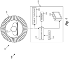
- FIG. 1 depicts an example PET system 100, as used by some embodiments described herein.
- the PET system 100 may generally have an imaging scanner 102 and a PET processing system 108.
- the imaging scanner 102 includes a plurality of detectors 104 arranged in a circular manner about a subject 106, e.g., a patient.
- the detectors 104 are arranged on the inside surface of a cylindrical structure, and the subject 106 is placed within the cylinder so that the detectors 104 surround the subject 106 on all sides.
- Each of the detectors 104 may further be rotatable around the subject 106. While the detectors 104 shown herein are rectangular in shape, those skilled in the art will recognize that the detectors 104 may be in any shape without departing from the scope of this disclosure.
- a radiopharmaceutical is first injected into the subject 106.
- the radiopharmaceutical contains a targeting aspect which interacts with a molecule or process of interest within the patient's body, such as glucose metabolism.
- the radiopharmaceutical also contains a positron-emitting radionuclide. An emitted positron will collide with an electron from a nearby atom, and the positron and the electron annihilate. As a result of the annihilation, two different photons are emitted in substantially opposite directions along a line of response. The photons both travel at the substantially same speed.
- the detectors 104 record these photons, along with PET imaging data associated with the photons, such as the time each photon is detected.
- the PET imaging scanner 102 passes the PET imaging data recorded by the detectors 104 on to a PET processing system 108.
- the PET imaging scanner 102 and the PET processing system 108 are shown and described herein as being separate systems.
- the PET imaging scanner 102 and the PET processing system 108 can be part of a single, unitary system.
- the PET imaging data is sent to an image processor 110, and then stored in a memory 112 in list mode format.
- the image processor 110 processes the PET imaging data, and generates images of the imaged subject 106.
- the resulting images can be shown on a display 114 associated with the image processor 110.
- a user input 116 such as a keyboard and/or mouse device may be provided for a user to manipulate the resulting images shown on the display 114, e.g., image zooming, image rotation, etc.
- the PET processing system 108 further includes a time of flight (ToF) unit 118, configured to calculate a position along each line of response where the annihilation occurred, thus increasing the resolution of the PET image reconstruction.
- the precise time that each of the coincident photons is detected by the detectors 104 is recorded. Since the closer photon will arrive at its detector first, the difference in arrival times helps pin down the location of the annihilation event along the line of response.
- a ToF-PET scan is performed.
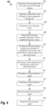
- FIG. 2 illustrates a flowchart of a method of deriving an estimated respiratory signal from acquisition data, according to some embodiments described herein. It should be noted that, although the PET system 100 is used as example for implementing the method described herein, the method can be readily adapted to other imaging modalities including, without limitation SPECT, MRI, and CT.
- ToF acquisition data is projected into a time-series of 3D image volumes, and each 3D image volume is rendered with the Cartesian coordinate system (i.e., (x,y,z)).
- the imaging scanner 102 detects pairs of gamma rays emitted indirectly by a positron-emitting radionuclide.
- a positron is annihilated by an electron
- two gamma photons are simultaneously produced and travel in approximately opposite directions.
- the gamma photons are detected by a pair of oppositely disposed radiation detectors 104 that produce a signal in response to the interaction of the gamma photons with a scintillation crystal.
- the ToF unit 118 measures the difference ⁇ t between the detection times of the two gamma photons arising from a positron annihilation event. This measurement allows the annihilation event to be localized along line(s)-of-response (LOR). This approximate localization is effective in reducing the random coincidence rate and in improving the signal-to-noise ratio (SNR) of the signal, especially when imaging large objects.
- the "ToF" coordinate, ⁇ t is stored together with the location of the two crystals that detect the photon pair.
- the ToF PET data, including ⁇ t, and the location is acquired and stored in list mode format.
- digitized signals are coded with "time marks” as they are received in sequence and stored as individual events as they occur.
- the ToF PET data is projected into a time-series of 3D image volumes having Cartesian coordinates (also called “Cartesian volumes”), by placing each LOR into a single voxel located at the center of the ToF window.
- a first respiratory signal is estimated.
- the measurement of distribution e.g., standard deviation, full-with-half maximum measurement, etc.
- the measurement of distribution e.g., standard deviation, full-with-half maximum measurement, etc.
- the measurement of distribution can be any measurement that quantifies the amount of variation or dispersion of a set of data values.
- r sd ( t ) is the first respiratory signal
- P is a 3D Cartesian volume at time t
- s.d is a standard deviation operator.
- the standard deviations of all the Cartesian volumes reflect activity distribution in the Y direction (the anterior-posterior axis), for example, when the subject 106 (e.g., a patient) breathes in, the abdomen expands and the standard deviation is increased, while when the subject 106 breathes out, the abdomen contracts and the standard deviation is decreased.
- the polarity of the first respiratory signal gradient can clearly indicate the direction of abdomen motion (i.e., breathing in or breathing out).
- the first respiratory signal lacks accuracy, especially for certain anatomical regions.
- the abdominal wall is subject to more anterior-posterior motion during respiration than, for instance, the chest.
- the first respiratory signal may lack accuracy for chest region.
- a Fast Fourier Transform is performed to divide the first respiratory signal into its frequency components, a dominant respiratory frequency is then identified by determining a peak of the spectral magnitude of the frequency components within a predefined frequency range and within a predefined temporal range.
- Equation 2 illustrates identification of a dominant respiratory frequency of the first respiratory signal: arg max f ⁇ f 1 , f 2 R sd
- R sd is FFT of the first respiratory signal
- f 1 and f 2 respectively define a starting frequency and an ending frequency of a frequency range.
- the frequency range should be wide enough to cover the dominant respiratory frequency.
- An example frequency range is 0.1 Hz to 0.4 Hz, which covers the typical dominant respiratory frequency of around 0.2 Hz.
- the example frequency range can be set, e.g., as 0.8 Hz to 1.2 Hz, because the dominant cardiac frequency is around 1 Hz.
- the frequency range can be set to look for a specific type of periodic motion, e.g., a respiratory motion, or a cardiac motion, etc.
- a spatial filter is applied to the 3D Cartesian volumes obtained in the step 202.
- the Cartesian volumes generated during the step 202 are very noisy.
- a spatial filter e.g., a 3D Gaussian filter, is thus applied to the Cartesian volumes to reduce noises.
- the filtered Cartesian volumes are Fast Fourier transformed (FFT) in the temporal domain.
- the filtered Cartesian volumes are divided into a plurality of axial sections along Z direction (i.e., superior-inferior axis), each axial section having a predetermined length.
- the axial sections overlap by a predetermined amount, e.g., 90%.
- a spectral analysis is then performed on each individual axial section, to locate specific acquisition data which is subject to respiratory motion.
- each axial section has the same length, e.g., 10 cm.
- the length of each axial section can be adjusted based on an axial field of view of the PET imaging scanner 102, a bed speed, and a type of radiopharmaceutical.
- lengths of axial sections can be different from each other, instead of a same length.
- the overlap amounts can be different from each other, instead of a same amount.
- the length of axial sections and the overlap amount can be changed for different acquisitions and different scanners.
- the spectral analysis on a signal includes applying a window that selects a spectral segment of the signal for analysis.
- One example method for performing the spectral analysis is described in Schleyer et al. PMB 2009 "Retrospective Data-Driven Respiratory Gating for PET/CT. " However, it should be understood that other similar techniques for performing spectral analysis generally known in the art may be used.
- the estimated dominant respiratory frequency obtained in the step 206 is used to specify the center of the window.
- the spectral analysis thus creates a window around the dominant respiratory frequency estimated in the step 206.
- a phase weighted mask is created for each axial section, to identify voxels that are subject to a respiratory motion.
- phase weighting of each mask is used to separate regions of each mask according to different directions of motion (i.e., separating what is moving "up” from what is moving “down”). For example, if the patient breathes in, the direction of the motion is moving up, while if the patient breathes out, the direction of the motion is moving down. While separation of regions corresponding to different directions of motion is achieved, the absolute direction of motion is not known.
- the relationship between the phase weights and the direction of motion can be different at different axial locations due to an irregular nature of the motion and properties of FFT.
- a phase optimization is performed to ensure that there is a consistent relationship between the phase weights and the direction of motion at each of the phase weighted masks generated at the step 210, and further ensure a consistent relationship between a polarity of the respiratory signal gradient and the direction of motion for all individual axial sections.
- an optimal phase-shift angle is calculated for each phase weighted mask generated in the step 210 (i.e., an optimal phase-shift angle is calculated for each axial section).
- the phase weight at each (x,y,z) location in a mask, i.e., ⁇ xyz is offset by the optimal phase-shift angle ⁇ opt to produce a corrected phase weight ⁇ xyz ′ , as illustrated in Equation 3.
- ⁇ xyz ′ ⁇ xyz ⁇ ⁇ opt
- the optimal phase-shift angle ⁇ opt for each axial range, is defined as an angle that minimizes the difference between the overlapping sections of the phase-weighted masks (because axial sections overlap, thus the phase-weighted masks also overlap).
- the optimal phase-shift angle ensures that a consistent phase weighting is applied to all the different axial regions. This helps prevent the spontaneous phase flipping that may occur at different axial locations.
- Each optimal phase-shift angle can be found through an exhaustive search or a heuristic search. After the phase of each axial section is corrected or optimized, all phase-weighted masks are combined into a single three-dimensional mask, so that a periodic motion during the entire axial scan can be identified.
- the phase optimization step is an in-place operation (i.e., the phase-shift of a given axial range is implemented before progressing to the next range), and thus, the result of the phase optimization step depends on an axial starting point. Therefore, in one embodiment, the axial starting point is determined as an axial location where the largest mean spectral magnitude within the frequency window [ f 1, f 2] was found in the first respiratory signal. In another embodiment, the axial starting point is determined as the center of the overall axial range of the acquisition.
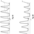
- the single three-dimensional mask is multiplied by the filtered Cartesian volumes of the step 208, and the resulting Cartesian volumes are summed together to produce a second estimated respiratory signal (as shown in FIG. 3B ).
- the single three-dimensional mask can extract Cartesian volumes that are subject to a respiratory motion, thus the resulting Cartesian volumes indicative of displacement of the whole patient body can be used to generate the second estimated respiratory signal. Due to the single three-dimensional mask constructed from the phase-optimized individual masks, the resulting Cartesian volumes have a consistent relationship between the polarity of respiratory motion gradient and the direction of respiratory motion across the entire axial field of view.
- a positive increase in motion signal results from inspiration (breathing in), while a negative decrease in motion signal results from expiration (breathing out).
- a positive increase in motion signal results from expiration, while a negative decrease in motion signal results from inspiration.
- the relationship between the polarity of the motion signal gradient and the direction of the motion signal is consistent.
- a final estimated respiratory signal is generated based on the first estimated respiratory signal generated at the step 204 and the second estimated respiratory signal generated at the step 214.
- This final estimated respiratory signal has a consistent and absolute relationship between the polarity of respiratory motion gradient and the physical direction of motion for the entire length of the scan.
- the first respiratory signal from the step 204 is obtained by calculating standard deviation of each Cartesian volume in the Y direction (the anterior-posterior axis), thus the first respiratory signal can be used to decide the absolute direction of the motion of the patient. Accordingly, the first respiratory signal from the step 204 and the second estimated respiratory signal from the step 214 are used together to derive the final estimated respiratory signal.
- the absolute motion direction of the final estimated respiratory signal can be obtained from the first respiratory signal, while the consistent relationship between the polarity of the signal gradient and the physical direction of motion can be obtained from the second more accurate respiratory signal.
- FIG. 4 illustrates another flowchart of a method 400 of deriving an estimated respiratory signal from acquisition data, according to some embodiments described herein.
- the steps 402-416 are similar to the steps 202-216 of FIG. 2 .
- the only difference is that the step of applying a spatial filter (step 404, corresponding to the step 208 of FIG. 2 ) is performed prior to the step of estimating a first respiratory signal (step 406, corresponding to the step 204 of FIG. 2 ).
- a curve normalization is performed on the final estimated respiratory signal for the later gating step 420.
- the final respiratory signal is estimated from different axial sections of the patient body as the patient moves through the scanner, and there are different intensities of activity and different amplitudes of motion for each anatomical region or each axial section of the patient. Therefore, the relationship between the amplitude of the respiratory signal and amplitude of the breathing is arbitrary in scale at different axial sections, and thus a curve normalization is further performed on the final estimated respiratory signal.
- the normalization approach is performed in four steps. During the first normalization step, referring to FIG.
- low frequency drift of the final estimated respiratory signal is removed by fitting a spline 502 to the final estimated respiratory signal.
- r step 2 [ t ] is the curve generated by the second normalization step at a time point t.
- the amplitude of the final estimated respiratory signal is normalized.
- the final estimated respiratory signal is divided by a standard deviation within a sliding window (e.g., 90 seconds) of the final estimated respiratory signal, as illustrated in Equation 5.
- r step 3 t r step 2 t s . d . r step 2 t ⁇ w : t + w
- r step 3 [ t ] is the curve generated by the third normalization step at a time point t
- r step 2 [ t ] is the curve generated by the second normalization step at a time point t
- s . d. ⁇ r step 2 [ t - w : t + w ] ⁇ is the standard deviation of the curve from the second normalization step in the time range [t-w, t+w], where 2 ⁇ w defines the width of the sliding window.
- the minimum curve 504 of the final estimated respiratory signal is subtracted from the final estimated respiratory signal to baseline correct the final estimated respiratory signal, as illustrated in Equation 6.
- r step 4 t r step 3 t ⁇ min r step 3 t ⁇ v : t + v
- r step 4 [ t ] is the curve generated by the fourth normalization step at a time point t
- r step 3 [ t ] is the curve generated by the third normalization step at time-point t
- min ⁇ r step 3 [ t - v : t + v ] ⁇ is the minimum of the curve from the third normalization step in the time range [ t - v : t + v ], where 2 ⁇ v defines the width of a sliding window.
- an adaptive gating method is employed to correct for temporal variations in the amplitude of the respiratory signal (i.e., potential non-linear variations in the relationship between signal amplitude and physical motion amplitude).
- a dynamic optimal gate is created to allow for intra-acquisition changes in both respiratory signal amplitude and a shape (i.e., unevenness of the respiratory signal curve due to different anatomical regions being imaged at different times during the acquisition).
- the optimal gate is defined as the smallest amplitude range which covers a pre-determined fraction (e.g., 35%) of acquisition time of the respiratory signal.
- the patient spends as much acquisition time as possible while having a minimum motion. For example, the patient spends a majority of acquisition time on the expiration (e.g., 35%) while having minimum motion.
- the noises can be reduced if there is more acquisition time, while the blurring can be reduced if there is less motion (i.e., smaller amplitude range).
- the optimal gate is a trade-off between the more acquisition time and the less motion.
- the size of the time window i.e., a pre-determined fraction of acquisition time) is an adjustable parameter.
- a temporally variant optimal amplitude range 602 is calculated using a sliding window (e.g., 90 seconds) approach. This temporally variant optimal amplitude range 602 can be directly used to gate the PET acquisition into a single optimal sinogram.
- the respiratory signal can be dynamically normalized using the temporally variant optimal amplitude range, and a single (i.e., static) amplitude range 604 can then be used to gate the acquisition.
- the single (i.e., static) amplitude range 604 defines an optimal gate for the entire duration of the acquisition.
- motion correction can be performed based on the optimal gate and the final respiratory signal estimated at step 216, and then a whole body PET image with motion correction is reconstructed.
- the method, system, and article of manufacture of this disclosure require no physical motion monitoring devices, and apply data-driven gating to whole body PET acquired with continuous bed motion. A consistent relationship between the polarity of the respiratory signal gradient and the direction of motion is provided throughout the image acquisition.
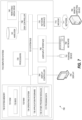
- FIG. 7 illustrates an exemplary computing environment 700 within which embodiments of the invention may be implemented.
- this computing environment 700 may be used to implement a method of deriving a motion signal from imaging data, as illustrated in FIGS. 2 and 4 .
- the computing environment 700 may be used to implement one or more of the components illustrated in the system 100 of FIG. 1 .
- the computing environment 700 may include computer system 710, which is one example of a computing system upon which embodiments of the invention may be implemented.
- Computers and computing environments, such as computer system 710 and computing environment 700 are known to those of skill in the art and thus are described briefly here.
- the computer system 710 may include a communication mechanism such as a bus 721 or other communication mechanism for communicating information within the computer system 710.
- the computer system 710 further includes one or more processors 720 coupled with the bus 721 for processing the information.
- the processors 720 may include one or more central processing units (CPUs), graphical processing units (GPUs), or any other processor known in the art.
- the computer system 710 also includes a system memory 730 coupled to the bus 721 for storing information and instructions to be executed by processors 720.
- the system memory 730 may include computer readable storage media in the form of volatile and/or nonvolatile memory, such as read only memory (ROM) 731 and/or random access memory (RAM) 732.
- the system memory RAM 732 may include other dynamic storage device(s) (e.g., dynamic RAM, static RAM, and synchronous DRAM).
- the system memory ROM 731 may include other static storage device(s) (e.g., programmable ROM, erasable PROM, and electrically erasable PROM).
- the system memory 730 may be used for storing temporary variables or other intermediate information during the execution of instructions by the processors 720.
- BIOS basic input/output system
- BIOS basic routines that help to transfer information between elements within computer system 710, such as during start-up, may be stored in ROM 731.
- RAM 732 may contain data and/or program modules that are immediately accessible to and/or presently being operated on by the processors 720.
- System memory 730 may additionally include, for example, operating system 734, application programs 735, other program modules 736 and program data 737.
- the computer system 710 also includes a disk controller 740 coupled to the bus 721 to control one or more storage devices for storing information and instructions, such as a hard disk 741 and a removable media drive 742 (e.g., floppy disk drive, compact disc drive, tape drive, and/or solid state drive).
- a hard disk 741 and a removable media drive 742 e.g., floppy disk drive, compact disc drive, tape drive, and/or solid state drive.
- the storage devices may be added to the computer system 710 using an appropriate device interface (e.g., a small computer system interface (SCSI), integrated device electronics (IDE), Universal Serial Bus (USB), or FireWire).
- SCSI small computer system interface
- IDE integrated device electronics
- USB Universal Serial Bus
- FireWire FireWire
- the computer system 710 may also include a display controller 765 coupled to the bus 721 to control a display 766, such as a cathode ray tube (CRT) or liquid crystal display (LCD), for displaying information to a computer user.
- the computer system includes an input interface 760 and one or more input devices, such as a keyboard 762 and a pointing device 761, for interacting with a computer user and providing information to the processors 720.
- the pointing device 761 for example, may be a mouse, a trackball, or a pointing stick for communicating direction information and command selections to the processor 720 and for controlling cursor movement on the display 766.
- the display 766 may provide a touch screen interface which allows input to supplement or replace the communication of direction information and command selections by the pointing device 761.
- the computer system 710 may perform a portion of or all of the processing steps of embodiments of the invention in response to the processors 720 executing one or more sequences of one or more instructions contained in a memory, such as the system memory 730.
- a memory such as the system memory 730.
- Such instructions may be read into the system memory 730 from another computer readable medium, such as a hard disk 741 or a removable media drive 742.
- the hard disk 741 may contain one or more data stores and data files used by embodiments of the present invention. Data store contents and data files may be encrypted to improve security.
- the processors 720 may also be employed in a multi-processing arrangement to execute the one or more sequences of instructions contained in system memory 730.
- hard-wired circuitry may be used in place of or in combination with software instructions. Thus, embodiments are not limited to any specific combination of hardware circuitry and software.
- the computer system 710 may include at least one computer readable medium or memory for holding instructions programmed according to embodiments of the invention and for containing data structures, tables, records, or other data described herein.
- the term "computer readable medium” as used herein refers to any medium that participates in providing instructions to the processors 720 for execution.
- a computer readable medium may take many forms including, but not limited to, non-volatile media, volatile media, and transmission media.
- Non-limiting examples of non-volatile media include optical disks, solid state drives, magnetic disks, and magneto-optical disks, such as hard disk 741 or removable media drive 742.
- Non-limiting examples of volatile media include dynamic memory, such as system memory 730.
- Non-limiting examples of transmission media include coaxial cables, copper wire, and fiber optics, including the wires that make up the bus 721. Transmission media may also take the form of acoustic or light waves, such as those generated during radio wave and infrared data communications.
- the computing environment 700 may further include the computer system 710 operating in a networked environment using logical connections to one or more remote computers, such as remote computer 780.
- Remote computer 780 may be a personal computer (laptop or desktop), a mobile device, a server, a router, a network PC, a peer device or other common network node, and typically includes many or all of the elements described above relative to computer system 710.
- computer system 710 may include modem 772 for establishing communications over a network 771, such as the Internet. Modem 772 may be connected to bus 721 via user network interface 770, or via another appropriate mechanism.
- Network 771 may be any network or system generally known in the art, including the Internet, an intranet, a local area network (LAN), a wide area network (WAN), a metropolitan area network (MAN), a direct connection or series of connections, a cellular telephone network, or any other network or medium capable of facilitating communication between computer system 710 and other computers (e.g., remote computer 780).
- the network 771 may be wired, wireless or a combination thereof. Wired connections may be implemented using Ethernet, Universal Serial Bus (USB), RJ-11 or any other wired connection generally known in the art.
- Wireless connections may be implemented using Wi-Fi, WiMAX, and Bluetooth, infrared, cellular networks, satellite or any other wireless connection methodology generally known in the art. Additionally, several networks may work alone or in communication with each other to facilitate communication in the network 771.
- the embodiments of the present disclosure may be implemented with any combination of hardware and software.
- the embodiments of the present disclosure may be included in an article of manufacture (e.g., one or more computer program products) having, for example, computer-readable, non-transitory media.
- the media has embodied therein, for instance, computer readable program code for providing and facilitating the mechanisms of the embodiments of the present disclosure.
- the article of manufacture can be included as part of a computer system or sold separately.
- An executable application comprises code or machine readable instructions for conditioning the processor to implement predetermined functions, such as those of an operating system, a context data acquisition system or other information processing system, for example, in response to user command or input.
- An executable procedure is a segment of code or machine readable instruction, sub-routine, or other distinct section of code or portion of an executable application for performing one or more particular processes. These processes may include receiving input data and/or parameters, performing operations on received input data and/or performing functions in response to received input parameters, and providing resulting output data and/or parameters.
- a graphical user interface comprises one or more display images, generated by a display processor and enabling user interaction with a processor or other device and associated data acquisition and processing functions.
- the GUI also includes an executable procedure or executable application.
- the executable procedure or executable application conditions the display processor to generate signals representing the GUI display images. These signals are supplied to a display device which displays the image for viewing by the user.
- the processor under control of an executable procedure or executable application, manipulates the GUI display images in response to signals received from the input devices. In this way, the user may interact with the display image using the input devices, enabling user interaction with the processor or other device.
- An activity performed automatically is performed in response to one or more executable instructions or device operation without user direct initiation of the activity.
Landscapes
- Health & Medical Sciences (AREA)
- Engineering & Computer Science (AREA)
- Life Sciences & Earth Sciences (AREA)
- Medical Informatics (AREA)
- Public Health (AREA)
- General Health & Medical Sciences (AREA)
- Radiology & Medical Imaging (AREA)
- Nuclear Medicine, Radiotherapy & Molecular Imaging (AREA)
- Physics & Mathematics (AREA)
- Biomedical Technology (AREA)
- Animal Behavior & Ethology (AREA)
- Biophysics (AREA)
- High Energy & Nuclear Physics (AREA)
- Optics & Photonics (AREA)
- Pathology (AREA)
- Veterinary Medicine (AREA)
- Heart & Thoracic Surgery (AREA)
- Molecular Biology (AREA)
- Surgery (AREA)
- Computer Vision & Pattern Recognition (AREA)
- Epidemiology (AREA)
- Primary Health Care (AREA)
- Human Computer Interaction (AREA)
- General Physics & Mathematics (AREA)
- Multimedia (AREA)
- Theoretical Computer Science (AREA)
- Physiology (AREA)
- Nuclear Medicine (AREA)
- Image Analysis (AREA)
- Apparatus For Radiation Diagnosis (AREA)
- Studio Devices (AREA)
- Magnetic Resonance Imaging Apparatus (AREA)
Claims (14)
- Computerimplementiertes Verfahren zum Ableiten eines periodischen Bewegungssignals aus Bildgebungsdaten für kontinuierliche Erfassung einer Bettbewegung, das Verfahren umfassend:Erfassen einer Zeitreihe von dreidimensionalen Bildvolumen;Schätzen (204) eines ersten Bewegungssignals durch eine Verteilungsmessung jedes dreidimensionalen Bildvolumens, wobei das erste Bewegungssignal verwendet werden kann, eine absolute Bewegungsrichtung eines Patienten zu bestimmen;Aufteilen (210) der Zeitreihe von dreidimensionalen Bildvolumen in eine Vielzahl von Axialabschnitten, die einander um einen im Voraus bestimmten Betrag überlappen, wobei jeder Axialabschnitt eine im Voraus bestimmte Länge aufweist;Durchführen (210) einer Spektralanalyse an jedem Axialabschnitt, um eine Vielzahl von dreidimensionalen Bildvolumen zu lokalisieren, die einer periodischen Bewegung unterliegen;Durchführen (212) einer Phasenoptimierung an jedem Axialabschnitt, um eine dreidimensionale Maske zu erhalten;Schätzen (214) eines zweiten Bewegungssignals durch die dreidimensionale Maske und der Zeitreihe von dreidimensionalen Bildvolumen, wobei das zweite Bewegungssignal ein konsistentes Verhältnis zwischen einer Polarität eines periodischen Bewegungssignalgradienten und einer Richtung der periodischen Bewegung aufweist; undSchätzen (216) eines endgültigen Bewegungssignals basierend auf dem ersten Bewegungssignal und dem zweiten Bewegungssignal, wobei eine absolute Bewegungsrichtung des endgültigen Bewegungssignals aus dem ersten Bewegungssignal und dem konsistenten Verhältnis zwischen der Polarität des Bewegungssignalgradienten erhalten wird und die Richtung der periodischen Bewegung aus dem zweiten Bewegungssignal erhalten wird.
- Verfahren nach Anspruch 1, ferner umfassend:Identifizieren (206) einer dominanten Bewegungsfrequenz des ersten Bewegungssignals in einem im Voraus definierten Frequenzbereich; undDurchführen (210) der Spektralanalyse an jedem Axialabschnitt unter Verwendung der dominanten Bewegungsfrequenz.
- Verfahren nach Anspruch 1, ferner umfassend:
Anwenden (208) eines Raumfilters auf die Zeitreihe von dreidimensionalen Bildvolumen vor dem Aufteilen der Zeitreihe von dreidimensionalen Bildvolumen in eine Vielzahl von Axialabschnitten, die einander überlappen. - Verfahren nach Anspruch 1, ferner umfassend:Erzeugen einer phasengewichteten Maske für jeden Axialabschnitt bei der Spektralanalyse;Berechnen eines optimalen Phasenverschiebungswinkels für jede phasengewichtete Maske, um eine Differenz zwischen überlappenden Abschnitten von phasengewichteten Masken bei der Phasenoptimierung zu minimieren; undKombinieren sämtlicher der phasengewichteten Masken, um die dreidimensionale Maske zu bilden.
- Verfahren nach Anspruch 1, der Schritt des Schätzens des zweiten Bewegungssignals ferner umfassend:Multiplizieren der dreidimensionalen Maske mit der Zeitreihe von dreidimensionalen Bildvolumen; undSummieren der resultierenden dreidimensionalen Bildvolumen, um das zweite Bewegungssignal zu schätzen.
- Verfahren nach Anspruch 1, der Schritt des Schätzens (216) des endgültigen Bewegungssignals ferner umfassend:
Bestimmen der Richtung der periodischen Bewegung, die mit dem endgültigen Bewegungssignal assoziiert ist, unter Verwendung des ersten Bewegungssignals. - Verfahren nach Anspruch 1, ferner umfassend:Normalisieren (418) des endgültigen Bewegungssignals; undErlangen eines optimalen Tors, um vorübergehende Variationen einer Amplitude des endgültigen Bewegungssignals zu korrigieren, wobei das optimale Tor der kleinste Amplitudenbereich ist, der eine im Voraus bestimmte Fraktion der Erfassungszeit des endgültigen Bewegungssignals abdeckt.
- Verfahren nach Anspruch 7, der Schritt des Normalisierens (418) des endgültigen Bewegungssignals ferner umfassend:Entfernen eines Frequenzdrifts des endgültigen Bewegungssignals durch Anbringen einer Spline an das endgültige Bewegungssignal;Subtrahieren der Spline von dem endgültigen Bewegungssignal;Normalisieren der Amplitude des endgültigen Bewegungssignals; undDurchführen von Grundlinienkorrektur an dem endgültigen Bewegungssignal.
- Verfahren nach Anspruch 1, wobei die periodische Bewegung eine Atmungsbewegung oder eine Herzbewegung ist.
- System zum Ableiten eines periodischen Bewegungssignals aus Bildgebungsdaten für kontinuierliche Erfassung einer Bettbewegung, das System umfassend:einen Bildgebungsabtaster zum Erfassen einer Zeitreihe von dreidimensionalen Bildvolumen; undein Computersystem, konfiguriert zum:Schätzen eines ersten Bewegungssignals durch eine Verteilungsmessung jedes dreidimensionalen Bildvolumens, wobei das erste Bewegungssignal verwendet werden kann, eine absolute Bewegungsrichtung eines Patienten zu bestimmen;Anwenden eines Raumfilters auf die Zeitreihe von dreidimensionalen Bildvolumen, wodurch eine Vielzahl von gefilterten dreidimensionalen Bildvolumen erhalten wird;Aufteilen des gefilterten dreidimensionalen Bildvolumens in eine Vielzahl von Axialabschnitten, die einander um einen im Voraus bestimmten Betrag überlappen, wobei jeder Axialabschnitt eine im Voraus bestimmte Länge aufweist;Durchführen einer Spektralanalyse an jedem Axialabschnitt, um eine Vielzahl von dreidimensionalen Bildvolumen zu lokalisieren, die einer periodischen Bewegung unterliegen;Durchführen einer Phasenoptimierung an jedem Axialabschnitt, um eine dreidimensionale Maske zu erhalten;Schätzen eines zweiten Bewegungssignals durch die dreidimensionale Maske und der Zeitreihe von dreidimensionalen Bildvolumen, wobei das zweite Bewegungssignal ein konsistentes Verhältnis zwischen einer Polarität eines periodischen Bewegungssignalgradienten und einer Richtung der periodischen Bewegung aufweist; undSchätzen eines endgültigen Bewegungssignals basierend auf dem ersten Bewegungssignal und dem zweiten Bewegungssignal, wobei die Richtung der periodischen Bewegung, die mit dem endgültigen Bewegungssignal assoziiert ist, durch das erste Bewegungssignal bestimmt wird und wobei das konsistente Verhältnis zwischen der Polarität des Bewegungssignalgradienten und der Richtung der periodischen Bewegung aus dem zweiten Bewegungssignal bestimmt wird.
- System nach Anspruch 10, wobei das Computersystem ferner konfiguriert ist zum Durchführen der Verfahrensschritte nach einem der Ansprüche 2, 4, 5, 7 oder 8.
- Fertigungsartikel zum Ableiten eines Atmungssignals aus Bildgebungsdaten für kontinuierliche Erfassung einer Bettbewegung, der Fertigungsartikel umfassend ein nichttransitorisches materielles computerlesbares Medium, das computerausführbare Anweisungen hält, die, wenn sie durch einen Computer ausgeführt werden, den Computer veranlassen, ein Verfahren durchzuführen, umfassend:Erfassen einer Zeitreihe von dreidimensionalen Bildvolumen;Schätzen (204) eines ersten Atmungssignals durch eine Verteilungsmessung jedes dreidimensionalen Bildvolumens, wobei das erste Bewegungssignal verwendet werden kann, eine absolute Bewegungsrichtung eines Patienten zu bestimmen;Anwenden (208) eines Raumfilters auf die Zeitreihe von dreidimensionalen Bildvolumen, wodurch eine Vielzahl von gefilterten dreidimensionalen Bildvolumen erhalten wird;Aufteilen (210) der gefilterten dreidimensionalen Bildvolumen in eine Vielzahl von Axialabschnitten, die einander um einen im Voraus bestimmten Betrag überlappen, wobei jeder Axialabschnitt eine im Voraus bestimmte Länge aufweist:Durchführen (210) einer Spektralanalyse an jedem Axialabschnitt, um eine Vielzahl von dreidimensionalen Bildvolumen zu lokalisieren, die einer Atmungsbewegung unterliegen;Durchführen (212) einer Phasenoptimierung an jedem Axialabschnitt, um eine dreidimensionale Maske zu erhalten;Schätzen (214) eines zweiten Atmungssignals durch die dreidimensionale Maske und der Zeitreihe von dreidimensionalen Bildvolumen, wobei das zweite Atmungssignal ein konsistentes Verhältnis zwischen einer Polarität eines Atmungssignalgradienten und einer Richtung der Atmungsbewegung aufweist; undSchätzen (216) eines endgültigen Atmungssignals basierend auf dem ersten Atmungssignal und dem zweiten Atmungssignal, wobei eine absolute Bewegungsrichtung des endgültigen Bewegungssignals aus dem ersten Bewegungssignal und dem konsistenten Verhältnis zwischen der Polarität des Bewegungssignalgradienten erhalten wird und die Richtung der periodischen Bewegung aus dem zweiten Bewegungssignal erhalten wird.
- Fertigungsartikel nach Anspruch 12, wobei das Verfahren ferner die Verfahrensschritte nach einem der Ansprüche 5, 7 oder 8 umfasst.
- Fertigungsartikel nach Anspruch 13, wobei mindestens zwei Axialabschnitte verschiedene Längen aufweisen und mindestens zwei Paare von aneinander angrenzenden Axialabschnitten um verschiedene Beträge überlappen.
Priority Applications (1)
| Application Number | Priority Date | Filing Date | Title |
|---|---|---|---|
| EP23191881.4A EP4270413A3 (de) | 2018-04-05 | 2019-03-27 | Von bilddaten abgeleitetes bewegungssignal |
Applications Claiming Priority (2)
| Application Number | Priority Date | Filing Date | Title |
|---|---|---|---|
| US201862652942P | 2018-04-05 | 2018-04-05 | |
| PCT/US2019/024211 WO2019195044A1 (en) | 2018-04-05 | 2019-03-27 | Motion signal derived from imaging data |
Related Child Applications (2)
| Application Number | Title | Priority Date | Filing Date |
|---|---|---|---|
| EP23191881.4A Division EP4270413A3 (de) | 2018-04-05 | 2019-03-27 | Von bilddaten abgeleitetes bewegungssignal |
| EP23191881.4A Division-Into EP4270413A3 (de) | 2018-04-05 | 2019-03-27 | Von bilddaten abgeleitetes bewegungssignal |
Publications (3)
| Publication Number | Publication Date |
|---|---|
| EP3759718A1 EP3759718A1 (de) | 2021-01-06 |
| EP3759718B1 true EP3759718B1 (de) | 2023-11-08 |
| EP3759718C0 EP3759718C0 (de) | 2023-11-08 |
Family
ID=66290530
Family Applications (2)
| Application Number | Title | Priority Date | Filing Date |
|---|---|---|---|
| EP19719990.4A Active EP3759718B1 (de) | 2018-04-05 | 2019-03-27 | Bewegungssignal, abgeleitet aus bilddaten |
| EP23191881.4A Pending EP4270413A3 (de) | 2018-04-05 | 2019-03-27 | Von bilddaten abgeleitetes bewegungssignal |
Family Applications After (1)
| Application Number | Title | Priority Date | Filing Date |
|---|---|---|---|
| EP23191881.4A Pending EP4270413A3 (de) | 2018-04-05 | 2019-03-27 | Von bilddaten abgeleitetes bewegungssignal |
Country Status (7)
| Country | Link |
|---|---|
| US (1) | US11622742B2 (de) |
| EP (2) | EP3759718B1 (de) |
| JP (1) | JP7005789B2 (de) |
| CN (1) | CN111937080B (de) |
| CA (1) | CA3096034A1 (de) |
| IL (1) | IL275960A (de) |
| WO (1) | WO2019195044A1 (de) |
Families Citing this family (5)
| Publication number | Priority date | Publication date | Assignee | Title |
|---|---|---|---|---|
| US11410354B2 (en) * | 2020-02-25 | 2022-08-09 | Uih America, Inc. | System and method for motion signal recalibration |
| CN113823378B (zh) * | 2020-06-19 | 2024-11-15 | 华为技术有限公司 | 运动次数的确定方法和终端 |
| CN112998734B (zh) * | 2021-02-24 | 2023-09-26 | 明峰医疗系统股份有限公司 | Pet-ct扫描设备的运动信号分析方法、系统及计算机可读存储介质 |
| EP4329605A4 (de) * | 2021-09-02 | 2024-06-19 | Shanghai United Imaging Healthcare Co., Ltd. | Systeme und verfahren zur medizinischen bildgebung |
| JP2024082179A (ja) * | 2022-12-07 | 2024-06-19 | 富士フイルムヘルスケア株式会社 | 体動情報処理装置、磁気共鳴撮像装置、、及び体動情報処理方法 |
Family Cites Families (23)
| Publication number | Priority date | Publication date | Assignee | Title |
|---|---|---|---|---|
| US6490476B1 (en) * | 1999-10-14 | 2002-12-03 | Cti Pet Systems, Inc. | Combined PET and X-ray CT tomograph and method for using same |
| US20020086217A1 (en) * | 2000-12-27 | 2002-07-04 | Bablumyan Arkady S. | Holographic manufacture of coherence detectors |
| US6915004B2 (en) * | 2002-02-28 | 2005-07-05 | Cti Pet Systems, Inc. | Continuous tomography bed motion data processing apparatus and method |
| JP2005177212A (ja) | 2003-12-22 | 2005-07-07 | Canon Inc | 放射線画像処理装置、放射線画像処理システム、放射線撮影システム、放射線撮影装置、放射線画像処理方法、コンピュータ可読記憶媒体、及びプログラム |
| DE102004006548B4 (de) | 2004-02-10 | 2006-10-19 | Siemens Ag | Verfahren zur Planung der Strahlentherapie eines Patienten und CT-System hierzu und zur Erstellung von CT-Aufnahmen |
| US20100185085A1 (en) * | 2009-01-19 | 2010-07-22 | James Hamilton | Dynamic ultrasound processing using object motion calculation |
| CN101855564B (zh) * | 2007-11-09 | 2014-08-20 | 皇家飞利浦电子股份有限公司 | Mr-pet周期运动门控和校正 |
| RU2554378C2 (ru) * | 2009-12-10 | 2015-06-27 | Конинклейке Филипс Электроникс Н.В. | Способ и устройство для использования времяпролетной информации для обнаружения и введения поправки на движение в сканограммах |
| US20120078089A1 (en) * | 2010-09-23 | 2012-03-29 | General Electric Company | Method and apparatus for generating medical images |
| EP2515138A1 (de) * | 2011-04-19 | 2012-10-24 | Koninklijke Philips Electronics N.V. | Bewegungsausgelöste Magnetresonanzbildgebung mit APT/CEST |
| WO2012153219A1 (en) * | 2011-05-12 | 2012-11-15 | Koninklijke Philips Electronics N.V. | Motion compensated imaging |
| US10940332B2 (en) * | 2011-05-19 | 2021-03-09 | The Trustees Of Dartmouth College | Cherenkov imaging systems and methods to monitor beam profiles and radiation dose while avoiding interference from room lighting |
| US8966701B2 (en) * | 2012-06-14 | 2015-03-03 | Joseph Dellecave | Sole wipe |
| DE102012218289A1 (de) * | 2012-10-08 | 2014-04-10 | Siemens Aktiengesellschaft | Bewegungskorrigierte PET-Bilder |
| CN103605117B (zh) * | 2013-12-05 | 2015-06-03 | 西安电子科技大学 | 基于干扰抑制的相控阵信号失真实时校正方法 |
| WO2016179585A1 (en) * | 2015-05-07 | 2016-11-10 | The Cleveland Clinic Foundation | Motion corrected imaging system |
| CN107850652B (zh) * | 2015-07-15 | 2021-10-15 | 皇家飞利浦有限公司 | 具有运动检测的mr成像 |
| EP3349658B1 (de) | 2015-09-16 | 2022-08-03 | Koninklijke Philips N.V. | Respiratorische bewegungskompensation für vierdimensionale computertomografische bildgebung mittels ultraschall |
| US9990741B2 (en) * | 2015-09-28 | 2018-06-05 | Siemens Medical Solutions Usa, Inc. | Motion correction in a projection domain in time of flight positron emission tomography |
| CN105266813B (zh) * | 2015-11-30 | 2018-10-12 | 中国科学院深圳先进技术研究院 | 一种自门控三维心脏成像的运动信号提取方法及装置 |
| CN107133549B (zh) * | 2016-02-29 | 2020-11-24 | 上海联影医疗科技有限公司 | Ect运动门控信号获取方法及ect图像重建方法 |
| CN107580159B (zh) * | 2016-06-30 | 2020-06-02 | 华为技术有限公司 | 信号校正方法、装置及终端 |
| WO2019060557A1 (en) | 2017-09-25 | 2019-03-28 | Bradford Company | FOLDED PANEL, ITS MANUFACTURING METHOD AND PRODUCTS MANUFACTURED FROM ONE OR MORE OF THESE FOLDED PANELS |
-
2019
- 2019-03-27 JP JP2020554104A patent/JP7005789B2/ja active Active
- 2019-03-27 US US15/733,498 patent/US11622742B2/en active Active
- 2019-03-27 EP EP19719990.4A patent/EP3759718B1/de active Active
- 2019-03-27 CA CA3096034A patent/CA3096034A1/en active Pending
- 2019-03-27 WO PCT/US2019/024211 patent/WO2019195044A1/en not_active Ceased
- 2019-03-27 CN CN201980022100.5A patent/CN111937080B/zh active Active
- 2019-03-27 EP EP23191881.4A patent/EP4270413A3/de active Pending
-
2020
- 2020-07-09 IL IL275960A patent/IL275960A/en unknown
Also Published As
| Publication number | Publication date |
|---|---|
| CN111937080A (zh) | 2020-11-13 |
| EP4270413A3 (de) | 2023-12-27 |
| US11622742B2 (en) | 2023-04-11 |
| EP3759718A1 (de) | 2021-01-06 |
| US20210106301A1 (en) | 2021-04-15 |
| CN111937080B (zh) | 2024-05-14 |
| JP7005789B2 (ja) | 2022-02-10 |
| WO2019195044A1 (en) | 2019-10-10 |
| IL275960A (en) | 2020-08-31 |
| JP2021520488A (ja) | 2021-08-19 |
| EP3759718C0 (de) | 2023-11-08 |
| CA3096034A1 (en) | 2019-10-10 |
| EP4270413A2 (de) | 2023-11-01 |
Similar Documents
| Publication | Publication Date | Title |
|---|---|---|
| EP3759718B1 (de) | Bewegungssignal, abgeleitet aus bilddaten | |
| US9911208B2 (en) | Apparatus and method of iterative image reconstruction using regularization-parameter control | |
| US10605880B2 (en) | Respiratory phase-resolved 3D body imaging using iterative motion correction and average | |
| CN1926578B (zh) | 运动补偿 | |
| US20120281897A1 (en) | Method and apparatus for motion correcting medical images | |
| US10360697B2 (en) | Fast sparse computed tomography image reconstruction from few views | |
| US8588488B2 (en) | Group-wise image registration based on motion model | |
| US12141898B2 (en) | Continuous bed motion acquisition with axially short phantom for PET imaging system setup and quality control | |
| US10064593B2 (en) | Image reconstruction for a volume based on projection data sets | |
| Carles et al. | Evaluation of PET texture features with heterogeneous phantoms: complementarity and effect of motion and segmentation method | |
| EP3399346B1 (de) | Normierungskristalleffizienzschätzung für die kontinuierliche bewegungsbetterfassung | |
| Büther et al. | External radioactive markers for PET data-driven respiratory gating in positron emission tomography | |
| US20130202172A1 (en) | Alignment of positron emission tomographs by virtual tomographs | |
| Li et al. | Multienergy cone-beam computed tomography reconstruction with a spatial spectral nonlocal means algorithm | |
| US9342882B2 (en) | Methods and systems for determining the concentration of a contrast agent | |
| Fuangrod et al. | An independent system for real-time dynamic multileaf collimation trajectory verification using EPID | |
| O’Connell et al. | A prospective gating method to acquire a diverse set of free-breathing CT images for model-based 4DCT | |
| Blake et al. | Thoracic motion‐compensated cone‐beam computed tomography in under 20 seconds on a fast‐rotating linac: a simulation study | |
| Qiao et al. | Joint model of motion and anatomy for PET image reconstruction | |
| Thomas et al. | Investigating the minimum scan parameters required to generate free-breathing motion artefact-free fast-helical CT | |
| Rit et al. | Respiratory motion correction in cone-beam CT for image-guided radiotherapy | |
| US11704795B2 (en) | Quality-driven image processing | |
| Hu et al. | Gated reconstruction for PET scan with continuous bed motion |
Legal Events
| Date | Code | Title | Description |
|---|---|---|---|
| STAA | Information on the status of an ep patent application or granted ep patent |
Free format text: STATUS: UNKNOWN |
|
| STAA | Information on the status of an ep patent application or granted ep patent |
Free format text: STATUS: THE INTERNATIONAL PUBLICATION HAS BEEN MADE |
|
| PUAI | Public reference made under article 153(3) epc to a published international application that has entered the european phase |
Free format text: ORIGINAL CODE: 0009012 |
|
| STAA | Information on the status of an ep patent application or granted ep patent |
Free format text: STATUS: REQUEST FOR EXAMINATION WAS MADE |
|
| 17P | Request for examination filed |
Effective date: 20201002 |
|
| AK | Designated contracting states |
Kind code of ref document: A1 Designated state(s): AL AT BE BG CH CY CZ DE DK EE ES FI FR GB GR HR HU IE IS IT LI LT LU LV MC MK MT NL NO PL PT RO RS SE SI SK SM TR |
|
| AX | Request for extension of the european patent |
Extension state: BA ME |
|
| DAV | Request for validation of the european patent (deleted) | ||
| DAX | Request for extension of the european patent (deleted) | ||
| GRAP | Despatch of communication of intention to grant a patent |
Free format text: ORIGINAL CODE: EPIDOSNIGR1 |
|
| STAA | Information on the status of an ep patent application or granted ep patent |
Free format text: STATUS: GRANT OF PATENT IS INTENDED |
|
| INTG | Intention to grant announced |
Effective date: 20230606 |
|
| RIN1 | Information on inventor provided before grant (corrected) |
Inventor name: JONES, JUDSON P. Inventor name: HONG, INKI Inventor name: SCHLEYER, PAUL |
|
| GRAS | Grant fee paid |
Free format text: ORIGINAL CODE: EPIDOSNIGR3 |
|
| GRAA | (expected) grant |
Free format text: ORIGINAL CODE: 0009210 |
|
| STAA | Information on the status of an ep patent application or granted ep patent |
Free format text: STATUS: THE PATENT HAS BEEN GRANTED |
|
| AK | Designated contracting states |
Kind code of ref document: B1 Designated state(s): AL AT BE BG CH CY CZ DE DK EE ES FI FR GB GR HR HU IE IS IT LI LT LU LV MC MK MT NL NO PL PT RO RS SE SI SK SM TR |
|
| REG | Reference to a national code |
Ref country code: GB Ref legal event code: FG4D |
|
| REG | Reference to a national code |
Ref country code: CH Ref legal event code: EP |
|
| REG | Reference to a national code |
Ref country code: DE Ref legal event code: R096 Ref document number: 602019041035 Country of ref document: DE |
|
| REG | Reference to a national code |
Ref country code: IE Ref legal event code: FG4D |
|
| U01 | Request for unitary effect filed |
Effective date: 20231130 |
|
| U07 | Unitary effect registered |
Designated state(s): AT BE BG DE DK EE FI FR IT LT LU LV MT NL PT SE SI Effective date: 20231206 |
|
| PG25 | Lapsed in a contracting state [announced via postgrant information from national office to epo] |
Ref country code: GR Free format text: LAPSE BECAUSE OF FAILURE TO SUBMIT A TRANSLATION OF THE DESCRIPTION OR TO PAY THE FEE WITHIN THE PRESCRIBED TIME-LIMIT Effective date: 20240209 |
|
| PG25 | Lapsed in a contracting state [announced via postgrant information from national office to epo] |
Ref country code: IS Free format text: LAPSE BECAUSE OF FAILURE TO SUBMIT A TRANSLATION OF THE DESCRIPTION OR TO PAY THE FEE WITHIN THE PRESCRIBED TIME-LIMIT Effective date: 20240308 |
|
| U20 | Renewal fee for the european patent with unitary effect paid |
Year of fee payment: 6 Effective date: 20240318 |
|
| PG25 | Lapsed in a contracting state [announced via postgrant information from national office to epo] |
Ref country code: ES Free format text: LAPSE BECAUSE OF FAILURE TO SUBMIT A TRANSLATION OF THE DESCRIPTION OR TO PAY THE FEE WITHIN THE PRESCRIBED TIME-LIMIT Effective date: 20231108 |
|
| PG25 | Lapsed in a contracting state [announced via postgrant information from national office to epo] |
Ref country code: IS Free format text: LAPSE BECAUSE OF FAILURE TO SUBMIT A TRANSLATION OF THE DESCRIPTION OR TO PAY THE FEE WITHIN THE PRESCRIBED TIME-LIMIT Effective date: 20240308 Ref country code: GR Free format text: LAPSE BECAUSE OF FAILURE TO SUBMIT A TRANSLATION OF THE DESCRIPTION OR TO PAY THE FEE WITHIN THE PRESCRIBED TIME-LIMIT Effective date: 20240209 Ref country code: ES Free format text: LAPSE BECAUSE OF FAILURE TO SUBMIT A TRANSLATION OF THE DESCRIPTION OR TO PAY THE FEE WITHIN THE PRESCRIBED TIME-LIMIT Effective date: 20231108 |
|
| PG25 | Lapsed in a contracting state [announced via postgrant information from national office to epo] |
Ref country code: RS Free format text: LAPSE BECAUSE OF FAILURE TO SUBMIT A TRANSLATION OF THE DESCRIPTION OR TO PAY THE FEE WITHIN THE PRESCRIBED TIME-LIMIT Effective date: 20231108 Ref country code: PL Free format text: LAPSE BECAUSE OF FAILURE TO SUBMIT A TRANSLATION OF THE DESCRIPTION OR TO PAY THE FEE WITHIN THE PRESCRIBED TIME-LIMIT Effective date: 20231108 Ref country code: NO Free format text: LAPSE BECAUSE OF FAILURE TO SUBMIT A TRANSLATION OF THE DESCRIPTION OR TO PAY THE FEE WITHIN THE PRESCRIBED TIME-LIMIT Effective date: 20240208 Ref country code: HR Free format text: LAPSE BECAUSE OF FAILURE TO SUBMIT A TRANSLATION OF THE DESCRIPTION OR TO PAY THE FEE WITHIN THE PRESCRIBED TIME-LIMIT Effective date: 20231108 |
|
| PG25 | Lapsed in a contracting state [announced via postgrant information from national office to epo] |
Ref country code: CZ Free format text: LAPSE BECAUSE OF FAILURE TO SUBMIT A TRANSLATION OF THE DESCRIPTION OR TO PAY THE FEE WITHIN THE PRESCRIBED TIME-LIMIT Effective date: 20231108 |
|
| PG25 | Lapsed in a contracting state [announced via postgrant information from national office to epo] |
Ref country code: SK Free format text: LAPSE BECAUSE OF FAILURE TO SUBMIT A TRANSLATION OF THE DESCRIPTION OR TO PAY THE FEE WITHIN THE PRESCRIBED TIME-LIMIT Effective date: 20231108 |
|
| PG25 | Lapsed in a contracting state [announced via postgrant information from national office to epo] |
Ref country code: SM Free format text: LAPSE BECAUSE OF FAILURE TO SUBMIT A TRANSLATION OF THE DESCRIPTION OR TO PAY THE FEE WITHIN THE PRESCRIBED TIME-LIMIT Effective date: 20231108 Ref country code: SK Free format text: LAPSE BECAUSE OF FAILURE TO SUBMIT A TRANSLATION OF THE DESCRIPTION OR TO PAY THE FEE WITHIN THE PRESCRIBED TIME-LIMIT Effective date: 20231108 Ref country code: RO Free format text: LAPSE BECAUSE OF FAILURE TO SUBMIT A TRANSLATION OF THE DESCRIPTION OR TO PAY THE FEE WITHIN THE PRESCRIBED TIME-LIMIT Effective date: 20231108 Ref country code: CZ Free format text: LAPSE BECAUSE OF FAILURE TO SUBMIT A TRANSLATION OF THE DESCRIPTION OR TO PAY THE FEE WITHIN THE PRESCRIBED TIME-LIMIT Effective date: 20231108 |
|
| REG | Reference to a national code |
Ref country code: DE Ref legal event code: R097 Ref document number: 602019041035 Country of ref document: DE |
|
| PLBE | No opposition filed within time limit |
Free format text: ORIGINAL CODE: 0009261 |
|
| STAA | Information on the status of an ep patent application or granted ep patent |
Free format text: STATUS: NO OPPOSITION FILED WITHIN TIME LIMIT |
|
| 26N | No opposition filed |
Effective date: 20240809 |
|
| REG | Reference to a national code |
Ref country code: CH Ref legal event code: PL |
|
| PG25 | Lapsed in a contracting state [announced via postgrant information from national office to epo] |
Ref country code: MC Free format text: LAPSE BECAUSE OF FAILURE TO SUBMIT A TRANSLATION OF THE DESCRIPTION OR TO PAY THE FEE WITHIN THE PRESCRIBED TIME-LIMIT Effective date: 20231108 |
|
| PG25 | Lapsed in a contracting state [announced via postgrant information from national office to epo] |
Ref country code: MC Free format text: LAPSE BECAUSE OF FAILURE TO SUBMIT A TRANSLATION OF THE DESCRIPTION OR TO PAY THE FEE WITHIN THE PRESCRIBED TIME-LIMIT Effective date: 20231108 |
|
| PG25 | Lapsed in a contracting state [announced via postgrant information from national office to epo] |
Ref country code: IE Free format text: LAPSE BECAUSE OF NON-PAYMENT OF DUE FEES Effective date: 20240327 |
|
| PG25 | Lapsed in a contracting state [announced via postgrant information from national office to epo] |
Ref country code: IE Free format text: LAPSE BECAUSE OF NON-PAYMENT OF DUE FEES Effective date: 20240327 Ref country code: CH Free format text: LAPSE BECAUSE OF NON-PAYMENT OF DUE FEES Effective date: 20240331 |
|
| U20 | Renewal fee for the european patent with unitary effect paid |
Year of fee payment: 7 Effective date: 20250320 |
|
| PGFP | Annual fee paid to national office [announced via postgrant information from national office to epo] |
Ref country code: GB Payment date: 20250403 Year of fee payment: 7 |
|
| PG25 | Lapsed in a contracting state [announced via postgrant information from national office to epo] |
Ref country code: CY Free format text: LAPSE BECAUSE OF FAILURE TO SUBMIT A TRANSLATION OF THE DESCRIPTION OR TO PAY THE FEE WITHIN THE PRESCRIBED TIME-LIMIT; INVALID AB INITIO Effective date: 20190327 |
|
| PG25 | Lapsed in a contracting state [announced via postgrant information from national office to epo] |
Ref country code: HU Free format text: LAPSE BECAUSE OF FAILURE TO SUBMIT A TRANSLATION OF THE DESCRIPTION OR TO PAY THE FEE WITHIN THE PRESCRIBED TIME-LIMIT; INVALID AB INITIO Effective date: 20190327 |
|
| PG25 | Lapsed in a contracting state [announced via postgrant information from national office to epo] |
Ref country code: TR Free format text: LAPSE BECAUSE OF FAILURE TO SUBMIT A TRANSLATION OF THE DESCRIPTION OR TO PAY THE FEE WITHIN THE PRESCRIBED TIME-LIMIT Effective date: 20231108 |