EP3759477B1 - Laufzeit-beugungswandler-anordnung und verfahren zur prüfung eines prüfkörpers mit diesem system - Google Patents
Laufzeit-beugungswandler-anordnung und verfahren zur prüfung eines prüfkörpers mit diesem system Download PDFInfo
- Publication number
- EP3759477B1 EP3759477B1 EP19715184.8A EP19715184A EP3759477B1 EP 3759477 B1 EP3759477 B1 EP 3759477B1 EP 19715184 A EP19715184 A EP 19715184A EP 3759477 B1 EP3759477 B1 EP 3759477B1
- Authority
- EP
- European Patent Office
- Prior art keywords
- transducer
- transducer assembly
- test piece
- transducer elements
- assembly
- Prior art date
- Legal status (The legal status is an assumption and is not a legal conclusion. Google has not performed a legal analysis and makes no representation as to the accuracy of the status listed.)
- Active
Links
Images


Classifications
-
- G—PHYSICS
- G01—MEASURING; TESTING
- G01N—INVESTIGATING OR ANALYSING MATERIALS BY DETERMINING THEIR CHEMICAL OR PHYSICAL PROPERTIES
- G01N29/00—Investigating or analysing materials by the use of ultrasonic, sonic or infrasonic waves; Visualisation of the interior of objects by transmitting ultrasonic or sonic waves through the object
- G01N29/04—Analysing solids
- G01N29/043—Analysing solids in the interior, e.g. by shear waves
-
- G—PHYSICS
- G01—MEASURING; TESTING
- G01N—INVESTIGATING OR ANALYSING MATERIALS BY DETERMINING THEIR CHEMICAL OR PHYSICAL PROPERTIES
- G01N29/00—Investigating or analysing materials by the use of ultrasonic, sonic or infrasonic waves; Visualisation of the interior of objects by transmitting ultrasonic or sonic waves through the object
- G01N29/04—Analysing solids
- G01N29/06—Visualisation of the interior, e.g. acoustic microscopy
- G01N29/0654—Imaging
- G01N29/069—Defect imaging, localisation and sizing using, e.g. time of flight diffraction [TOFD], synthetic aperture focusing technique [SAFT], Amplituden-Laufzeit-Ortskurven [ALOK] technique
-
- G—PHYSICS
- G01—MEASURING; TESTING
- G01N—INVESTIGATING OR ANALYSING MATERIALS BY DETERMINING THEIR CHEMICAL OR PHYSICAL PROPERTIES
- G01N29/00—Investigating or analysing materials by the use of ultrasonic, sonic or infrasonic waves; Visualisation of the interior of objects by transmitting ultrasonic or sonic waves through the object
- G01N29/04—Analysing solids
- G01N29/07—Analysing solids by measuring propagation velocity or propagation time of acoustic waves
-
- G—PHYSICS
- G01—MEASURING; TESTING
- G01N—INVESTIGATING OR ANALYSING MATERIALS BY DETERMINING THEIR CHEMICAL OR PHYSICAL PROPERTIES
- G01N29/00—Investigating or analysing materials by the use of ultrasonic, sonic or infrasonic waves; Visualisation of the interior of objects by transmitting ultrasonic or sonic waves through the object
- G01N29/22—Details, e.g. general constructional or apparatus details
- G01N29/24—Probes
- G01N29/2437—Piezoelectric probes
-
- G—PHYSICS
- G01—MEASURING; TESTING
- G01N—INVESTIGATING OR ANALYSING MATERIALS BY DETERMINING THEIR CHEMICAL OR PHYSICAL PROPERTIES
- G01N29/00—Investigating or analysing materials by the use of ultrasonic, sonic or infrasonic waves; Visualisation of the interior of objects by transmitting ultrasonic or sonic waves through the object
- G01N29/22—Details, e.g. general constructional or apparatus details
- G01N29/24—Probes
- G01N29/2487—Directing probes, e.g. angle probes
-
- G—PHYSICS
- G01—MEASURING; TESTING
- G01N—INVESTIGATING OR ANALYSING MATERIALS BY DETERMINING THEIR CHEMICAL OR PHYSICAL PROPERTIES
- G01N29/00—Investigating or analysing materials by the use of ultrasonic, sonic or infrasonic waves; Visualisation of the interior of objects by transmitting ultrasonic or sonic waves through the object
- G01N29/22—Details, e.g. general constructional or apparatus details
- G01N29/32—Arrangements for suppressing undesired influences, e.g. temperature or pressure variations, compensating for signal noise
-
- G—PHYSICS
- G01—MEASURING; TESTING
- G01N—INVESTIGATING OR ANALYSING MATERIALS BY DETERMINING THEIR CHEMICAL OR PHYSICAL PROPERTIES
- G01N2291/00—Indexing codes associated with group G01N29/00
- G01N2291/01—Indexing codes associated with the measuring variable
- G01N2291/011—Velocity or travel time
-
- G—PHYSICS
- G01—MEASURING; TESTING
- G01N—INVESTIGATING OR ANALYSING MATERIALS BY DETERMINING THEIR CHEMICAL OR PHYSICAL PROPERTIES
- G01N2291/00—Indexing codes associated with group G01N29/00
- G01N2291/02—Indexing codes associated with the analysed material
- G01N2291/023—Solids
- G01N2291/0234—Metals, e.g. steel
-
- G—PHYSICS
- G01—MEASURING; TESTING
- G01N—INVESTIGATING OR ANALYSING MATERIALS BY DETERMINING THEIR CHEMICAL OR PHYSICAL PROPERTIES
- G01N2291/00—Indexing codes associated with group G01N29/00
- G01N2291/02—Indexing codes associated with the analysed material
- G01N2291/028—Material parameters
- G01N2291/0289—Internal structure, e.g. defects, grain size, texture
-
- G—PHYSICS
- G01—MEASURING; TESTING
- G01N—INVESTIGATING OR ANALYSING MATERIALS BY DETERMINING THEIR CHEMICAL OR PHYSICAL PROPERTIES
- G01N2291/00—Indexing codes associated with group G01N29/00
- G01N2291/10—Number of transducers
- G01N2291/102—Number of transducers one emitter, one receiver
-
- G—PHYSICS
- G01—MEASURING; TESTING
- G01N—INVESTIGATING OR ANALYSING MATERIALS BY DETERMINING THEIR CHEMICAL OR PHYSICAL PROPERTIES
- G01N2291/00—Indexing codes associated with group G01N29/00
- G01N2291/26—Scanned objects
- G01N2291/263—Surfaces
-
- G—PHYSICS
- G01—MEASURING; TESTING
- G01N—INVESTIGATING OR ANALYSING MATERIALS BY DETERMINING THEIR CHEMICAL OR PHYSICAL PROPERTIES
- G01N29/00—Investigating or analysing materials by the use of ultrasonic, sonic or infrasonic waves; Visualisation of the interior of objects by transmitting ultrasonic or sonic waves through the object
- G01N29/22—Details, e.g. general constructional or apparatus details
- G01N29/26—Arrangements for orientation or scanning by relative movement of the head and the sensor
Definitions
- the present disclosure relates to a time-of-flight diffraction (TOFD) transducer assembly for use in detecting an anomaly in a test piece. Aspects of the invention relate to a transducer assembly and a TOFD system.
- TOFD time-of-flight diffraction
- HTHA high temperature hydrogen attack
- UK Patent Publication No. 2 198 532 A in the name of ATOMIC ENERGY AUTHORITY UK refers in lines 3 to 7 of page 1 thereof to "an apparatus and a method for performing ultrasonic inspection of objects, and in particular to apparatus for performing ultrasonic time-of-flight diffraction (TOFD) inspection of underwater objects".
- TOFD time-of-flight diffraction
- US Patent Publication No. 2005/223807 A1 in the name of BARDOUX et al. refers in paragraph [0001] thereof to "a method for the nondestructive inspection, by ultrasound, of materials and, more particularly, of welds joining two metal workpieces together, edge to edge, in particular of the plate or sheet kind".
- French Patent Application No. 3 011 332 A1 in the name of AREVA NP refers - according to a machine translation thereof - in lines 7 to 10 of page 1 thereof to "a method and a device for non-destructive testing by ultrasound of a weld carried out in a part of a nuclear reactor and in particular in a steam generator, in a vessel or a pressurizer of a nuclear reactor".
- US Patent No. 5 156 050 A in the name of SCHMID et al. refers in lines 5 to 7 of column 1 thereof to "an ultrasonic probe for ultrasonically testing screws by the pulse echo method, and a method for operating the probe".
- US Patent No. 5 922 961 A in the name of HSU et al . refers in lines 6 to 9 of column 1 thereof to "ultrasonic microscope systems used in the analysis of the properties of solid samples and, more particularly, to an improved acoustic microscope system".
- a dual element time-of-flight diffraction (TOFD) transducer assembly for use in detecting a microscopic anomaly in a test piece arising from high temperature hydrogen attack (HTHA), the transducer assembly comprising a first transducer element having a central frequency between 5MHz and 20MHz configured to transmit ultrasonic signals to the test piece, and a second transducer element having a central frequency between 5MHz and 20MHz configured to receive diffracted ultrasonic signals from the test piece, the first and second transducer elements each being arranged with a roof angle between 0° and 10°, wherein the first and second transducer elements are housed within a common housing, the housing also forming part of the transducer assembly.
- TOFD time-of-flight diffraction
- a transducer assembly which is capable of detecting microscopic defects, such as those that arise as a result of high temperature hydrogen attack (HTHA), using time-of-flight diffraction (TOFD) methods.
- HTHA high temperature hydrogen attack
- TOFD time-of-flight diffraction
- the assembly may be a small and convenient unit which can access hard to reach locations, and may be replaced easily in the event of a fault arising.
- the transducer assembly is a highly-sensitive and high resolution ultrasonic probe with an adjustable focal depth which is configurable to detect microscopic defects at any useful depth in a test piece.
- the transducer assembly may comprise transducer elements comprising the first and second transducer elements.
- the first and second transducer elements may each be damped.
- the first and second transducer elements are each preferably heavily-damped.
- the first and second transducer elements may have a maximum probe centre spacing (PCS) of approximately 50mm.
- PCS probe centre spacing
- the transducer elements may comprise only the first transducer element and the second transducer element and no other transducer element.
- the first and second transducer elements may each have a preferred central frequency between 7MHz and 15MHz, and an optimal central frequency of 10MHz.
- the transducer assembly may further comprise a backing material adhered to each of the first and second transducer elements, the backing material being configured to damp the first and second transducer elements.
- the backing material supporting the transducer element has a great influence on the damping characteristics of the transducer. Using a backing material with acoustic impedance similar to that of the active element will produce the most effective damping. Such a transducer will have a wider bandwidth resulting in higher sensitivity. As the mismatch in acoustic impedance between the active element and the backing material increases, material penetration increases but transducer sensitivity is reduced.
- the backing material may be substantially made of a tungsten-loaded adhesive. Between approximately 70% and 90% of the backing material may be tungsten powder by weight. The backing material optimally comprises 1 part adhesive to 5 parts tungsten powder by weight. The backing material has a total mass between approximately 0.04g and 0.06g, and an optimal total mass of 0.0509g (or 0.05g).
- the first and second transducer elements preferably have a PCS between approximately 5mm and 50mm. In some embodiments, the first and second transducer elements have a PCS between approximately 5mm and 30mm, or typically between approximately 5mm and 15mm. The first and second transducer elements may have an optimal PCS between approximately 6mm and 8mm.
- the transducer assembly may be configured with a focal depth of at least approximately 10mm. Typically, the transducer assembly is configured with a focal depth of at least approximately 25mm.
- the transducer assembly may be configured with an infinite focal depth.
- the first and second transducer elements are arranged with a roof angle between approximately 0° and 7°.
- the first and second transducer elements are arranged with a roof angle between approximately 2.1° and 6°.
- the first and second transducer elements are arranged with a roof angle of approximately 0°.
- the transducer assembly may further comprise a first wedge portion and a second wedge portion for mounting the first and second transducer elements, respectively.
- the first and second wedge portions may each have a thickness between approximately 3mm and 8mm, and optimally approximately 4mm.
- the first transducer element may be fixedly attached to the first wedge portion and the second transducer element may be fixedly attached to the second wedge portion by means of an adhesive.
- the transducer assembly may further comprise a sound absorbing medium positioned between the first and second transducer elements, the sound absorbing medium sonically separating the first and second transducer elements.
- the sound absorbing medium may also be positioned between the first and second wedge portions, the sound absorbing medium also sonically separating the first and second wedge portions.
- the sound absorbing medium may be substantially made of cork.
- the transducer assembly may further comprise an electrical connection means configured to electrically couple the first and second transducer elements to a flaw detector.
- the transducer assembly may further comprise a couplant distribution means configured to distribute couplant on the test piece.
- the transducer assembly may further comprise a traversing apparatus connection means configured to releasably attach the transducer assembly to a traversing apparatus.
- the first and second transducer elements may each consist of a piezocomposite element.
- the first and second transducer elements may each have a circular shape and have a diameter between approximately 4mm and 8mm, preferably approximately 6mm.
- the particular parameters of the transducer assembly including the PCS and/or the central frequency and/or the degree of damping and/or the roof of the first and second transducer elements, will be selected according to the requirements for detection. For example, it may be that a particular user requires several transducer assemblies in order to provide a full range of detection possibilities, depending on the nature of the anomalies to be detected and on the depth at which it is expected the anomalies will be detected within the sample under test. To detect anomalies of one type at one depth, one particular set of parameters will be selected and to detect another type of anomaly at another depth a slightly different set of parameters will be selected.
- the parameters are selected from the above stated ranges and values, and the inventors have made the surprising discovering that selecting the parameters within the stated ranges, and at the typical values, provides a particularly useful detection assembly which can detect a nature of microscopic anomaly (e.g. HTHA) which cannot readily be detected, nor with such speed and ease, using conventional means.
- a nature of microscopic anomaly e.g. HTHA
- the transducer assembly forms one of a set of transducer assemblies, when sold, so as to provide the user with multiple detection possibilities.
- a TOFD system comprises the transducer assembly described above and a flaw detector, wherein the flaw detector is coupled to the first and second transducer elements at the electrical connection means.
- the flaw detector may be configured to: provide the transducer assembly with electrical drive signals for conversion by the transducer assembly into the ultrasonic signals to be transmitted to the test piece, receive electrical output signals derived from diffracted ultrasonic signals converted by the transducer assembly, analyse the received electrical output signals with respect to the electrical drive signals to determine the anomaly of the test piece, and output data relating to the anomaly of the test piece.
- the invention extends to a method of detecting a microscopic anomaly in a test piece using the TOFD system described above; the method comprising the steps of: providing the TOFD system, arranging the transducer assembly of the TOFD system on the test piece above the anomaly, causing the flaw detector of the TOFD system to produce electrical drive signals and to provide the first transducer assembly with said electrical drive signals via the electrical connection means of the TOFD system, causing the transducer assembly to convert the electrical drive signals into ultrasonic signals and to transmit said ultrasonic signals into the test piece to diffract at the microscopic anomaly and propagate back towards the transducer assembly, causing the transducer assembly to convert diffracted ultrasonic signals into electrical output signals and to provide the flaw detector with said electrical output signals via the electrical connection means, causing the flaw detector to analyse the electrical output signals with respect to the electrical drive signals to determine the anomaly of the test piece, and causing the flaw detector to output data relating to the anomaly of the test piece.
- Time-of-flight Diffraction is a non-destructive testing technique that uses diffraction of transmitted ultrasonic signals to identify the presence of anomalies in an article.
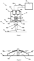
- Figure 1 shows a transducer assembly 10, or probe, positioned on a first surface 72 of a test piece 70 such as a pipe or plate.
- the test piece 70 is substantially made of steel.
- the test piece 70 comprises a microscopic anomaly 78, typically smaller than 50 ⁇ m, located between the first surface 72 and a second surface 75 of the test piece 70.
- the microscopic anomaly 78 is a defect such as a crack or fissure (or micro-fissure) which may have arisen as a result of High Temperature Hydrogen Attack (HTHA), or even creep. If left untreated, such microscopic anomalies 78 can lead to a destructive end of such a pipe or plate.
- HTHA High Temperature Hydrogen Attack
- the transducer assembly 10 is configured to transmit consecutive ultrasound signals 85a into the test piece 70. In doing so, the transducer assembly 10 spreads ultrasound signals over a wide area that includes the microscopic defect 78. Unlike other detection techniques, the TOFD transducer assembly 10 does not focus signals 85a on one particular location. As some of the transmitted ultrasound signals 85a have sufficiently high frequencies, they diffract at the microscopic defect 78 in the test piece 70 and propagate back towards the transducer assembly 10. The transducer assembly 10 is further configured to receive the diffracted ultrasound signals 85b from the test piece 70, thereby allowing the microscopic defect 78 to be detected.
- the transducer assembly 10 comprises transducer elements 35a, 35b consisting of a first transducer element 35a and a second transducer element 35b. That is, the transducer assembly 10 has only two transducer elements (i.e. it is a dual-element transducer assembly 10), in contrast to phased-array transducers.
- the first and second transducer elements 35a, 35b are configured to convert electrical signals into ultrasonic signals, and vice versa.
- the first transducer element 35a On receipt of an electrical drive signal, the first transducer element 35a transmits an ultrasonic signal 85a into the test piece 70.
- the second transducer element 35b produces an electrical output signal.
- first and second transducer elements 35a, 35b are the same, with any one being configured as a transmitter transducer and the other being configured as a receiver transducer. Whether the first and second transducer elements 35a, 35b act as a transmitter or receiver depends only on the connection of the transducer 10 to a flaw detector 90, and how the transducer elements 35a, 35b are driven.
- the transducer assembly 10 Since the transducer assembly 10 has only two transducer elements 35a, 35b, the transducer assembly 10 is simple, cheap-to-produce and easily-replaceable. Moreover, since there are only two transducer elements 35a, 35b, the transducer assembly 10 is operable to detect defects much quicker than other transducer modules that include a plurality of transducer elements, such as phased array probes, which require more complex control processes and more detailed data processing.
- the transducer elements 35a, 35b of transducer assembly 10 are configured to transmit ultrasound signals 85a with a large proportion of sufficiently high frequencies and are arranged close together. To this end, the transducer elements 35a, 35b are heavily-damped and are housed within a common housing, as will now be detailed.
- a backing material 37a, 37b which may be made of a tungsten-loaded adhesive is adhered to each of the first and second transducer elements, 35a, 35b respectively.
- the backing material may be an adhesive material which is loaded with a damping material, for example a tungsten-loaded adhesive.
- a tungsten-loaded adhesive comprises an adhesive (such as Araldite ® ) and tungsten.
- the adhesive is "tungsten-loaded" because it comprises a high proportion of adhesive. Between approximately 70% and 90% of the backing material may be tungsten powder by weight.
- the backing material 37a, 37b optimally comprises 1 part adhesive to 5 parts tungsten powder by weight.
- the mass of the backing material 37a, 37b may be between approximately 0.04g and 0.06g, and optimally 0.0509g (or 0.05g). The above values are considered optimal because the first and second transducer elements 35a, 35b are sufficiently heavily-damped to transmit the necessary ultrasound signals 85a, but are not so damped that they cannot vibrate and hence transmit ultrasound signals 85a at all.
- the first transducer element 35a transmits ultrasound signals 85a into the test piece with a wide range of frequencies with pulse lengths between approximately 0.4 ⁇ s and 1 ⁇ s (indicating how high the level of damping is). Moreover, an extremely wide bandwidth is achieved. A large proportion of these transmitted ultrasound signals 85a therefore have high enough frequencies that they will diffract at the microscopic defect 78 in the test piece 70. The larger the proportion of the transmitted ultrasound signals 85a with high enough frequencies, the larger the number of high-frequency transmitted ultrasound signals 85a that reach the microscopic defect 78 inside the test piece despite the effects of attenuation.
- the transducer assembly 10 has very high resolution and is configured to distinguish between adjacent anomalies deep inside the test piece 78.
- the first and second transducer elements 35a, 35b are arranged closely together.
- transmitted and diffracted ultrasound signals 85a, 85b need only travel short distances though the test piece 70, thus experiencing minimal attenuation.
- the first and second transducer elements 35a, 35b are housed within a common housing 15 of the transducer assembly 10 and have a maximum probe centre spacing (PCS), or separation, of approximately 50mm.
- PCS probe centre spacing
- the PCS of first and second transducer elements 35a, 35b is defined as the lateral separation between the midpoints of the first and second transducer elements 35a, 35b.
- a PCS of the first and second transducer elements between approximately 5mm and 50mm is preferable, since crosstalk between the first and second transducer elements 35a, 35b is reduced and the signal to noise ratio is improved.
- a PCS of the first and second transducer elements between approximately 6mm and 8mm is considered optimal.
- the transducer assembly 10 is further configured to detect microscopic defects at varying depths.
- the roof angle ⁇ of each of the first and second transducer elements 35a, 35b defines the angle between each of the first and second transducer elements 35a, 35b and the first surface 72 of the test piece 70.
- the transducer assembly 10 is configured with an infinite focal depth.
- the transducer assembly 10 is configured with a smaller focal depth.
- the minimum possible focal depth of the transducer assembly 10 is approximately 25mm, while the maximum possible roof angle for the first and second transducer elements 35a, 35b is approximately 10°. Since the roof angle for the first and second transducer elements 35a, 35b is relatively low, the transducer assembly 10 is configured to detect defects directly therebelow.
- the transducer assembly 10 is a highly-sensitive and high resolution ultrasonic probe with an adjustable focal depth which is configurable to detect microscopic defects at any useful depth in a test piece 70.
- the transducer assembly 10 may also be used to detect the location and size of microscopic anomaly clusters in the test piece 70, and hence give an indication of the extent to which any region of the test piece 70 is deficient.
- the transducer assembly 10 may also be configured to identify the thickness of a test piece 70 such as pipe, by analysing ultrasound signals 88a, 88b which reflect off the second surface 75 of the test piece 70 back towards the transducer assembly 10.
- the transducer assembly 10 comprises a common housing 15 which encloses both the first transducer element 35a and the second transducer element 35b.
- the housing 15 is rigid, and has a substantially cuboid shape that defines an internal volume 28.
- the transducer assembly 10 can beneficially be installed and manipulated by a user by using only one hand.
- the transducer assembly 10 can access hard to reach locations for scanning.
- the housing 15 comprises a baseless box 17 which is integrally formed from an ideally lightweight, ductile and corrosion-resistant material such as aluminium.
- the baseless box 17 comprises an upper wall 21 defining a ceiling of the baseless box, second and third opposing side walls 22, 23 extending perpendicularly from two opposing edges of the upper wall 21, and fourth and fifth opposing side walls 24, 25 extending perpendicularly from the other two opposing edges of the upper wall 21.
- the second and third opposing side walls 22, 23 each abut (and are substantially perpendicular to) the third and fourth opposing side walls 23, 24.
- the upper wall and the side walls 21, 22, 23, 24, 25 each have a substantially rectangular shape.
- the housing 15 further comprises a base section 20, the base section 20 comprising a sound absorbing medium 30 (or sound barrier 30) and first and second wedge portions 32a, 32b.
- the sounds absorbing medium 30 is of substantially cuboid shape.
- Each of the first and second wedge portions 32a, 32b includes a substantially cuboid wedge base, 33a, 33b and a substantially cuboid upper step 34a, 34b, each wedge base, 33a, 33b being integrally formed with the corresponding upper step, 34a, 34b.
- Each wedge base 33a, 33b defines a platform for the respective upper step 34a, 34b.
- the sound absorbing medium 30 is sandwiched between the first and second wedge portions 32a, 32b such that the wedge bases 33a, 33b are substantially flush with a base face 31 of the sound absorbing medium 30.
- the sound absorbing medium 30 is fixedly attached to an internal face 39a, 39b of each wedge portion 32a, 32b, each internal face 39a, 39b comprising a face of the respective wedge base 33a, 33b and a face of the respective upper step 34a, 34b of the wedge portions 32a, 32b.
- the first and second wedge portions 32a, 32b are each fixedly attached, or "paired", to the sound absorbing medium 30 by means of an adhesive such as cyanoacrylate.
- the sound absorbing medium 30 extends perpendicularly away from the wedge bases 33a, 33b.
- the baseless box 17 is fixedly attached to the wedge bases 33a, 33b at the outer rim of the base section 20 by means of an adhesive such as cyanoacrylate such that the upper step 34a, 34b of each of the first and second wedge portions 32a, 32b and the sound absorbing medium 30 extend towards the upper wall 21 of the housing 15.
- the base section 20 is arranged such that the sound absorbing medium 30 abuts and extends between the fourth and fifth opposing side walls 24, 25.
- the sound absorbing medium 30 may abut the upper wall 21, so that the internal volume 28 is divided by the sound absorbing medium 30, or not. When the sound absorbing medium 30 does not abut the upper wall 21, less material of the sound absorbing medium 30 is required.
- the sound absorbing medium 30 sonically separates the first transducer element 35a and the first wedge potion 32a (to which the first transducer element 35a is fixedly mounted on one side of the sound absorbing medium 30) from the second transducer element 35b and the second wedge portion 32b (to which the second transducer element 35b is fixedly mounted on the other side of the sound absorbing medium 30).
- the first and second wedge portions 32a, 32b separate the first and second transducer elements 35a, 35b from the test piece 70 and are a medium through which ultrasonic signals 85a, 85b propagate as they travel from the first transducer element 35a into the test piece 70 and from the test piece 70 into the second transducer element 35b.
- the first and second wedge portions 32a, 32b are made of any suitable material such as crosslink polystyrene.
- the sound absorbing medium 30 therefore mitigates the risk of the second transducer element 35b receiving ultrasound signals directly from the first transducer element 35a that have not been incident on the test piece 70.
- the sound absorbing medium 30 therefore reduces cross talk between the first and second transducer elements 35a, 35b and hence improves the signal to noise ratio.
- the sound absorbing medium 30 may be made of any suitable material such as cork.
- the first and second transducer elements 35a, 35b each consist of a piezocomposite element typically comprising a piezoelectric material and an epoxy. These materials improve the signal to noise ratio of the transducer assembly.
- the central frequency of the elements 35a, 35b is between 5MHz and 20MHz, and optimally 10MHz. At low frequencies, the transducer assembly 10 lacks sensitivity and resolution, while at very high frequencies the transmitted ultrasound signals 85a of the transducer assembly 10 are unlikely to penetrate through the grain structure of the test piece 70. Since the transducer assembly 10 is extremely heavily-damped, transducer elements 35a, 35b with a 10MHz central frequency provide the optimum bandwidth for detecting microscopic defects in a test piece.
- the piezoelectric elements 35a, 35b each have a fully circular disc shape and have a diameter between 3mm to 8 mm, optimally 6mm.
- the size of the piezoelectric elements 35a, 35b ensures a sufficiently wide beam spread for full coverage of the test piece 70. There is a limit on how small the diameter of the elements can be as it is important to ensure the sound waves have sufficient energy to penetrate into the sample under test without suffering significant attenuation.
- the first and second transducer elements 35a, 35b are fixedly attached to the wedge portions 32a, 32b by means of an adhesive such as cyanoacrylate.
- an adhesive such as cyanoacrylate.
- any damage to the first and second transducer elements 35a, 35b that arises due to soldering is avoided. This is particularly beneficial given the sensitivity of piezocomposite crystals to heat.
- no fashioning of dimples or cut-outs in the first and second wedge portions 32a, 32b are required.
- the focal depth of the transducer assembly 10 depends on the roof angle ⁇ of the first and second transducer elements 35a, 35b. Since the first and second transducer elements 35a, 35b are substantially flat discs, to arrange the first and second transducer elements 35a, 35b at a roof angle ⁇ the upper step 34a, 34b of each of the first and second wedge portions 32a, 32b must be shaped accordingly. Therefore by adjusting the roof angle of the first and second wedge portions 32a, 32b, the focal-depth of the transducer 10 is adjusted as necessary.
- the focal depth of the transducer assembly 10 also depends on the sound velocity of the material of the first and second wedge portions 32a, 32b.
- the transducer assembly 10 is configured with a required focal depth by both adjusting the roof angle ⁇ of the first and second transducer elements 35a, 35b, i.e. the roof angle ⁇ of the upper step 34a, 34b of each of the first and second wedge portions 32a, 32b, and the material of the first and second wedge portions 32a, 32b.
- the first and second wedge portions 32a, 32b may, for example, comprise cast acrylic and/ or polyether ether ketone.
- the refraction angle at which transmitted ultrasound signals 85a refract into the test piece 70 and diffracted ultrasound signals refract out of the test piece 70 may also be changed. In doing so, ultrasound signals may be directed out of, and diffracted back into, the transducer at a required angle, thus allowing the transducer 10 to detect microscopic defects at locations other than directly below the transducer 10. This may be particularly useful if one is unable to position the transducer 10 directly above one part of the test piece 70.
- the refraction angle of the first and second wedge portions 32a, 32b may be between 0° and 70°.
- the thickness of the wedge portions 32a, 32b is between approximately 3mm and 8mm and optimally approximately 4mm. Since ultrasound signals attenuate through the wedge portions 32a, 32b, it is beneficial that the wedge potions 32a, 32b be as thin as possible. However, the wedge portions 32a, 32b must be thick enough to allow for wear and tear of the transducer assembly 10.
- the transducer assembly 10 further comprises an electrical connection means 40 comprising a first electrical connection point 40a and a second electrical connection point 40b which are configured to electrically couple the first transducer element 35a and the second transducer element 35b to the flaw detector 90.
- the first and second electrical connection points 40a, 40b may be any suitable electrical connection points including coaxial power connectors such as LEMO connectors or Bayonet Neill-Concelman (BNC) connectors.
- first and second electrical connection points 40a, 40b are securable in place in a first and second respective aperture of the upper wall 21 of the housing 15.
- the first and second electrical connection points 40a, 40b form a tight fit with each respective aperture.
- the first electrical connection point 40a is coupled to the first transducer element 35a via a first electrical connector 50a while the second electrical connection point 40b is coupled to the second transducer element 35b via a second electrical connector 50b.
- the first and second electrical connectors 50a, 50b may be printed circuit boards (PCB) comprising a glass fibre reinforced (fibreglass) epoxy resin with copper foil bonded to one or two sides thereof.
- the first electrical connector 50a provides the first transducer element 35a with the electrical drive signal that is supplied by the flaw detector 90 at the first electrical connection point 40a.
- the second electrical connector 50b provides the flaw detector 90 with the electrical output signal supplied by the second transducer element 35b.
- the first and second electrical connectors 50a, 50b are fixedly attached to the sound absorbing medium 30, one on each side, by means of an adhesive such as cyanoacrylate, the first electrical connector 50a facing the second wall 22 of the housing and the second electrical connector 50b facing the third wall 23 of the housing 15.
- the first and second transducer elements 35a, 35b are coupled to the respective first and second electrical connectors 50a, 50b by means of strips 57a, 57b, 58a, 58b, typically made from silver.
- the first and second transducer elements 35a, 35b are piezocomposite elements which are sensitive to heat.
- silver strips 57a, 57b, 58a, 58b are used as they do not require soldering and can be adhered instead.
- the silver strips 57a, 58a, 57b, 58b are coupled to the first and second respective transducer elements 35a, 35b at one end and to the first and second respective electrical connectors 50a, 50b at the other end.
- the silver strips 57a, 57b, 58a, 58b are fixedly attached to the first and second electrical connectors 50a, 50b by means of soldering.
- the silver strips 57a, 57b are fixedly attached to an upper surface of the first and second respective transducer elements 35a, 35b by means of electric paint, the upper surfaces facing the upper wall 21 of the housing.
- the silver strips 58a, 58b are fixedly attached to a lower surface of the first and second respective transducer elements 35a, 35b by means of electric paint, the lower surfaces facing the first and second respective wedge portions 32a, 32b.
- the silver strips 58a, 58b are arranged to run down side faces of the sound absorbing medium 30.
- the silver strips 57a, 57b, 58a, 58b may be directly attached to the first and second electrical connection points 40a, 40b.
- the first and second electrical connectors 50a, 50b are coupled to the first and second electrical connection points 40a, 40b by cables 52a, 52b, 55a, 55b such as coax cables.
- the cables 55a, 55b couple the first and second electrical connectors 50a, 50b to the tips 42a, 42b of the first and second respective electrical connection point 40a, 40b, while the cables 52a, 52b couple the first and second electrical connectors 50a, 50b to the first and second respective electrical connection points 40a, 40b elsewhere.
- the transducer assembly 10 may be connected to a traversing apparatus (not shown) which, when releasably connected to a test piece 70 such as pipe, allows the traversing apparatus to be moved across the first surface 72 of the test piece 70. In doing so, the transducer assembly 10 can smoothly and continuously scan any section of the test piece 70. Thus the position of the transducer assembly 10 on the test piece 70 may be adjusted as the traversing apparatus is moved across the test piece 70.
- the transducer assembly 10 further comprises a traversing apparatus connection means 60, the traversing apparatus connection means 60 comprising two recesses, the first recess 60a and the second recess 60b.
- the first recess 60a is positioned in the second wall 22 while the second recess is positioned in third wall 23.
- Each recess 60a, 60b is configured to receive an engagement member (not shown) of the traversing apparatus, thereby releasably attaching traversing apparatus to the transducer assembly 10.
- An encoder (not shown) is configured to record the position of the transducer assembly 10 and to send this information to the flaw detector 90 to be processed.
- the encoder may form part of the transducer assembly 10 or the traversing apparatus.
- the transducer assembly 10 further comprises a couplant distribution means 100.
- the couplant distribution means 100 is configured to distribute couplant through the transducer assembly 10 onto the test piece 70 so as to exclude any air between the first and second transducer elements 35a, 35b and the test piece 70, which would otherwise scatter the transmitted/received signals undesirably. Any such air affects the propagation of ultrasound signals 85a, 85b between the first and second transducer elements 35a, 35b and the test piece 70.
- the use of the couplant therefore ensures ultrasound energy is not lost as ultrasound signals propagate between the first and second transducer elements 35a, 35b and the test piece 70.
- the couplant distribution means 100 comprises first and second couplant channels 105a, 105b which extend through the housing 15 and the first and second wedge portions 32a, 32b.
- the first and second couplant channels are configured to direct the couplant from the upper wall 21 of the housing 15 to the first and second respective wedge portions 32a, 32b and, hence, to the surface of the test piece 70.
- the couplant distribution means 100 further comprises a first couplant connecting means 102a and a second couplant connecting means 102b.
- the first and second couplant connecting means 102a, 102b are configured to connect the couplant distribution means 100 to a couplant reserve (not shown).
- the first and second couplant connecting means 102a, 102b are secured to the first and second respective couplant channels 105a, 105b at the first and second respective couplant apertures in the upper wall 21 of the housing 25.
- the first and second couplant connecting means 102a, 102b are positioned away from the first and second electrical connection point 40a, 40b, as shown in Figure 4 .
- the couplant distribution means 100 further comprises a first distribution groove 110a and a second distribution groove 110b.
- the first and second distribution grooves 110a, 110b are configured to direct the couplant from the first and second respective couplant channels 105a, 105b across the first surface 72 of the test piece 70.
- the first and second distribution grooves 110a, 110b are both etched into the lower surface of the wedge base 33a, 33b of first and second respective wedge portions 32a, 32b, the lower surface facing away from the upper wall 21 of the housing 15.
- the first and second distribution grooves 110a, 110b extend to the first and second couplant channels105a, 105b.
- the couplant is transported from the couplant reserve through the transducer assembly 10 and onto the test piece 70 as follows.
- the couplant distribution means 100 receives couplant from the couplant reserve via the first and second couplant connecting means 102a, 102b.
- the couplant may be driven by a pump (not shown) of the couplant reserve.
- the couplant then passes from the first and second couplant connecting means 102a, 102b through the first and second couplant channels 105a, 105b and onto the test piece 70.
- the first and second distribution grooves 110a, 110b then direct the couplant across the first surface 72 of the test piece 70.
- Figure 7 shows the couplant distribution means 100 with respect to the other components of the transducer assembly 10.
- the advantageous positioning of the first and second couplant channels 105a, 105b with respect to the other components of the transducer assembly 10 allows the dual element transducer assembly 10 to remain both small and connectable to the traversing apparatus.
- the transducer assembly 10 is "semi-automated" as it only requires manual guiding when connected to the traversing apparatus.
- the transducer assembly 10 is easily replicable and inexpensive.
- the flaw detector 90 drives the first transducer element 35a in transmitting ultrasonic signals 85a to the test piece 70 and analyses the diffracted ultrasonic signals 85b received by the second transducer element 35b with respect to the transmitted ultrasonic signals 85a using TOFD principles, to glean information about the microscopic defect 78 in the test piece 70.
- the flaw detector 90 is configured to provide the transducer assembly 10 with the electrical drive signal via the first electrical connection point 40a.
- the flaw detector 90 is coupled to the first electrical connection point 40a by a first flaw detector coupling means 92a. Based on the electrical drive signal, the transducer assembly 10 causes the first transducer element 35a to transmit an ultrasonic signal 85a to the test piece 70.
- the second transducer element 35b of the transducer assembly 10 receives the diffracted ultrasonic signals 85b.
- the transducer assembly 10 converts a received diffracted ultrasonic signal 85b into an electrical output signal, and sends the electrical output signal to the flaw detector 90 via the second electrical connection point 40b for analysis.
- the flaw detector 90 is coupled to the second electrical connection point 40b by a second flaw detector coupling means 92b.
- the flaw detector 90 is further configured to receive from the encoder (not shown) the relative position of the transducer assembly 10 on the test piece 70.
- the flaw detector 90 analyses electrical output signals with respect to corresponding electrical drive signals at every location of the transducer assembly 10 on the test piece 70. By comparing the arrival times and amplitudes of diffracted ultrasonic signals 85b with respect to the transmitted ultrasonic signals 85a, the flaw detector 90 is able to construct a model of the integrity of the interior of the test piece 70.
- the flaw detector is further configured to filter out (high frequency) noise.
- the flaw detector may output this information as an image output so that the defect 78 in the test piece 70 may easily be examined.
- the short pulse lengths of the ultrasound signals improve the resolution of the image output.
- the transducer assembly 10 and the flaw detector 90 form a TOFD system 1.
Landscapes
- Physics & Mathematics (AREA)
- Health & Medical Sciences (AREA)
- Life Sciences & Earth Sciences (AREA)
- Chemical & Material Sciences (AREA)
- Analytical Chemistry (AREA)
- Biochemistry (AREA)
- General Health & Medical Sciences (AREA)
- General Physics & Mathematics (AREA)
- Immunology (AREA)
- Pathology (AREA)
- Acoustics & Sound (AREA)
- Investigating Or Analyzing Materials By The Use Of Ultrasonic Waves (AREA)
Claims (15)
- Zwei-Element-Beugungswandler-Anordnung mit Laufzeitbeugung (Time-of-Flight Diffraction, TOFD) (10) für den Einsatz beim Erkennen einer mikroskopischen Unregelmäßigkeit (78) unter der Beugungswandler-Anordnung (10), die durch einen Hochtemperatur-Wasserstoffangriff (High Temperature Hydrogen Attack, HTHA) in einem Prüfkörper (70) entsteht, wobei die Beugungswandler-Anordnung (10) umfasst:ein erstes Beugungswandlerelement (35a) mit einer Mittenfrequenz zwischen 5 MHz und 20 MHz, konfiguriert zum Übertragen von Ultraschallsignalen (85a) an den Prüfkörper (70), und ein zweites Beugungswandlerelement (35b) mit einer Mittenfrequenz zwischen 5 MHz und 20 MHz, konfiguriert zum Empfangen gebeugter Ultraschallsignale (85b) von dem Prüfkörper (70), wobei das erste und das zweite Beugungswandlerelement (35a, 35b) jeweils mit einem Dachwinkel zwischen 0° und 10° angeordnet sind,wobei das erste und das zweite Beugungswandlerelement (35a, 35b) in einem gemeinsamen Gehäuse (15) angeordnet sind, wobei das Gehäuse (15) ebenfalls einen Teil der Beugungswandler-Anordnung (10) bildet.
- Beugungswandler-Anordnung (10) nach Anspruch 1, wobei die Beugungswandler-Anordnung (10) Beugungswandlerelemente (35a, 35b) umfasst, die das erste und das zweite Beugungswandlerelement (35a, 35b) umfassen, und wobei die Beugungswandlerelemente (35a, 35b) vorzugsweise nur das erste Beugungswandlerelement (35a) und das zweite Beugungswandlerelement (35b) und kein anderes Beugungswandlerelement umfassen.
- Beugungswandler-Anordnung (10) nach Anspruch 1 oder Anspruch 2, wobei das erste und das zweite Beugungswandlerelement (35a, 35b) jeweils eine Mittenfrequenz von 10 MHz aufweisen.
- Beugungswandler-Anordnung (10) nach einem vorstehenden Anspruch, wobei das erste und das zweite Beugungswandlerelement (35a, 35b) gedämpft sind und wobei die Beugungswandler-Anordnung (10) ferner vorzugsweise ein Trägermaterial (37a, 37b) umfasst, das jeweils an dem ersten und dem zweiten Beugungswandlerelement (35a, 35b) anhaftet, wobei das Trägermaterial (37a, 37b) konfiguriert ist zum Dämpfen des ersten und des zweiten Beugungswandlerelements (35a, 35b) und wobei das Trägermaterial (37a, 37b) vorzugsweise ein Haftmittel mit zugesetztem Wolfram umfasst und/oder zwischen 70 % und 90 % des Trägermaterials (37a, 37b) Wolframpulver nach Gewicht ist.
- Beugungswandler-Anordnung (10) nach Anspruch 4, wobei das Trägermaterial (37a, 37b) eine Masse zwischen 0,04 g und 0,06 g aufweist und eine optimale Masse von 0,05 g aufweist.
- Beugungswandler-Anordnung (10) nach einem vorstehenden Anspruch, wobei das erste und das zweite Beugungswandlerelement (35a, 35b) einen maximalen Sondenmittenabstand (Probe Centre Spacing, PCS) von 50 mm aufweisen und wobei das erste und das zweite Beugungswandlerelement (35a, 35b) vorzugsweise einen PCS zwischen 5 mm und 50 mm aufweisen.
- Beugungswandler-Anordnung (10) nach einem vorstehenden Anspruch, wobei die Beugungswandler-Anordnung (10) mit einer Schärfentiefe von mindestens 10 mm konfiguriert ist und wobei die Beugungswandler-Anordnung (10) vorzugsweise mit einer unendlichen Schärfentiefe konfiguriert ist.
- Beugungswandler-Anordnung (10) nach einem vorstehenden Anspruch, wobei das erste und das zweite Beugungswandlerelement (35a, 35b) jeweils mit einem Dachwinkel (θ) zwischen 0° und 7° und vorzugsweise mit einem Dachwinkel (θ) von 0° angeordnet sind.
- Beugungswandler-Anordnung (10) nach einem vorstehenden Anspruch, wobei die Beugungswandler-Anordnung (10) ferner einen ersten Keilabschnitt (32a) und einen zweiten Keilabschnitt (32b) zum Befestigen jeweils des ersten und des zweiten Beugungswandlerelements (35a, 35b) umfasst und wobei der erste und der zweite Keilabschnitt (32a, 32b) vorzugsweise jeweils eine Stärke zwischen 3 mm und 8 mm und optimalerweise 4 mm aufweisen und/oder das erste Beugungswandlerelement (35a) fest an dem ersten Keilabschnitt (32a) angebracht ist und das zweite Beugungswandlerelement (35b) fest an dem zweiten Keilabschnitt (32b) angebracht ist, mittels eines Haftmittels.
- Beugungswandler-Anordnung (10) nach einem vorstehenden Anspruch, wobei die Beugungswandler-Anordnung (10) ferner ein schallabsorbierendes Medium (30) umfasst, das zwischen dem ersten und dem zweiten Beugungswandlerelement (35a, 35b) angeordnet ist, wobei das schallabsorbierende Medium (30) das erste und das zweite Beugungswandlerelement (35a, 35b) akustisch voneinander abtrennt, wobei das schallabsorbierende Medium (30) vorzugsweise im Wesentlichen aus Kork besteht.
- Beugungswandler-Anordnung (10) nach Anspruch 10, soweit von Anspruch 9 abhängig, wobei das schallabsorbierende Medium (30) ebenfalls zwischen dem ersten und dem zweiten Keilabschnitt (32a, 32b) angeordnet ist, wobei das schallabsorbierende Medium (30) ebenfalls den ersten und den zweiten Keilabschnitt (32a, 32b) akustisch voneinander abtrennt.
- Beugungswandler-Anordnung (10) nach einem vorstehenden Anspruch, wobei die Beugungswandler-Anordnung (10) ferner umfasst: eine elektrische Anschlusseinrichtung (40), konfiguriert zum elektrischen Koppeln des ersten und des zweiten Beugungswandlerelements (35a, 35b) mit einem Fehlerprüfgerät (90), und/oder eine Kopplungsmittelverteilungseinrichtung (100), konfiguriert zum Verteilen von Kopplungsmittel auf dem Prüflörper (70), und/oder eine Changiervorrichtungsverbindungseinrichtung (60), konfiguriert zum lösbaren Anbringen der Beugungswandler-Anordnung (10) an einer Changiervorrichtung.
- Beugungswandler-Anordnung (10) nach einem vorstehenden Anspruch, wobei das erste und das zweite Beugungswandlerelement (35a, 35b) jeweils aus einem Piezokompositelement bestehen und/oder das erste und das zweite Beugungswandlerelement (35a, 35b) jeweils eine Kreisform aufweisen und einen Durchmesser zwischen 4 mm und 8 mm und vorzugsweise 6 mm aufweisen.
- TOFD-System (1), umfassend die Beugungswandler-Anordnung (10) nach einem vorstehenden Anspruch, soweit von Anspruch 12 abhängig, und ein Fehlerprüfgerät (90), wobei das Fehlerprüfgerät (90) an der elektrischen Anschlusseinrichtung (40) an das erste und das zweite Beugungswandlerelement (35a, 35b) gekoppelt ist, wobei das Fehlerprüfgerät (90) vorzugsweise konfiguriert ist zum: Bereitstellen von elektrischen Antriebssignalen an die Beugungswandler-Anordnung (10) zur Umwandlung durch die Beugungswandler-Anordnung (10) in die Ultraschallsignale (85a), die an den Prüfkörper (70) übertragen werden sollen, Empfangen elektrischer Ausgangssignale, die von durch die Beugungswandler-Anordnung (10) umgewandelten gebeugten Ultraschallsignalen (85b) abgeleitet sind, Analysieren der empfangenen elektrischen Ausgangssignale in Bezug auf die elektrischen Antriebssignale, um die Unregelmäßigkeit (78) des Prüfkörpers (70) zu bestimmen, und Ausgeben von Daten im Zusammenhang mit der Unregelmäßigkeit (78) des Prüfkörpers (70).
- Verfahren zum Erkennen einer mikroskopischen Unregelmäßigkeit (78) bei einem Prüfkörper (70) mittels des TOFD-Systems (1) nach Anspruch 14, wobei das Verfahren die Schritte umfasst von:Bereitstellen des TOFD-Systems (1),Anordnen der Beugungswandler-Anordnung (10) des TOFD-Systems (1) über der Unregelmäßigkeit (78) auf dem Prüfkörper (70),Veranlassen, dass das Fehlerprüfgerät (90) des TFOD-Systems (1) elektrische Antriebssignale erzeugt und der ersten Beugungswandler-Anordnung (10) diese elektrischen Antriebssignale über die elektrische Anschlusseinrichtung (40) des TFOD-Systems (1) bereitstellt,Veranlassen, dass die Beugungswandler-Anordnung (10) die elektrischen Antriebssignale in Ultraschallsignale (85a) umwandelt und diese Ultraschallsignale (85a) an den Prüfkörper (70) überträgt, um sie an der mikroskopischen Unregelmäßigkeit (78) zu beugen und zurück zur Beugungswandler-Anordnung (10) zu übertragen,Veranlassen, dass die Beugungswandler-Anordnung (10) gebeugte Ultraschallsignale (85b) in elektrische Ausgangssignale umwandelt und dem Fehlerprüfgerät (90) diese elektrischen Ausgangssignale über die elektrische Anschlusseinrichtung (40) bereitstellt.Veranlassen, dass das Fehlerprüfgerät (90) die elektrischen Ausgangssignale in Bezug auf die elektrischen Antriebssignale analysiert, um die Unregelmäßigkeit (78) des Prüfkörpers (70) zu bestimmen, undVeranlassen, dass das Fehlerprüfgerät (90) Daten im Zusammenhang mit der Unregelmäßigkeit (78) des Prüfkörpers (70) ausgibt.
Applications Claiming Priority (3)
| Application Number | Priority Date | Filing Date | Title |
|---|---|---|---|
| GBGB1803062.7A GB201803062D0 (en) | 2018-02-26 | 2018-02-26 | Ultrasonic probe |
| GB1808654.6A GB2571369B8 (en) | 2018-02-26 | 2018-05-25 | A transducer assembly |
| PCT/GB2019/050534 WO2019162707A1 (en) | 2018-02-26 | 2019-02-26 | A transducer assembly |
Publications (3)
| Publication Number | Publication Date |
|---|---|
| EP3759477A1 EP3759477A1 (de) | 2021-01-06 |
| EP3759477C0 EP3759477C0 (de) | 2024-11-20 |
| EP3759477B1 true EP3759477B1 (de) | 2024-11-20 |
Family
ID=61903186
Family Applications (1)
| Application Number | Title | Priority Date | Filing Date |
|---|---|---|---|
| EP19715184.8A Active EP3759477B1 (de) | 2018-02-26 | 2019-02-26 | Laufzeit-beugungswandler-anordnung und verfahren zur prüfung eines prüfkörpers mit diesem system |
Country Status (5)
| Country | Link |
|---|---|
| US (1) | US11846606B2 (de) |
| EP (1) | EP3759477B1 (de) |
| CA (1) | CA3092017C (de) |
| GB (3) | GB201803062D0 (de) |
| WO (1) | WO2019162707A1 (de) |
Families Citing this family (4)
| Publication number | Priority date | Publication date | Assignee | Title |
|---|---|---|---|---|
| GB201803062D0 (en) | 2018-02-26 | 2018-04-11 | Gb Inspection Systems Ltd | Ultrasonic probe |
| US11143625B2 (en) * | 2019-11-14 | 2021-10-12 | The Boeing Company | Ultrasonic inspection of parts |
| JP7136373B1 (ja) * | 2020-09-30 | 2022-09-13 | 株式会社Lily MedTech | 超音波撮像システムの故障検査方法及び超音波撮像システム |
| CN112666253B (zh) * | 2020-12-04 | 2021-08-17 | 深圳市禹龙通电子股份有限公司 | 一种用于碳化硅吸波尖锥的性能测试设备 |
Citations (1)
| Publication number | Priority date | Publication date | Assignee | Title |
|---|---|---|---|---|
| US20110203376A1 (en) * | 2008-10-20 | 2011-08-25 | Fluor Technologies Corporation | Devices And Methods Of Ultrasound Time Of Flight Diffraction Sensitivity Demonstration |
Family Cites Families (25)
| Publication number | Priority date | Publication date | Assignee | Title |
|---|---|---|---|---|
| US4570487A (en) * | 1980-04-21 | 1986-02-18 | Southwest Research Institute | Multibeam satellite-pulse observation technique for characterizing cracks in bimetallic coarse-grained component |
| GB8628662D0 (en) * | 1986-12-01 | 1987-01-07 | Atomic Energy Authority Uk | Ultrasonic scanning apparatus |
| EP0452516B1 (de) * | 1990-03-16 | 1995-09-27 | Siemens Aktiengesellschaft | Ultraschall-Prüfkopf und Verfahren zu seinem Betrieb |
| US5922961A (en) * | 1996-05-10 | 1999-07-13 | The United States Of America As Represented By The Secretary Of Commerce | Time and polarization resolved acoustic microscope |
| US6514618B1 (en) * | 1998-11-06 | 2003-02-04 | Acoustic Imaging Technologies Corp. | Multilayer backing material for 2-D ultrasonic imaging arrays |
| US7082822B2 (en) * | 2002-04-05 | 2006-08-01 | Vetco Gray Inc. | Internal riser inspection device and methods of using same |
| FR2840991B1 (fr) * | 2002-06-17 | 2005-05-06 | Air Liquide | Procede de controle par ultrasons de joints soudes |
| JP3629256B2 (ja) * | 2002-07-22 | 2005-03-16 | 九州電力株式会社 | 超音波tofd法による探傷方法 |
| JP4357265B2 (ja) * | 2002-10-31 | 2009-11-04 | 日立Geニュークリア・エナジー株式会社 | 超音波探傷装置並びに超音波探傷方法 |
| JP3740123B2 (ja) * | 2002-12-13 | 2006-02-01 | 神鋼検査サービス株式会社 | 超音波探傷方法及び超音波探傷装置 |
| AU2003254189B2 (en) * | 2003-01-14 | 2009-05-14 | Fluor Technologies Corporation | Configurations and methods for ultrasonic time of flight diffraction analysis |
| WO2005121772A1 (ja) * | 2004-06-11 | 2005-12-22 | Shinko Inspection & Service Co., Ltd. | 超音波探傷方法及び超音波探傷装置 |
| GB2428477A (en) * | 2005-07-20 | 2007-01-31 | David Richard Andrews | Inspection device for heterogeneous structures |
| FR2903187B1 (fr) * | 2006-06-30 | 2008-09-26 | Setval Sarl | Controle non destructif, en particulier pour des tubes en cours de fabrication ou a l'etat fini |
| FR2925690B1 (fr) * | 2007-12-21 | 2010-01-01 | V & M France | Controle non destructif,en particulier pour des tubes en cours de fabrication ou a l'etat fini. |
| US8438928B2 (en) * | 2010-05-17 | 2013-05-14 | Structural Integrity Associates, Inc. | Apparatus and method for non-destructive testing using ultrasonic phased array |
| CN103018326A (zh) * | 2012-11-29 | 2013-04-03 | 北京理工大学 | 接触式超声无损检测直线自动扫查装置 |
| FR3011332B1 (fr) * | 2013-09-30 | 2019-12-20 | Areva Np | Procede et dispositif de controle non destructif d'une soudure d'une piece de reacteur nucleaire |
| KR101693226B1 (ko) * | 2015-08-25 | 2017-01-05 | 주식회사 에네스지 | 튜브 용접부 검사용 다중 초음파 탐촉자 |
| CN205920095U (zh) * | 2016-08-30 | 2017-02-01 | 河北奥索电子科技有限公司 | 一种高分辨率tofd检测超声波探头 |
| GB201621684D0 (en) * | 2016-12-20 | 2017-02-01 | Gb Inspection Systems Ltd | Ultrasonic probe |
| US11035829B2 (en) * | 2017-10-27 | 2021-06-15 | Olympus America Inc. | Dual ultrasonic probe with variable roof angle |
| US10416122B2 (en) * | 2017-10-31 | 2019-09-17 | Westinghouse Electric Company Llc | Ultrasonic phased array transducer apparatus for the nondestructive inspection of a component under test |
| GB201803062D0 (en) | 2018-02-26 | 2018-04-11 | Gb Inspection Systems Ltd | Ultrasonic probe |
| DE102019106427B4 (de) * | 2019-03-13 | 2022-04-28 | Bundesrepublik Deutschland, vertreten durch den Bundesminister für Wirtschaft und Energie, dieser vertreten durch den Präsidenten der Bundesanstalt für Materialforschung und –prüfung (BAM) | Wandler und Wandleranordnung für Ultraschall-Prüfkopfsysteme, Ultraschall-Prüfkopfsystem und Prüfverfahren |
-
2018
- 2018-02-26 GB GBGB1803062.7A patent/GB201803062D0/en not_active Ceased
- 2018-05-25 GB GB1808654.6A patent/GB2571369B8/en active Active
- 2018-05-25 GB GBGB1808665.2A patent/GB201808665D0/en not_active Ceased
-
2019
- 2019-02-26 CA CA3092017A patent/CA3092017C/en active Active
- 2019-02-26 EP EP19715184.8A patent/EP3759477B1/de active Active
- 2019-02-26 US US16/975,864 patent/US11846606B2/en active Active
- 2019-02-26 WO PCT/GB2019/050534 patent/WO2019162707A1/en not_active Ceased
Patent Citations (1)
| Publication number | Priority date | Publication date | Assignee | Title |
|---|---|---|---|---|
| US20110203376A1 (en) * | 2008-10-20 | 2011-08-25 | Fluor Technologies Corporation | Devices And Methods Of Ultrasound Time Of Flight Diffraction Sensitivity Demonstration |
Also Published As
| Publication number | Publication date |
|---|---|
| GB201803062D0 (en) | 2018-04-11 |
| EP3759477A1 (de) | 2021-01-06 |
| WO2019162707A1 (en) | 2019-08-29 |
| CA3092017A1 (en) | 2019-08-29 |
| US20200408717A1 (en) | 2020-12-31 |
| EP3759477C0 (de) | 2024-11-20 |
| US11846606B2 (en) | 2023-12-19 |
| GB201808665D0 (en) | 2018-07-11 |
| GB2571369A8 (en) | 2021-12-22 |
| GB2571369B (en) | 2021-04-07 |
| GB2571369B8 (en) | 2021-12-22 |
| GB201808654D0 (en) | 2018-07-11 |
| GB2571369A (en) | 2019-08-28 |
| CA3092017C (en) | 2024-01-02 |
Similar Documents
| Publication | Publication Date | Title |
|---|---|---|
| EP3759477B1 (de) | Laufzeit-beugungswandler-anordnung und verfahren zur prüfung eines prüfkörpers mit diesem system | |
| US8438928B2 (en) | Apparatus and method for non-destructive testing using ultrasonic phased array | |
| Kelly et al. | Applications of through-air ultrasound for rapid NDE scanning in the aerospace industry | |
| US8286488B2 (en) | Apparatus and system for measuring material thickness | |
| WO2019033466A1 (zh) | 一种基于特征导波的焊缝缺陷检测压电阵列式柔性传感器及检测方法 | |
| WO1995027897A1 (en) | Ultrasonic flaw detection device | |
| CN111024825A (zh) | 一种薄板拐角结构检测装置、方法及其楔块优化方法 | |
| CN115541709B (zh) | 陶瓷基复合材料天线罩与金属环粘接结构的超声检测方法 | |
| US20130239689A1 (en) | Ultrasonic array focussing apparatus and method | |
| JP7122973B2 (ja) | 超音波プローブおよび超音波検査システム | |
| KR20170043956A (ko) | 비접촉식 초음파 자동 탐상 장치 | |
| US20140352438A1 (en) | Device for ultrasonic inspection | |
| US4700575A (en) | Ultrasonic transducer with shaped beam intensity profile | |
| JPH07253414A (ja) | 超音波探傷方法および装置 | |
| GB2292610A (en) | Crack detection in a sheet of material around a fastener hole | |
| Yamada et al. | Development of the phased array system for angle beam testing | |
| JP2978708B2 (ja) | 複合型斜角探触子 | |
| Chen et al. | Ultrasonic phased array testing technology for large curved honeycomb sandwich structures with thick envelope for spacecraft | |
| WO2025096545A1 (en) | Thermally compensating compound wedge for acoustic inspection | |
| Hu et al. | Development of a Multichannel Piezoelectric Ultrasonic Transducer Array for Nondestructive Testing Applications | |
| Bagyinszki et al. | Applicability of Procedural Variants in Ultrasonic Testing | |
| Acebes et al. | Optimization of phased-array transducers for ultrasonic inspection in composite materials using sliding probes | |
| CN121049397A (zh) | 一种超声相控阵表面波换能器及使用方法 | |
| WALASZEK et al. | New testing method for the rapid and flexible ultrasonic imaging of large metal and composite structures by combining Guided Wave and matrix phased Array Technologies | |
| JPS60170763A (ja) | タ−ビンデイスク用電子走査型超音波探傷装置 |
Legal Events
| Date | Code | Title | Description |
|---|---|---|---|
| STAA | Information on the status of an ep patent application or granted ep patent |
Free format text: STATUS: UNKNOWN |
|
| STAA | Information on the status of an ep patent application or granted ep patent |
Free format text: STATUS: THE INTERNATIONAL PUBLICATION HAS BEEN MADE |
|
| PUAI | Public reference made under article 153(3) epc to a published international application that has entered the european phase |
Free format text: ORIGINAL CODE: 0009012 |
|
| STAA | Information on the status of an ep patent application or granted ep patent |
Free format text: STATUS: REQUEST FOR EXAMINATION WAS MADE |
|
| 17P | Request for examination filed |
Effective date: 20200904 |
|
| AK | Designated contracting states |
Kind code of ref document: A1 Designated state(s): AL AT BE BG CH CY CZ DE DK EE ES FI FR GB GR HR HU IE IS IT LI LT LU LV MC MK MT NL NO PL PT RO RS SE SI SK SM TR |
|
| AX | Request for extension of the european patent |
Extension state: BA ME |
|
| DAV | Request for validation of the european patent (deleted) | ||
| DAX | Request for extension of the european patent (deleted) | ||
| STAA | Information on the status of an ep patent application or granted ep patent |
Free format text: STATUS: EXAMINATION IS IN PROGRESS |
|
| 17Q | First examination report despatched |
Effective date: 20221108 |
|
| GRAP | Despatch of communication of intention to grant a patent |
Free format text: ORIGINAL CODE: EPIDOSNIGR1 |
|
| GRAP | Despatch of communication of intention to grant a patent |
Free format text: ORIGINAL CODE: EPIDOSNIGR1 |
|
| STAA | Information on the status of an ep patent application or granted ep patent |
Free format text: STATUS: GRANT OF PATENT IS INTENDED |
|
| INTG | Intention to grant announced |
Effective date: 20240614 |
|
| GRAS | Grant fee paid |
Free format text: ORIGINAL CODE: EPIDOSNIGR3 |
|
| GRAA | (expected) grant |
Free format text: ORIGINAL CODE: 0009210 |
|
| STAA | Information on the status of an ep patent application or granted ep patent |
Free format text: STATUS: THE PATENT HAS BEEN GRANTED |
|
| AK | Designated contracting states |
Kind code of ref document: B1 Designated state(s): AL AT BE BG CH CY CZ DE DK EE ES FI FR GB GR HR HU IE IS IT LI LT LU LV MC MK MT NL NO PL PT RO RS SE SI SK SM TR |
|
| REG | Reference to a national code |
Ref country code: GB Ref legal event code: FG4D |
|
| REG | Reference to a national code |
Ref country code: CH Ref legal event code: EP |
|
| REG | Reference to a national code |
Ref country code: DE Ref legal event code: R096 Ref document number: 602019062197 Country of ref document: DE |
|
| REG | Reference to a national code |
Ref country code: IE Ref legal event code: FG4D |
|
| U01 | Request for unitary effect filed |
Effective date: 20241219 |
|
| U07 | Unitary effect registered |
Designated state(s): AT BE BG DE DK EE FI FR IT LT LU LV MT NL PT RO SE SI Effective date: 20250109 |
|
| PG25 | Lapsed in a contracting state [announced via postgrant information from national office to epo] |
Ref country code: HR Free format text: LAPSE BECAUSE OF FAILURE TO SUBMIT A TRANSLATION OF THE DESCRIPTION OR TO PAY THE FEE WITHIN THE PRESCRIBED TIME-LIMIT Effective date: 20241120 Ref country code: IS Free format text: LAPSE BECAUSE OF FAILURE TO SUBMIT A TRANSLATION OF THE DESCRIPTION OR TO PAY THE FEE WITHIN THE PRESCRIBED TIME-LIMIT Effective date: 20250320 |
|
| U20 | Renewal fee for the european patent with unitary effect paid |
Year of fee payment: 7 Effective date: 20250312 |
|
| PG25 | Lapsed in a contracting state [announced via postgrant information from national office to epo] |
Ref country code: ES Free format text: LAPSE BECAUSE OF FAILURE TO SUBMIT A TRANSLATION OF THE DESCRIPTION OR TO PAY THE FEE WITHIN THE PRESCRIBED TIME-LIMIT Effective date: 20241120 |
|
| PGFP | Annual fee paid to national office [announced via postgrant information from national office to epo] |
Ref country code: IE Payment date: 20250226 Year of fee payment: 7 |
|
| PG25 | Lapsed in a contracting state [announced via postgrant information from national office to epo] |
Ref country code: NO Free format text: LAPSE BECAUSE OF FAILURE TO SUBMIT A TRANSLATION OF THE DESCRIPTION OR TO PAY THE FEE WITHIN THE PRESCRIBED TIME-LIMIT Effective date: 20250220 |
|
| PG25 | Lapsed in a contracting state [announced via postgrant information from national office to epo] |
Ref country code: GR Free format text: LAPSE BECAUSE OF FAILURE TO SUBMIT A TRANSLATION OF THE DESCRIPTION OR TO PAY THE FEE WITHIN THE PRESCRIBED TIME-LIMIT Effective date: 20250221 |
|
| PGFP | Annual fee paid to national office [announced via postgrant information from national office to epo] |
Ref country code: CH Payment date: 20250301 Year of fee payment: 7 |
|
| PG25 | Lapsed in a contracting state [announced via postgrant information from national office to epo] |
Ref country code: PL Free format text: LAPSE BECAUSE OF FAILURE TO SUBMIT A TRANSLATION OF THE DESCRIPTION OR TO PAY THE FEE WITHIN THE PRESCRIBED TIME-LIMIT Effective date: 20241120 |
|
| PGFP | Annual fee paid to national office [announced via postgrant information from national office to epo] |
Ref country code: GB Payment date: 20250226 Year of fee payment: 7 |
|
| PG25 | Lapsed in a contracting state [announced via postgrant information from national office to epo] |
Ref country code: RS Free format text: LAPSE BECAUSE OF FAILURE TO SUBMIT A TRANSLATION OF THE DESCRIPTION OR TO PAY THE FEE WITHIN THE PRESCRIBED TIME-LIMIT Effective date: 20250220 |
|
| PG25 | Lapsed in a contracting state [announced via postgrant information from national office to epo] |
Ref country code: SM Free format text: LAPSE BECAUSE OF FAILURE TO SUBMIT A TRANSLATION OF THE DESCRIPTION OR TO PAY THE FEE WITHIN THE PRESCRIBED TIME-LIMIT Effective date: 20241120 |
|
| PG25 | Lapsed in a contracting state [announced via postgrant information from national office to epo] |
Ref country code: SK Free format text: LAPSE BECAUSE OF FAILURE TO SUBMIT A TRANSLATION OF THE DESCRIPTION OR TO PAY THE FEE WITHIN THE PRESCRIBED TIME-LIMIT Effective date: 20241120 |
|
| PG25 | Lapsed in a contracting state [announced via postgrant information from national office to epo] |
Ref country code: CZ Free format text: LAPSE BECAUSE OF FAILURE TO SUBMIT A TRANSLATION OF THE DESCRIPTION OR TO PAY THE FEE WITHIN THE PRESCRIBED TIME-LIMIT Effective date: 20241120 |
|
| PG25 | Lapsed in a contracting state [announced via postgrant information from national office to epo] |
Ref country code: MC Free format text: LAPSE BECAUSE OF FAILURE TO SUBMIT A TRANSLATION OF THE DESCRIPTION OR TO PAY THE FEE WITHIN THE PRESCRIBED TIME-LIMIT Effective date: 20241120 |
|
| PLBE | No opposition filed within time limit |
Free format text: ORIGINAL CODE: 0009261 |
|
| STAA | Information on the status of an ep patent application or granted ep patent |
Free format text: STATUS: NO OPPOSITION FILED WITHIN TIME LIMIT |
|
| 26N | No opposition filed |
Effective date: 20250821 |