EP3759441B1 - An electromagnetic flowmeter - Google Patents
An electromagnetic flowmeter Download PDFInfo
- Publication number
- EP3759441B1 EP3759441B1 EP19711705.4A EP19711705A EP3759441B1 EP 3759441 B1 EP3759441 B1 EP 3759441B1 EP 19711705 A EP19711705 A EP 19711705A EP 3759441 B1 EP3759441 B1 EP 3759441B1
- Authority
- EP
- European Patent Office
- Prior art keywords
- coil
- electromagnetic flowmeter
- coils
- fluid
- electromagnetic
- Prior art date
- Legal status (The legal status is an assumption and is not a legal conclusion. Google has not performed a legal analysis and makes no representation as to the accuracy of the status listed.)
- Active
Links
- 239000012530 fluid Substances 0.000 claims description 31
- 230000005672 electromagnetic field Effects 0.000 claims description 12
- 230000005284 excitation Effects 0.000 claims description 9
- 238000005259 measurement Methods 0.000 claims description 7
- 230000003993 interaction Effects 0.000 claims description 3
- 238000000034 method Methods 0.000 claims 1
- 239000000463 material Substances 0.000 description 5
- RYGMFSIKBFXOCR-UHFFFAOYSA-N Copper Chemical compound [Cu] RYGMFSIKBFXOCR-UHFFFAOYSA-N 0.000 description 4
- 241001093269 Helicodiscus parallelus Species 0.000 description 4
- 229910052802 copper Inorganic materials 0.000 description 4
- 239000010949 copper Substances 0.000 description 4
- 230000035945 sensitivity Effects 0.000 description 4
- 230000001939 inductive effect Effects 0.000 description 2
- 230000001010 compromised effect Effects 0.000 description 1
- 238000010276 construction Methods 0.000 description 1
- 230000001419 dependent effect Effects 0.000 description 1
- 230000005674 electromagnetic induction Effects 0.000 description 1
- 150000002500 ions Chemical class 0.000 description 1
- 238000004806 packaging method and process Methods 0.000 description 1
- 230000035699 permeability Effects 0.000 description 1
- XLYOFNOQVPJJNP-UHFFFAOYSA-N water Substances O XLYOFNOQVPJJNP-UHFFFAOYSA-N 0.000 description 1
Images


Classifications
-
- G—PHYSICS
- G01—MEASURING; TESTING
- G01F—MEASURING VOLUME, VOLUME FLOW, MASS FLOW OR LIQUID LEVEL; METERING BY VOLUME
- G01F1/00—Measuring the volume flow or mass flow of fluid or fluent solid material wherein the fluid passes through a meter in a continuous flow
- G01F1/56—Measuring the volume flow or mass flow of fluid or fluent solid material wherein the fluid passes through a meter in a continuous flow by using electric or magnetic effects
- G01F1/58—Measuring the volume flow or mass flow of fluid or fluent solid material wherein the fluid passes through a meter in a continuous flow by using electric or magnetic effects by electromagnetic flowmeters
- G01F1/588—Measuring the volume flow or mass flow of fluid or fluent solid material wherein the fluid passes through a meter in a continuous flow by using electric or magnetic effects by electromagnetic flowmeters combined constructions of electrodes, coils or magnetic circuits, accessories therefor
-
- G—PHYSICS
- G01—MEASURING; TESTING
- G01F—MEASURING VOLUME, VOLUME FLOW, MASS FLOW OR LIQUID LEVEL; METERING BY VOLUME
- G01F1/00—Measuring the volume flow or mass flow of fluid or fluent solid material wherein the fluid passes through a meter in a continuous flow
- G01F1/56—Measuring the volume flow or mass flow of fluid or fluent solid material wherein the fluid passes through a meter in a continuous flow by using electric or magnetic effects
- G01F1/58—Measuring the volume flow or mass flow of fluid or fluent solid material wherein the fluid passes through a meter in a continuous flow by using electric or magnetic effects by electromagnetic flowmeters
- G01F1/584—Measuring the volume flow or mass flow of fluid or fluent solid material wherein the fluid passes through a meter in a continuous flow by using electric or magnetic effects by electromagnetic flowmeters constructions of electrodes, accessories therefor
-
- G—PHYSICS
- G01—MEASURING; TESTING
- G01F—MEASURING VOLUME, VOLUME FLOW, MASS FLOW OR LIQUID LEVEL; METERING BY VOLUME
- G01F1/00—Measuring the volume flow or mass flow of fluid or fluent solid material wherein the fluid passes through a meter in a continuous flow
- G01F1/56—Measuring the volume flow or mass flow of fluid or fluent solid material wherein the fluid passes through a meter in a continuous flow by using electric or magnetic effects
- G01F1/58—Measuring the volume flow or mass flow of fluid or fluent solid material wherein the fluid passes through a meter in a continuous flow by using electric or magnetic effects by electromagnetic flowmeters
- G01F1/586—Measuring the volume flow or mass flow of fluid or fluent solid material wherein the fluid passes through a meter in a continuous flow by using electric or magnetic effects by electromagnetic flowmeters constructions of coils, magnetic circuits, accessories therefor
-
- G—PHYSICS
- G01—MEASURING; TESTING
- G01F—MEASURING VOLUME, VOLUME FLOW, MASS FLOW OR LIQUID LEVEL; METERING BY VOLUME
- G01F15/00—Details of, or accessories for, apparatus of groups G01F1/00 - G01F13/00 insofar as such details or appliances are not adapted to particular types of such apparatus
- G01F15/06—Indicating or recording devices
- G01F15/061—Indicating or recording devices for remote indication
- G01F15/063—Indicating or recording devices for remote indication using electrical means
-
- G—PHYSICS
- G01—MEASURING; TESTING
- G01F—MEASURING VOLUME, VOLUME FLOW, MASS FLOW OR LIQUID LEVEL; METERING BY VOLUME
- G01F25/00—Testing or calibration of apparatus for measuring volume, volume flow or liquid level or for metering by volume
- G01F25/10—Testing or calibration of apparatus for measuring volume, volume flow or liquid level or for metering by volume of flowmeters
Definitions
- the present invention relates generally to an electromagnetic flowmeter for measuring flow of fluid and more particularly to a compact electromagnetic flowmeter.
- Measurement of flow of fluids through a conduit or pipe can be done by numerous ways like using electromagnetic flowmeters.
- a typical electromagnetic flowmeter works on Faraday's law of electromagnetic induction.
- An electromagnetic field is imposed within a flow pipe having a flow of fluid with a certain level of conductivity.
- Electromotive force (EMF) induced as a result of the interaction of the electromagnetic field with fluid molecules (ions in the fluid), is measured using electrodes provided at the pipe side walls.
- the measured EMF is proportional to the flowrate and thus used to measure flowrate. While electromagnetic flowmeters are attractive given that they have high accuracy and simplistic in construction, it is desirable to reduce the material cost and/or weight of the flowmeters and provide for a more compact electromagnetic flowmeter with minimal impact on signal strength.
- the imposition of magnetic field is done using copper coils by electrically exciting the copper coils.
- the sensitivity of the electromagnetic flowmeter is directly influenced by placement of these copper coils and inserts.
- the shape of coils play an important role in the performance (e.g. sensitivity, accuracy, linearity) of the electromagnetic flow meter.
- Most electromagnetic flowmeters conventionally use saddle shaped coils for magnetic field generation. These coils, whatever be the shape, needs to be mounted on the surface within the electromagnetic flowmeter and be closer to the fluid passing through the electromagnetic flowmeter.
- two electromagnetic coils of the same dimensions, shape and size are provided, one each at the top and bottom of a liner or insulating pipe that carries the fluid that is to be measured.
- a pair of electrodes are inserted at the sides of the liner to measure the signal generated and on the basis of the measured signal the flow rate of the fluid is measured. Due to provision of two coils one on top and another at the bottom of the liner the signal strength is adequate for measurement purposes.
- the cost is reduced due to reduction of material however the signal strength and compactness of the electromagnetic flowmeter is compromised.
- Other configurations relating to use of coils can also be interesting to provide cost effective, compact packaging of coils in an electromagnetic flowmeter. Such configurations in a compact electromagnetic flowmeter need to provide for an optimal signal strength with reduced usage of material for the coils.
- US 2016/0061856 A1 discloses an electromagnetic boat speedometer including a boundary layer velocity compensating arrangement comprising a primary coil for producing a primary electromagnetic field within a relatively large first volume of water, and a secondary coil.
- GB 990,484 relates to electromagnetic flowmeters, and in particular to the magnetic systems of detector heads of such flowmeters.
- WO 2012/083745A1 discloses an electromagnetic flow meter sensor capable of detecting a magnetic field and magnetic permeability.
- the present invention provides an electromagnetic flowmeter for measuring flow of fluid and more particularly provides for a more compact electromagnetic flowmeter. It also provides for a coil configuration where two or more coils (a set of coil) can be placed together sharing a surface area in a single location instead of being spread across different locations i.e. the coils are not placed on top and bottom side/portion of the conduit. More than one set of coils, however can be used to create further configurations depending on signal strength requirement to interact with the fluid flow or for detecting certain characteristics of fluid such as multiphase fluid flow or complete filling of fluid conduit or for improved accuracy and sensitivity.
- coils are used for inducing an electromagnetic field which in turn leads to measurement of flowrate of fluid passing through a conduit or flow pipe of the electromagnetic flowmeter.
- These coils which are usually in set of two coils, where each coil is mounted on top of the liner and bottom of the liner that carries the fluid can influence performance and sensitivity of the electromagnetic flowmeter as inducing a strong electromagnetic field for accurate results is dependent on both these coils.
- having two coils of the same dimension in an electromagnetic flowmeter can affect the compactness as well as cost of the electromagnetic flowmeter.
- the present invention provides for an alternative arrangement of the coils.
- FIG. 1 shows an electromagnetic flowmeter 100 for measuring flow of fluid flowing in a conduit 110.
- Electromagnetic flowmeters can measure flowrate for fluids with some amount of conductivity.
- the electromagnetic flowmeter 100 is provided with a set of coils, a first coil 120 and a second coil 130 mounted onto a conduit lined by an insulating liner carrying the fluid for measurement by the electromagnetic flowmeter.
- the coils of an electromagnetic flowmeter are electrically excited for generation of an electromagnetic field by an excitation unit, so that the electromagnetic filed interacts with the fluid passing through the conduit 100.
- Figure 1 shows an electrode 140 mounted on the conduit 110 for measuring potential difference generated by the interaction of electromagnetic field in the fluid.
- Figure 1 only shows one of the electrodes 140 from a pair of electrodes wherein the other electrode is present on the opposite side of the conduit (not shown).
- the potential difference measured by the pair of electrodes 140 eventually determines the rate of flow of fluid in the electromagnetic flowmeter 100.
- FIG. 2 shows an electromagnetic flowmeter 200 in accordance to an embodiment of the present invention wherein a single coil 210 in a compounded manner is depicted.
- a single compound coil 210 is provided.
- the single compound coil 210 is comprising two coils mounted on a surface of conduit 220 and excited by an excitation unit (not shown) for generating an electromagnetic field.
- the first coil (outer coil) is placed such that its inner edge is adjacent to the outer edge of the second coil i.e. the second coil lies inside the first coil.
- the coils can be electrically connected to be in series to each other or in parallel to each other.
- a first coil 230 (outer coil) is concentrically positioned with a second coil 240 (inner coil) and the second coil 240 is placed within the surface area enclosed by the first coil 230.
- the electrode 140 (one electrode) is shown to be positioned in between the first coil 230 and the second coil 240, the other electrode (not shown in figure) is also positioned accordingly on the side not visible in the figure.
- the coils i.e., the first coil 230 and the second coil 240 are arranged such a way that the overall performance of the electromagnetic flowmeter is unaffected (minimal change in performance). There is a resultant reduction in usage of material for the coils like copper and the signal strength is almost unaffected.
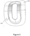
- Figure 3 depicts the EM flowmeter with the proposed compound coil configuration.
- a first coil 230 or the outer coil and enclosed within the first coil or outer coil 230 is the inner coil 240.
- the coils, first coil 230 and second coil 240 are arranged in a concentric manner comprised within a single unit of compound coil.
- the longer sides of the coils are close to each other.
- the shorter sides have sufficient gap for the electrodes to be installed.
- the electrodes are arranged in the gap between the first coil and the second coil as depicted in Figure 1 .
- the electrodes are arranged linearly at a position above the central diameter of the conduit 220.
- the electromagnetic flowmeter are provided with suitable power source and electronics circuitries for exciting the coils for producing electromagnetic fields for making potential difference measurements and display/transmitting the measured values.
- the electromagnetic flowmeter can comprise a display for indicating the determined flow of fluid in the flow pipe.
- the electromagnetic flowmeter wherein the determined flow of fluid in the flow pipe (measured potential difference between the electrodes) is transmitted to a remote control center of the electromagnetic flowmeter for further analysis.
- the electromagnetic flowmeter is Internet of Things (IOT) enabled for providing remote controlling, better visibility of the working of the electromagnetic flowmeter, providing real time information to software systems and other surrounding IOT enabled systems.
- IOT Internet of Things
- the electromagnetic flowmeter described herein above comprises a processing device, an excitation unit, potential sensing electrodes, coils and a flow pipe or conduit through which fluids to be measured flow.
- the excitation unit is controlled by the processing device wherein the processing device is used for taking measurements from potential sensing electrodes.
- the coils are excited by the excitation unit wherein the power of excitation is controlled by the processing device. It may be known to the person skilled in the art that the processing device can internally calibrate the rate of flow of the fluid corresponding to the measured potential difference and results can be displayed or transmitted to a remote control centre for further analysis.
Description
- The present invention relates generally to an electromagnetic flowmeter for measuring flow of fluid and more particularly to a compact electromagnetic flowmeter.
- Measurement of flow of fluids through a conduit or pipe can be done by numerous ways like using electromagnetic flowmeters. A typical electromagnetic flowmeter works on Faraday's law of electromagnetic induction. An electromagnetic field is imposed within a flow pipe having a flow of fluid with a certain level of conductivity. Electromotive force (EMF) induced as a result of the interaction of the electromagnetic field with fluid molecules (ions in the fluid), is measured using electrodes provided at the pipe side walls. The measured EMF is proportional to the flowrate and thus used to measure flowrate. While electromagnetic flowmeters are attractive given that they have high accuracy and simplistic in construction, it is desirable to reduce the material cost and/or weight of the flowmeters and provide for a more compact electromagnetic flowmeter with minimal impact on signal strength.
- The imposition of magnetic field is done using copper coils by electrically exciting the copper coils. The sensitivity of the electromagnetic flowmeter is directly influenced by placement of these copper coils and inserts. Also, the shape of coils play an important role in the performance (e.g. sensitivity, accuracy, linearity) of the electromagnetic flow meter. Most electromagnetic flowmeters conventionally use saddle shaped coils for magnetic field generation. These coils, whatever be the shape, needs to be mounted on the surface within the electromagnetic flowmeter and be closer to the fluid passing through the electromagnetic flowmeter.
- Conventionally, two electromagnetic coils of the same dimensions, shape and size are provided, one each at the top and bottom of a liner or insulating pipe that carries the fluid that is to be measured. A pair of electrodes are inserted at the sides of the liner to measure the signal generated and on the basis of the measured signal the flow rate of the fluid is measured. Due to provision of two coils one on top and another at the bottom of the liner the signal strength is adequate for measurement purposes. In case a single coil is used instead of two coils, the cost is reduced due to reduction of material however the signal strength and compactness of the electromagnetic flowmeter is compromised. Other configurations relating to use of coils can also be interesting to provide cost effective, compact packaging of coils in an electromagnetic flowmeter. Such configurations in a compact electromagnetic flowmeter need to provide for an optimal signal strength with reduced usage of material for the coils.
-
US 2016/0061856 A1 discloses an electromagnetic boat speedometer including a boundary layer velocity compensating arrangement comprising a primary coil for producing a primary electromagnetic field within a relatively large first volume of water, and a secondary coil.GB 990,484 WO 2012/083745A1 discloses an electromagnetic flow meter sensor capable of detecting a magnetic field and magnetic permeability. - The above-mentioned shortcomings, disadvantages and problems are addressed herein which will be understood by reading and understanding the following specification.
- The invention is defined by the appended claims.
-
-
Figure 1 depicts a typical electromagnetic flowmeter. -
Figure 2 depicts an electromagnetic flowmeter in accordance with an embodiment of the present invention. -
Figure 3 depicts a front view of the coils of the electromagnetic flowmeter. - The present invention provides an electromagnetic flowmeter for measuring flow of fluid and more particularly provides for a more compact electromagnetic flowmeter. It also provides for a coil configuration where two or more coils (a set of coil) can be placed together sharing a surface area in a single location instead of being spread across different locations i.e. the coils are not placed on top and bottom side/portion of the conduit. More than one set of coils, however can be used to create further configurations depending on signal strength requirement to interact with the fluid flow or for detecting certain characteristics of fluid such as multiphase fluid flow or complete filling of fluid conduit or for improved accuracy and sensitivity.
- As mentioned earlier, coils are used for inducing an electromagnetic field which in turn leads to measurement of flowrate of fluid passing through a conduit or flow pipe of the electromagnetic flowmeter. These coils which are usually in set of two coils, where each coil is mounted on top of the liner and bottom of the liner that carries the fluid can influence performance and sensitivity of the electromagnetic flowmeter as inducing a strong electromagnetic field for accurate results is dependent on both these coils. However having two coils of the same dimension in an electromagnetic flowmeter can affect the compactness as well as cost of the electromagnetic flowmeter. In order to achieve same level of performance as with having two coils of same dimension the present invention provides for an alternative arrangement of the coils.
- In the following detailed description, reference is made to the accompanying drawings that form a part hereof, and in which is shown by way of illustration specific embodiments, which may be practiced. These embodiments are described in sufficient detail to enable those skilled in the art to practice the embodiments, and it is to be understood that other embodiments may be utilized. The following detailed description is, therefore, not to be taken in a limiting sense.
-
Figure 1 shows anelectromagnetic flowmeter 100 for measuring flow of fluid flowing in aconduit 110. Electromagnetic flowmeters can measure flowrate for fluids with some amount of conductivity. As shown inFigure 1 , theelectromagnetic flowmeter 100 is provided with a set of coils, afirst coil 120 and asecond coil 130 mounted onto a conduit lined by an insulating liner carrying the fluid for measurement by the electromagnetic flowmeter. The coils of an electromagnetic flowmeter are electrically excited for generation of an electromagnetic field by an excitation unit, so that the electromagnetic filed interacts with the fluid passing through theconduit 100. -
Figure 1 shows anelectrode 140 mounted on theconduit 110 for measuring potential difference generated by the interaction of electromagnetic field in the fluid.Figure 1 only shows one of theelectrodes 140 from a pair of electrodes wherein the other electrode is present on the opposite side of the conduit (not shown). The potential difference measured by the pair ofelectrodes 140 eventually determines the rate of flow of fluid in theelectromagnetic flowmeter 100. -
Figure 2 shows anelectromagnetic flowmeter 200 in accordance to an embodiment of the present invention wherein asingle coil 210 in a compounded manner is depicted. As shown inFigure 2 , instead of two coils of a typical electromagnetic flowmeter as shown inFigure 1 asingle compound coil 210 is provided. Thesingle compound coil 210 is comprising two coils mounted on a surface ofconduit 220 and excited by an excitation unit (not shown) for generating an electromagnetic field. Here, the first coil (outer coil) is placed such that its inner edge is adjacent to the outer edge of the second coil i.e. the second coil lies inside the first coil. The coils can be electrically connected to be in series to each other or in parallel to each other. A first coil 230 (outer coil) is concentrically positioned with a second coil 240 (inner coil) and thesecond coil 240 is placed within the surface area enclosed by thefirst coil 230. The electrode 140 (one electrode) is shown to be positioned in between thefirst coil 230 and thesecond coil 240, the other electrode (not shown in figure) is also positioned accordingly on the side not visible in the figure. - In an embodiment of the present invention the coils, i.e., the
first coil 230 and thesecond coil 240 are arranged such a way that the overall performance of the electromagnetic flowmeter is unaffected (minimal change in performance). There is a resultant reduction in usage of material for the coils like copper and the signal strength is almost unaffected. -
Figure 3 depicts the EM flowmeter with the proposed compound coil configuration. As mentioned above there is afirst coil 230 or the outer coil and enclosed within the first coil orouter coil 230 is theinner coil 240. The coils,first coil 230 andsecond coil 240 are arranged in a concentric manner comprised within a single unit of compound coil. The longer sides of the coils are close to each other. However, the shorter sides (towards the pipe extremes), have sufficient gap for the electrodes to be installed. Hence the electrodes are arranged in the gap between the first coil and the second coil as depicted inFigure 1 . Hence the electrodes are arranged linearly at a position above the central diameter of theconduit 220. Such a configuration results in saving coil material compared with that in the double coil configuration (as shown inFigure 1 ). At the same time decrease in signal strength or performance level is negligible. It is to be noted that the shape of the coil can be different from that shown in the figures. - The electromagnetic flowmeter are provided with suitable power source and electronics circuitries for exciting the coils for producing electromagnetic fields for making potential difference measurements and display/transmitting the measured values. In an embodiment, the electromagnetic flowmeter can comprise a display for indicating the determined flow of fluid in the flow pipe.
- In an embodiment, the electromagnetic flowmeter wherein the determined flow of fluid in the flow pipe (measured potential difference between the electrodes) is transmitted to a remote control center of the electromagnetic flowmeter for further analysis.
- In an embodiment, the electromagnetic flowmeter is Internet of Things (IOT) enabled for providing remote controlling, better visibility of the working of the electromagnetic flowmeter, providing real time information to software systems and other surrounding IOT enabled systems.
- The electromagnetic flowmeter described herein above comprises a processing device, an excitation unit, potential sensing electrodes, coils and a flow pipe or conduit through which fluids to be measured flow. The excitation unit is controlled by the processing device wherein the processing device is used for taking measurements from potential sensing electrodes. The coils are excited by the excitation unit wherein the power of excitation is controlled by the processing device. It may be known to the person skilled in the art that the processing device can internally calibrate the rate of flow of the fluid corresponding to the measured potential difference and results can be displayed or transmitted to a remote control centre for further analysis.
- This written description uses examples to describe the subject matter herein, including the best mode, and also to enable any person skilled in the art to make and use the subject matter. The patentable scope of the subject matter is defined by the claims, and may include other examples that occur to those skilled in the art. Such other examples are intended to be within the scope of the claims if they have structural elements that do not differ from the literal language of the claims, or if they include equivalent structural elements with insubstantial differences from the literal language of the claims.
Claims (4)
- An electromagnetic flowmeter (200) for measuring flow of fluid flowing in a conduit (220) of the electromagnetic flowmeter (200), wherein the electromagnetic flowmeter (200) comprises:a pair of electrodes (140) mounted on the conduit (220) for measuring potential difference generated by the interaction of an electromagnetic field in the fluid to determine the flow of fluid in the electromagnetic flowmeter (200);a processing unit, wherein the processing unit acquires signals from the pair of electrodes (140) and processes the signal for measurement;at least one set of coils (210) comprising at least two coils mounted on a surface of the conduit (220) and excited by an excitation unit for generating the electromagnetic field;wherein a first coil (230) from the at least one set of coils is concentrically positioned with a second coil (240) from the set of coil, and the second coil (240) is placed within the enclosed surface area of the first coil (230), characterised in that the electrodes are arranged in a gap between the shorter side of the first coil (230) and the shorter side of the second coil (240) and arranged linearly at a position above the central diameter of the conduit (220).
- The electromagnetic flowmeter (200) as claimed in claim 1, further comprising an excitation unit to excite the at least one set of coils (210) for generating the electromagnetic field that interacts with the fluid passing through the electromagnetic flowmeter (200), wherein the excitation unit is controlled by the processing unit.
- The electromagnetic flowmeter (200) as claimed in any of the preceding claims, further comprising a display for indicating the measured flow rate of fluid.
- The electromagnetic flowmeter (200) as claimed in any of the preceding claims, wherein measured flow rate of fluid is transmitted to a remote control centre of the electromagnetic flowmeter (200) for storage or analysis.
Applications Claiming Priority (2)
| Application Number | Priority Date | Filing Date | Title |
|---|---|---|---|
| IN201841007563 | 2018-02-28 | ||
| PCT/IB2019/051280 WO2019166908A1 (en) | 2018-02-28 | 2019-02-18 | An electromagnetic flowmeter |
Publications (2)
| Publication Number | Publication Date |
|---|---|
| EP3759441A1 EP3759441A1 (en) | 2021-01-06 |
| EP3759441B1 true EP3759441B1 (en) | 2023-06-14 |
Family
ID=65812357
Family Applications (1)
| Application Number | Title | Priority Date | Filing Date |
|---|---|---|---|
| EP19711705.4A Active EP3759441B1 (en) | 2018-02-28 | 2019-02-18 | An electromagnetic flowmeter |
Country Status (4)
| Country | Link |
|---|---|
| US (1) | US11486748B2 (en) |
| EP (1) | EP3759441B1 (en) |
| CN (1) | CN111771104B (en) |
| WO (1) | WO2019166908A1 (en) |
Family Cites Families (14)
| Publication number | Priority date | Publication date | Assignee | Title |
|---|---|---|---|---|
| GB990484A (en) * | 1962-08-10 | 1965-04-28 | Mawdsley S Ltd | Improvements in or relating to electromagnetic flowmeters |
| GB1206463A (en) | 1967-02-09 | 1970-09-23 | Kent Ltd G | Improvements in or relating to fluid flow velocity measurement |
| GB2324606B (en) * | 1997-04-25 | 2002-01-16 | Kent Meters Ltd | Electromagnetic flowmeter |
| US6634238B2 (en) * | 2001-07-09 | 2003-10-21 | Endress + Hauser Flowtec Ag | Method of operating an electromagnetic flowmeter |
| JP2004012308A (en) * | 2002-06-07 | 2004-01-15 | Smc Corp | Position measuring device utilizing coil, float type flowmeter, and method of measuring position |
| US7779702B2 (en) | 2008-11-03 | 2010-08-24 | Rosemount Inc. | Flow disturbance compensation for magnetic flowmeter |
| CN101699226B (en) * | 2009-11-02 | 2012-03-21 | 北京航空航天大学 | Electromagnetic flowmeter for non-full pipe flow measurement |
| CN201964914U (en) * | 2010-12-22 | 2011-09-07 | 上海威尔泰工业自动化股份有限公司 | Electromagnetic flow meter sensor capable of detecting magnetic field and magnetic permeability |
| CN203573793U (en) * | 2013-07-03 | 2014-04-30 | 艾默生过程控制流量技术有限公司 | Coil assembly, electromagnetic flowmeter, field instrument, and voltage transformation equipment |
| US9983223B2 (en) * | 2014-08-26 | 2018-05-29 | Brickhouse Innovations, Llc | Electromagnetic boat speedometer having boundary layer velocity compensation |
| CN204694303U (en) * | 2015-03-11 | 2015-10-07 | 艾默生过程控制流量技术有限公司 | Electromagnetic flowmeter |
| GB2544286A (en) * | 2015-11-10 | 2017-05-17 | Abb Ltd | Method and apparatus for electrode impedance measurement |
| US9784603B2 (en) * | 2016-02-17 | 2017-10-10 | Invensys Systems, Inc. | Electromagnetic flowmeter empty pipe detection system |
| US10024707B2 (en) * | 2016-02-17 | 2018-07-17 | Schneider Electric Systems Usa, Inc. | Electromagnetic flowmeter calibration verification |
-
2019
- 2019-02-18 CN CN201980016136.2A patent/CN111771104B/en active Active
- 2019-02-18 EP EP19711705.4A patent/EP3759441B1/en active Active
- 2019-02-18 US US16/976,605 patent/US11486748B2/en active Active
- 2019-02-18 WO PCT/IB2019/051280 patent/WO2019166908A1/en unknown
Also Published As
| Publication number | Publication date |
|---|---|
| CN111771104A (en) | 2020-10-13 |
| CN111771104B (en) | 2023-03-10 |
| US11486748B2 (en) | 2022-11-01 |
| EP3759441A1 (en) | 2021-01-06 |
| US20210010838A1 (en) | 2021-01-14 |
| WO2019166908A1 (en) | 2019-09-06 |
Similar Documents
| Publication | Publication Date | Title |
|---|---|---|
| JP5097855B2 (en) | Speed enhancement flow measurement | |
| US7946184B2 (en) | Electromagnetic flowmeter having temperature measurement value for correcting electrical conductivity value | |
| US4513624A (en) | Capacitively-coupled magnetic flowmeter | |
| JPH0394121A (en) | Electromagnetic flow meter | |
| JP2007531893A (en) | Scaleable averaging insertion vortex flowmeter | |
| US9851242B2 (en) | Collocated sensor for a vibrating fluid meter | |
| US4622202A (en) | Reactor in-vessel sensor and core monitoring apparatus | |
| CN100414260C (en) | Vortex flow sensor | |
| WO2005059476A3 (en) | Tunable empty pipe function | |
| JP2005308740A (en) | Magneto-dielectric flow measuring method and magneto-dielectric flowmeter | |
| EP2034280B1 (en) | Coriolis flow meter with at least three sensors | |
| US3372589A (en) | Side-saddle magnetic flowmeter | |
| JP2003532885A (en) | Flowmeter | |
| US5426983A (en) | Flow meter | |
| EP3759441B1 (en) | An electromagnetic flowmeter | |
| CN105509824A (en) | Permanent-magnetic liquid metal flowmeter | |
| US4122714A (en) | Magnetic current meter for open channel flow measurement | |
| CN205373787U (en) | Magneto liquid metal flowmeter | |
| WO2018109675A1 (en) | An electromagnetic flowmeter | |
| CN208606821U (en) | Anti-tampering New Electromagnetic Flowmeter | |
| CN105841760A (en) | Insert-type electromagnetic flowmeter | |
| WO2018193294A1 (en) | An electromagnetic flowmeter | |
| WO2018100447A1 (en) | An attachable electromagnetic flowmeter | |
| CN217374974U (en) | Novel quantitative filling electromagnetic flowmeter | |
| CN110081940A (en) | A kind of high-precision electromagnetism water meter |
Legal Events
| Date | Code | Title | Description |
|---|---|---|---|
| STAA | Information on the status of an ep patent application or granted ep patent |
Free format text: STATUS: UNKNOWN |
|
| STAA | Information on the status of an ep patent application or granted ep patent |
Free format text: STATUS: THE INTERNATIONAL PUBLICATION HAS BEEN MADE |
|
| PUAI | Public reference made under article 153(3) epc to a published international application that has entered the european phase |
Free format text: ORIGINAL CODE: 0009012 |
|
| STAA | Information on the status of an ep patent application or granted ep patent |
Free format text: STATUS: REQUEST FOR EXAMINATION WAS MADE |
|
| 17P | Request for examination filed |
Effective date: 20200826 |
|
| AK | Designated contracting states |
Kind code of ref document: A1 Designated state(s): AL AT BE BG CH CY CZ DE DK EE ES FI FR GB GR HR HU IE IS IT LI LT LU LV MC MK MT NL NO PL PT RO RS SE SI SK SM TR |
|
| AX | Request for extension of the european patent |
Extension state: BA ME |
|
| DAV | Request for validation of the european patent (deleted) | ||
| DAX | Request for extension of the european patent (deleted) | ||
| GRAP | Despatch of communication of intention to grant a patent |
Free format text: ORIGINAL CODE: EPIDOSNIGR1 |
|
| STAA | Information on the status of an ep patent application or granted ep patent |
Free format text: STATUS: GRANT OF PATENT IS INTENDED |
|
| INTG | Intention to grant announced |
Effective date: 20230119 |
|
| GRAS | Grant fee paid |
Free format text: ORIGINAL CODE: EPIDOSNIGR3 |
|
| GRAA | (expected) grant |
Free format text: ORIGINAL CODE: 0009210 |
|
| STAA | Information on the status of an ep patent application or granted ep patent |
Free format text: STATUS: THE PATENT HAS BEEN GRANTED |
|
| AK | Designated contracting states |
Kind code of ref document: B1 Designated state(s): AL AT BE BG CH CY CZ DE DK EE ES FI FR GB GR HR HU IE IS IT LI LT LU LV MC MK MT NL NO PL PT RO RS SE SI SK SM TR |
|
| REG | Reference to a national code |
Ref country code: CH Ref legal event code: EP |
|
| REG | Reference to a national code |
Ref country code: DE Ref legal event code: R096 Ref document number: 602019030993 Country of ref document: DE |
|
| REG | Reference to a national code |
Ref country code: AT Ref legal event code: REF Ref document number: 1579536 Country of ref document: AT Kind code of ref document: T Effective date: 20230715 |
|
| REG | Reference to a national code |
Ref country code: LT Ref legal event code: MG9D |
|
| REG | Reference to a national code |
Ref country code: NL Ref legal event code: MP Effective date: 20230614 |
|
| PG25 | Lapsed in a contracting state [announced via postgrant information from national office to epo] |
Ref country code: SE Free format text: LAPSE BECAUSE OF FAILURE TO SUBMIT A TRANSLATION OF THE DESCRIPTION OR TO PAY THE FEE WITHIN THE PRESCRIBED TIME-LIMIT Effective date: 20230614 Ref country code: NO Free format text: LAPSE BECAUSE OF FAILURE TO SUBMIT A TRANSLATION OF THE DESCRIPTION OR TO PAY THE FEE WITHIN THE PRESCRIBED TIME-LIMIT Effective date: 20230914 Ref country code: ES Free format text: LAPSE BECAUSE OF FAILURE TO SUBMIT A TRANSLATION OF THE DESCRIPTION OR TO PAY THE FEE WITHIN THE PRESCRIBED TIME-LIMIT Effective date: 20230614 |
|
| REG | Reference to a national code |
Ref country code: AT Ref legal event code: MK05 Ref document number: 1579536 Country of ref document: AT Kind code of ref document: T Effective date: 20230614 |
|
| PG25 | Lapsed in a contracting state [announced via postgrant information from national office to epo] |
Ref country code: RS Free format text: LAPSE BECAUSE OF FAILURE TO SUBMIT A TRANSLATION OF THE DESCRIPTION OR TO PAY THE FEE WITHIN THE PRESCRIBED TIME-LIMIT Effective date: 20230614 Ref country code: NL Free format text: LAPSE BECAUSE OF FAILURE TO SUBMIT A TRANSLATION OF THE DESCRIPTION OR TO PAY THE FEE WITHIN THE PRESCRIBED TIME-LIMIT Effective date: 20230614 Ref country code: LV Free format text: LAPSE BECAUSE OF FAILURE TO SUBMIT A TRANSLATION OF THE DESCRIPTION OR TO PAY THE FEE WITHIN THE PRESCRIBED TIME-LIMIT Effective date: 20230614 Ref country code: LT Free format text: LAPSE BECAUSE OF FAILURE TO SUBMIT A TRANSLATION OF THE DESCRIPTION OR TO PAY THE FEE WITHIN THE PRESCRIBED TIME-LIMIT Effective date: 20230614 Ref country code: HR Free format text: LAPSE BECAUSE OF FAILURE TO SUBMIT A TRANSLATION OF THE DESCRIPTION OR TO PAY THE FEE WITHIN THE PRESCRIBED TIME-LIMIT Effective date: 20230614 Ref country code: GR Free format text: LAPSE BECAUSE OF FAILURE TO SUBMIT A TRANSLATION OF THE DESCRIPTION OR TO PAY THE FEE WITHIN THE PRESCRIBED TIME-LIMIT Effective date: 20230915 |
|
| PG25 | Lapsed in a contracting state [announced via postgrant information from national office to epo] |
Ref country code: FI Free format text: LAPSE BECAUSE OF FAILURE TO SUBMIT A TRANSLATION OF THE DESCRIPTION OR TO PAY THE FEE WITHIN THE PRESCRIBED TIME-LIMIT Effective date: 20230614 |
|
| PG25 | Lapsed in a contracting state [announced via postgrant information from national office to epo] |
Ref country code: SK Free format text: LAPSE BECAUSE OF FAILURE TO SUBMIT A TRANSLATION OF THE DESCRIPTION OR TO PAY THE FEE WITHIN THE PRESCRIBED TIME-LIMIT Effective date: 20230614 |
|
| PG25 | Lapsed in a contracting state [announced via postgrant information from national office to epo] |
Ref country code: IS Free format text: LAPSE BECAUSE OF FAILURE TO SUBMIT A TRANSLATION OF THE DESCRIPTION OR TO PAY THE FEE WITHIN THE PRESCRIBED TIME-LIMIT Effective date: 20231014 |
|
| PG25 | Lapsed in a contracting state [announced via postgrant information from national office to epo] |
Ref country code: SM Free format text: LAPSE BECAUSE OF FAILURE TO SUBMIT A TRANSLATION OF THE DESCRIPTION OR TO PAY THE FEE WITHIN THE PRESCRIBED TIME-LIMIT Effective date: 20230614 Ref country code: SK Free format text: LAPSE BECAUSE OF FAILURE TO SUBMIT A TRANSLATION OF THE DESCRIPTION OR TO PAY THE FEE WITHIN THE PRESCRIBED TIME-LIMIT Effective date: 20230614 Ref country code: RO Free format text: LAPSE BECAUSE OF FAILURE TO SUBMIT A TRANSLATION OF THE DESCRIPTION OR TO PAY THE FEE WITHIN THE PRESCRIBED TIME-LIMIT Effective date: 20230614 Ref country code: PT Free format text: LAPSE BECAUSE OF FAILURE TO SUBMIT A TRANSLATION OF THE DESCRIPTION OR TO PAY THE FEE WITHIN THE PRESCRIBED TIME-LIMIT Effective date: 20231016 Ref country code: IS Free format text: LAPSE BECAUSE OF FAILURE TO SUBMIT A TRANSLATION OF THE DESCRIPTION OR TO PAY THE FEE WITHIN THE PRESCRIBED TIME-LIMIT Effective date: 20231014 Ref country code: EE Free format text: LAPSE BECAUSE OF FAILURE TO SUBMIT A TRANSLATION OF THE DESCRIPTION OR TO PAY THE FEE WITHIN THE PRESCRIBED TIME-LIMIT Effective date: 20230614 Ref country code: CZ Free format text: LAPSE BECAUSE OF FAILURE TO SUBMIT A TRANSLATION OF THE DESCRIPTION OR TO PAY THE FEE WITHIN THE PRESCRIBED TIME-LIMIT Effective date: 20230614 Ref country code: AT Free format text: LAPSE BECAUSE OF FAILURE TO SUBMIT A TRANSLATION OF THE DESCRIPTION OR TO PAY THE FEE WITHIN THE PRESCRIBED TIME-LIMIT Effective date: 20230614 |
|
| PG25 | Lapsed in a contracting state [announced via postgrant information from national office to epo] |
Ref country code: PL Free format text: LAPSE BECAUSE OF FAILURE TO SUBMIT A TRANSLATION OF THE DESCRIPTION OR TO PAY THE FEE WITHIN THE PRESCRIBED TIME-LIMIT Effective date: 20230614 |