EP3758644B1 - Zahnmedizinisches pulverstrahlgerät - Google Patents
Zahnmedizinisches pulverstrahlgerät Download PDFInfo
- Publication number
- EP3758644B1 EP3758644B1 EP19706721.8A EP19706721A EP3758644B1 EP 3758644 B1 EP3758644 B1 EP 3758644B1 EP 19706721 A EP19706721 A EP 19706721A EP 3758644 B1 EP3758644 B1 EP 3758644B1
- Authority
- EP
- European Patent Office
- Prior art keywords
- line arrangement
- powder
- jet device
- nozzle
- fluid
- Prior art date
- Legal status (The legal status is an assumption and is not a legal conclusion. Google has not performed a legal analysis and makes no representation as to the accuracy of the status listed.)
- Active
Links
Images


Classifications
-
- A—HUMAN NECESSITIES
- A61—MEDICAL OR VETERINARY SCIENCE; HYGIENE
- A61C—DENTISTRY; APPARATUS OR METHODS FOR ORAL OR DENTAL HYGIENE
- A61C3/00—Dental tools or instruments
- A61C3/02—Tooth drilling or cutting instruments; Instruments acting like a sandblast machine
- A61C3/025—Instruments acting like a sandblast machine, e.g. for cleaning, polishing or cutting teeth
Definitions
- the invention relates to a dental powder jet device with a container for an abrasive powder, a nozzle and a first line arrangement which extends from a connection of the powder jet device through the container to the nozzle and is designed to guide a mixture formed from the powder and a first fluid made available to the powder jet device to the nozzle.
- Such a powder jet device in the form of a dental handpiece is known from the prior art.
- the powder jet device is used, for example, to remove dental plaque.
- the first fluid here in the form of compressed air, can be introduced into the container; this compressed air is then mixed with the powder in the container, so that a powder-air mixture is created.
- the latter is then passed on to the nozzle via the first line arrangement and - together with water - released to the outside via the nozzle under excess pressure, for example onto a tooth surface to be cleaned.
- the treatment of the tooth area to be cleaned with the powder jet device is usually repeatedly interrupted and the tooth area is cleaned of powder or plaque using a so-called air-water syringe.
- the practitioner must put the powder jet device aside and use the air-water syringe. This process is time-consuming and interrupts the workflow in an undesirable way.
- a dental powder jet device which uses water and compressed air as input medium and provides air or an air-powder mixture to a handpiece connected to the device.
- the Mixing of powder and air takes place outside the handpiece.
- the compressed air supplied to the device on the input side is split into two sub-lines at a branching point, with one line leading directly to a connection for the handpiece.
- the other sub-line is routed over the powder container and is used to form an air-powder mixture, which is optionally made available to the handpiece via a valve block.
- compressed air is constantly transmitted to the handpiece when it is active, and the air-powder mixture can be added optionally.
- the WO 02/074180 A1 a powder blasting device in which either air or an air-powder mixture can be supplied to a handpiece connected to the device via a foot control.
- An input-side supply block provides compressed air at a first connection, which is fed through a powder container, whereby it is possible to regulate this air using a hose pinch valve.
- so-called chip blower air is provided via a second connection, which is fed through a second line and flows into the line for the air-powder mixture.
- the two line arrangements are brought together in an area downstream of the powder container, but before an output-side connection for the actual handpiece.
- the US6,277,003B1 a powder jet device for dental purposes, where special measures are provided to introduce air into a powder container in such a way that the powder contained therein is swirled up as efficiently as possible.
- the container is also bridged using another compressed air line, with the second line flowing back into the first line section, which is intended for the air-powder mixture, in a so-called mixing chamber downstream of the powder container.
- a connection is then made to a handpiece, which is ultimately used to work on the surface to be treated.
- the US 4,540,365 A a system with a handheld device for tooth cleaning for delivering a jet loaded with abrasive material against a tooth to be cleaned.
- the system is designed for connection to sources of pressurized liquids and gases.
- the system also includes the handpiece with a container containing the abrasive material.
- the abrasive material is transported from the container into a mixing chamber within a nozzle on the handpiece through various valves on the handpiece, each of which controls a liquid or gas flow.
- the liquid or gas flows can be combined with the abrasive-loaded flow in the mixing chamber to create a homogeneous flow that is delivered to a single point on the tooth to be cleaned.
- the invention is based on the object of providing an improved powder jet device. In particular, it should enable easier handling when cleaning teeth.
- a dental powder jet device which has a container for an abrasive powder, a nozzle and a first line arrangement which extends from a connection of the powder jet device through the container to the nozzle and is designed to guide a mixture formed from the powder and a first fluid provided to the powder jet device to the nozzle. Furthermore, the powder jet device has a second line arrangement which extends from the connection of the powder jet device and which is designed to introduce a second similar fluid provided to the powder jet device into the first line arrangement at a point downstream of the container for the abrasive powder, wherein a valve for releasing and blocking the second line arrangement is arranged at the point at which the second line arrangement opens into the first line arrangement.
- This design makes it possible to deliver the second fluid to a treatment site without any powder mixed in.
- the treatment site can thus be cleaned with the powder jet device without the user of the powder jet device first having to change handheld devices.
- the work process is made easier in this way.
- the positioning of the valve according to the invention in the area where the second line arrangement joins the first line arrangement means that the second fluid can be directed specifically into the first line arrangement and a quick change between the media delivered by the device can take place. Furthermore, there is no risk of the abrasive powder accidentally penetrating areas of the second line arrangement.
- the powder jet device is designed as a hand-held device which has a handle part and a cannula containing the nozzle at the front end area, wherein the point at which the second line arrangement opens into the first line arrangement is formed in a transition area between the handle part and the cannula.
- the line arrangements are therefore brought together according to the invention in the hand-held device itself, resulting in a particularly simple and compact structure for the powder jet device.
- the valve is designed in such a way that the second line arrangement for the second fluid is conductively connected to the first line arrangement when there is a higher pressure in the second line arrangement than in the first line arrangement and that the second line arrangement for the second fluid is not conductively connected to the first line arrangement when there is a lower pressure in the second line arrangement than in the first line arrangement.
- the valve can thus be opened and closed in a controlled manner only via the pressure.
- the valve can be opened and closed in this way by appropriately regulating the pressure of the first fluid.
- the valve is designed like a sealing ring. In this way, the desired effect can be achieved in a particularly suitable manufacturing process.
- the first line arrangement has a first pipeline and the second line arrangement has a second pipeline which extends around the first pipeline, with both pipelines opening into a common chamber region which merges into an end section of the first line arrangement which extends to the nozzle, and with the valve being formed at an end region of the second pipeline.
- the sealing ring is arranged at the front end of the second pipeline and forms a valve lip which rests on the outer circumference of the first pipeline.
- means for releasing or blocking the section of the first line arrangement are arranged in a section of the first line arrangement upstream of the point. This makes it possible for the valve to be opened and closed by these means.
- the means for releasing or blocking the section of the first line arrangement are arranged upstream of the container. This allows the first fluid to be directed into the container in a targeted manner.
- the means for releasing or blocking the section of the first line arrangement are also designed for a throttled release of the section of the first line arrangement.
- the means for releasing or blocking the section of the first line arrangement are preferably coupled to an operating element, which can in particular be designed as a rotating ring.
- the powder jet device also has a third line arrangement which is designed to conduct water to the nozzle. This ensures that the mixture of the first fluid and the powder is mixed with the water in the area of the nozzle. It is preferably provided that the third line arrangement extends separately from the first and second line arrangement from the connection through the powder jet device to the nozzle. Furthermore, the powder jet device preferably also has means for releasing and blocking the third line arrangement. This preferably allows the water supply to be selectively switched on or off.
- the nozzle is preferably designed in such a way that the water in the area of the nozzle mixes with the mixture formed from the powder and the first fluid delivered via the first line arrangement. This ensures that the Usually water-soluble abrasive powders can be dissolved and removed by water immediately after the tooth surface has been treated.
- the means for releasing and blocking the section of the first line arrangement and the means for releasing and blocking the third line arrangement can be designed in dependence on one another in such a way that the third line arrangement is released when the section of the first line arrangement is released and that the third line arrangement is blocked when the section of the first line arrangement is blocked. In this way, the dispensing of the mixture of the first fluid and the powder and the dispensing of the water can be adjusted with particularly simple handling.
- the powder jet device also has means for releasing or blocking the second line arrangement. This allows the second fluid to be controlled in a targeted manner.
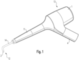
- Fig.1 shows a perspective sketch of a powder blasting device according to the application.
- the powder blasting device is particularly preferably designed - as shown - as a hand-held device. It has a handle part 11 for holding the powder blasting device during a powder blasting process.
- the powder blasting device is elongated overall, so that a front end region 12 can be distinguished from a rear end region 13.
- the powder blasting device has a container 1 for an abrasive powder, preferably at its rear end region 13. At its front end region 12, the powder jet device has a cannula 14 which has a nozzle 2 at its free end.
- the powder blasting device also has a connection 4 which - as shown in more detail below - is designed to conductively connect line arrangements formed in the powder blasting device to supply lines.
- the connection 4 can in particular be a coupling, for example a quick coupling, such as the so-called Multiflex coupling.
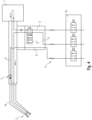
- Fig.2 shows a schematic diagram of the powder jet device.
- the powder jet device comprises a first line arrangement 3, which extends from the connection 4 through the container 1 to the nozzle 2.
- This line arrangement 3 is designed to guide a mixture formed from the powder and a first fluid provided to the powder jet device to the nozzle 2.
- the first fluid is, for example, a first air.
- the design of the powder jet device is preferably such that the first fluid is made available to the powder jet device under a first overpressure. can.
- the first overpressure can be between 2.5 bar and 3.5 bar, for example, so for example 3 bar.
- the design is such that the first fluid can be made available to the powder blasting device from a supply unit 10, in particular by means of a first supply line 21.
- the first supply line 21 can extend through a supply hose that extends between the supply unit 10 and the connection 4 of the powder blasting device.
- a dental arrangement according to the application comprises a powder jet device according to the application and the supply unit 10.
- the first fluid can be driven by the first overpressure and fed into the first line arrangement 3 via the connection 4, thus reaching the container 1 and mixing there with the powder in the container 1, so that the mixture mentioned, formed from the powder and the first fluid, is created.
- this mixture is then driven further through the first line arrangement 3 - still by increased pressure - and finally released to the outside via the nozzle 2 under overpressure, for example onto a tooth area to be cleaned.
- the powder jet device comprises a second line arrangement 5, which extends from the connection 4 and which is designed to introduce a second fluid provided to the powder jet device into the first line arrangement 3 at a location 6 downstream of the container 1.
- This location 6 or the mouth of the second line arrangement 5 into the first line arrangement 3 is therefore located between the container 1 and the nozzle 2.
- the point 6 or mouth can be formed, for example, in a transition region between the handle part 11 and the cannula 14.
- the design is such that the second fluid can be made available to the powder blasting device from the supply unit 10, in particular by means of a second supply line 22, which in turn can extend through the supply hose.
- the second fluid is preferably of the same type as the first fluid, for example also air.
- the second fluid can therefore be a second air.
- the design of the powder jet device is preferably such that the second fluid can be made available to the powder jet device under a second overpressure.
- the second overpressure can be between 0.5 bar and 1.5 bar, for example 1 bar.
- the second fluid can be driven by the second overpressure and introduced via the connection 4 into the second line arrangement 5, reaches the first line arrangement 3 at the point 6 and is finally discharged to the outside via the nozzle 2 under overpressure, for example onto the tooth area to be cleaned.
- the valve 7 is preferably formed in the region of the mouth or point 6.
- valve 7 is designed such that the second line arrangement 5 for the second fluid is conductively connected to the first line arrangement 3 when there is a higher pressure in the second line arrangement 5 than in the first line arrangement 3, in particular at the point 6, and that the second line arrangement 5 for the second fluid is not conductively connected to the first line arrangement 3 when there is a lower pressure in the second line arrangement 5 than in the first line arrangement 3, in particular at the point 6.
- the design can further be such that the valve 7 is closed when the same pressure prevails in the second line arrangement 5 as in the first line arrangement 3, in particular at the point 6.
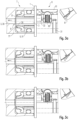
- Fig. 3a In the left-hand area, a longitudinal section of the area surrounding the valve 7 is schematically sketched.
- the valve 7 is shown in an open state; in the second line arrangement 5, a higher pressure prevails than at the point 6 adjacent to the valve 7 in the first line arrangement 3. This is the case, for example, if the first overpressure prevailing in the second line arrangement 5 is 1 bar and there is no overpressure at the point 6 of the first line arrangement 3.
- the first line arrangement 3 can have a first pipe 35, which extends in particular within the handle part 11.
- the second line arrangement 5 can have a second pipe 51, which extends around the first pipe 35, so that for the second fluid - viewed in normal cross-section - an annular flow area is formed, which is limited on the inside by the first pipe 35 and on the outside by the second pipe 51.
- This design is shown in the longitudinal section of the Fig. 3a indicated.
- the valve 7 is preferably formed at an end region of the second pipe 51, so that - under appropriate pressure conditions - it comes into sealing contact with the first pipe 35 from the outside and is thereby closed.
- the valve 7 When the valve 7 is open, the second fluid flows - as in Fig. 3a sketched - through the valve 7 and enters a chamber region 71; the latter merges into an end section 39 of the first line arrangement 3, which extends through the cannula 14 to the nozzle 2 and opens outwards there.
- the valve 7 can be designed in the manner of a sealing ring.
- the design is preferably such that a contact pressure with which the valve lip 77 formed by the sealing ring is pressed against the first pipeline 35 increases with increasing pressure in the first pipeline arrangement 3 at the mouth or point 6.
- the powder jet device preferably has in a section of the first line arrangement 3 upstream of point 6 - i.e. between point 6 and connection 4 - arranged means 8 for releasing and blocking the section of the first line arrangement 3.
- these means 8 for releasing and blocking the section of the first line arrangement 3 are arranged upstream of the container 1, i.e. between the connection 4 and the container 1.
- the means 8 for releasing and blocking the section of the first line arrangement 3 preferably comprise a directional valve with two connections and at least two switching positions.
- a first of the two connections is connected to a partial area 31 of the first line arrangement 3, which extends between the means 8 for releasing and blocking the section of the first line arrangement 3 and the connection 4 of the powder jet device.
- a second of the two connections is connected to a further partial area 32 of the first line arrangement 3, which extends between the means 8 for releasing and blocking the section of the first line arrangement 3 and the location 6 or the container 1.
- a first of the at least two switching positions is a release position in which the first partial region 31 is conductively connected to the further partial region 32
- a second of the at least two switching positions is a blocking position in which the first partial region 31 is not conductively connected to the further partial region 32.
- the means 8 for releasing and blocking the section of the first line arrangement 3 can be designed, for example, in the form of a rotary ring 81 of the powder blasting device that can be manipulated from the outside, whereby the directional control valve can be adjusted by rotating the rotary ring 81, i.e. can be brought into a desired switching position.
- the directional control valve can, for example, have a tappet 85 that is designed to block the relevant media path in the blocking position and to keep it open in the release position.
- Fig. 3a It is also indicated very schematically that the container 1 is located between the directional control valve and the valve 7.
- the directional control valve - as in the Figures 2 and 3a indicated - in the second switching position or in the blocking position, it can be achieved that there is no overpressure in the first line arrangement 3 at point 6. If in this case the second overpressure prevailing in the second line arrangement 5 is 1 bar, the valve 7 is opened and the second fluid flows into the first line arrangement 3 at point 6 and then outwards via the nozzle 2.
- the directional control valve - as in Fig. 3c indicated in an analogous manner - in the first switching position or in the release position it can be achieved that in the first line arrangement 3 at the point 6 there is a higher pressure - for example the aforementioned first overpressure of 3 bar - than in the second line arrangement 5. In this case, the valve 7 is therefore closed and the second fluid does not flow into the first line arrangement 3.
- the powder jet device preferably also comprises a third line arrangement 9, which extends from the connection 4 through the device to the nozzle 2 and is designed to guide water to the nozzle 2.
- the design of the nozzle 2 is preferably such that the water in the area of the nozzle 2 mixes with the mixture released via the first line arrangement 3, formed from the powder and the first fluid.
- the design is preferably such that the water can be made available to the powder jet device from the supply unit 10, in particular by means of a third supply line 23, which in turn can extend through the supply hose.
- the design of the powder jet device is preferably such that the water can be made available to the powder jet device under a third overpressure, in particular from the supply unit 10.
- the third line arrangement 9 up to the nozzle 2 is designed independently of the first line arrangement 3 and independently of the second line arrangement 5.
- the powder jet device can further comprise means (not shown in the figures) for releasing and blocking the third line arrangement 9. This makes it possible to switch the water supply to the nozzle 2 on or off.
- the supply unit 10 of the dental arrangement is accordingly designed to provide the powder jet device with the first fluid and the second fluid, in particular to provide the first fluid with the first overpressure and the second fluid with the second overpressure, wherein the second overpressure is lower than the first overpressure.
- the first overpressure is higher than 2 bar, preferably higher than 2.5 bar and the second overpressure is lower than 1.5 bar, preferably lower than 1 bar.
- the powder blasting device is suitable for the following three functions:
- a first function "tooth cleaning” the directional valve is located as in Fig. 3c sketched, in the release position.
- the first fluid is driven by the first overpressure through the connection 4 into the container 1, where the mixture is formed. Due to the pressure, the mixture is then conveyed further through the first line arrangement 3 and finally released to the outside via the nozzle 2.
- the part of the first line arrangement 3 that extends between the container 1 and the nozzle 2 can accordingly also be referred to as the "powder mixture channel”.
- the water is discharged via the third line arrangement 9 - driven by the third overpressure - via the nozzle 2.
- the discharge stream thus formed and discharged via the nozzle 2, consisting of the mixture and the water, is suitable for cleaning a tooth surface.
- valve 7 Since the valve 7 is closed, the mixture is prevented from flowing back into the second line arrangement 5. The second line arrangement 5 is relieved by the valve 7.
- the directional control valve For a second function "cleaning" the directional control valve is located as in Fig. 3a sketched, in the blocking position.
- the first line arrangement 3 is depressurized from the directional valve onwards. No powder or mixture formed from the powder and the first fluid is conveyed.
- the second fluid is conveyed through the second line arrangement 5 driven by the second overpressure.
- the valve 7 is opened due to the pressure conditions, so that the second fluid flows into the first line arrangement 3 at point 6 and is then discharged via the nozzle 2.
- the water is driven by the third overpressure and is conveyed through the third line arrangement 9 and released via the nozzle 2.
- the water and the second fluid combine at the nozzle 2 to form a "cleaning spray".
- the tooth surface can be cleaned with this cleaning spray.
- the tooth surface can be a cavity, for example.
- particles of the powder that may still be in the first line arrangement 3 in the "powder mixing channel” can be blown out by the second fluid.
- the directional control valve is located as in Fig. 3a outlined, in the blocking position.
- the means for releasing and blocking the third line arrangement 9 are in the blocking position so that no water is directed to the nozzle 2.
- the second fluid is driven by the second overpressure and is conveyed through the second line arrangement 5.
- the valve 7 is opened due to the pressure conditions, so that the second fluid flows into the first line arrangement 3 at the point 6 and is then discharged via the nozzle 2.
- the powder mixing channel can be blown free, especially in the area of the cannula 14.
- This function can be achieved, for example, by a "permanent" or time-controlled or separate connection of the second fluid.
- the handpiece is located in a tray of the dental device to carry out this function.
- the means 8 for releasing and blocking the section of the first line arrangement 3 can also be designed for a throttled release of the section of the first line arrangement 3.
- the directional control valve can have a corresponding third switching position, which is a throttle position.
- Fig. 3b A corresponding case is outlined in which the directional control valve is in the throttle position.
- the design can be such that in the throttle position the pressure prevailing in the first line arrangement 3 at point 6 is greater than the pressure prevailing in the second line arrangement 5, so that the valve 7 is closed.
- the first "tooth cleaning" function can be carried out, whereby the mixture is delivered via the nozzle 2 at a reduced pressure compared to the situation in which the directional control valve is in the above-mentioned release position.
- the means 8 for releasing and blocking the section of the first line arrangement 3 and the means for releasing and blocking the third line arrangement 9 can be designed in dependence on one another such that the third line arrangement 9 is released when the section of the first line arrangement 3 is released and that the third line arrangement 9 is blocked when the section of the first line arrangement 3 is blocked.
- the directional control valve in this design can have four connections, as in Fig.4 outlined and at least two switching positions, the first switching position being a release position in which both the first sub-area 31 is conductively connected to the second sub-area 32 and the third line arrangement 9 is also enabled.
- the second switching position is a blocking position in which the first sub-area 31 is not conductively connected to the second sub-area 32 and the third line arrangement 9 is also blocked.
- This design allows for simplified handling.
- the directional control valve of this design is in the blocking position, the working area can be dried and blown clean by releasing the second fluid.
- the directional control valve can - as in Fig.4 indicated - have a throttle position in which preferably the first line arrangement 3 is throttled, but the third line arrangement 9 is not throttled.
- means for releasing or blocking the second line arrangement 5 can also be provided.
- the supply of the second fluid to the nozzle 2 can be blocked in particular in a case in which the first line arrangement 3 is also blocked by the means 8. For example, only water can be dispensed via the nozzle 2.
- the design can also be such that the three media mentioned - first fluid, second fluid and water - can be switched on and off independently of one another.
- the powder jet device can accordingly have three independently switchable valve arrangements (not shown in the figures).
- the powder blasting device does not have a manually switchable valve arrangement in the three line arrangements 3, 5, 9 mentioned.
- Three switchable valve arrangements can be formed in the supply unit 10, by means of which the three corresponding supply lines 21, 22, 23 can be released and blocked.
- the valve arrangements of the supply unit 10 can be designed to be adjustable, for example, using buttons or switches, in particular foot switches.
- a corresponding programmable control can also be provided in software.
- a control valve in the hand-held device is not required in this case.
- the design of the line arrangements 3, 5, 9 can be as shown in the figures with the usual symbols; in particular, it can be provided that the line arrangements 3, 5, 9 only have the valve arrangements shown, but no further valve arrangements or other elements for influencing a corresponding fluid or water flow.
- Fig.5 The design shown is suitable both for handpieces with a quick coupling, for example with the Multiflex coupling mentioned, and for so-called fixed connection instruments, in which a supply hose between the supply unit 10 and the hand instrument is not connected to the latter via a quick coupling, but via a screw connection.
Landscapes
- Health & Medical Sciences (AREA)
- Oral & Maxillofacial Surgery (AREA)
- Dentistry (AREA)
- Epidemiology (AREA)
- Life Sciences & Earth Sciences (AREA)
- Animal Behavior & Ethology (AREA)
- General Health & Medical Sciences (AREA)
- Public Health (AREA)
- Veterinary Medicine (AREA)
- Dental Tools And Instruments Or Auxiliary Dental Instruments (AREA)
Description
- Die Erfindung betrifft ein zahnmedizinisches Pulverstrahlgerät mit einem Behälter für ein abrasives Pulver, einer Düse und einer ersten Leitungsanordnung, die sich von einem Anschluss des Pulverstrahlgeräts durch den Behälter zu der Düse erstreckt und dazu ausgebildet ist, eine Mischung, gebildet aus dem Pulver und einem, dem Pulverstrahlgerät zur Verfügung gestellten ersten Fluid zu der Düse zu leiten.
- Aus dem Stand der Technik ist ein solches Pulverstrahlgerät in Form eines zahnärztlichen Handstücks bekannt. Das Pulverstrahlgerät dient beispielsweise zum Entfernen von Zahnbelägen. In den Behälter kann das erste Fluid, hier in Form einer Druckluft eingeleitet werden; im Behälter wird dann diese Druckluft mit dem Pulver vermischt, so dass ein Pulver-Luft-Gemisch entsteht. Letzteres wird dann über die erste Leitungsanordnung zu der Düse weitergeleitet und - zusammen mit Wasser - über die Düse mit Überdruck nach Außen abgegeben, beispielsweise auf eine zu reinigende Zahnoberfläche.
- Im Rahmen einer entsprechenden Zahnreinigung wird die Behandlung des zu reinigenden Zahnbereichs mit dem Pulverstrahlgerät üblicherweise wiederholt unterbrochen und der Zahnbereich mit Hilfe einer so genannten Luft-Wasser-Spritze von Pulver oder Zahnbelag-Abtrag gereinigt. Hierzu muss der Behandler das Pulverstrahlgerät beiseitelegen und zur Luft-Wasser-Spritze greifen. Dieser Arbeitsvorgang ist aufwändig und unterbricht in unerwünschter Weise den Arbeitsfluss.
- In der
EP 1 457 163 A1 wird ein dentales Pulverstrahlgerät beschrieben, welches als Eingangsmedium Wasser und Druckluft verarbeitet und einem mit dem Gerät verbundenen Handstück Luft oder ein Luft-Pulver-Gemisch zur Verfügung stellt. Das Mischen von Pulver und Luft findet hier also außerhalb des Handstücks statt. Die dem Gerät eingangsseitig zugeführte Druckluft wird an einem Verzweigungspunkt in zwei Teilleitungen aufgeteilt, wobei eine Leitung unmittelbar zu einem Anschluss für das Handstück führt. Die andere Teilleitung ist über den Pulverbehälter geführt und dient zum Bilden eines Luft-Pulver-Gemisches, welches über einen Ventilblock wahlweise dem Handstück zur Verfügung gestellt wird. Bei diesem Gerät wird also im aktiven Zustand dauerhaft Druckluft an das Handstück übermittelt, das Luft-Pulver-Gemisch kann wahlweise hinzugefügt werden. - Ferner zeigt die
WO 02/074180 A1 - Schließlich zeigt die
US 6,277,003 B1 ein Pulverstrahlgerät zu Dentalzwecken, wobei hier spezielle Maßnahmen vorgesehen sind, um die Luft in einen Pulverbehälter derart einzuleiten, dass möglichst effizient das darin befindliche Pulver aufgewirbelt wird. Weiterhin erfolgt ein Überbrücken des Behälters mit Hilfe einer weiteren Druckluftleitung, wobei die zweite Leitung in einer dem Pulverbehälter nachgeordneten sog. Mischkammer wieder in den ersten Leitungsabschnitt, der für das Luft-Pulver-Gemisch vorgesehen ist, mündet. Am Ausgang des Geräts erfolgt dann der Anschluss an ein Handstück, mit dem letztendlich die zu behandelnde Oberfläche bearbeitet wird. - Weiterhin zeigt die
US 4,540,365 A ein System mit einem Handgerät für die Zahnreinigung zur Abgabe eines mit abrasivem Material beladenen Strahls gegen einen zu reinigenden Zahn. Hierbei ist das System zum Anschluss an Quellen für unter Druck stehenden Flüssigkeiten und Gasen ausgebildet. Weiterhin umfasst das System das Handstück mit einem Behälter, der das abrasive Material enthält. Durch verschiedene Ventile am Handstück, welche jeweils einen Flüssigkeits- oder Gasstrom steuern, wird das abrasive Material aus dem Behälter in eine Mischkammer innerhalb einer Düse am Handstück transportiert. Die Flüssigkeits- oder Gasströme können in der Mischkammer mit dem mit Schleifmittel beladenen Strom kombiniert werden, so dass ein homogener Strom entsteht, der an einer einzigen Stelle des zu reinigenden Zahns abgegeben wird. - Der Erfindung liegt die Aufgabe zugrunde, ein verbessertes Pulverstrahlgerät anzugeben. Insbesondere soll dabei eine erleichterte Handhabung bei einer Zahnreinigung ermöglicht sein.
- Diese Aufgabe wird gemäß der Erfindung mit dem in dem unabhängigen Anspruch 1 genannten Gegenstand gelöst. Besondere Ausführungsarten der Erfindung sind in den abhängigen Ansprüchen angegeben.
- Gemäß der Erfindung ist ein zahnmedizinisches Pulverstrahlgerät vorgesehen, das einen Behälter für ein abrasives Pulver aufweist, eine Düse und eine erste Leitungsanordnung, die sich von einem Anschluss des Pulverstrahlgeräts durch den Behälter zu der Düse erstreckt und dazu ausgebildet ist, eine Mischung, gebildet aus dem Pulver und einem, dem Pulverstrahlgerät zur Verfügung gestellten ersten Fluid zu der Düse zu leiten. Weiterhin weist das Pulverstrahlgerät eine zweite Leitungsanordnung auf, die sich von dem Anschluss des Pulverstrahlgeräts erstreckt und die dazu ausgebildet ist, ein, dem Pulverstrahlgerät zur Verfügung gestelltes zweites gleichartiges Fluid an einer, dem Behälter für das abrasive Pulver nachgeordneten Stelle in die erste Leitungsanordnung einzuleiten, wobei an der Stelle, an der die zweite Leitungsanordnung in die erste Leitungsanordnung mündet, ein Ventil zum Freigeben und zum Sperren der zweiten Leitungsanordnung angeordnet ist.
- Durch diese Gestaltung lässt sich erzielen, dass das zweite Fluid wahlweise ohne beigemischtes Pulver auf eine Behandlungsstelle abgegeben werden kann. So lässt sich mit dem Pulverstrahlgerät die Behandlungsstelle reinigen, ohne dass ein Nutzer des Pulverstrahlgeräts hierzu zunächst einen Wechsel von Handgeräten vornehmen muss. Der Arbeitsvorgang ist auf diese Weise erleichtert. Ferner führt die erfindungsgemäße Positionierung des Ventils im Bereich der Mündung der zweiten Leitungsanordnung in die erste Leitungsanordnung dazu, dass das zweite Fluid gezielt in die erste Leitungsanordnung geleitet werden und ein schneller Wechsel zwischen den durch das Gerät abgegebenen Medien stattfinden kann. Ferner besteht auch nicht die Gefahr, dass das abrasive Pulver ungewollt in Bereiche der zweiten Leitungsanordnung eindringt.
- Erfindungsgemäß ist das Pulverstrahlgerät als ein Handgerät gestaltet, welches ein Griffteil sowie am vorderen Endbereich eine die Düse enthaltende Kanüle aufweist, wobei die Stelle, an der die zweite Leitungsanordnung in die erste Leitungsanordnung mündet, in einem Übergangsbereich zwischen dem Griffteil und der Kanüle ausgebildet ist. Das erfindungsgemäße Zusammenführen der Leitungsanordnungen findet also in dem Handgerät selbst statt, so dass sich ein besonders einfacher und kompakter Aufbau für das Pulverstrahlgerät ergibt.
- Weiterhin ist das Ventil derart gestaltet, dass die zweite Leitungsanordnung für das zweite Fluid leitend mit der ersten Leitungsanordnung verbunden ist, wenn in der zweiten Leitungsanordnung ein höherer Druck herrscht als in der ersten Leitungsanordnung und dass die zweite Leitungsanordnung für das zweite Fluid nicht leitend mit der ersten Leitungsanordnung verbunden ist, wenn in der zweiten Leitungsanordnung ein niedrigerer Druck herrscht als in der ersten Leitungsanordnung. So lässt sich das Ventil lediglich über den Druck gesteuert öffnen und schließen. Insbesondere kann auf diese Weise durch entsprechendes Regeln des Drucks des ersten Fluids ein Öffnen und Schließen des Ventils bewirkt werden.
- Vorzugsweise ist das Ventil nach Art eines Dichtrings gestaltet. Auf diese Weise lässt sich auf herstellungstechnisch besonders geeignete Weise der gewünschte Effekt erzielen.
- Vorzugsweise weist die erste Leitungsanordnung eine erste Rohrleitung und die zweite Leitungsanordnung eine zweite Rohrleitung auf, welche sich um die erste Rohrleitung herum erstreckt, wobei beide Rohrleitungen in einen gemeinsamen Kammerbereich münden, der in einen sich zur Düse erstreckenden Endabschnitt der ersten Leitungsanordnung übergeht, und wobei das Ventil an einem Endbereich der zweiten Rohrleitung ausgebildet ist. Dabei kann ferner vorgesehen sein, dass der Dichtring am vorderen Ende der zweiten Rohrleitung angeordnet ist und eine Ventillippe bildet, welche am Außenumfang der ersten Rohrleitung anliegt. Diese Maßnahmen tragen dazu bei, dass ein sehr effizient arbeitendes und kompakt gestaltetes Ventil im Bereich der Mündung der zweiten Leitungsanordnung in die erste Leitungsanordnung realisiert werden kann.
- Vorzugsweise sind in einem, der Stelle vorgeordneten Abschnitt der ersten Leitungsanordnung Mittel zum Freigeben oder Sperren des Abschnitts der ersten Leitungsanordnung angeordnet. So lässt sich erzielen, dass durch diese Mittel das Ventil geöffnet und geschlossen werden kann.
- Vorzugsweise sind die Mittel zum Freigeben oder Sperren des Abschnitts der ersten Leitungsanordnung dem Behälter vorgeordnet ausgebildet. So lässt sich das erste Fluid gezielt in den Behälter leiten.
- Vorzugsweise sind die Mittel zum Freigeben oder Sperren des Abschnitts der ersten Leitungsanordnung außerdem für ein gedrosseltes Freigeben des Abschnitts der ersten Leitungsanordnung ausgebildet. So lässt sich insbesondere erzielen, dass das erste Fluid mit beigemischtem Pulver von dem Pulverstrahlgerät über die Düse bei unterschiedlichen Drücken abgegeben werden kann. Die Mittel zum Freigeben oder Sperren des Abschnitts der ersten Leitungsanordnung sind dabei vorzugsweise mit einem Bedienelement gekoppelt, welches insbesondere als Drehring ausgebildet sein kann.
- Vorzugsweise weist das Pulverstrahlgerät außerdem eine dritte Leitungsanordnung auf, die dazu ausgebildet ist, Wasser zu der Düse zu leiten. So lässt sich erzielen, dass die Mischung aus dem ersten Fluid und dem Pulver im Bereich der Düse mit dem Wasser vermischt wird. Dabei ist vorzugsweise vorgesehen, dass sich die dritte Leitungsanordnung getrennt von der ersten und zweiten Leitungsanordnung von dem Anschluss durch das Pulverstrahlgerät zur Düse erstreckt. Ferner weist das Pulverstrahlgerät weiterhin vorzugsweise Mittel zum Freigeben und zum Sperren der dritten Leitungsanordnung auf. So lässt sich die Wasserzufuhr vorzugsweise wahlweise zuschalten oder abschalten.
- Die Düse ist vorzugsweise derart gestaltet, dass sich das Wasser im Bereich der Düse mit der über die erste Leitungsanordnung abgegebenen Mischung, gebildet aus dem Pulver und dem ersten Fluid, vermischt. Hierdurch ist sichergestellt, dass das üblicherweise wasserlösliche abrasive Pulver unmittelbar nach dem entsprechenden Bearbeiten der Zahnoberfläche durch das Wasser aufgelöst und entfernt werden kann.
- Ggf. können die Mittel zum Freigeben und zum Sperren des Abschnitts der ersten Leitungsanordnung und die Mittel zum Freigeben und zum Sperren der dritten Leitungsanordnung derart in Abhängigkeit voneinander gestaltet sein, dass die dritte Leitungsanordnung freigegeben ist, wenn der Abschnitt der ersten Leitungsanordnung freigegeben ist und dass die dritte Leitungsanordnung gesperrt ist, wenn der Abschnitt der ersten Leitungsanordnung gesperrt ist. So lässt sich unter besonders einfacher Handhabung die Abgabe der Mischung aus dem ersten Fluid und dem Pulver und die Abgabe des Wassers einstellen.
- Vorzugsweise weist das Pulverstrahlgerät weiterhin Mittel zum Freigeben oder zum Sperren der zweiten Leitungsanordnung auf. So lässt sich das zweite Fluid gezielt steuern.
- Die Erfindung wird im Folgenden anhand eines Ausführungsbeispiels und mit Bezug auf die Zeichnungen näher erläutert. Es zeigen:
- Fig. 1
- eine perspektivische Skizze eines anmeldungsgemäßen Pulverstrahlgeräts in Form eines Handgeräts,
- Fig. 2
- eine Prinzip-Skizze zu einem anmeldungsgemäßen Pulverstrahlgerät,
- Figuren 3a bis 3c
- schematische Skizzen zu unterschiedlichen Einstellungen des Ventils in der zweiten Leitungsanordnung und der Mittel zum Freigeben und zum Sperren eines Abschnitts der ersten Leitungsanordnung,
- Fig. 4
- eine Skizze zu einer Gestaltung des Pulverstrahlgeräts, bei der die Mittel zum Freigeben und zum Sperren des Abschnitts der ersten Leitungsanordnung und die Mittel zum Freigeben und zum Sperren einer dritten Leitungsanordnung in Abhängigkeit voneinander gestaltet sind und
- Fig. 5
- eine Skizze zu einer Gestaltung, bei der Mittel zum Freigeben und zum Sperren der drei Leitungsanordnungen in einer Versorgungseinheit angeordnet sind.
-
Fig. 1 zeigt eine perspektivische Skizze eines anmeldungsgemäßen Pulverstrahlgeräts. Das Pulverstrahlgerät ist besonders bevorzugt - wie gezeigt - als Handgerät gestaltet. Es weist einen Griffteil 11 zum Halten des Pulverstrahlgeräts während eines Pulverstrahl-Vorgangs auf. Das Pulverstrahlgerät ist insgesamt länglich, so dass ein vorderer Endbereich 12 von einem rückwärtigen Endbereich 13 unterschieden werden kann. - Das Pulverstrahlgerät weist einen Behälter 1 für ein abrasives Pulver auf,
vorzugsweise an seinem rückwärtigen Endbereich 13. An seinem vorderen Endbereich 12 weist das Pulverstrahlgerät eine Kanüle 14 auf, die an ihrem freien Ende eine Düse 2 aufweist. - Weiterhin weist das Pulverstrahlgerät einen Anschluss 4 auf, der - wie im Weiteren näher dargestellt - dazu ausgestaltet ist, in dem Pulverstrahlgerät ausgebildete Leitungsanordnungen mit Zufuhrleitungen leitend zu verbinden. Bei dem Anschluss 4 kann es sich insbesondere um eine Kupplung handeln, beispielsweise um eine Schnellkupplung, wie die so genannte Multiflex-Kupplung.
-
Fig. 2 zeigt eine schematische Prinzip-Skizze des Pulverstrahlgeräts. Das Pulverstrahlgerät umfasst eine erste Leitungsanordnung 3, die sich von dem Anschluss 4 durch den Behälter 1 zu der Düse 2 erstreckt. Diese Leitungsanordnung 3 ist dazu ausgebildet, eine Mischung, gebildet aus dem Pulver und einem, dem Pulverstrahlgerät zur Verfügung gestellten ersten Fluid zu der Düse 2 zu leiten. - Bei dem ersten Fluid handelt es sich beispielsweise um eine erste Luft. Die Gestaltung des Pulverstrahlgeräts ist vorzugsweise derart, dass das erste Fluid dem Pulverstrahlgerät unter einem ersten Überdruck stehend zur Verfügung gestellt werden kann. Der erste Überdruck kann dabei beispielsweise zwischen 2,5 bar und 3,5 bar betragen, also zum Beispiel 3 bar. Vorzugsweise ist die Gestaltung derart, dass das erste Fluid dem Pulverstrahlgerät von einer Versorgungseinheit 10 zur Verfügung gestellt werden kann, insbesondere mittels einer ersten Zufuhrleitung 21. Die erste Zuführleitung 21 kann sich dabei durch einen Versorgungsschlauch erstrecken, der sich zwischen der Versorgungseinheit 10 und dem Anschluss 4 des Pulverstrahlgeräts erstreckt.
- Eine anmeldungsgemäße zahnmedizinische Anordnung umfasst ein anmeldungsgemäßes Pulverstrahlgerät und die Versorgungseinheit 10.
- In einem Funktionsbetrieb kann das erste Fluid durch den ersten Überdruck angetrieben über den Anschluss 4 in die erste Leitungsanordnung 3 eingeleitet werden, gelangt so in den Behälter 1 und vermischt sich dort mit dem in dem Behälter 1 befindlichen Pulver, so dass die genannte Mischung, gebildet aus dem Pulver und dem ersten Fluid, entsteht. Im weiteren Verlauf wird dann diese Mischung - immer noch durch erhöhten Druck - durch die erste Leitungsanordnung 3 weiter vorangetrieben und schließlich über die Düse 2 unter Überdruck nach außen abgegeben, beispielsweise auf einen zu reinigenden Zahnbereich.
- Weiterhin umfasst das Pulverstrahlgerät eine zweite Leitungsanordnung 5, die sich von dem Anschluss 4 erstreckt und die dazu ausgebildet ist, ein, dem Pulverstrahlgerät zur Verfügung gestelltes zweites Fluid an einer, dem Behälter 1 nachgeordneten Stelle 6 in die erste Leitungsanordnung 3 einzuleiten. Diese Stelle 6 bzw. die Mündung der zweiten Leitungsanordnung 5 in die erste Leitungsanordnung 3 befindet sich also zwischen dem Behälter 1 und der Düse 2. Wie in
Fig. 2 angedeutet, kann die Stelle 6 bzw. Mündung beispielsweise in einem Übergangsbereich zwischen dem Griffteil 11 und der Kanüle 14 ausgebildet sein. - Vorzugsweise ist die Gestaltung derart, dass das zweite Fluid dem Pulverstrahlgerät von der Versorgungseinheit 10 zur Verfügung gestellt werden kann, insbesondere mittels einer zweiten Zufuhrleitung 22, die sich wiederum durch den Versorgungsschlauch erstrecken kann.
- Das zweite Fluid ist vorzugsweise von der gleichen Art wie das erste Fluid, also beispielsweise ebenfalls Luft. Bei dem zweiten Fluid kann es sich also um eine zweite Luft handeln. Die Gestaltung des Pulverstrahlgeräts ist vorzugsweise derart, dass das zweite Fluid dem Pulverstrahlgerät unter einem zweiten Überdruck stehend zur Verfügung gestellt werden kann. Der zweite Überdruck kann dabei beispielsweise zwischen 0,5 bar und 1,5 bar betragen, also zum Beispiel 1 bar.
- In einem Funktionsbetrieb kann das zweite Fluid durch den zweiten Überdruck angetrieben über den Anschluss 4 in die zweite Leitungsanordnung 5 eingeleitet werden, gelangt an der Stelle 6 in die erste Leitungsanordnung 3 und wird schließlich über die Düse 2 unter Überdruck nach außen abgegeben, beispielsweise auf den zu reinigenden Zahnbereich.
- Vorzugsweise ist in der zweiten Leitungsanordnung 5 ein Ventil 7, insbesondere in Form eines Rückschlagventils zum Freigeben und zum Sperren der zweiten Leitungsanordnung 5 angeordnet. Das Ventil 7 ist vorzugsweise im Bereich der Mündung bzw. Stelle 6 ausgebildet.
- Insbesondere ist dabei das Ventil 7 derart gestaltet, dass die zweite Leitungsanordnung 5 für das zweite Fluid leitend mit der ersten Leitungsanordnung 3 verbunden ist, wenn in der zweiten Leitungsanordnung 5 ein höherer Druck herrscht als in der ersten Leitungsanordnung 3, insbesondere an der Stelle 6 und dass die zweite Leitungsanordnung 5 für das zweite Fluid nicht leitend mit der ersten Leitungsanordnung 3 verbunden ist, wenn in der zweiten Leitungsanordnung 5 ein niedrigerer Druck herrscht als in der ersten Leitungsanordnung 3, insbesondere an der Stelle 6.
- Die Gestaltung kann weiterhin so sein, dass das Ventil 7 geschlossen ist, wenn in der zweiten Leitungsanordnung 5 derselbe Druck herrscht wie in der ersten Leitungsanordnung 3, insbesondere an der Stelle 6.
- In
Fig. 3a ist im linken Bereich in einem Längsschnitt schematisch eine Umgebung des Ventils 7 skizziert. Dabei ist das Ventil 7 in einem geöffneten Zustand gezeigt; in der zweiten Leitungsanordnung 5 herrscht hierbei ein höherer Druck als an der, dem Ventil 7 benachbarten Stelle 6 in der ersten Leitungsanordnung 3. Dies ist beispielsweise der Fall, wenn der, in der zweiten Leitungsanordnung 5 herrschende erste Überdruck 1 bar beträgt und an der Stelle 6 der ersten Leitungsanordnung 3 kein Überdruck herrscht. - Die erste Leitungsanordnung 3 kann eine erste Rohrleitung 35 aufweisen, die sich insbesondere innerhalb des Griffteils 11 erstreckt. Die zweite Leitungsanordnung 5 kann eine zweite Rohrleitung 51 aufweisen, die sich um die erste Rohrleitung 35 herum erstreckt, so dass für das zweite Fluid - im normalen Querschnitt betrachtet - ein ringförmiger Strömungsbereich gebildet ist, der innen durch die erste Rohrleitung 35 begrenzt ist und außen durch die zweite Rohrleitung 51. Diese Gestaltung ist in dem genannten Längsschnitt der
Fig. 3a angedeutet. - Das Ventil 7 ist dabei vorzugsweise an einem Endbereich der zweiten Rohrleitung 51 ausgebildet, so dass es - bei entsprechenden Druckverhältnissen - dichtend von außen gegen die erste Rohrleitung 35 in Anlage kommt und hierdurch geschlossen ist. Bei geöffnetem Ventil 7 strömt das zweite Fluid - wie in
Fig. 3a skizziert - durch das Ventil 7 hindurch und gelangt in einen Kammerbereich 71; Letzterer geht in einen Endabschnitt 39 der ersten Leitungsanordnung 3 über, der sich durch die Kanüle 14 bis zu der Düse 2 hin erstreckt und dort nach außen mündet. - Herstellungstechnisch vorteilhaft kann das Ventil 7 nach Art eines Dichtrings gestaltet sein. Dabei ist die Gestaltung vorzugsweise derart, dass ein Anpressdruck, mit dem die durch den Dichtring gebildete Ventillippe 77 gegen die erste Rohrleitung 35 gedrückt wird, mit steigendem Druck in der ersten Leitungsanordnung 3 an der Mündung bzw. Stelle 6 zunimmt.
- Um geeignet zu ermöglichen, dass in der ersten Leitungsanordnung 3 an der Stelle 6 ein niedrigerer Druck herrscht als in der zweiten Leitungsanordnung 5, weist das Pulverstrahlgerät vorzugsweise in einem, der Stelle 6 vorgeordneten Abschnitt der ersten Leitungsanordnung 3 - also zwischen der Stelle 6 und dem Anschluss 4 - angeordnete Mittel 8 zum Freigeben und zum Sperren des Abschnitts der ersten Leitungsanordnung 3 auf. Besonders bevorzugt sind diese Mittel 8 zum Freigeben und zum Sperren des Abschnitts der ersten Leitungsanordnung 3 dem Behälter 1 vorgeordnet ausgebildet, also zwischen dem Anschluss 4 und dem Behälter 1.
- Die Mittel 8 zum Freigeben und zum Sperren des Abschnitts der ersten Leitungsanordnung 3 umfassen vorzugsweise ein Wegeventil mit zwei Anschlüssen und mindestens zwei Schaltstellungen. Ein erster der zwei Anschlüsse ist mit einem Teilbereich 31 der ersten Leitungsanordnung 3 verbunden, der sich zwischen den Mitteln 8 zum Freigeben und zum Sperren des Abschnitts der ersten Leitungsanordnung 3 und dem Anschluss 4 des Pulverstrahlgeräts erstreckt. Ein zweiter der zwei Anschlüsse ist mit einem weiteren Teilbereich 32 der ersten Leitungsanordnung 3 verbunden, der sich zwischen den Mitteln 8 zum Freigeben und zum Sperren des Abschnitts der ersten Leitungsanordnung 3 und der Stelle 6 bzw. dem Behälter 1 erstreckt.
- Eine erste der wenigstens zwei Schaltstellungen ist eine Freigabe-Stellung, in der der erste Teilbereich 31 leitend mit dem weiteren Teilbereich 32 verbunden ist, eine zweite der wenigstens zwei Schaltstellungen ist eine Sperr-Stellung, in der der erste Teilbereich 31 nicht leitend mit dem weiteren Teilbereich 32 verbunden ist.
- Wie im rechten Bereich der
Fig. 3a - lediglich sehr schematisch - angedeutet, können die Mittel 8 zum Freigeben und zum Sperren des Abschnitts der ersten Leitungsanordnung 3 beispielsweise in Form eines von außen manipulierbaren Drehrings 81 des Pulverstrahlgeräts gestaltet sein, wobei das Wegeventil durch ein Drehen des Drehrings 81 eingestellt werden kann, also in eine gewünschte Schaltstellung gebracht werden kann. Das Wegeventil kann beispielsweise einen Stößel 85 aufweisen, der dazu ausgestaltet ist, in der Sperr-Stellung den betreffenden Medienweg zu versperren und in der Freigabe-Stellung offen zu halten. - In
Fig. 3a ist weiterhin sehr schematisch angedeutet, dass sich zwischen dem Wegeventil und dem Ventil 7 der Behälter 1 befindet. - Falls sich also das Wegeventil - wie in den
Figuren 2 und3a angedeutet - in der zweiten Schaltstellung bzw. in der Sperr-Stellung befindet, lässt sich erzielen, dass in der ersten Leitungsanordnung 3 an der Stelle 6 kein Überdruck herrscht. Wenn in diesem Fall der, in der zweiten Leitungsanordnung 5 herrschende zweite Überdruck 1 bar beträgt, ist das Ventil 7 geöffnet und das zweite Fluid strömt an der Stelle 6 in die erste Leitungsanordnung 3 hinein und im Weiteren über die Düse 2 nach außen. - Falls sich das Wegeventil - wie in
Fig. 3c in analoger Weise angedeutet - in der ersten Schaltstellung bzw. in der Freigabe-Stellung befindet, lässt sich erzielen, dass in der ersten Leitungsanordnung 3 an der Stelle 6 ein höherer Druck herrscht - beispielsweise der genannte erste Überdruck von 3 bar - als in der zweiten Leitungsanordnung 5. In diesem Fall ist somit das Ventil 7 geschlossen und das zweite Fluid strömt nicht in die erste Leitungsanordnung 3 hinein. - Weiterhin vorzugsweise umfasst das Pulverstrahlgerät außerdem eine dritte Leitungsanordnung 9, die sich von dem Anschluss 4 durch das Gerät bis zur Düse 2 erstreckt und dazu ausgebildet ist, Wasser zu der Düse 2 zu leiten. Vorzugsweise ist die Gestaltung der Düse 2 dabei derart, dass sich das Wasser im Bereich der Düse 2 mit der über die erste Leitungsanordnung 3 abgegebenen Mischung, gebildet aus dem Pulver und dem ersten Fluid, vermischt.
- Vorzugsweise ist die Gestaltung derart, dass das Wasser dem Pulverstrahlgerät von der Versorgungseinheit 10 zur Verfügung gestellt werden kann, insbesondere mittels einer dritten Zufuhrleitung 23, die sich wiederum durch den Versorgungsschlauch erstrecken kann. Die Gestaltung des Pulverstrahlgeräts ist vorzugsweise derart, dass das Wasser dem Pulverstrahlgerät unter einem dritten Überdruck stehend zur Verfügung gestellt werden kann, insbesondere von der Versorgungseinheit 10.
- Vorzugsweise ist die dritte Leitungsanordnung 9 bis zur Düse 2 unabhängig von der ersten Leitungsanordnung 3 und unabhängig von der zweiten Leitungsanordnung 5 gestaltet.
- Vorzugsweise kann das Pulverstrahlgerät weiterhin (in den Figuren nicht gezeigte) Mittel zum Freigeben und zum Sperren der dritten Leitungsanordnung 9 aufweisen. So lässt sich erzielen, dass die Wasserzufuhr zur Düse 2 ein- oder ausgeschaltet werden kann.
- Die Versorgungseinheit 10 der zahnmedizinische Anordnung ist dementsprechend dazu ausgestaltet, dem Pulverstrahlgerät das erste Fluid und das zweite Fluid zur Verfügung zu stellen, und zwar insbesondere das erste Fluid mit dem ersten Überdruck zur Verfügung zu stellen und das zweite Fluid mit dem zweiten Überdruck, wobei der zweite Überdruck niedriger ist als der erste Überdruck.
- Beispielsweise ist dabei der erste Überdruck höher als 2 bar, vorzugsweise höher als 2,5 bar und der zweite Überdruck niedriger als 1,5 bar, vorzugsweise niedriger als 1 bar.
- Mit der beschriebenen Gestaltung eignet sich das Pulverstrahlgerät für die folgenden drei Funktionsweisen:
Für eine erste Funktionsweise "Zahnreinigung" befindet sich das Wegeventil, wie inFig. 3c skizziert, in der Freigabe-Stellung. Das erste Fluid wird durch den ersten Überdruck angetrieben über den Anschluss 4 in den Behälter 1 getrieben, dort bildet sich die Mischung. Druckbedingt wird die Mischung dann weiter durch die erste Leitungsanordnung 3 gefördert und schließlich über die Düse 2 nach außen abgegeben. Der Teilbereich der ersten Leitungsanordnung 3, der sich zwischen dem Behälter 1 und der Düse 2 erstreckt, kann dementsprechend auch als "Pulvergemisch-Kanal" bezeichnet werden. - Außerdem wird das Wasser über die dritte Leitungsanordnung 9 - mit dem dritten Überdruck angetrieben - über die Düse 2 abgegeben. Der so gebildete, über die Düse 2 abgegebene Abgabestrom, bestehend aus der Mischung und dem Wasser eignet sich zur Reinigung einer Zahnoberfläche.
- Da das Ventil 7 hierbei geschlossen ist, ist ein Rückfließen der Mischung in die zweite Leitungsanordnung 5 verhindert. Die zweite Leitungsanordnung 5 ist durch das Ventil 7 entlastet.
- Für eine zweite Funktionsweise "Reinigung" befindet sich das Wegeventil, wie in
Fig. 3a skizziert, in der Sperr-Stellung. Die erste Leitungsanordnung 3 ist ab dem Wegeventil drucklos. Es wird kein Pulver bzw. keine Mischung gebildet aus dem Pulver und dem ersten Fluid gefördert. Das zweite Fluid wird durch den zweiten Überdruck angetrieben durch die zweite Leitungsanordnung 5 gefördert. Das Ventil 7 ist aufgrund der Druckverhältnisse geöffnet, so dass das zweite Fluid an der Stelle 6 in die erste Leitungsanordnung 3 einströmt und im Weiteren über die Düse 2 abgegeben wird. - Das Wasser wird mit dem dritten Überdruck angetrieben durch die dritte Leitungsanordnung 9 gefördert und über die Düse 2 abgegeben. An der Düse 2 verbinden sich das Wasser und das zweite Fluid und bilden so ein "Reinigungsspray". Mit diesem Reinigungsspray kann die Zahnoberfläche gereinigt werden. Bei der Zahnoberfläche kann es sich beispielsweise um eine Kavität handeln.
- Außerdem können bei dieser Funktionsweise durch das zweite Fluid etwa noch in der ersten Leitungsanordnung 3 im "Pulver-Mischkanal" befindliche Teilchen des Pulvers ausgeblasen werden.
- Für eine dritte Funktionsweise "Reinigung des Pulver-Mischkanals" befindet sich das Wegeventil, wie in
Fig. 3a skizziert, in der Sperr-Stellung. Die Mittel zum Freigeben und zum Sperren der dritten Leitungsanordnung 9 befinden sich in der Sperr-Stellung, so dass kein Wasser zur Düse 2 geleitet wird. - Das zweite Fluid wird durch den zweiten Überdruck angetrieben durch die zweite Leitungsanordnung 5 gefördert. Das Ventil 7 ist aufgrund der Druckverhältnisse geöffnet, so dass das zweite Fluid an der Stelle 6 in die erste Leitungsanordnung 3 einströmt und im Weiteren über die Düse 2 abgegeben wird.
- Auf diese Weise lässt sich der Pulver-Mischkanal freiblasen, insbesondere im Bereich der Kanüle 14. Diese Funktion lässt sich beispielsweise durch eine "permanente" oder zeitgesteuerte oder separate Aufschaltung des zweiten Fluids bewirken.
- Beispielsweise kann vorgesehen sein, dass sich zur Durchführung dieser Funktionsweise das Handstück in einer Ablage der zahnärztlichen Anordnung befindet.
- Wie in
Fig. 2 skizziert, können die Mittel 8 zum Freigeben und zum Sperren des Abschnitts der ersten Leitungsanordnung 3 außerdem für ein gedrosseltes Freigeben des Abschnitts der ersten Leitungsanordnung 3 ausgebildet sein. Wie skizziert, kann hierzu das Wegventil eine entsprechende dritte Schaltstellung aufweisen, die eine Drossel-Stellung ist. InFig. 3b ist ein entsprechender Fall skizziert, in der sich das Wegeventil in der Drossel-Stellung befindet. Dabei kann die Gestaltung derart sein, dass in der Drossel-Stellung der in der ersten Leitungsanordnung 3 an der Stelle 6 herrschende Druck größer ist als der in der zweiten Leitungsanordnung 5 herrschende Druck, so dass das Ventil 7 geschlossen ist. - In der Drossel-Stellung kann die erste Funktionsweise "Zahnreinigung" durchgeführt werden, wobei die Mischung - im Vergleich zu der Situation, in der sich das Wegeventil in der oben genannten Freigabe-Stellung befindet - über die Düse 2 mit einem reduzierten Druck abgegeben wird.
- Wie in
Fig. 4 schematisch angedeutet, können die Mittel 8 zum Freigeben und zum Sperren des Abschnitts der ersten Leitungsanordnung 3 und die Mittel zum Freigeben und zum Sperren der dritten Leitungsanordnung 9 derart in Abhängigkeit voneinander gestaltet sind, dass die dritte Leitungsanordnung 9 freigegeben ist, wenn der Abschnitt der ersten Leitungsanordnung 3 freigegeben ist und dass die dritte Leitungsanordnung 9 gesperrt ist, wenn der Abschnitt der ersten Leitungsanordnung 3 gesperrt ist. - Insbesondere kann das Wegeventil bei dieser Gestaltung hierzu vier Anschlüsse aufweisen, wie in
Fig. 4 skizziert und wenigstens zwei Schaltstellungen, wobei die erste Schaltstellung eine Freigabe-Stellung ist, in der sowohl der erste Teilbereich 31 leitend mit dem zweiten Teilbereich 32 verbunden ist, als auch die dritte Leitungsanordnung 9 freigeschaltet ist. Die zweite Schaltstellung ist eine Sperr-Stellung, in der der erste Teilbereich 31 nicht leitend mit dem zweiten Teilbereich 32 verbunden ist und auch die dritte Leitungsanordnung 9 gesperrt ist. - Durch diese Gestaltung lässt sich eine vereinfachte Handhabung erzielen. Wenn sich das Wegeventil dieser Gestaltung in der Sperr-Stellung befindet, ist eine Trocknung und ein Freiblasen des Arbeitsbereichs durch Abgabe des zweiten Fluids möglich.
- Auch bei dieser Gestaltung kann das Wegeventil - wie in
Fig. 4 angedeutet - eine Drosselstellung aufweisen, in der vorzugsweise die erste Leitungsanordnung 3 gedrosselt ist, jedoch die dritte Leitungsanordnung 9 nicht gedrosselt ist. - Es können weiterhin auch Mittel zum Freigeben oder Sperren der zweiten Leitungsanordnung 5 vorgesehen sein. So lässt sich die Zufuhr des zweiten Fluids zu der Düse 2 insbesondere auch in einem Fall sperren, in dem auch die erste Leitungsanordnung 3 durch die Mittel 8 gesperrt sind. Beispielsweise lässt sich so lediglich Wasser über die Düse 2 abgeben.
- Die Gestaltung kann auch derart sein, dass die drei genannten Medien erstes Fluid, zweites Fluid und Wasser unabhängig voneinander ein- und ausgeschaltet werden können. Das Pulverstrahlgerät kann dementsprechend (in den Figuren nicht gezeigte) drei unabhängig voneinander schaltbare Ventilanordnungen aufweisen.
- Wie in
Fig. 5 skizziert, kann auch vorgesehen sein, dass das Pulverstrahlgerät keine manuell schaltbare Ventilanordnung in den drei genannten Leitungsanordnungen 3, 5, 9 aufweist. Es können drei schaltbare Ventilanordnungen in der Versorgungseinheit 10 ausgebildet sein, durch die sich die drei entsprechenden Zufuhrleitungen 21, 22, 23 freigeben und sperren lassen. Die Ventilanordnungen der Versorgungseinheit 10 können beispielsweise über Taster oder Schalter, insbesondere Fußschalter einstallbar gestaltet sein. Es kann auch eine entsprechende programmierbare Steuerung in einer Software vorgesehen sein. Ein Regelventil im Handgerät ist in diesem Fall nicht erforderlich. - Die Gestaltung der Leitungsanordnungen 3, 5, 9 kann so sein, wie in den Figuren mit den üblichen Symbolen dargestellt; insbesondere kann vorgesehen sein, dass die Leitungsanordnungen 3, 5, 9 lediglich die gezeigten Ventilanordnungen aufweisen, jedoch keine weiteren Ventilanordnungen oder sonstige Elemente zur Beeinflussung eines entsprechenden Fluid- bzw. Wasser-Stroms.
- Die in
Fig. 5 gezeigte Gestaltung eignet sich sowohl für Handstücke mit einer Schnellkupplung, also beispielsweise mit der genannten Multiflex-Kupplung, als auch für so genannten Festanschluss-Instrumente, bei denen ein Versorgungsschlauch zwischen der Versorgungseinheit 10 und dem Handinstrument an Letzterem nicht über eine Schnellkupplung verbunden ist, sondern über eine Schraubverbindung. - Dabei sind insbesondere folgende Zusammensetzungen der abgegebenen Medien möglich:
- Mischung (ohne Wasser und ohne zweites Fluid)
- Mischung und Wasser (ohne zweites Fluid)
- Wasser (ohne erstes Fluid und ohne zweites Fluid)
- Zweites Fluid (ohne erstes Fluid und ohne Wasser)
- Zweites Fluid und Wasser (ohne erstes Fluid)
Claims (13)
- Zahnmedizinisches Pulverstrahlgerät, aufweisend- einen Behälter (1) für ein abrasives Pulver,- eine Düse (2),- eine erste Leitungsanordnung (3), die sich von einem Anschluss (4) des Pulverstrahlgeräts durch den Behälter (1) zu der Düse (2) erstreckt und dazu ausgebildet ist, eine Mischung, gebildet aus dem Pulver und einem, dem Pulverstrahlgerät zur Verfügung gestellten ersten Fluid zu der Düse (2) zu leiten,- eine zweite Leitungsanordnung (5), die sich von dem Anschluss (4) des Pulverstrahlgeräts erstreckt und dazu ausgebildet ist, ein dem Pulverstrahlgerät zur Verfügung gestelltes, in Bezug auf das erste Fluid gleichartiges zweites Fluid an einer, dem Behälter (1) für das abrasive Pulver nachgeordneten Stelle (6) in die erste Leitungsanordnung (3) einzuleiten,wobei das Pulverstrahlgerät als ein Handgerät gestaltet ist, welches ein Griffteil (11) sowie am vorderen Endbereich eine die Düse (2) enthaltende Kanüle (14) aufweist, undwobei die Stelle (6), an der die zweite Leitungsanordnung (5) in die erste Leitungsanordnung (3) mündet, in einem Übergangsbereich zwischen dem Griffteil (11) und der Kanüle (14) ausgebildet ist,dadurch gekennzeichnetdass an der Stelle (6), an der die zweite Leitungsanordnung (5) in die erste Leitungsanordnung (3) mündet, ein Ventil (7) zum Freigeben und zum Sperren der zweiten Leitungsanordnung (5) angeordnet ist,wobei das Ventil (7) derart gestaltet ist, dass die zweite Leitungsanordnung (5) für das zweite Fluid leitend mit der ersten Leitungsanordnung (3) verbunden ist, wenn in der zweiten Leitungsanordnung (5) ein höherer Druck herrscht als in der ersten Leitungsanordnung (3) unddass die zweite Leitungsanordnung (5) für das zweite Fluid nicht leitend mit der ersten Leitungsanordnung (3) verbunden ist, wenn in der zweiten Leitungsanordnung (5) ein niedrigerer Druck herrscht als in der ersten Leitungsanordnung (3).
- Pulverstrahlgerät nach Anspruch 1,
dadurch gekennzeichnet,
dass das Ventil (7) nach Art eines Dichtrings gestaltet ist. - Pulverstrahlgerät nach Anspruch 2,
dadurch gekennzeichnet,dass die erste Leitungsanordnung (3) eine erste Rohrleitung (35) und die zweite Leitungsanordnung (5) eine zweite Rohrleitung (51) aufweist, welche sich um die erste Rohrleitung herum erstreckt,wobei beide Rohrleitungen in einen gemeinsamen Kammerbereich (71) münden, der in einen sich zur Düse (2) erstreckenden Endabschnitt der ersten Leitungsanordnung (3) übergeht, und wobei das Ventil (7) an einem Endbereich der zweiten Rohrleitung (51) ausgebildet ist. - Pulverstrahlgerät nach Anspruch 3,
dadurch gekennzeichnet,
dass der Dichtring am vorderen Ende der zweiten Rohrleitung (51) angeordnet ist und eine Ventillippe (77) bildet, welche am Außenumfang der ersten Rohrleitung (35) anliegt. - Pulverstrahlgerät nach einem der vorhergehenden Ansprüche,
dadurch gekennzeichnet,
dass in einem, der Stelle (6) vorgeordneten Abschnitt der ersten Leitungsanordnung (3) Mittel (8) zum Freigeben oder Sperren des Abschnitts der ersten Leitungsanordnung (3) angeordnet sind. - Pulverstrahlgerät nach Anspruch 5,
dadurch gekennzeichnet,
dass die Mittel (8) zum Freigeben oder Sperren des Abschnitts der ersten Leitungsanordnung (3) dem Behälter (1) vorgeordnet ausgebildet sind. - Pulverstrahlgerät nach Anspruch 5 oder 6,
dadurch gekennzeichnet,
dass die Mittel (8) zum Freigeben oder Sperren des Abschnitts der ersten Leitungsanordnung (3) außerdem für ein gedrosseltes Freigeben des Abschnitts der ersten Leitungsanordnung (3) ausgebildet sind. - Pulverstrahlgerät nach einem der Ansprüche 5 bis 7,
dadurch gekennzeichnet,
dass die Mittel (8) zum Freigeben oder Sperren des Abschnitts der ersten Leitungsanordnung (3) mit einem Bedienelement gekoppelt sind, welches vorzugsweise als Drehring (81) ausgebildet ist. - Pulverstrahlgerät nach einem der vorhergehenden Ansprüche,
gekennzeichnet durch- eine dritte Leitungsanordnung (9), die dazu ausgebildet ist, Wasser zu der Düse (2) zu leiten. - Pulverstrahlgerät nach Anspruch 9,
dadurch gekennzeichnet,
dass sich die dritte Leitungsanordnung (9) getrennt von der ersten und zweiten Leitungsanordnung (3, 5) von dem Anschluss (4) durch das Pulverstrahlgerät zur Düse (2) erstreckt. - Pulverstrahlgerät nach Anspruch 9 oder 10,
dadurch gekennzeichnet,
dass die Düse (2) derart gestaltet ist, dass sich das Wasser im Bereich der Düse (2) mit der über die erste Leitungsanordnung (3) abgegebenen Mischung, gebildet aus dem Pulver und dem ersten Fluid, vermischt. - Pulverstrahlgerät nach einem der Ansprüche Anspruch 9 bis 11,
gekennzeichnet durch- Mittel zum Freigeben oder Sperren der dritten Leitungsanordnung (9). - Pulverstrahlgerät nach einem der vorhergehenden Ansprüche,
gekennzeichnet durch- Mittel zum Freigeben oder Sperren der zweiten Leitungsanordnung (5).
Applications Claiming Priority (2)
| Application Number | Priority Date | Filing Date | Title |
|---|---|---|---|
| EP18159655 | 2018-03-02 | ||
| PCT/EP2019/055136 WO2019166625A1 (de) | 2018-03-02 | 2019-03-01 | Zahnmedizinisches pulverstrahlgerät |
Publications (2)
| Publication Number | Publication Date |
|---|---|
| EP3758644A1 EP3758644A1 (de) | 2021-01-06 |
| EP3758644B1 true EP3758644B1 (de) | 2024-04-10 |
Family
ID=61557160
Family Applications (1)
| Application Number | Title | Priority Date | Filing Date |
|---|---|---|---|
| EP19706721.8A Active EP3758644B1 (de) | 2018-03-02 | 2019-03-01 | Zahnmedizinisches pulverstrahlgerät |
Country Status (2)
| Country | Link |
|---|---|
| EP (1) | EP3758644B1 (de) |
| WO (1) | WO2019166625A1 (de) |
Family Cites Families (4)
| Publication number | Priority date | Publication date | Assignee | Title |
|---|---|---|---|---|
| US4540365A (en) * | 1983-11-23 | 1985-09-10 | Advanced Design Corporation | Dental cleansing system |
| US6277003B1 (en) | 1998-05-28 | 2001-08-21 | Danville Engineering | Gas abrasive particle apparatus and valving therefor |
| DE10113289A1 (de) | 2001-03-16 | 2002-10-02 | Sirona Dental Systems Gmbh | Pulverstrahlgerät für die zahnärztliche Praxis |
| AT412323B (de) | 2003-03-14 | 2005-01-25 | W & H Dentalwerk Buermoos Gmbh | Pulverstrahlgerät |
-
2019
- 2019-03-01 EP EP19706721.8A patent/EP3758644B1/de active Active
- 2019-03-01 WO PCT/EP2019/055136 patent/WO2019166625A1/de not_active Ceased
Also Published As
| Publication number | Publication date |
|---|---|
| EP3758644A1 (de) | 2021-01-06 |
| WO2019166625A1 (de) | 2019-09-06 |
Similar Documents
| Publication | Publication Date | Title |
|---|---|---|
| DE3034930A1 (de) | Vorrichtung zur versorgung zahnaerztlicher handstuecke mit betriebsmedien | |
| DE69326332T2 (de) | Dentales behandlungssystem | |
| DE69515632T2 (de) | Dentales behandlungssytem | |
| EP3915514B1 (de) | Saug-handstück für eine dentale behandlungseinheit sowie saugvorrichtung mit einem solchen saug-handstück | |
| DE3412667C2 (de) | Vorrichtung zum Reinigen von Kanälen eines Endoskops | |
| DE7921732U1 (de) | Gerät zur Abgabe eines Stromes aus Schleifstoff | |
| EP0072487A1 (de) | Gerät zur Bearbeitung, insbesondere Reinigung, der Oberfläche von Teilen, insbesondere von Zähnen | |
| EP1972295A1 (de) | Pulverstrahlgerät, Pulverbehälter, Einsatz für Pulverbehälter | |
| EP3265015B1 (de) | Pulverstrahlgerät | |
| DE102011077995B4 (de) | Mischvorrichtung für ein dentales Pulverstrahlgerät sowie ein dentales Handinstrument für ein Pulverstrahlgerät mit einer entsprechenden Mischvorrichtung | |
| EP3515354B1 (de) | Zahnreinigungssystem und pulverbehälter umfassend einsatz für einen pulverbehälter | |
| EP0760259A1 (de) | Injektor-Vorrichtung zur Pulver-Sprühbeschichtung | |
| WO2019166625A1 (de) | Zahnmedizinisches pulverstrahlgerät | |
| DE202019100208U1 (de) | Vorrichtung zur Ausgabe eines unter Druck stehenden Gases wie z.B. CO2 oder Luft | |
| DE112009002363B4 (de) | Strahlgerät | |
| EP0390951A1 (de) | Zahnärztliches Saughandstück | |
| DE10065825A1 (de) | Hochdruckreinigungssystem, Reinigungsverfahren und Düseneinheit hierfür | |
| EP3565499B1 (de) | Kanüle für ein medizinisches behandlungsinstrument zur abgabe eines abrasiven strömungsmediums, sowie medizinisches behandlungsinstrument | |
| EP0862377A1 (de) | Verfahren und vorrichtung zum spülen | |
| EP1161293A2 (de) | Reinigungsvorrichtung | |
| DE3744598C1 (de) | Verfahren und Vorrichtung zur Beseitigung von Verstopfungen in einer Foerderleitung | |
| EP4031057B1 (de) | Düsenelement und pulverstrahlgerät | |
| DE3007990A1 (de) | Verfahren und vorrichtung zum einduesen fluessiger zusaetze in das in einem mischer oder mischgranulator bewegte schuettgut | |
| EP0850727B1 (de) | Strahlpistole für die Nassstrahlung | |
| DE165217C (de) |
Legal Events
| Date | Code | Title | Description |
|---|---|---|---|
| STAA | Information on the status of an ep patent application or granted ep patent |
Free format text: STATUS: UNKNOWN |
|
| STAA | Information on the status of an ep patent application or granted ep patent |
Free format text: STATUS: THE INTERNATIONAL PUBLICATION HAS BEEN MADE |
|
| PUAI | Public reference made under article 153(3) epc to a published international application that has entered the european phase |
Free format text: ORIGINAL CODE: 0009012 |
|
| STAA | Information on the status of an ep patent application or granted ep patent |
Free format text: STATUS: REQUEST FOR EXAMINATION WAS MADE |
|
| 17P | Request for examination filed |
Effective date: 20200826 |
|
| AK | Designated contracting states |
Kind code of ref document: A1 Designated state(s): AL AT BE BG CH CY CZ DE DK EE ES FI FR GB GR HR HU IE IS IT LI LT LU LV MC MK MT NL NO PL PT RO RS SE SI SK SM TR |
|
| AX | Request for extension of the european patent |
Extension state: BA ME |
|
| DAV | Request for validation of the european patent (deleted) | ||
| DAX | Request for extension of the european patent (deleted) | ||
| GRAP | Despatch of communication of intention to grant a patent |
Free format text: ORIGINAL CODE: EPIDOSNIGR1 |
|
| STAA | Information on the status of an ep patent application or granted ep patent |
Free format text: STATUS: GRANT OF PATENT IS INTENDED |
|
| INTG | Intention to grant announced |
Effective date: 20231004 |
|
| GRAS | Grant fee paid |
Free format text: ORIGINAL CODE: EPIDOSNIGR3 |
|
| GRAA | (expected) grant |
Free format text: ORIGINAL CODE: 0009210 |
|
| STAA | Information on the status of an ep patent application or granted ep patent |
Free format text: STATUS: THE PATENT HAS BEEN GRANTED |
|
| AK | Designated contracting states |
Kind code of ref document: B1 Designated state(s): AL AT BE BG CH CY CZ DE DK EE ES FI FR GB GR HR HU IE IS IT LI LT LU LV MC MK MT NL NO PL PT RO RS SE SI SK SM TR |
|
| REG | Reference to a national code |
Ref country code: GB Ref legal event code: FG4D Free format text: NOT ENGLISH |
|
| REG | Reference to a national code |
Ref country code: CH Ref legal event code: EP |
|
| REG | Reference to a national code |
Ref country code: DE Ref legal event code: R096 Ref document number: 502019011014 Country of ref document: DE |
|
| REG | Reference to a national code |
Ref country code: IE Ref legal event code: FG4D Free format text: LANGUAGE OF EP DOCUMENT: GERMAN |
|
| REG | Reference to a national code |
Ref country code: LT Ref legal event code: MG9D |
|
| REG | Reference to a national code |
Ref country code: NL Ref legal event code: MP Effective date: 20240410 |
|
| PG25 | Lapsed in a contracting state [announced via postgrant information from national office to epo] |
Ref country code: NL Free format text: LAPSE BECAUSE OF FAILURE TO SUBMIT A TRANSLATION OF THE DESCRIPTION OR TO PAY THE FEE WITHIN THE PRESCRIBED TIME-LIMIT Effective date: 20240410 |
|
| PG25 | Lapsed in a contracting state [announced via postgrant information from national office to epo] |
Ref country code: NL Free format text: LAPSE BECAUSE OF FAILURE TO SUBMIT A TRANSLATION OF THE DESCRIPTION OR TO PAY THE FEE WITHIN THE PRESCRIBED TIME-LIMIT Effective date: 20240410 |
|
| PG25 | Lapsed in a contracting state [announced via postgrant information from national office to epo] |
Ref country code: IS Free format text: LAPSE BECAUSE OF FAILURE TO SUBMIT A TRANSLATION OF THE DESCRIPTION OR TO PAY THE FEE WITHIN THE PRESCRIBED TIME-LIMIT Effective date: 20240810 |
|
| PG25 | Lapsed in a contracting state [announced via postgrant information from national office to epo] |
Ref country code: BG Free format text: LAPSE BECAUSE OF FAILURE TO SUBMIT A TRANSLATION OF THE DESCRIPTION OR TO PAY THE FEE WITHIN THE PRESCRIBED TIME-LIMIT Effective date: 20240410 |
|
| PG25 | Lapsed in a contracting state [announced via postgrant information from national office to epo] |
Ref country code: FI Free format text: LAPSE BECAUSE OF FAILURE TO SUBMIT A TRANSLATION OF THE DESCRIPTION OR TO PAY THE FEE WITHIN THE PRESCRIBED TIME-LIMIT Effective date: 20240410 Ref country code: HR Free format text: LAPSE BECAUSE OF FAILURE TO SUBMIT A TRANSLATION OF THE DESCRIPTION OR TO PAY THE FEE WITHIN THE PRESCRIBED TIME-LIMIT Effective date: 20240410 |
|
| PG25 | Lapsed in a contracting state [announced via postgrant information from national office to epo] |
Ref country code: GR Free format text: LAPSE BECAUSE OF FAILURE TO SUBMIT A TRANSLATION OF THE DESCRIPTION OR TO PAY THE FEE WITHIN THE PRESCRIBED TIME-LIMIT Effective date: 20240711 |
|
| PG25 | Lapsed in a contracting state [announced via postgrant information from national office to epo] |
Ref country code: PT Free format text: LAPSE BECAUSE OF FAILURE TO SUBMIT A TRANSLATION OF THE DESCRIPTION OR TO PAY THE FEE WITHIN THE PRESCRIBED TIME-LIMIT Effective date: 20240812 |
|
| PG25 | Lapsed in a contracting state [announced via postgrant information from national office to epo] |
Ref country code: ES Free format text: LAPSE BECAUSE OF FAILURE TO SUBMIT A TRANSLATION OF THE DESCRIPTION OR TO PAY THE FEE WITHIN THE PRESCRIBED TIME-LIMIT Effective date: 20240410 |
|
| PG25 | Lapsed in a contracting state [announced via postgrant information from national office to epo] |
Ref country code: PL Free format text: LAPSE BECAUSE OF FAILURE TO SUBMIT A TRANSLATION OF THE DESCRIPTION OR TO PAY THE FEE WITHIN THE PRESCRIBED TIME-LIMIT Effective date: 20240410 |
|
| PG25 | Lapsed in a contracting state [announced via postgrant information from national office to epo] |
Ref country code: LV Free format text: LAPSE BECAUSE OF FAILURE TO SUBMIT A TRANSLATION OF THE DESCRIPTION OR TO PAY THE FEE WITHIN THE PRESCRIBED TIME-LIMIT Effective date: 20240410 |
|
| PG25 | Lapsed in a contracting state [announced via postgrant information from national office to epo] |
Ref country code: PT Free format text: LAPSE BECAUSE OF FAILURE TO SUBMIT A TRANSLATION OF THE DESCRIPTION OR TO PAY THE FEE WITHIN THE PRESCRIBED TIME-LIMIT Effective date: 20240812 Ref country code: PL Free format text: LAPSE BECAUSE OF FAILURE TO SUBMIT A TRANSLATION OF THE DESCRIPTION OR TO PAY THE FEE WITHIN THE PRESCRIBED TIME-LIMIT Effective date: 20240410 Ref country code: NO Free format text: LAPSE BECAUSE OF FAILURE TO SUBMIT A TRANSLATION OF THE DESCRIPTION OR TO PAY THE FEE WITHIN THE PRESCRIBED TIME-LIMIT Effective date: 20240710 Ref country code: LV Free format text: LAPSE BECAUSE OF FAILURE TO SUBMIT A TRANSLATION OF THE DESCRIPTION OR TO PAY THE FEE WITHIN THE PRESCRIBED TIME-LIMIT Effective date: 20240410 Ref country code: IS Free format text: LAPSE BECAUSE OF FAILURE TO SUBMIT A TRANSLATION OF THE DESCRIPTION OR TO PAY THE FEE WITHIN THE PRESCRIBED TIME-LIMIT Effective date: 20240810 Ref country code: HR Free format text: LAPSE BECAUSE OF FAILURE TO SUBMIT A TRANSLATION OF THE DESCRIPTION OR TO PAY THE FEE WITHIN THE PRESCRIBED TIME-LIMIT Effective date: 20240410 Ref country code: GR Free format text: LAPSE BECAUSE OF FAILURE TO SUBMIT A TRANSLATION OF THE DESCRIPTION OR TO PAY THE FEE WITHIN THE PRESCRIBED TIME-LIMIT Effective date: 20240711 Ref country code: FI Free format text: LAPSE BECAUSE OF FAILURE TO SUBMIT A TRANSLATION OF THE DESCRIPTION OR TO PAY THE FEE WITHIN THE PRESCRIBED TIME-LIMIT Effective date: 20240410 Ref country code: ES Free format text: LAPSE BECAUSE OF FAILURE TO SUBMIT A TRANSLATION OF THE DESCRIPTION OR TO PAY THE FEE WITHIN THE PRESCRIBED TIME-LIMIT Effective date: 20240410 Ref country code: BG Free format text: LAPSE BECAUSE OF FAILURE TO SUBMIT A TRANSLATION OF THE DESCRIPTION OR TO PAY THE FEE WITHIN THE PRESCRIBED TIME-LIMIT Effective date: 20240410 Ref country code: RS Free format text: LAPSE BECAUSE OF FAILURE TO SUBMIT A TRANSLATION OF THE DESCRIPTION OR TO PAY THE FEE WITHIN THE PRESCRIBED TIME-LIMIT Effective date: 20240710 |
|
| REG | Reference to a national code |
Ref country code: DE Ref legal event code: R097 Ref document number: 502019011014 Country of ref document: DE |
|
| PG25 | Lapsed in a contracting state [announced via postgrant information from national office to epo] |
Ref country code: DK Free format text: LAPSE BECAUSE OF FAILURE TO SUBMIT A TRANSLATION OF THE DESCRIPTION OR TO PAY THE FEE WITHIN THE PRESCRIBED TIME-LIMIT Effective date: 20240410 |
|
| PG25 | Lapsed in a contracting state [announced via postgrant information from national office to epo] |
Ref country code: EE Free format text: LAPSE BECAUSE OF FAILURE TO SUBMIT A TRANSLATION OF THE DESCRIPTION OR TO PAY THE FEE WITHIN THE PRESCRIBED TIME-LIMIT Effective date: 20240410 |
|
| PG25 | Lapsed in a contracting state [announced via postgrant information from national office to epo] |
Ref country code: CZ Free format text: LAPSE BECAUSE OF FAILURE TO SUBMIT A TRANSLATION OF THE DESCRIPTION OR TO PAY THE FEE WITHIN THE PRESCRIBED TIME-LIMIT Effective date: 20240410 |
|
| PG25 | Lapsed in a contracting state [announced via postgrant information from national office to epo] |
Ref country code: RO Free format text: LAPSE BECAUSE OF FAILURE TO SUBMIT A TRANSLATION OF THE DESCRIPTION OR TO PAY THE FEE WITHIN THE PRESCRIBED TIME-LIMIT Effective date: 20240410 Ref country code: SK Free format text: LAPSE BECAUSE OF FAILURE TO SUBMIT A TRANSLATION OF THE DESCRIPTION OR TO PAY THE FEE WITHIN THE PRESCRIBED TIME-LIMIT Effective date: 20240410 |
|
| PG25 | Lapsed in a contracting state [announced via postgrant information from national office to epo] |
Ref country code: SM Free format text: LAPSE BECAUSE OF FAILURE TO SUBMIT A TRANSLATION OF THE DESCRIPTION OR TO PAY THE FEE WITHIN THE PRESCRIBED TIME-LIMIT Effective date: 20240410 |
|
| PG25 | Lapsed in a contracting state [announced via postgrant information from national office to epo] |
Ref country code: SM Free format text: LAPSE BECAUSE OF FAILURE TO SUBMIT A TRANSLATION OF THE DESCRIPTION OR TO PAY THE FEE WITHIN THE PRESCRIBED TIME-LIMIT Effective date: 20240410 Ref country code: SK Free format text: LAPSE BECAUSE OF FAILURE TO SUBMIT A TRANSLATION OF THE DESCRIPTION OR TO PAY THE FEE WITHIN THE PRESCRIBED TIME-LIMIT Effective date: 20240410 Ref country code: RO Free format text: LAPSE BECAUSE OF FAILURE TO SUBMIT A TRANSLATION OF THE DESCRIPTION OR TO PAY THE FEE WITHIN THE PRESCRIBED TIME-LIMIT Effective date: 20240410 Ref country code: EE Free format text: LAPSE BECAUSE OF FAILURE TO SUBMIT A TRANSLATION OF THE DESCRIPTION OR TO PAY THE FEE WITHIN THE PRESCRIBED TIME-LIMIT Effective date: 20240410 Ref country code: DK Free format text: LAPSE BECAUSE OF FAILURE TO SUBMIT A TRANSLATION OF THE DESCRIPTION OR TO PAY THE FEE WITHIN THE PRESCRIBED TIME-LIMIT Effective date: 20240410 Ref country code: CZ Free format text: LAPSE BECAUSE OF FAILURE TO SUBMIT A TRANSLATION OF THE DESCRIPTION OR TO PAY THE FEE WITHIN THE PRESCRIBED TIME-LIMIT Effective date: 20240410 |
|
| PG25 | Lapsed in a contracting state [announced via postgrant information from national office to epo] |
Ref country code: IT Free format text: LAPSE BECAUSE OF FAILURE TO SUBMIT A TRANSLATION OF THE DESCRIPTION OR TO PAY THE FEE WITHIN THE PRESCRIBED TIME-LIMIT Effective date: 20240410 |
|
| PLBE | No opposition filed within time limit |
Free format text: ORIGINAL CODE: 0009261 |
|
| STAA | Information on the status of an ep patent application or granted ep patent |
Free format text: STATUS: NO OPPOSITION FILED WITHIN TIME LIMIT |
|
| 26N | No opposition filed |
Effective date: 20250113 |
|
| PG25 | Lapsed in a contracting state [announced via postgrant information from national office to epo] |
Ref country code: SI Free format text: LAPSE BECAUSE OF FAILURE TO SUBMIT A TRANSLATION OF THE DESCRIPTION OR TO PAY THE FEE WITHIN THE PRESCRIBED TIME-LIMIT Effective date: 20240410 |
|
| PGFP | Annual fee paid to national office [announced via postgrant information from national office to epo] |
Ref country code: CH Payment date: 20250401 Year of fee payment: 7 |
|
| PG25 | Lapsed in a contracting state [announced via postgrant information from national office to epo] |
Ref country code: SE Free format text: LAPSE BECAUSE OF FAILURE TO SUBMIT A TRANSLATION OF THE DESCRIPTION OR TO PAY THE FEE WITHIN THE PRESCRIBED TIME-LIMIT Effective date: 20240410 |
|
| PG25 | Lapsed in a contracting state [announced via postgrant information from national office to epo] |
Ref country code: MC Free format text: LAPSE BECAUSE OF FAILURE TO SUBMIT A TRANSLATION OF THE DESCRIPTION OR TO PAY THE FEE WITHIN THE PRESCRIBED TIME-LIMIT Effective date: 20240410 |
|
| PG25 | Lapsed in a contracting state [announced via postgrant information from national office to epo] |
Ref country code: LU Free format text: LAPSE BECAUSE OF NON-PAYMENT OF DUE FEES Effective date: 20250301 |
|
| GBPC | Gb: european patent ceased through non-payment of renewal fee |
Effective date: 20250301 |
|
| REG | Reference to a national code |
Ref country code: BE Ref legal event code: MM Effective date: 20250331 |
|
| PG25 | Lapsed in a contracting state [announced via postgrant information from national office to epo] |
Ref country code: GB Free format text: LAPSE BECAUSE OF NON-PAYMENT OF DUE FEES Effective date: 20250301 |
|
| PGFP | Annual fee paid to national office [announced via postgrant information from national office to epo] |
Ref country code: FR Payment date: 20251231 Year of fee payment: 8 |
|
| PG25 | Lapsed in a contracting state [announced via postgrant information from national office to epo] |
Ref country code: BE Free format text: LAPSE BECAUSE OF NON-PAYMENT OF DUE FEES Effective date: 20250331 |
|
| PG25 | Lapsed in a contracting state [announced via postgrant information from national office to epo] |
Ref country code: IE Free format text: LAPSE BECAUSE OF NON-PAYMENT OF DUE FEES Effective date: 20250301 |
|
| REG | Reference to a national code |
Ref country code: CH Ref legal event code: U11 Free format text: ST27 STATUS EVENT CODE: U-0-0-U10-U11 (AS PROVIDED BY THE NATIONAL OFFICE) Effective date: 20260401 |
|
| PGFP | Annual fee paid to national office [announced via postgrant information from national office to epo] |
Ref country code: DE Payment date: 20260102 Year of fee payment: 8 |
|
| PGFP | Annual fee paid to national office [announced via postgrant information from national office to epo] |
Ref country code: AT Payment date: 20260225 Year of fee payment: 8 |