EP3758467B1 - Vorrichtung zum ernten von landwirtschaftlichen erzeugnissen und präzisionslandwirtschaftssystem - Google Patents
Vorrichtung zum ernten von landwirtschaftlichen erzeugnissen und präzisionslandwirtschaftssystem Download PDFInfo
- Publication number
- EP3758467B1 EP3758467B1 EP19760424.2A EP19760424A EP3758467B1 EP 3758467 B1 EP3758467 B1 EP 3758467B1 EP 19760424 A EP19760424 A EP 19760424A EP 3758467 B1 EP3758467 B1 EP 3758467B1
- Authority
- EP
- European Patent Office
- Prior art keywords
- produce
- harvesting device
- harvesting
- separation
- data
- Prior art date
- Legal status (The legal status is an assumption and is not a legal conclusion. Google has not performed a legal analysis and makes no representation as to the accuracy of the status listed.)
- Active
Links
Images


Classifications
-
- A—HUMAN NECESSITIES
- A01—AGRICULTURE; FORESTRY; ANIMAL HUSBANDRY; HUNTING; TRAPPING; FISHING
- A01D—HARVESTING; MOWING
- A01D1/00—Hand-cutting implements for harvesting
-
- A—HUMAN NECESSITIES
- A01—AGRICULTURE; FORESTRY; ANIMAL HUSBANDRY; HUNTING; TRAPPING; FISHING
- A01B—SOIL WORKING IN AGRICULTURE OR FORESTRY; PARTS, DETAILS, OR ACCESSORIES OF AGRICULTURAL MACHINES OR IMPLEMENTS, IN GENERAL
- A01B79/00—Methods for working soil
- A01B79/005—Precision agriculture
-
- A—HUMAN NECESSITIES
- A01—AGRICULTURE; FORESTRY; ANIMAL HUSBANDRY; HUNTING; TRAPPING; FISHING
- A01D—HARVESTING; MOWING
- A01D1/00—Hand-cutting implements for harvesting
- A01D1/14—Handles; Accessories, e.g. scythe baskets, safety devices
-
- A—HUMAN NECESSITIES
- A01—AGRICULTURE; FORESTRY; ANIMAL HUSBANDRY; HUNTING; TRAPPING; FISHING
- A01D—HARVESTING; MOWING
- A01D45/00—Harvesting of standing crops
-
- A—HUMAN NECESSITIES
- A01—AGRICULTURE; FORESTRY; ANIMAL HUSBANDRY; HUNTING; TRAPPING; FISHING
- A01G—HORTICULTURE; CULTIVATION OF VEGETABLES, FLOWERS, RICE, FRUIT, VINES, HOPS OR SEAWEED; FORESTRY; WATERING
- A01G3/00—Cutting implements specially adapted for horticultural purposes; Delimbing standing trees
- A01G3/02—Secateurs; Flower or fruit shears
-
- H—ELECTRICITY
- H01—ELECTRIC ELEMENTS
- H01H—ELECTRIC SWITCHES; RELAYS; SELECTORS; EMERGENCY PROTECTIVE DEVICES
- H01H36/00—Switches actuated by change of magnetic field or of electric field, e.g. by change of relative position of magnet and switch, by shielding
- H01H36/0006—Permanent magnet actuating reed switches
- H01H36/0033—Mountings; Housings; Connections
-
- Y—GENERAL TAGGING OF NEW TECHNOLOGICAL DEVELOPMENTS; GENERAL TAGGING OF CROSS-SECTIONAL TECHNOLOGIES SPANNING OVER SEVERAL SECTIONS OF THE IPC; TECHNICAL SUBJECTS COVERED BY FORMER USPC CROSS-REFERENCE ART COLLECTIONS [XRACs] AND DIGESTS
- Y02—TECHNOLOGIES OR APPLICATIONS FOR MITIGATION OR ADAPTATION AGAINST CLIMATE CHANGE
- Y02A—TECHNOLOGIES FOR ADAPTATION TO CLIMATE CHANGE
- Y02A40/00—Adaptation technologies in agriculture, forestry, livestock or agroalimentary production
- Y02A40/10—Adaptation technologies in agriculture, forestry, livestock or agroalimentary production in agriculture
Definitions
- This invention relates to a produce harvesting device subsystem and a produce harvesting system comprising a produce harvesting device subsystem.
- Precision agriculture sometimes referred to as site specific crop management, is an agricultural system based on observations and measurements of inter- and infra-field variability in crops with a view to providing a decision support system for whole farm management that optimises returns on inputs while preserving resources.
- Typical systems adopt a phytogeomorphological approach which ties crop growth characteristics to topological terrain attributes, on the understanding that geomorphology typically dictates the hydrology of the farm under management.
- the practice of precision agriculture has been enabled by the advent of satellite navigation systems which allow the creation of maps of the spatial variability of as many farm and field variables as can be measured (e.g. crop yield, terrain features/topography, organic matter content, moisture levels, nitrogen levels, pH, mineralogical content and more).
- Additional data is often collected by sensor arrays mounted on GPS-equipped harvesting apparatus, such as combine harvesters. These arrays consist of real-time sensors that measure anything from plant chlorophyll levels to multispectral imagery. This data is used, often in conjunction with satellite imagery, to program and drive variable rate resource application apparatus, such as seeders, sprayers and the like to optimise the distribution of resources.
- FR 3 063 866 A1 discloses an electronic cutting device that monitors when a cut is made by monitoring a trigger of the cutting device that controls power to drive a movable blade, or that measures current supplied to the motor.
- US 2013/055575 A1 and EP 1 842 632 A1 each discloses a cutting device with a stationary jaw and a motor-driven jaw, with sensors configured to monitor the position of a trigger controlling electric power to the motor, and the position of the motor-driven jaw, to control cutting action.
- US 2015/278719 A1 discloses an "intelligent tool", which can be a clipper or a shear, wherein the tool is arranged to log agricultural manual operations.
- a produce harvesting device subsystem is provided as defined by appended claim 1.
- Preferred aspects are defined by the dependent claims amongst which claim 4 defines a produce harvesting system comprising a preferred produce harvesting device subsystem according to the invention.
- a manual harvester is a person who harvests produce manually, by separating the produce from the produce-producing organism, typically by means of a hand-held implement.
- the hand-held implement is the manual individual harvesting device, which is configured for attachment to the person of the harvester either by actual attachment or by the person holding onto the harvesting device or hand-held implement and manipulating the implement manually.
- the programming process could involve machine learning processes by means of which the harvesting device programmable logic means could be "trained” in situ, on large numbers of harvesters and on individual harvesters to detect a statistically significant number of produce separation strokes accurately and without creating false positives.
- the produce harvesting system includes a harvesting device for instance a pair of pruning shears, that is operable to separate an item of produce from a produce-producing organism in a discernible separation stroke, the harvesting device including a detector configured to detect separation strokes of the harvesting device, such as the shearing, cuffing or clipping action of a shearing tool.
- the harvesting device programmable logic means is configured autonomously to record produce separation strokes detected by the separation stroke detector over a predetermined period of time, the programmable logic means including a digital data store configured to receive, store and permit retrieval of the data stored in the data store.
- the harvesting device includes time of day and geospatial location means, the device programmable logic means being configured to record harvesting data in respect of every separation stroke detected by the stroke detector, the harvesting data including data pertaining to the detected separation stroke, the time of day when each individual separation stroke is made and the geospatial location at which the stroke was made.
- produce harvesting system of the invention includes, in addition to the harvesting device, a produce harvesting management system including programmable logic means programmed to record, store and display the digital data produced by the detected separation stroke records of a plurality of harvesting devices according to the invention.
- the produce harvesting management system in this way, constitutes a subsystem of the produce harvesting system of the invention and, in the preferred form of the invention, is implemented on a server computer.
- the harvesting device itself is essentially a subsystem of the produce harvesting system of the invention, but the invention nevertheless includes the harvesting device separately and apart from the overall system.
- the produce harvesting system of the invention includes additional subsystems, such as charging and communications base stations, each configured for interfacing with a harvesting device, for electrical charging of an electrical battery included in the harvesting device.
- additional subsystems such as charging and communications base stations, each configured for interfacing with a harvesting device, for electrical charging of an electrical battery included in the harvesting device.
- the produce harvesting system is configured for communications and whilst the harvesting devices might be configured to communicate directly with the management system server, the harvesting device and base station subsystems are preferably configured for communications to take place from the harvesting device to the base station and from the base station to the management system server.
- Shear-type harvesting devices typically consist of opposed pivoted blades that are pivoted together to slide against one another upon operation by means of handles opposite the pivot.
- the shearing action between the blades cuts material located between the blades during operation, in this case the harvested produce or, more specifically, the part of the organism securing the harvested produce to the organism.
- the pivoted shearing action of the blades of shear-type harvesting devices is readily discernible and a number of transducers or sensors are available that can be used to detect the separation strokes of these types of harvesting devices.
- the harvesting device is a pair of pruning shears or secateurs that are operable by an operator to separate items of produce (oranges in the examples) from the produce-producing organism (orange trees in the examples) .
- the operating strokes of pruning shears constitute a readily discernible shearing action by means of which the stem of the fruit is sheared from the tree.
- the detector included in the harvesting device is configured to detect the separation strokes of the harvesting device and the harvesting device programmable logic means is programmed to record the detected separation strokes.
- the harvesting device of the invention becomes a data logging device that, in the preferred form of the invention, is configured autonomously to detect and record separation strokes of the device over a predetermined period of time.
- Every detected separation stroke is counted and the stroke count is stored, preferably as digital data recording at least a count of separation strokes and the time of day when each individual separation stroke is made, in a digital data store included in the device programmable logic, which is configured to permit retrieval or transmission of the digital data for viewing and evaluation after it has been recorded.
- the separation stroke detector could be as simple as an electromechanical switch, for instance a microswitch, that switches from ON to OFF, or vice versa, with every separation stroke of the harvesting device.
- the stroke detector is preferably constituted by a magnetic reed switch that is positioned to switch in dependence of the proximity or otherwise of a magnet that is mounted for movement into and out of the proximity of the reed switch with every separation stroke of the harvesting device.
- a photo interrupter typically consists of an optical package that includes a light emitting element (typically an infrared LED) and an opposed, aligned photodetector element. The elements face each other across a spacing gap that defines a free space optical path.
- the photo interrupter is mounted on the harvesting device in such a way that a moving part of the device (a part that moves during the separation stroke) or an interrupter mounted on the moving part, interrupts or un-interrupts the optical path with every separation stroke, in effect operating as a light activated switch .
- photo interrupters are non-contact, optical switches, improving reliability by preventing wear-and- tear due to abrasion on contact.
- the separation stroke detector could also include or be constituted by one or more accelerometers mounted to the harvesting device and configured to detect the acceleration signature typical of the relevant separation stroke.
- the separation stroke of the harvesting device is likely to have a typical acceleration signature.
- the typical acceleration signature of the harvesting device separation stroke is preferably determined and stored in the harvesting device programmable logic means, which is preferably programmed to compare the acceleration signature of an assumed separation stroke executed by the harvesting device to the stored signature to determine the likelihood of the assumed separation stroke being an actual separation stroke.
- This embodiment of the invention could be combined with the switch-type embodiments of the invention to provide a high likelihood of an assumed separation stroke being an actual obstacle stroke, thereby to remove false positives that could arise with switch-only stroke detectors, which are not set up to differentiate between actual separation strokes and movements of the device similar to separation strokes.
- the shearing action of pruning shears cutting through the stem of an orange is likely to have a unique acceleration signature that is likely to be relatively similar across a plurality of stems.
- simple opening and closing of the pruning shears whilst capable of producing a positive signal in a switch-based stroke detector, is unlikely to produce the same signature in an accelerometer-type detector which, on its own, or in combination with a switch-type detector, is capable of screening out the false positives produced by simple opening and closing of the pruning shears.
- the harvesting device subsystem of the invention preferably includes storage media and preferably non-volatile storage, one or more processors to implement the programmable logic means, and a power supply.
- the harvesting device subsystem preferably also includes a satellite navigation system, such as the Global Positioning System (GPS), GLONASS or the European Union's Galileo systems, to provide time and position data, including the GPS position of the harvesting device at the time of recordal of a separation stroke as well as the time of the separation stroke and its recordal.
- GPS Global Positioning System
- GLONASS Global Positioning System
- Galileo systems European Union's Galileo systems
- a number of the subsystems of the produce harvesting system are communications-enabled.
- the harvesting device subsystem is constituted by an assembly of components, including the harvesting device and a control module that is discrete from the harvesting device, the control module including a separation stroke detector, programmable logic means, data storage means, GPS and communication components and a power supply.
- the control module is a discrete subassembly that is removably mounted on the harvesting device.
- control module becomes a universal module - "universal" in the sense that it is designed for mounting to any one of a number of different shapes and sizes of harvesting devices.
- the produce harvesting system of the invention includes a produce harvesting management subsystem which, in the preferred form of the invention, includes a server programmed to record, store and display the digital data produced by the harvesting devices.
- Produce harvesting processes typically involve the harvested produce being picked, cut or otherwise removed from produce-bearing organisms, such as frees, vines or other plants.
- the harvested produce is carried to produce transporting vehicles, normally in bags, boxes, crates or the like.
- the produce is typically deposited by emptying the sling bags info produce bins which are transported to a processing warehouse where the produce is deposited, weighed, sorted (according to size, qualify or the like) and finally packed.
- multiple parts or sub-processes of the typical produce harvesting process are preferably incorporated in the produce harvesting system by incorporating communications enabling components info the relevant sub-processes, as illustrated and described in this specification.
- the essential feature of the produce harvesting system of this invention is the harvesting device subsystem 100 illustrated in a number of the drawings.
- the harvesting device subsystem 100 includes a harvesting device and a harvesting separation stroke detector that, in effect, converts the harvesting device into a data logging device by means of which important aspects of a produce harvesting process can be digitised.
- the harvesting device is manually operable to separate an item of produce from a produce-producing organism.
- the harvesting device is constituted by pruning shears or secateurs 102 comprising handles or handles 104 that, when squeezed together, pivot the blades action.
- the pruning shears 102 are manually operable to separate an item of produce from a produce-producing organism by cutting the item of produce, for instance an orange, from the produce-producing organism which, in this case, would be an orange tree (neither of which is shown in the drawings).
- Shears-type harvesting devices such as the pruning shears 102, are typically used to remove stemmed produce, such as stemmed fruit (oranges, as described below, grapes, apples, lychees, tomatoes and more) and stemmed vegetables, such as watermelons, butternuts, pumpkins and the like) from the produce-producing organism by cutting or shearing.
- stemmed produce such as stemmed fruit (oranges, as described below, grapes, apples, lychees, tomatoes and more) and stemmed vegetables, such as watermelons, butternuts, pumpkins and the like
- the harvester (the person operating the harvesting device) operates the pruning shears 102 in readily discernible separation strokes.
- a separation stroke occurs when the handles 104 of the shears 102 are squeezed together so that the pivoted blades 106 of the shears 102 close and slide against one another to produce a shearing action.
- material located between the blades 106 is sheared or cut off.
- the sheared off material is the part of the organism securing the harvested produce to the organism. Using the example of an orange, the sheared off part will be the fruit stem that connects the orange to the tree.
- the harvesting device subsystem 100 includes a control module 108, incorporating a separation stroke detector (not shown).
- the stroke detector is configured to detect the separation strokes of the shears 102.
- stroke detector mechanisms could be used, including for instance the photo interrupter assembly described and illustrated in South African patent application no. 2018/01375 (on which this application is based).
- the control module 108 illustrated in the drawings is housed within a control module housing 110 that incorporates the stroke detector, programmable logic means, a rechargeable battery and supporting electrical circuitry (none of which is shown in the drawings).
- the stroke detector is preferably constituted by a magnetic reed switch that is positioned to switch in dependence of the proximity or otherwise of a magnet.
- the control module 108 is a discrete subassembly that is mounted on the pruning shears 102 by means of a stainless spring steel cradle that includes a pair of cradle arms 112.
- the control module 108 is designed to constitute a universal module that is designed for mounting to any one of a number of different shapes and sizes of pruning shears or secateurs.
- Most pruning shears or secateurs are a scissors-like devices with pivoting handles that are biased to the open position of their cutting blades by means of a compression spring, such as the spring 114 illustrated in the drawings.
- the compression spring is mounted similarly to the mounting of the spring 114 of the pruning shears 102 of the drawings, which uses protruding mounting pins or nibs 116 that locate the spring 114 between the handles 104 by insertion of the nibs 116 into the open-ended coil of the spring 114 at either end thereof.
- the control module 108 takes advantage of this spring mounting configuration.
- the free ends of the cradle arms 112 (the ends not secured to the control module housing 110) are bent over to define mounting tabs 118 that are angled to lie flat against the handles 104.
- Each tab 118 is formed with a stroke detector mounting aperture (not clearly shown) that can accommodate a nib 116.
- the spring 114 is disengaged from the nibs 116 by over-compression of the spring 114.
- the tabs 118 of the cradle arms are then located between the handles 104, with the nibs 116 projecting through the mounting apertures formed in the tabs 118 and the spring 114 is replaced to hold the stroke detector 118 place between the handles 104.
- the free ends of the cradle arms 112 are formed with side support plates 120.
- a magnet 122 is mounted to one of the cradle arms 112.1 by means of a magnet housing 124.
- the magnet 122 is used to actuate the reed switch which is located, within the control module housing 110, in a position to detect and react to the proximity of the magnet 122 in use.
- the handles 104 which are parts of the harvesting device/pruning shears 102 that move during the separation stroke, move the cradle arms 112 with every separation stroke of the pruning shears 102.
- control module 108 By the addition of the control module 108 to the pruning shears 102, the shears are essentially converted into a data logging device.
- the harvesting device subsystem 100 is configured to operate as a digital data processing system by the inclusion, within the housing 110 of one or more microprocessors (programmable logic means), a power supply and a data store incorporated in appropriate storage media, preferably non-volatile digital data storage such as an EEPROM for instance.
- microprocessors programmable logic means
- a power supply a power supply
- a data store incorporated in appropriate storage media, preferably non-volatile digital data storage such as an EEPROM for instance.
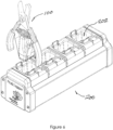
- the control module 108 is powered by means of a rechargeable battery (not shown) that is recharged in the charging base station 200 illustrated in Figure 6 .
- the charging base station 200 includes electrical charging contacts located within receptacles 202 formed in the charging base station 200 that are shaped complementally to the external shape of the control module housing 110.
- the charging base station 200 is configured to accept the control module housing 110 on its own or connected to pruning shears 102.
- the charging base station 200 may include a communications port and the charging base station 200 can be networked into a communications network including a central server computer.
- the charging base station 200, together with other similar base stations 200 may conveniently be located in a central location where the harvesters who operate the devices 100 will dock each harvesting device 100 with a base station on completion of the harvesting shift.
- the base station Once docked in such a communications-enabled charging base station 200, the base station, besides charging the battery of the harvesting device 100 also extracts the data logged by the harvesting device 100 from the device data store and transmits the extracted data to the server.
- the harvesting device subsystem 100 includes a satellite navigation system, preferably the Global Positioning System (GPS), to provide time and position data, the subsystem 100 being programmed to record, in respect of each separation stroke recorded, the GPS position of the harvesting device and the time the separation stroke was executed.
- GPS Global Positioning System
- a number of the subsystems of the produce harvesting system are communications-enabled by means of communications protocols, preferably one or more of Near Field Communications (NFC), Bluetooth TM (particularly Bluetooth Low Energy- BLE) and 1-Wire TM protocols, singly or in combination.
- communications protocols preferably one or more of Near Field Communications (NFC), Bluetooth TM (particularly Bluetooth Low Energy- BLE) and 1-Wire TM protocols, singly or in combination.
- the typical produce harvesting process involves the harvested produce (an orange for instance) being cut manually from the produce-bearing organism (an orange tree in the example) by shearing off the stem connecting the orange to the tree with a cutter, such as the pruning shears 102.
- the fruit is cut from the tree by a harvester (the person operating the shears 102) and deposited into a sling bag carried by the harvester.
- the harvester carries the sling bag to a produce transporting vehicle, normally a tractor-drawn trailer, where the produce is deposited by the harvester emptying the sling bag info a produce bin on the trailer.
- the produce bins on the trailer are filled to capacity, the produce bins are transported to a processing warehouse where the produce is deposited, weighed, sorted (according to size, qualify or the like) and finally packed.
- the data logging pruning shears 102 are used by a harvester to cut the produce, manually, from the produce-bearing organism.
- oranges are cut from an orange tree by shearing off the stem connecting the orange to the tree with the pruning shears 102.
- the separation stroke detector detects the stroke of the shears 102 separating the orange from the tree, by virtue of the magnet 122 actuating the reed switch in the control module 108.
- the reed switch signal is sent to the control module programmable logic means which is programmed to store the separation stroke in memory in the control module data store, together with the time and the GPS position of the pruning shears 102 at the time of the separation stroke. This data is referred to in this specification as "harvesting data”.
- the harvester deposits the cut fruit into a sling bag 126 carried by the harvester. Excluding the possibility of false positives, the stored number of separation strokes stored in memory in the data store should equate to the number of oranges harvested by the harvester.
- the harvester When the bag 126 is filled to capacity, the harvester carries the sling bag 126 to a trailer (not shown), where the produce is deposited by the harvester emptying the sling bag 126 into one of a number of produce bins 128 on the trailer.
- the produce bin 128 is communications-enabled and includes programmable logic means, including a data store.
- the control module 108 incorporates a communication device that is compatible with the bin communication device.
- the harvester Upon emptying the sling bag 126 into the produce bin 128, the harvester scans the control module 108 to the produce bin communication device or the control module 108 and the produce bin 128 communication device communicate automatically.
- control module RFID tag could tag into a bin RFID reader.
- control module programmable logic means is programmed to transfer (by moving or copying) the harvesting data stored in the control module data store to the produce bin data store.
- the warehouse 130 is provided with programmable logic means and is communications-enabled to communicate automatically with the communications devices in the produce bins 128.
- each bin 128 is placed on a scale (not shown) where the produce is weighed.
- the warehouse communication means is preferably associated with the scale or scales used to weigh the bins 128.
- the warehouse programmable logic means is programmed to transfer (by moving or copying) the harvesting data stored in the bin programmable logic means to the warehouse programmable logic means, which might include a communications network, a central server computer and a data store for the storage of harvesting data communicated from produce bins 128 by way of the warehouse scales.
- the central server computer could be the management system server.
- the produce bin 128, after weighing, is emptied into a sorting machine (not shown) which classifies the unpacked fruit into categories, typically based on one or more of size, quality, mass, colour, intended end-use or the like.
- the oranges of the example, for instance, are classified into categories including size, colour and quality, the latter determined by the intended end-use, for example export quality, domestic quality and juice quality.
- an unpacking report is prepared for the bin 128, in which this type of information is recorded in report format.
- the unpacking report data is uploaded to the management system server, which now has a digital data store including harvesting data and unpacking data, thereby incorporating data pertaining to almost every aspect of the harvesting process.
- the data is geographically mapped and includes the location of picking of the items of produce harvested, which data can be used to supplement the geographical data obtained by geographical surveys and stored in geographic information systems (GIS).
- GIS geographic information systems
- More granular reports than this are also possible. For instance, it is possible to produce an unpacking report for each bin 128 processed in the warehouse 130 and to map the unpacking data against GIS data to obtain per-bin quality maps, for instance.
- the picking data is analogous to the machine data associated with the so-called second wave of precision agriculture - data aggregated by the machines typically used in applying resources to and harvesting produce from previously surveyed fields and farmland.
Landscapes
- Life Sciences & Earth Sciences (AREA)
- Environmental Sciences (AREA)
- Engineering & Computer Science (AREA)
- Mechanical Engineering (AREA)
- Soil Sciences (AREA)
- Biodiversity & Conservation Biology (AREA)
- Ecology (AREA)
- Forests & Forestry (AREA)
- Management, Administration, Business Operations System, And Electronic Commerce (AREA)
- Harvesting Machines For Specific Crops (AREA)
- Harvester Elements (AREA)
- Combines (AREA)
Claims (8)
- Teilsystem (100) für Vorrichtungen zum Ernten von Erzeugnissen, umfassendeine manuelle individuelle Erntevorrichtung (102), die zur Befestigung an einer Person konfiguriert ist, die die Erntevorrichtung (102) festhält; undein Steuermodul (108), das programmierbare Logikmittel und einen Trennungshubdetektor enthält, der dazu konfiguriert ist, im Einsatz die Erntevorrichtung (102) zu überwachen und eine Aktion der Erntevorrichtung (102) zu detektieren, die mit einem vorbestimmten Erzeugnistrennungshub übereinstimmt, mit dessen Hilfe die Erntevorrichtung (102) die geernteten Erzeugnisse von einem erzeugnisbildenden Organismus im Einsatz trennt, wobei die programmierbaren Logikmittel dazu programmiert sind, jeden detektierten Erzeugnistrennungshub in einem Trennungshubzähler aufzuzeichnen;wobei die Erntevorrichtung (102) eine manuell betätigbare, schwenkbare Erntevorrichtung vom Scherentyp ist, das Steuermodul (108) von der Erntevorrichtung (102) separat ist und abnehmbar an dieser montiert ist und der Trennungshubdetektor dazu konfiguriert ist, eine Aktion der Erntevorrichtung (102) zu überwachen, indem es überwacht, wann Griffe (104) der Erntevorrichtung (102) manuell zusammengedrückt werden, um eine schwenkbare Scheraktion durchzuführen.
- Teilsystem (100) für Vorrichtungen zum Ernten von Erzeugnissen nach Anspruch 1, dadurch gekennzeichnet, dass die programmierbaren Logikmittel dazu konfiguriert sind, über einen vorbestimmten Zeitraum vom Trennungshubdetektor detektierte Erzeugnistrennungshübe autonom aufzuzeichnen, wobei die programmierbaren Logikmittel einen digitalen Datenspeicher enthalten, der dazu konfiguriert ist, die im Datenspeicher gespeicherten Daten zu empfangen, zu speichern und deren Abruf zu ermöglichen.
- Teilsystem (100) für Vorrichtungen zum Ernten von Erzeugnissen nach Anspruch 2, bei dem das Steuermodul (108) Tageszeit- und Geostandortmittel enthält, wobei die programmierbaren Logikmittel dazu konfiguriert sind, Erntedaten in Bezug auf mindestens einen Teil der vom Trennungshubdetektor detektierten Trennungshübe aufzuzeichnen, wobei die Erntedaten Daten im Zusammenhang mit den detektierten Trennungshüben, der Tageszeit, zu der die Trennungshübe vorgenommen werden, und dem Geostandort, an dem die Hübe vorgenommen wurden, enthalten.
- System zum Ernten von Erzeugnissen, wobei das System das Teilsystem (100) zum Ernten von Erzeugnissen nach Anspruch 3 umfasst und ferner ein Verwaltungsteilsystem für die Ernte von Erzeugnissen enthält, das dazu konfiguriert ist, mit einer Vielzahl von Teilsystemen (100) für Vorrichtungen zum Ernten von Erzeugnissen in Verbindung zu stehen, wobei das Verwaltungsteilsystem programmierbare Logikmittel enthält, die dazu programmiert sind, die Erntedaten von einer Vielzahl von Teilsystemen (100) für Erntevorrichtungen abzurufen und die Erntedaten zu speichern und zu verwalten.
- Teilsystem (100) für Vorrichtungen zum Ernten von Erzeugnissen nach einem der vorhergehenden Ansprüche 1-3, dadurch gekennzeichnet, dass das Steuermodul (108) Datenspeichermittel, Standortbestimmungsmittel, Kommunikationsmittel und eine Stromversorgung enthält.
- Teilsystem (100) für Vorrichtungen zum Ernten von Erzeugnissen nach einem der vorhergehenden Ansprüche 1-3 oder 5,
dadurch gekennzeichnet, dass der Hubdetektor einen magnetischen Reed-Schalter umfasst, der so positioniert ist, dass er in Abhängigkeit von der Nähe eines Magneten zu schalten, der zur Bewegung in die und aus der Nähe des Reed-Schalters bei jedem Trennungshub der Erntevorrichtung (102) montiert ist. - Teilsystem (100) für Vorrichtungen zum Ernten von Erzeugnissen nach einem der Ansprüche 1-3 oder 5,
dadurch gekennzeichnet, dass der Hubdetektor aus einer Fotodiode besteht, die ein lichtemittierendes Element und ein gegenüberliegendes, ausgerichtetes Fotodetektorelement enthält, die einander über einen Abstandsspalt zugewandt sind, der einen optischen Freiraumpfad definiert, wobei der Fotounterbrecher an der Erntevorrichtung (102) derart montiert ist, dass der optische Pfad bei jedem Trennungshub beeinflusst wird. - Teilsystem (100) für Vorrichtungen zum Ernten von Erzeugnissen nach einem der vorhergehenden Ansprüche 1-3 oder 5-7,
dadurch gekennzeichnet, dass der Trennungshubdetektor einen Beschleunigungsmesser umfasst, der an der Erntevorrichtung (102) montiert ist, wobei der Beschleunigungsmesser dazu konfiguriert ist, eine Beschleunigungssignatur zu detektieren, die als typisch für einen Trennungshub der Erntevorrichtung (102) vorbestimmt wurde.
Applications Claiming Priority (2)
| Application Number | Priority Date | Filing Date | Title |
|---|---|---|---|
| ZA201801375 | 2018-02-28 | ||
| PCT/ZA2019/050008 WO2019169413A2 (en) | 2018-02-28 | 2019-02-28 | Produce harvesting apparatus and precision farming system |
Publications (4)
| Publication Number | Publication Date |
|---|---|
| EP3758467A2 EP3758467A2 (de) | 2021-01-06 |
| EP3758467A4 EP3758467A4 (de) | 2021-11-24 |
| EP3758467B1 true EP3758467B1 (de) | 2024-12-11 |
| EP3758467C0 EP3758467C0 (de) | 2024-12-11 |
Family
ID=67805560
Family Applications (1)
| Application Number | Title | Priority Date | Filing Date |
|---|---|---|---|
| EP19760424.2A Active EP3758467B1 (de) | 2018-02-28 | 2019-02-28 | Vorrichtung zum ernten von landwirtschaftlichen erzeugnissen und präzisionslandwirtschaftssystem |
Country Status (13)
| Country | Link |
|---|---|
| US (1) | US11944031B2 (de) |
| EP (1) | EP3758467B1 (de) |
| AU (1) | AU2019226618B2 (de) |
| CL (1) | CL2020002208A1 (de) |
| CO (1) | CO2020011934A2 (de) |
| DO (1) | DOP2020000163A (de) |
| ES (1) | ES3009902T3 (de) |
| IL (1) | IL276986B2 (de) |
| MA (1) | MA51354B1 (de) |
| MX (1) | MX2020008975A (de) |
| PE (1) | PE20210087A1 (de) |
| WO (1) | WO2019169413A2 (de) |
| ZA (1) | ZA202005963B (de) |
Families Citing this family (6)
| Publication number | Priority date | Publication date | Assignee | Title |
|---|---|---|---|---|
| EP3758467B1 (de) | 2018-02-28 | 2024-12-11 | Agri Technovation (Pty) Ltd | Vorrichtung zum ernten von landwirtschaftlichen erzeugnissen und präzisionslandwirtschaftssystem |
| CN113475213B (zh) * | 2021-07-27 | 2022-05-10 | 济宁市农业科学研究院 | 马铃薯雄蕊采集器及其使用方法 |
| WO2023113588A1 (en) * | 2021-12-17 | 2023-06-22 | Irga Sdn. Bhd. | An improved cutter |
| CN115349364B (zh) * | 2022-08-15 | 2023-08-22 | 中山庆琏金属制品有限公司 | 一种智能助力园林剪刀及判断植物健康状态控制方法 |
| USD1027586S1 (en) * | 2023-03-24 | 2024-05-21 | Ramón Manzana S.L. | Clippers |
| WO2025088592A2 (en) * | 2023-10-26 | 2025-05-01 | Inesc Tec - Instituto De Engenharia De Sistemas E Computadores, Tecnologia E Ciência | Add-on monitoring apparatus for a cutting tool, respective cutting tool, monitoring system and method |
Family Cites Families (12)
| Publication number | Priority date | Publication date | Assignee | Title |
|---|---|---|---|---|
| DE8814543U1 (de) | 1988-11-22 | 1989-01-19 | NIKO Nippert Maschinenbau, 7580 Bühl | Maschinelle Handschere, insbesondere für die Landwirtschaft |
| JP2004133498A (ja) * | 2002-10-08 | 2004-04-30 | Sakae Shibusawa | 精密農法情報管理システム |
| ES2268954B1 (es) | 2005-01-27 | 2008-03-01 | Josep Gurri Molins | Util de corte motorizado portatil. |
| BRPI0924132A2 (pt) * | 2009-01-23 | 2016-02-10 | Qualcomm Mems Technologies Inc | dispositivo e sistema de iluminação e métodos de fabricação de dispositivo de iluminação e de detecção do movimento de objeto através de painel de iluminação |
| FR2957834B1 (fr) * | 2010-03-24 | 2012-03-09 | Infaco | Dispositif de controle positionnel de deux elements l'un par rapport a l'autre tel que lames d'outils de coupe du genre secateur et outil de coupe le comportant |
| US10151839B2 (en) * | 2012-06-01 | 2018-12-11 | Agerpoint, Inc. | Systems and methods for determining crop yields with high resolution geo-referenced sensors |
| US10055700B2 (en) * | 2014-03-30 | 2018-08-21 | Trimble Inc. | Intelligent tool for collecting and managing data during manual harvesting of fruits and vegetables |
| US10109024B2 (en) * | 2014-09-05 | 2018-10-23 | The Climate Corporation | Collecting data to generate an agricultural prescription |
| US10548256B2 (en) * | 2015-08-28 | 2020-02-04 | Graham Equipment, LLC | Precision agricultural-device control system and wireless agricultural-device communication protocol |
| EP3430885B1 (de) | 2015-09-14 | 2019-12-04 | Max Co., Ltd. | Fremdstoffdetektionsmechanismus für eine elektrische schere |
| FR3063866B1 (fr) | 2017-03-16 | 2021-05-21 | Soufflet Vigne | Ensemble et procede pour la culture de plantes perennes telles que des vignes, mettant en oeuvre la gestion de donnees collectees lors de l'utilisation d'un outil de coupe portatif |
| EP3758467B1 (de) | 2018-02-28 | 2024-12-11 | Agri Technovation (Pty) Ltd | Vorrichtung zum ernten von landwirtschaftlichen erzeugnissen und präzisionslandwirtschaftssystem |
-
2019
- 2019-02-28 EP EP19760424.2A patent/EP3758467B1/de active Active
- 2019-02-28 IL IL276986A patent/IL276986B2/en unknown
- 2019-02-28 US US16/976,488 patent/US11944031B2/en active Active
- 2019-02-28 ES ES19760424T patent/ES3009902T3/es active Active
- 2019-02-28 PE PE2020001300A patent/PE20210087A1/es unknown
- 2019-02-28 WO PCT/ZA2019/050008 patent/WO2019169413A2/en not_active Ceased
- 2019-02-28 MX MX2020008975A patent/MX2020008975A/es unknown
- 2019-02-28 MA MA51354A patent/MA51354B1/fr unknown
- 2019-02-28 AU AU2019226618A patent/AU2019226618B2/en active Active
-
2020
- 2020-08-27 DO DO2020000163A patent/DOP2020000163A/es unknown
- 2020-08-27 CL CL2020002208A patent/CL2020002208A1/es unknown
- 2020-09-28 CO CONC2020/0011934A patent/CO2020011934A2/es unknown
- 2020-09-28 ZA ZA2020/05963A patent/ZA202005963B/en unknown
Also Published As
| Publication number | Publication date |
|---|---|
| IL276986B2 (en) | 2025-07-01 |
| US11944031B2 (en) | 2024-04-02 |
| IL276986B1 (en) | 2025-03-01 |
| ZA202005963B (en) | 2021-08-25 |
| CL2020002208A1 (es) | 2021-02-12 |
| MA51354A1 (fr) | 2021-09-30 |
| AU2019226618B2 (en) | 2025-02-13 |
| EP3758467A4 (de) | 2021-11-24 |
| WO2019169413A3 (en) | 2020-03-19 |
| ES3009902T3 (en) | 2025-03-31 |
| IL276986A (en) | 2020-10-29 |
| EP3758467C0 (de) | 2024-12-11 |
| DOP2020000163A (es) | 2021-03-15 |
| MX2020008975A (es) | 2020-12-10 |
| AU2019226618A1 (en) | 2020-10-15 |
| CO2020011934A2 (es) | 2020-10-30 |
| EP3758467A2 (de) | 2021-01-06 |
| WO2019169413A2 (en) | 2019-09-06 |
| PE20210087A1 (es) | 2021-01-11 |
| US20210360848A1 (en) | 2021-11-25 |
| MA51354B1 (fr) | 2024-07-31 |
| BR112020017616A2 (pt) | 2020-12-22 |
Similar Documents
| Publication | Publication Date | Title |
|---|---|---|
| EP3758467B1 (de) | Vorrichtung zum ernten von landwirtschaftlichen erzeugnissen und präzisionslandwirtschaftssystem | |
| Longchamps et al. | Yield sensing technologies for perennial and annual horticultural crops: a review | |
| Suprem et al. | A review on application of technology systems, standards and interfaces for agriculture and food sector | |
| US5845229A (en) | Method and apparatus for mapping crop quality | |
| ES2762607T3 (es) | Método y disposición para monitorizar la recogida de material vegetal | |
| US7765780B2 (en) | Agricultural robot system and method | |
| EP1984815A2 (de) | Verfahren zur verfolgung handgeernteter obstfrüchte | |
| US9836036B2 (en) | Agricultural implement with automated recognition of seed attributes | |
| CN112911931A (zh) | 节肢动物的检测 | |
| Ampatzidis et al. | Training system affects sweet cherry harvest efficiency | |
| EP3893625B1 (de) | Multifunktionales system für anpassbares ernten | |
| EP1984886A2 (de) | Verfahren zur verfolgung handgeernteter feldpflanzen | |
| CN103196486A (zh) | 基于无线传感网络的烟草仓储监测系统及方法 | |
| US12484569B2 (en) | Method and system for monitoring and controlling the presence of at least one type of insect in agricultural crops | |
| CN208207247U (zh) | 一种农业气象灾害预警系统 | |
| WO2014031434A1 (en) | Rfid-based plant tracking and data management system for a greenhouse | |
| Ampatzidis et al. | Development and evaluation of a novel system for monitoring harvest labor efficiency | |
| Ampatzidis et al. | Portable weighing system for monitoring picker efficiency during manual harvest of sweet cherry | |
| BR112020017616B1 (pt) | Subsistema de dispositivo de colheita de produtos hortifrutícolas | |
| CN109146508A (zh) | 一种基于无人机的农产品溯源系统 | |
| JP2022047500A (ja) | 情報管理システム | |
| WO2024105405A1 (en) | Fruit picking trolley | |
| CN119255698A (zh) | 用于控制植物繁殖结构疏化的系统和方法 | |
| Kumar et al. | Robots for Harvesting of Horticultural Crop: A Review | |
| EP4640043A1 (de) | Vorrichtung und verfahren zur messung des wachstums eines lebewesens mit einem drahtlosen kommunikationsetikett und einem längenmesswerkzeug |
Legal Events
| Date | Code | Title | Description |
|---|---|---|---|
| STAA | Information on the status of an ep patent application or granted ep patent |
Free format text: STATUS: THE INTERNATIONAL PUBLICATION HAS BEEN MADE |
|
| PUAI | Public reference made under article 153(3) epc to a published international application that has entered the european phase |
Free format text: ORIGINAL CODE: 0009012 |
|
| STAA | Information on the status of an ep patent application or granted ep patent |
Free format text: STATUS: REQUEST FOR EXAMINATION WAS MADE |
|
| 17P | Request for examination filed |
Effective date: 20200925 |
|
| AK | Designated contracting states |
Kind code of ref document: A2 Designated state(s): AL AT BE BG CH CY CZ DE DK EE ES FI FR GB GR HR HU IE IS IT LI LT LU LV MC MK MT NL NO PL PT RO RS SE SI SK SM TR |
|
| AX | Request for extension of the european patent |
Extension state: BA ME |
|
| DAV | Request for validation of the european patent (deleted) | ||
| DAX | Request for extension of the european patent (deleted) | ||
| A4 | Supplementary search report drawn up and despatched |
Effective date: 20211021 |
|
| RIC1 | Information provided on ipc code assigned before grant |
Ipc: A01B 79/00 20060101ALN20211015BHEP Ipc: A01G 3/02 20060101ALI20211015BHEP Ipc: A01D 1/00 20060101AFI20211015BHEP |
|
| GRAP | Despatch of communication of intention to grant a patent |
Free format text: ORIGINAL CODE: EPIDOSNIGR1 |
|
| STAA | Information on the status of an ep patent application or granted ep patent |
Free format text: STATUS: GRANT OF PATENT IS INTENDED |
|
| RIC1 | Information provided on ipc code assigned before grant |
Ipc: A01B 79/00 20060101ALN20240702BHEP Ipc: A01G 3/02 20060101ALI20240702BHEP Ipc: A01D 1/00 20060101AFI20240702BHEP |
|
| INTG | Intention to grant announced |
Effective date: 20240715 |
|
| GRAS | Grant fee paid |
Free format text: ORIGINAL CODE: EPIDOSNIGR3 |
|
| GRAA | (expected) grant |
Free format text: ORIGINAL CODE: 0009210 |
|
| STAA | Information on the status of an ep patent application or granted ep patent |
Free format text: STATUS: THE PATENT HAS BEEN GRANTED |
|
| AK | Designated contracting states |
Kind code of ref document: B1 Designated state(s): AL AT BE BG CH CY CZ DE DK EE ES FI FR GB GR HR HU IE IS IT LI LT LU LV MC MK MT NL NO PL PT RO RS SE SI SK SM TR |
|
| REG | Reference to a national code |
Ref country code: GB Ref legal event code: FG4D |
|
| REG | Reference to a national code |
Ref country code: CH Ref legal event code: EP |
|
| REG | Reference to a national code |
Ref country code: IE Ref legal event code: FG4D |
|
| REG | Reference to a national code |
Ref country code: DE Ref legal event code: R096 Ref document number: 602019063393 Country of ref document: DE |
|
| U01 | Request for unitary effect filed |
Effective date: 20250103 |
|
| U07 | Unitary effect registered |
Designated state(s): AT BE BG DE DK EE FI FR IT LT LU LV MT NL PT RO SE SI Effective date: 20250115 |
|
| U20 | Renewal fee for the european patent with unitary effect paid |
Year of fee payment: 7 Effective date: 20250131 |
|
| REG | Reference to a national code |
Ref country code: ES Ref legal event code: FG2A Ref document number: 3009902 Country of ref document: ES Kind code of ref document: T3 Effective date: 20250331 |
|
| PG25 | Lapsed in a contracting state [announced via postgrant information from national office to epo] |
Ref country code: HR Free format text: LAPSE BECAUSE OF FAILURE TO SUBMIT A TRANSLATION OF THE DESCRIPTION OR TO PAY THE FEE WITHIN THE PRESCRIBED TIME-LIMIT Effective date: 20241211 |
|
| PGFP | Annual fee paid to national office [announced via postgrant information from national office to epo] |
Ref country code: ES Payment date: 20250301 Year of fee payment: 7 |
|
| PG25 | Lapsed in a contracting state [announced via postgrant information from national office to epo] |
Ref country code: NO Free format text: LAPSE BECAUSE OF FAILURE TO SUBMIT A TRANSLATION OF THE DESCRIPTION OR TO PAY THE FEE WITHIN THE PRESCRIBED TIME-LIMIT Effective date: 20250311 |
|
| PG25 | Lapsed in a contracting state [announced via postgrant information from national office to epo] |
Ref country code: GR Free format text: LAPSE BECAUSE OF FAILURE TO SUBMIT A TRANSLATION OF THE DESCRIPTION OR TO PAY THE FEE WITHIN THE PRESCRIBED TIME-LIMIT Effective date: 20250312 |
|
| PG25 | Lapsed in a contracting state [announced via postgrant information from national office to epo] |
Ref country code: RS Free format text: LAPSE BECAUSE OF FAILURE TO SUBMIT A TRANSLATION OF THE DESCRIPTION OR TO PAY THE FEE WITHIN THE PRESCRIBED TIME-LIMIT Effective date: 20250311 |
|
| PGFP | Annual fee paid to national office [announced via postgrant information from national office to epo] |
Ref country code: TR Payment date: 20250120 Year of fee payment: 7 |
|
| PG25 | Lapsed in a contracting state [announced via postgrant information from national office to epo] |
Ref country code: SM Free format text: LAPSE BECAUSE OF FAILURE TO SUBMIT A TRANSLATION OF THE DESCRIPTION OR TO PAY THE FEE WITHIN THE PRESCRIBED TIME-LIMIT Effective date: 20241211 |
|
| PG25 | Lapsed in a contracting state [announced via postgrant information from national office to epo] |
Ref country code: PL Free format text: LAPSE BECAUSE OF FAILURE TO SUBMIT A TRANSLATION OF THE DESCRIPTION OR TO PAY THE FEE WITHIN THE PRESCRIBED TIME-LIMIT Effective date: 20241211 |
|
| PG25 | Lapsed in a contracting state [announced via postgrant information from national office to epo] |
Ref country code: IS Free format text: LAPSE BECAUSE OF FAILURE TO SUBMIT A TRANSLATION OF THE DESCRIPTION OR TO PAY THE FEE WITHIN THE PRESCRIBED TIME-LIMIT Effective date: 20250411 |
|
| PG25 | Lapsed in a contracting state [announced via postgrant information from national office to epo] |
Ref country code: SK Free format text: LAPSE BECAUSE OF FAILURE TO SUBMIT A TRANSLATION OF THE DESCRIPTION OR TO PAY THE FEE WITHIN THE PRESCRIBED TIME-LIMIT Effective date: 20241211 |
|
| PG25 | Lapsed in a contracting state [announced via postgrant information from national office to epo] |
Ref country code: CZ Free format text: LAPSE BECAUSE OF FAILURE TO SUBMIT A TRANSLATION OF THE DESCRIPTION OR TO PAY THE FEE WITHIN THE PRESCRIBED TIME-LIMIT Effective date: 20241211 |
|
| PG25 | Lapsed in a contracting state [announced via postgrant information from national office to epo] |
Ref country code: MC Free format text: LAPSE BECAUSE OF FAILURE TO SUBMIT A TRANSLATION OF THE DESCRIPTION OR TO PAY THE FEE WITHIN THE PRESCRIBED TIME-LIMIT Effective date: 20241211 |
|
| REG | Reference to a national code |
Ref country code: CH Ref legal event code: PL |
|
| PLBE | No opposition filed within time limit |
Free format text: ORIGINAL CODE: 0009261 |
|
| STAA | Information on the status of an ep patent application or granted ep patent |
Free format text: STATUS: NO OPPOSITION FILED WITHIN TIME LIMIT |
|
| PG25 | Lapsed in a contracting state [announced via postgrant information from national office to epo] |
Ref country code: CH Free format text: LAPSE BECAUSE OF NON-PAYMENT OF DUE FEES Effective date: 20250228 |
|
| 26N | No opposition filed |
Effective date: 20250912 |
|
| GBPC | Gb: european patent ceased through non-payment of renewal fee |
Effective date: 20250311 |
|
| PG25 | Lapsed in a contracting state [announced via postgrant information from national office to epo] |
Ref country code: GB Free format text: LAPSE BECAUSE OF NON-PAYMENT OF DUE FEES Effective date: 20250311 |
|
| PG25 | Lapsed in a contracting state [announced via postgrant information from national office to epo] |
Ref country code: IE Free format text: LAPSE BECAUSE OF NON-PAYMENT OF DUE FEES Effective date: 20250228 |