EP3757985A1 - Electronic musical instrument, method and program - Google Patents
Electronic musical instrument, method and program Download PDFInfo
- Publication number
- EP3757985A1 EP3757985A1 EP20180039.8A EP20180039A EP3757985A1 EP 3757985 A1 EP3757985 A1 EP 3757985A1 EP 20180039 A EP20180039 A EP 20180039A EP 3757985 A1 EP3757985 A1 EP 3757985A1
- Authority
- EP
- European Patent Office
- Prior art keywords
- waveforms
- data
- waveform
- waveform data
- envelope
- Prior art date
- Legal status (The legal status is an assumption and is not a legal conclusion. Google has not performed a legal analysis and makes no representation as to the accuracy of the status listed.)
- Granted
Links
Images






Classifications
-
- G—PHYSICS
- G10—MUSICAL INSTRUMENTS; ACOUSTICS
- G10H—ELECTROPHONIC MUSICAL INSTRUMENTS; INSTRUMENTS IN WHICH THE TONES ARE GENERATED BY ELECTROMECHANICAL MEANS OR ELECTRONIC GENERATORS, OR IN WHICH THE TONES ARE SYNTHESISED FROM A DATA STORE
- G10H1/00—Details of electrophonic musical instruments
- G10H1/02—Means for controlling the tone frequencies, e.g. attack or decay; Means for producing special musical effects, e.g. vibratos or glissandos
- G10H1/04—Means for controlling the tone frequencies, e.g. attack or decay; Means for producing special musical effects, e.g. vibratos or glissandos by additional modulation
- G10H1/053—Means for controlling the tone frequencies, e.g. attack or decay; Means for producing special musical effects, e.g. vibratos or glissandos by additional modulation during execution only
-
- G—PHYSICS
- G10—MUSICAL INSTRUMENTS; ACOUSTICS
- G10H—ELECTROPHONIC MUSICAL INSTRUMENTS; INSTRUMENTS IN WHICH THE TONES ARE GENERATED BY ELECTROMECHANICAL MEANS OR ELECTRONIC GENERATORS, OR IN WHICH THE TONES ARE SYNTHESISED FROM A DATA STORE
- G10H1/00—Details of electrophonic musical instruments
-
- G—PHYSICS
- G10—MUSICAL INSTRUMENTS; ACOUSTICS
- G10H—ELECTROPHONIC MUSICAL INSTRUMENTS; INSTRUMENTS IN WHICH THE TONES ARE GENERATED BY ELECTROMECHANICAL MEANS OR ELECTRONIC GENERATORS, OR IN WHICH THE TONES ARE SYNTHESISED FROM A DATA STORE
- G10H1/00—Details of electrophonic musical instruments
- G10H1/02—Means for controlling the tone frequencies, e.g. attack or decay; Means for producing special musical effects, e.g. vibratos or glissandos
-
- G—PHYSICS
- G10—MUSICAL INSTRUMENTS; ACOUSTICS
- G10H—ELECTROPHONIC MUSICAL INSTRUMENTS; INSTRUMENTS IN WHICH THE TONES ARE GENERATED BY ELECTROMECHANICAL MEANS OR ELECTRONIC GENERATORS, OR IN WHICH THE TONES ARE SYNTHESISED FROM A DATA STORE
- G10H1/00—Details of electrophonic musical instruments
- G10H1/02—Means for controlling the tone frequencies, e.g. attack or decay; Means for producing special musical effects, e.g. vibratos or glissandos
- G10H1/06—Circuits for establishing the harmonic content of tones, or other arrangements for changing the tone colour
-
- G—PHYSICS
- G10—MUSICAL INSTRUMENTS; ACOUSTICS
- G10H—ELECTROPHONIC MUSICAL INSTRUMENTS; INSTRUMENTS IN WHICH THE TONES ARE GENERATED BY ELECTROMECHANICAL MEANS OR ELECTRONIC GENERATORS, OR IN WHICH THE TONES ARE SYNTHESISED FROM A DATA STORE
- G10H1/00—Details of electrophonic musical instruments
- G10H1/02—Means for controlling the tone frequencies, e.g. attack or decay; Means for producing special musical effects, e.g. vibratos or glissandos
- G10H1/06—Circuits for establishing the harmonic content of tones, or other arrangements for changing the tone colour
- G10H1/14—Circuits for establishing the harmonic content of tones, or other arrangements for changing the tone colour during execution
-
- G—PHYSICS
- G10—MUSICAL INSTRUMENTS; ACOUSTICS
- G10H—ELECTROPHONIC MUSICAL INSTRUMENTS; INSTRUMENTS IN WHICH THE TONES ARE GENERATED BY ELECTROMECHANICAL MEANS OR ELECTRONIC GENERATORS, OR IN WHICH THE TONES ARE SYNTHESISED FROM A DATA STORE
- G10H1/00—Details of electrophonic musical instruments
- G10H1/02—Means for controlling the tone frequencies, e.g. attack or decay; Means for producing special musical effects, e.g. vibratos or glissandos
- G10H1/06—Circuits for establishing the harmonic content of tones, or other arrangements for changing the tone colour
- G10H1/16—Circuits for establishing the harmonic content of tones, or other arrangements for changing the tone colour by non-linear elements
-
- G—PHYSICS
- G10—MUSICAL INSTRUMENTS; ACOUSTICS
- G10H—ELECTROPHONIC MUSICAL INSTRUMENTS; INSTRUMENTS IN WHICH THE TONES ARE GENERATED BY ELECTROMECHANICAL MEANS OR ELECTRONIC GENERATORS, OR IN WHICH THE TONES ARE SYNTHESISED FROM A DATA STORE
- G10H7/00—Instruments in which the tones are synthesised from a data store, e.g. computer organs
- G10H7/02—Instruments in which the tones are synthesised from a data store, e.g. computer organs in which amplitudes at successive sample points of a tone waveform are stored in one or more memories
-
- G—PHYSICS
- G10—MUSICAL INSTRUMENTS; ACOUSTICS
- G10H—ELECTROPHONIC MUSICAL INSTRUMENTS; INSTRUMENTS IN WHICH THE TONES ARE GENERATED BY ELECTROMECHANICAL MEANS OR ELECTRONIC GENERATORS, OR IN WHICH THE TONES ARE SYNTHESISED FROM A DATA STORE
- G10H1/00—Details of electrophonic musical instruments
- G10H1/02—Means for controlling the tone frequencies, e.g. attack or decay; Means for producing special musical effects, e.g. vibratos or glissandos
- G10H1/04—Means for controlling the tone frequencies, e.g. attack or decay; Means for producing special musical effects, e.g. vibratos or glissandos by additional modulation
- G10H1/053—Means for controlling the tone frequencies, e.g. attack or decay; Means for producing special musical effects, e.g. vibratos or glissandos by additional modulation during execution only
- G10H1/057—Means for controlling the tone frequencies, e.g. attack or decay; Means for producing special musical effects, e.g. vibratos or glissandos by additional modulation during execution only by envelope-forming circuits
-
- G—PHYSICS
- G10—MUSICAL INSTRUMENTS; ACOUSTICS
- G10H—ELECTROPHONIC MUSICAL INSTRUMENTS; INSTRUMENTS IN WHICH THE TONES ARE GENERATED BY ELECTROMECHANICAL MEANS OR ELECTRONIC GENERATORS, OR IN WHICH THE TONES ARE SYNTHESISED FROM A DATA STORE
- G10H1/00—Details of electrophonic musical instruments
- G10H1/18—Selecting circuits
-
- G—PHYSICS
- G10—MUSICAL INSTRUMENTS; ACOUSTICS
- G10H—ELECTROPHONIC MUSICAL INSTRUMENTS; INSTRUMENTS IN WHICH THE TONES ARE GENERATED BY ELECTROMECHANICAL MEANS OR ELECTRONIC GENERATORS, OR IN WHICH THE TONES ARE SYNTHESISED FROM A DATA STORE
- G10H2210/00—Aspects or methods of musical processing having intrinsic musical character, i.e. involving musical theory or musical parameters or relying on musical knowledge, as applied in electrophonic musical tools or instruments
- G10H2210/155—Musical effects
- G10H2210/265—Acoustic effect simulation, i.e. volume, spatial, resonance or reverberation effects added to a musical sound, usually by appropriate filtering or delays
-
- G—PHYSICS
- G10—MUSICAL INSTRUMENTS; ACOUSTICS
- G10H—ELECTROPHONIC MUSICAL INSTRUMENTS; INSTRUMENTS IN WHICH THE TONES ARE GENERATED BY ELECTROMECHANICAL MEANS OR ELECTRONIC GENERATORS, OR IN WHICH THE TONES ARE SYNTHESISED FROM A DATA STORE
- G10H2250/00—Aspects of algorithms or signal processing methods without intrinsic musical character, yet specifically adapted for or used in electrophonic musical processing
- G10H2250/541—Details of musical waveform synthesis, i.e. audio waveshape processing from individual wavetable samples, independently of their origin or of the sound they represent
Definitions
- the present disclosure relates to an electronic musical instrument, a method and a program.
- JP-A-2011-154394 discloses technology of reproducing a sound of a damper coming into contact with a vibrating string upon key release of an acoustic piano.
- An electronic musical instrument related to one aspect of the present disclosure includes: means for determining, in accordance with a user operation on at least one operation element, first waveform data from a plurality of pieces of waveform data, the first waveform data including multiple first waveforms having different first amplitudes; means for generating normalized data that includes multiple second waveforms having same second amplitude, based on the first waveform data; means for amplifying the second amplitude of at least one of the multiple second waveforms in the normalized data to generate amplified data; means for clipping at least one waveform included in the amplified data at a certain clipping level to generate clipped data that includes multiple third waveforms; and means for changing amplitudes of the multiple third waveforms in the clipped data to the different first amplitudes to generate waveform data that includes multiple fourth waveforms.
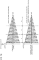
- FIG. 1A is a view for illustrating a contact sound that is generated in an acoustic piano.
- FIG. 1B illustrates an output image diagram of a waveform that does not include a contact sound generated in the acoustic piano (Comparative Example), and an output image diagram of a waveform that includes the contact sound (first embodiment).
- a level of sound i.e., an amplitude of a waveform upon the key release is controlled so as to change over time, in accordance with an envelope that reproduces an envelope of amplitudes of the string 130 upon the key release.
- the change in contact sound over time as described above is not reproduced. Therefore, in an electronic musical instrument of the present embodiment, as shown in a lower drawing of FIG.
- amplitudes of a waveform are restricted when the amplitudes exceed certain levels (levels of a broken line) indicating threshold values of generation of the contact sound, and a distortion sound corresponding to a waveform of which amplitudes are restricted is thus generated as a sound that simulates the contact sound.
- levels levels of a broken line
- a distortion sound corresponding to a waveform of which amplitudes are restricted is thus generated as a sound that simulates the contact sound.
- amplitudes of a waveform corresponding to a sound upon the key release of the acoustic piano 100 are controlled so as to be largely restricted over time.
- the distortion sound as the contact sound is controlled so as to be further emphasized as a time period k1, a time period k2, and a time period k3 progress, as shown in the lower drawing of FIG.
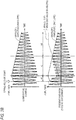
- FIG. 2A is a view for illustrating a contact sound that is generated in a guitar.
- FIG. 2B is an output image diagram of a waveform that does not include a contact sound generated in the guitar (Comparative Example), and an output image diagram of a waveform that includes the contact sound (second embodiment).
- a contact sound is generated. More specifically, while the finger F presses the string 210, the contact sound is not generated because the string 210 vibrates about a fret 220 as a support point. However, when the finger F starts to move away from the fret 220, the support point of the string 210 moves from the fret 220 to the finger F, so that the string 210 vibrates about the finger F as a support point. When the string 210 comes into contact with the fret 220 or the like, the contact sound is generated.
- the contact sound starts to be heard immediately after the string releases, unlike the acoustic piano 100. Then, as the amplitude of the string 210 becomes smaller over time or the finger F moves away from the fret 220, the contact sound becomes difficult to be heard.
- a level of sound i.e., an amplitude of a waveform upon the key release is controlled so as to change over time, in accordance with an envelope that reproduces an envelope of amplitudes of the string 210 upon the key release. More specifically, the amplitude of the waveform is controlled so as to increase over time during a time period k4 immediately after the key release of the electronic musical instrument, i.e., immediately after the string release of the guitar 200, and to attenuate over time during time periods k5 and k6 thereafter, for example. Also, a clipping level is set as shown in a lower drawing of FIG. 2B , for example.
- the distortion sound as the contact sound is controlled so that it is emphasized over time during the time period k4 (because the difference value between the threshold value of the broken line and the solid line value of the solid line becomes gradually larger), is attenuated over time during the time period k5 (because the difference value between the threshold value of the broken line and the solid line value of the solid line becomes gradually smaller), and is not heard during the time period k6 (because the solid line value has not reached the threshold value).
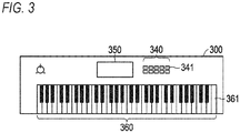
- FIG. 3 depicts an example of an outer shape of an electronic musical instrument in accordance with an embodiment of the present disclosure.
- FIG. 4 is a block diagram depicting a hardware configuration of the electronic musical instrument.
- an electronic musical instrument 300 includes a CPU (Central Processing Unit) 310, a RAM (Random Access Memory) 320, a ROM (Read Only Memory) 330, a switch panel 340, an LCD (liquid crystal monitor) 350, a keyboard 360, a sound source LSI (large-scale integration) 370, a D/A converter 380, an amplifier 385 and a timer counter 390.
- the CPU 310, the RAM 320, the ROM 330 and the sound source LSI 370 are each connected to a bus 395.
- the switch panel 340, the LCD 350 and the keyboard 360 are each connected to the bus 395 via each of an I/O interface 345, an LCD controller 355 and a key scanner 365.
- the CPU 310 as a processor is configured to control the respective constituent elements and to execute a variety of calculation processing, in accordance with programs.
- the RAM 320 is configured to temporarily store programs, data and the like, as a work area.
- the ROM 330 as a memory has a program area and a data area, and stores a variety of programs, data and the like in advance.
- the ROM 330 is configured to store a plurality of pieces of waveform data corresponding to multiple musical instrument sounds, as a waveform memory, for example.
- the switch panel 340 includes a plurality of switches 341, and is configured to receive a user operation of pressing each of the plurality of switches 341.
- the switch panel 340 includes the plurality of switches 341 corresponding to multiple musical instrument sounds, and receives a user operation of selecting a certain musical instrument sound from the multiple musical instrument sounds.
- the I/O interface 345 is configured to monitor each of the plurality of switches 341 of the switch panel 340, and, when it is detected that each of the plurality of switches 341 is pressed, notifies the detection to the CPU 310.
- the LCD 350 is configured to display a variety of information.
- the LCD controller 355 is an IC (integrated circuit) configured to control the LCD 350.
- the keyboard 360 has a plurality of keys 361 as operation elements, and is configured to receive user operations of pressing and releasing the keys, as a user operation.
- Each of the plurality of keys 361 is configured to operate at one end of a leaf spring or the like, as a support point, and may include a plurality of switches (contact points) that is sequentially turned on or off by the key pressing or the key release.
- the key scanner 365 is configured to monitor each of the plurality of keys 361 of the keyboard 360, and to detect whether each of the plurality of keys 361 is pressed or released.
- the key scanner 365 detects and notifies, to the CPU 310, a key number (note number) of the pressed key 361, and a velocity upon the key pressing corresponding to a key pressing speed.
- the key scanner 365 detects and notifies, to the CPU 310, a key number of the released key 361, and a velocity upon the key release corresponding to a key release speed.
- the key scanner 365 may detect the velocity upon the key pressing or upon the key release by measuring a difference between times at which at least two switches of each of the plurality of keys 361 are detected to be on or off.
- the sound source LSI 370 as a processor adopts a well-known waveform memory reading method, and is configured to read out and process waveform data corresponding to a musical instrument sound selected by the user from the ROM 330, and to output the same to the D/A converter 380.
- the sound source LSI 370 will be described later in detail with reference to FIG. 5 .
- the D/A converter 380 is configured to convert digital waveform data output from the sound source LSI 370 into analog waveform signals, and to output the same to the amplifier 385.
- the amplifier 385 is configured to amplify the analog waveform signals output from the D/A converter 380, and to output the same to a speaker, an output terminal or the like (not shown).
- the timer counter 390 includes a counter configured to increment a value every 1 ⁇ sec, for example, and is configured to measure time.
- the electronic musical instrument 300 may include a constituent element, in addition to the above-described constituent elements, and may not include some of the above-described constituent elements.
- FIG. 5 is a block diagram depicting a schematic configuration of the sound source LSI.
- FIG. 6 is a view for illustrating processing that is executed in a distortion channel.
- FIG. 7 is a block diagram depicting a schematic configuration of a distortion in the sound source LSI.
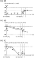
- FIGS. 8A to 8C depict examples of an envelope that is generated in the sound source LSI.
- the sound source LSI 370 includes a plurality of generator sections 371 (for example, corresponding to 256 channels), and a generator mixer 372 configured to adjust and mix waveform data that is output from each of the generator sections 371.
- Each of the generator sections 371 includes a waveform generator 373, a normal channel (normal line) 374 and a distortion channel (distortion line) 375.
- the waveform generator 373 is configured to determine and read out, from the plurality of pieces of waveform data stored in the ROM 330, waveform data corresponding to a musical instrument sound selected by the user at a reading speed corresponding to the key number of the pressed key 361, and to generate and output waveform data corresponding to the key number.
- the waveform data output from the waveform generator 373 is divided and input to the normal channel 374 and the distortion channel 375.
- the normal channel 374 includes a normal filter 3741, a normal filter envelope generator 3742, a normal amplifier 3743 and a normal amplifier envelope generator 3744. Meanwhile, in the below, as shown in FIG. 5 , the envelope generator is also denoted as "EG".
- the normal filter 3741 is configured to control a quality of sound corresponding to the waveform data input to the normal channel 374, in accordance with a filter envelope generated by the normal filter EG 3742 and indicating a temporal change in a cutoff frequency of a filter (for example, a low-pass filter).
- the normal amplifier 3743 is configured to control a level of sound corresponding to the waveform data, i.e., an amplitude of the waveform indicated by the waveform data, in accordance with an amplifier envelope generated by the normal amplifier EG 3744 and indicating a temporal change in a volume of sound (level).
- the distortion channel 375 includes an envelope detector 3751, an envelope calculator 3752, a normalization amplifier 3753, a distortion 3754, a distortion EG 3755, a distortion filter 3756, a distortion filter EG 3757, a distortion amplifier 3758, a distortion amplifier EG 3759, an inverse correction amplifier 3760 and a clipping control amplifier 3761.
- the envelope detector 3751 includes an absolute value circuit (full wave rectification circuit), a low-pass filter and the like, and is configured to detect an amplitude envelope of a waveform indicated by the waveform data (first waveform data (a)) input to the distortion channel 375, as shown in FIG. 6A .
- the envelope calculator 3752 is configured to adjust (normalize) amplitudes of the waveform indicated by the waveform data input to the distortion channel 375 to a constant amplitude, i.e., to calculate an amplifier envelope of which amplitudes of the waveform are kept without changing, based on the first amplitude envelope detected by the envelope detector 3751.
- the envelope calculator 3752 calculates an amplifier envelope of which waveform is amplified by 200% by the normalization amplifier 3753.
- the normalization amplifier 3753 is configured to normalize the amplitudes of the waveform, as shown in FIG. 6B , by multiplying the amplifier envelope calculated by the envelope calculator 3752 by the waveform indicated by the waveform data input to the distortion channel 375.
- processing executed by the normalization amplifier 3753 in which different first amplitudes of a first waveform indicated by the first waveform data as certain waveform data input to the distortion channel 375 are all changed to same second amplitude, is also referred to as normalize processing.
- waveform data indicative of a second waveform as the waveform of which amplitudes have been changed is also referred to as normalized data (b).
- the second amplitudes may be larger than the first amplitudes.
- the distortion 3754 includes a distortion gain amplifier 3754A and a clipper 3754B.
- the distortion gain amplifier 3754A is configured to amplify at least a part of the waveform (normalized data (b)) of which amplitudes have been normalized, as shown in FIGS. 6C and 7 , in accordance with an amplifier envelope (hereinbelow, referred to as "distortion envelope") generated by the distortion EG 3755 and indicating a temporal change of gain.
- b normalized data
- the clipper 3754B is configured to clip the amplified waveform (amplified data (c)), based on a setting value of a clipping level with respect to a positive region of the waveform, which is supplied from the CPU 310. More specifically, the clipper 3754B restricts amplitudes, which exceed a positive clipping level, of the amplitudes of the amplified waveform (amplified data (c)) to the positive clipping level.
- the clipping level is determined in accordance with the musical instrument sound selected by the user, and may be set for both a positive region and a negative region of a waveform. The clipping level may be set for at least one of the positive region and the negative region of the waveform.
- waveform data indicative of a third waveform as the clipped waveform is also referred to as clipped data (d).
- the distortion filter 3756 is configured to control a quality of sound corresponding to data of the clipped waveform, in accordance with a filter envelope generated by the distortion filter EG 3757.
- the distortion amplifier 3758 is configured to control a level of sound corresponding to the data of the clipped waveform, in accordance with an amplifier envelope generated by the distortion amplifier EG 3759 (hereinbelow, referred to as "distortion amplifier envelope"). As shown in FIG. 5 , the distortion amplifier envelope is further adjusted by the inverse correction amplifier 3760 that will be described later.
- Each of the EGs 3742, 3744, 3755, 3757 and 3759 as described above is configured to generate each envelope as shown in FIGS. 8A to 8C , based on parameters relating to each envelope and supplied from the CPU 310, upon the key pressing and upon the key release.
- the distortion EG 3755 generates a distortion envelope as shown in FIG. 8A .
- the parameters relating to each envelope include a parameter relating to target levels L0 to L4, a parameter relating to rates R1 to R4 for reaching the target levels, and the like.
- each of the EGs 3742, 3744, 3755, 3757 and 3759 may be supplied, from the CPU 310, with parameters including a release rate R4 of which gradient is set gentler as a value of the velocity is smaller, i.e., a key release speed is lower.
- the inverse correction (correction) amplifier 3760 is configured to adjust the distortion amplifier envelope so as to cancel an influence of the amplitude normalization by the normalization amplifier 3753, based on the amplitude envelope detected by the envelope detector 3751. For example, when a value of the amplitude envelope detected by the envelope detector 3751 is attenuated from a certain value by 50% and the waveform is amplified by 200% by the normalization amplifier 3753, the inverse correction amplifier 3760 attenuates the value of the distortion amplifier envelope by 50%. The amplitude envelope detected by the envelope detector 3751 is multiplied by the distortion amplifier envelope by the inverse correction amplifier 3760. A result thereof is also multiplied by the clipped waveform, as shown in FIG. 6E .
- amplitudes of the clipped waveform are corrected to the amplitudes of the waveform before the normalization. That is, the amplitudes of the third waveform indicated by the clipped data are changed in conformity to the first amplitudes of the first waveform as the waveform before the normalization, so that waveform data (e) indicative of a fourth waveform (corresponding to "distortion waveform” that will be described later) of which amplitudes have been changed is generated and output.
- the clipping control amplifier 3761 is configured to further adjust the distortion amplifier envelope adjusted by the inverse correction amplifier 3760, based on a setting value of gain supplied from the CPU 310. More specifically, the clipping control amplifier 3761 adjusts a gain of the distortion amplifier envelope, thereby adjusting an addition ratio of the distortion amplifier envelope to the distortion envelope. Thereby, the clipping control amplifier 3761 controls a degree of amplification by the distortion gain amplifier 3754A in the distortion 3754, and also controls indirectly a degree of clipping by the clipper 3754B. Therefore, the distortion 3754 can execute a feedback control of largely restricting the amplitudes as the values of the distortion amplifier envelope are larger, i.e., the amplitudes of the waveform are larger.
- the generator section 371 further includes a section mixer 377.
- the section mixer 377 is configured to adjust and mix the waveform data output from the normal amplifier 3743 (hereinbelow, referred to as "normal waveform data”) and the waveform data output from the distortion amplifier 3758 (hereinbelow, referred to as “distortion waveform data”) (so that a waveform shape of sound output from the electronic musical instrument 300 is to be the waveform shape exemplified in the first embodiment of FIG. 1B or the second embodiment of FIG. 2B , for example).
- the section mixer 377 may adjust (attenuate) each of the input normal waveform data and distortion waveform data to 50% and then may add the same.
- the section mixer 377 may adjust (attenuate) waveform data obtained by adding each of the normal waveform data and the distortion waveform data to 50%.
- the section mixer 377 may add first output waveform data in which the normal waveform data output from the normal amplifier 3743 has been changed in conformity to the envelope coinciding with the clipping level in the first embodiment of FIG. 1B or the second embodiment of FIG. 2B , for example, as the envelope generated by the normal amplifier EG, and second output waveform data output by the distortion amplifier 3758.
- the section mixer 377 is configured to output data of a waveform (added waveform) obtained by adding the normal waveform indicated by the normal waveform data and the distortion waveform indicated by the distortion waveform data. Thereby, the section mixer 377 can output the data of the added waveform corresponding to the distortion sound as a sound that simulates the contact sound.
- the section mixer 377 may be supplied, from the CPU 310, a setting value of the addition ratio corresponding to the musical instrument sound selected by the user, or may adjust the addition ratio of the normal waveform and the distortion waveform to a setting value of the addition ratio corresponding to the musical instrument sound.
- a setting value of the addition ratio corresponding to the acoustic piano 100 may be set to a small value, and data of an added waveform of which a degree of distortion is small may be output.
- the added waveform may be a waveform corresponding to a modest contact sound such as a sound that is generated when the soft damper 120 comes into contact with the string 130 in the acoustic piano 100 as shown in FIG. 1A .
- a setting value of the addition ratio corresponding to the guitar 200 may be set to a large value, and data of an added waveform of which a degree of distortion is large may be output.
- the added waveform may be a waveform corresponding to a contact sound in which higher harmonics are emphasized, such as a sound that is generated when the string 210 comes into contact with the rigid metal fret 220 in the guitar 200 as shown in FIG. 2A .
- a rough addition ratio of the normal waveform and the distortion waveform may be set as a fixed ratio, and a slight variation in the addition ratio over time may be reproduced by each of the EGs 3744 and 3759 and the like.
- the section mixer 377 may be supplied, from the CPU 310, with a setting value of the addition ratio corresponding to a velocity, and may adjust the addition ratio of the normal waveform and the distortion waveform to the setting value of the addition ratio corresponding to a velocity.
- the sound source LSI 370 may be configured to implement functions, in addition to the above-described functions, and may also be configured not to implement some of the above-described functions.
- the waveform generator 373 may be configured to execute loop processing of repeatedly reading out the waveform data from the ROM 330, thereby generating waveform data corresponding to a sustained sound.
- the waveform generator 373 may be configured to read out data of a waveform of which amplitudes have been already normalized from the ROM 330.
- the envelope detector 3751, the envelope calculator 3752, the normalization amplifier 3753, the inverse correction amplifier 3760 and the like may be omitted.
- the generator mixer 372 may be supplied, from the CPU 310, with a setting value of a level corresponding to a velocity or may adjust a value of a level of sound corresponding to each waveform data output from each generator section 371 to the setting value of a level corresponding to a velocity.
- FIGS. 8A to 8C depict examples of an envelope that is generated for an acoustic piano sound.
- the distortion EG 3755 generates a distortion envelope as shown in FIG. 8A
- the normal filter EG 3742 and the distortion filter EG 3757 generate a filter envelope as shown in FIG. 8B
- the normal amplifier EG 3744 and the distortion amplifier EG 3759 generate an amplifier envelope as shown in FIG. 8C .
- an absolute value of the clipping level is set to 1.0, in the example of FIG.
- a value of the threshold value envelope upon the key pressing is set to zero that is the minimum value, so that the contact sound is not generated upon the key pressing. Also, a value of the distortion envelope upon the key release is set to approximate 1.0 along the rates R3 and R4 over time.
- the distortion EG 3755 when the release is performed on the string 210, a sound of the string 210 coming into contact with the fret 220 or the like is generated, and the contact sound is difficult to be heard over time.
- the distortion EG 3755 generates a distortion envelope as shown in FIG. 9A
- the normal filter EG 3742 and the distortion filter EG 3757 generate a filter envelope as shown in FIG. 9B
- the normal amplifier EG 3744 and the distortion amplifier EG 3759 generate an amplifier envelope as shown in FIG. 9C .
- an absolute value of the clipping level is set to 1.0
- a value of the distortion envelope upon the key pressing is set to be less than 1.0
- the contact sound upon the key pressing is difficult to be generated.
- a value of the distortion envelope upon the key release is set to 1.0 or greater immediately after the key release, and is then set to be less than 1.0, so that the contact sound heard immediately after the key release is difficult to be heard over time.
- the addition ratio of the distortion envelope and distortion amplifier envelope corresponding to the sound of the guitar 200 may be set to about 1:0.6, for example.
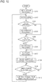
- FIG. 10 is a flowchart depicting a sequence of processing that is executed by the CPU.
- FIG. 11 is a subroutine flowchart depicting a sequence of sound source LSI control processing of step S108 in FIG. 10 .
- Algorithms shown in each flowchart are stored as programs in the ROM 330 or the like, and are executed by the CPU 310.
- the CPU 310 when a power supply becomes on, the CPU 310 first executes initialization processing on each constituent element of the electronic musical instrument 300 (step S101). Then, the CPU 310 executes user interface processing (UI processing) of displaying a variety of information on the LCD 350 or receiving a user operation via the switch panel 340 (step S 102). For example, the CPU 310 receives a user operation of selecting a certain musical instrument sound from the multiple musical instrument sounds, via the switch panel 340.
- UI processing user interface processing
- the CPU 310 determines whether the user has performed the key pressing (step S103).
- the CPU 310 executes key pressing processing (also referred to as "sound producing processing” or "note-on processing") (step S104).
- the key pressing processing includes processing of acquiring a key number and a velocity of the key 361 on which the key pressing has been performed, processing of assigning the generator section 371, and the like, for example.
- the key pressing processing includes control processing for causing the sound source LSI 370 to execute initialization and operation start of the waveform generator 373 in the assigned generator section 371, readout of the waveform data in the waveform generator 373 of which operation has started, initialization of each of the EGs 3742, 3744, 3755, 3757 and 3759, and the like.
- the operation of each of the EGs 3742, 3744, 3755, 3757 and 3759 is automatically started in EG steady processing of step S107, which will be described later.
- step S103 NO
- the CPU 310 proceeds to processing of step S105.
- the CPU 310 determines whether the user has performed the key release (step S105).
- step S105 determines whether the key release has been performed (step S105: YES).
- the CPU 310 executes key release processing (also referred to as “silencing processing ", “sound muffling processing” or “note-off processing”) (step S106).
- the key release processing includes processing of acquiring a key number and a velocity of the key 361 on which the key release has been performed, control processing of each of the EGs 3742, 3744, 3755, 3757 and 3759, and the like, for example.
- step S105 the CPU 310 executes, as the key release processing, processing of shifting each of the EGs 3742, 3744, 3755, 3757 and 3759 to a release state, for example.
- step S105 the CPU 310 proceeds to processing of step S107.
- the CPU 310 executes EG steady processing (step S107). More specifically, the CPU 310 supplies parameters corresponding to the selected musical instrument sound and the current state to each of the EGs 3742, 3744, 3755, 3757 and 3759, thereby executing processing of generating envelopes. Then, the CPU 310 executes sound source LSI control processing (step S108). The sound source LSI control processing will be described later in detail with reference to FIG. 11 .
- the CPU 310 determines whether a value counted by the timer counter 390 is equal to or greater than 1000 ⁇ sec, i.e., 1ms (step S109). When it is determined that the counted value is not equal to or greater than 1000 ⁇ sec, i.e., is less than 1000 ⁇ sec (step S109: NO), the CPU 310 stands by until the counted value becomes equal to or greater than 1000 ⁇ sec. On the other hand, when it is determined that the counted value is equal to or greater than 1000 ⁇ sec (step S109: YES), the CPU 310 subtracts 1000 ⁇ sec from the value counted by the timer counter 390 (step S110), and returns to the processing of step S102. That is, the CPU 310 executes the processing of step S109 and S110 so as to execute the processing from step S102 to S108 every 1000 ⁇ sec on average.
- step S108 the sound source LSI control processing of step S108 is described in detail.
- the CPU 310 controls the sound source LSI 370 to execute processing from step S201 to S206 shown in FIG. 11 .
- an envelope obtained by adding the distortion amplifier envelope and distortion envelope adjusted by the inverse correction amplifier 3760 and the clipping control amplifier 3761 is set to a gain of the distortion gain amplifier 3754A (step S201).
- a gain of the inverse correction amplifier 3760 corresponds to the amplitude envelope detected by the envelope detector 3751, as described above.
- the filter envelope generated by the distortion filter EG 3757 is set in the distortion filter 3756 (step S202). Also, the distortion amplifier envelope adjusted by the inverse correction amplifier 3760 is set in the distortion amplifier 3758 (step S203). Also, the filter envelope generated by the normal filter EG 3742 is set in the normal filter 3741 (step S204), and the amplifier envelope generated by the normal amplifier EG 3744 is set in the normal amplifier 3743 (step S205).
- step S206 it is determined whether all the values of the amplifier envelope supplied to the normal amplifier 3743 and the distortion amplifier 3758 have reached zero and the operations of both the normal amplifier 3743 and the distortion amplifier 3758 have stopped.
- step S206 When it is determined that the operations of both the amplifiers 3743 and 3758 have stopped (step S206: YES), the operation of the waveform generator 373 is also stopped (step S207), and the sound source LSI control processing is over. On the other hand, when it is determined that the operation of any one of both the amplifiers 3743 and 3758 has not stopped (step S206: NO), the sound source LSI control processing is over.
- the present embodiment achieves following effects.
- the electronic musical instrument 300 generates the normalized data indicative of the second waveform by the normalize processing of changing the different first amplitudes of the first waveform indicated by the first waveform data as certain waveform data input to the distortion channel 375 to the same second amplitude. Then, the electronic musical instrument 300 amplifies at least a part of the second waveform indicated by the normalized data, and clips the amplified waveform by a certain clipping level to generate the clipped data indicative of the third waveform. Also, the electronic musical instrument 300 changes the amplitudes of the third waveform indicated by the clipped data in conformity to the first amplitudes of the first waveform, thereby generating and outputting the waveform data indicative of the fourth waveform.
- the waveform data indicative of the output fourth waveform is mixed with the waveform data output from the normal amplifier 3743 in the normal channel 374 by the section mixer 377.
- the electronic musical instrument 300 can generate the distortion sound corresponding to the waveform of which amplitudes are restricted, as a sound that simulates the contact sound, and can reproduce the contact sound of the string that is generated in the musical instrument with strings and changes over time and in accordance with a playing method and the like.
- the electronic musical instrument 300 detects the amplitude envelope of the first waveform before the normalize processing, and multiplies the value calculated based on the detected amplitude envelope by the first waveform, thereby changing the first amplitudes of the first waveform to the second amplitudes. Thereby, the electronic musical instrument 300 can normalize the amplitudes of the original waveform simply by executing the multiplication processing that is relatively simple signal processing.
- the electronic musical instrument 300 multiplies the value calculated based on the detected amplitude envelope by the third waveform indicated by the clipped data, thereby changing the amplitudes of the third waveform in conformity to the first amplitudes. Thereby, the electronic musical instrument 300 can correct the amplitudes of the clipped waveform to the amplitudes of the waveform before the normalization simply by executing the multiplication processing that is relatively simple signal processing.
- the second amplitudes are larger than the first amplitudes.
- the electronic musical instrument 300 can change the different first amplitudes of the first waveform to the second amplitudes larger than the first amplitudes.
- the clipping level is set, in accordance with the musical instrument sound, which is selected by the user, from the multiple musical instrument sounds.
- the electronic musical instrument 300 can favorably reproduce the contact sound that is different for each musical instrument.
- the electronic musical instrument 300 adds (mixes) the normal waveform and the distortion waveform with the set addition ratio. Thereby, the electronic musical instrument 300 can output the data of the waveforms added with the diverse addition ratios. Therefore, the electronic musical instrument 300 can favorably reproduce the contact sound of the soft damper 120 coming into contact with the string 130 in the acoustic piano 100 and the contact sound of the string 210 coming into contact with the rigid metal fret 220 in the guitar 200, for example.
- the parameter, the setting value and the like corresponding to the velocity are supplied from the CPU 310 to the sound source LSI 370.
- a parameter, a setting value and the like corresponding to an element other than the velocity may be supplied to the sound source LSI 370.
- the element other than the velocity after-touch that can be detected by a pressure sensor or the like may be exemplified.
- the processing shown in FIG. 11 is executed by the CPU 310. However, at least some of the processing shown in FIG. 11 may be executed by the sound source LSI 370.
- the contact sounds that are generated in the acoustic piano 100 and the guitar 200 are reproduced in the electronic musical instrument 300.
- contact sounds that are generated in other musical instruments with strings may also be reproduced.
- folk musical instruments such as sitar having a contact plate (bridge), a fretless bass, and the like may be exemplified.
- the electronic musical instrument 300 may control the value of the clipping level to a small value for a long time period, for example.
- the contact sounds that are generated in the musical instruments with strings are reproduced in the electronic musical instrument 300.
- the contact sounds may be reproduced in other instruments.
- a PC and the like that are used for music production may be exemplified.
- the present disclosure is not limited to the above-described embodiment, and can be diversely modified without departing from the gist thereof, in the implementation phase.
- the functions that are executed in the above-described embodiment may be implemented with being combined appropriately as much as possible.
- the above-described embodiment includes inventions of diverse stages, and various inventions can be extracted by combining appropriately a plurality of constituent elements disclosed in the embodiment. For example, even if some constituent elements are omitted from all the constituent elements disclosed in the embodiment, the resultant configuration can be extracted as an invention, inasmuch as the effects can be achieved.
Landscapes
- Physics & Mathematics (AREA)
- Engineering & Computer Science (AREA)
- Acoustics & Sound (AREA)
- Multimedia (AREA)
- Nonlinear Science (AREA)
- General Engineering & Computer Science (AREA)
- Electrophonic Musical Instruments (AREA)
Abstract
Description
- The present disclosure relates to an electronic musical instrument, a method and a program.
- In the related art, a variety of technologies for reproducing sounds of musical instruments with strings, including an acoustic piano, a guitar and the like, in an electronic musical instrument are developed. In the musical instruments with strings, a sound that is generated as a result of contact of the vibrating string with another object is also generated. Therefore, also in the electronic musical instruments, it is attempted to reproduce such contact sound.
- For example,
JP-A-2011-154394 - According to the technology disclosed in
JP-A-2011-154394 - An electronic musical instrument related to one aspect of the present disclosure includes: means for determining, in accordance with a user operation on at least one operation element, first waveform data from a plurality of pieces of waveform data, the first waveform data including multiple first waveforms having different first amplitudes; means for generating normalized data that includes multiple second waveforms having same second amplitude, based on the first waveform data; means for amplifying the second amplitude of at least one of the multiple second waveforms in the normalized data to generate amplified data; means for clipping at least one waveform included in the amplified data at a certain clipping level to generate clipped data that includes multiple third waveforms; and means for changing amplitudes of the multiple third waveforms in the clipped data to the different first amplitudes to generate waveform data that includes multiple fourth waveforms.
- According to the present disclosure, it is possible to favorably reproduce a contact sound that is generated when playing the acoustic musical instrument.
-
-
FIG. 1A is a view for illustrating a contact sound that is generated in an acoustic piano; -
FIG. 1B is a view for illustrating Comparative Example where a contact sound that is generated in the acoustic piano is not reproduced, and an embodiment of the present disclosure where the contact sound is reproduced; -
FIG. 2A is a view for illustrating a contact sound that is generated in a guitar; -
FIG. 2B is a view for illustrating Comparative Example where a contact sound that is generated in the guitar is not reproduced, and an embodiment of the present disclosure where the contact sound is reproduced; -
FIG. 3 depicts an example of an outer shape of an electronic musical instrument in accordance with an embodiment of the present disclosure; -
FIG. 4 is a block diagram depicting a hardware configuration of the electronic musical instrument; -
FIG. 5 is a block diagram depicting a schematic configuration of a sound source LSI; -
FIG. 6 is a view for illustrating processing that is executed in a distortion channel; -
FIG. 7 is a block diagram depicting a schematic configuration of a distortion in the sound source LSI; -
FIG. 8A depicts an example of an envelope for generating a piano sound; -
FIG. 8B depicts an example of the envelope for generating the piano sound; -
FIG. 8C depicts an example of the envelope for generating the piano sound; -
FIG. 9A depicts an example of an envelope for generating a guitar sound; -
FIG. 9B depicts an example of the envelope for generating the guitar sound; -
FIG. 9C depicts an example of the envelope for generating the guitar sound; -
FIG. 10 is a flowchart depicting a sequence of processing that is executed by a CPU; and -
FIG. 11 is a subroutine flowchart depicting a sequence of sound source LSI control processing of step S108 inFIG. 10 . - Hereinbelow, after describing the principle of the present disclosure, embodiments based on the principle of the present disclosure will be described with reference to the accompanying drawings.
- In the description of the drawings, the same elements are denoted with the same reference signs, and the overlapping descriptions are omitted. Also, for convenience of descriptions, the dimensional ratios in the drawings may be different from the actual ratios due to exaggerated illustrations.
- First, in a musical instrument with strings, a cause of a contact sound that is generated as a result of contact of the vibrating string with another object, and an output image of a waveform including the contact sound are described.
-
FIG. 1A is a view for illustrating a contact sound that is generated in an acoustic piano.FIG. 1B illustrates an output image diagram of a waveform that does not include a contact sound generated in the acoustic piano (Comparative Example), and an output image diagram of a waveform that includes the contact sound (first embodiment). - In an
acoustic piano 100 as shown inFIG. 1A , when akey 110 is released, adamper 120 comes into contact with astring 130, so that vibration of thestring 130 is attenuated. Even when felt used for thedamper 120 is made of a soft material, the felt applies a larger resistance to thestring 130, as compared to the air. Therefore, when thedamper 120 comes into contact with thestring 130, the vibration of thestring 130 is irregularly attenuated, so that a contact sound is generated. While an amplitude of thestring 130 is large, thedamper 120 is bounced (jumped up) by thestring 130 and cannot be thus in contact with thestring 130 for a long time. However, as the amplitude of thestring 130 becomes smaller over time, a time period for which thedamper 120 is in contact with thestring 130 becomes longer, and the contact sound is emphasized among sounds being produced. - In an electronic musical instrument configured to reproduce sounds of the
acoustic piano 100, as shown in an upper drawing ofFIG. 1B (Comparative Example), a level of sound, i.e., an amplitude of a waveform upon the key release is controlled so as to change over time, in accordance with an envelope that reproduces an envelope of amplitudes of thestring 130 upon the key release. However, in the electronic musical instrument of the related art, the change in contact sound over time as described above is not reproduced. Therefore, in an electronic musical instrument of the present embodiment, as shown in a lower drawing ofFIG. 1B (the first embodiment of the present disclosure), amplitudes of a waveform are restricted when the amplitudes exceed certain levels (levels of a broken line) indicating threshold values of generation of the contact sound, and a distortion sound corresponding to a waveform of which amplitudes are restricted is thus generated as a sound that simulates the contact sound. For example, amplitudes of a waveform corresponding to a sound upon the key release of theacoustic piano 100 are controlled so as to be largely restricted over time. Also, the distortion sound as the contact sound is controlled so as to be further emphasized as a time period k1, a time period k2, and a time period k3 progress, as shown in the lower drawing ofFIG. 1B , for example (a difference value between the threshold value of the broken line and a solid line value of the solid line indicative of an amplitude envelope gradually increases as the time period k1, the time period k2, and the time period k3 progress, so that the amplitudes of the waveform are largely restricted over time and the contact sound that is the distortion sound is further emphasized over time). Therefore, it is possible to favorably reproduce the contact sound of thedamper 120 and thestring 130, which is generated upon the key release in theacoustic piano 100. -
FIG. 2A is a view for illustrating a contact sound that is generated in a guitar.FIG. 2B is an output image diagram of a waveform that does not include a contact sound generated in the guitar (Comparative Example), and an output image diagram of a waveform that includes the contact sound (second embodiment). - Also in plucked string instruments such as a
guitar 200 as shown inFIG. 2A , when a string release where a player's finger F releases from astring 210 is performed, a contact sound is generated. More specifically, while the finger F presses thestring 210, the contact sound is not generated because thestring 210 vibrates about a fret 220 as a support point. However, when the finger F starts to move away from thefret 220, the support point of thestring 210 moves from thefret 220 to the finger F, so that thestring 210 vibrates about the finger F as a support point. When thestring 210 comes into contact with thefret 220 or the like, the contact sound is generated. For this reason, in theguitar 200, the contact sound starts to be heard immediately after the string releases, unlike theacoustic piano 100. Then, as the amplitude of thestring 210 becomes smaller over time or the finger F moves away from thefret 220, the contact sound becomes difficult to be heard. - In the electronic musical instrument configured to reproduce sounds of the
guitar 200, as shown in an upper drawing ofFIG. 2B , a level of sound, i.e., an amplitude of a waveform upon the key release is controlled so as to change over time, in accordance with an envelope that reproduces an envelope of amplitudes of thestring 210 upon the key release. More specifically, the amplitude of the waveform is controlled so as to increase over time during a time period k4 immediately after the key release of the electronic musical instrument, i.e., immediately after the string release of theguitar 200, and to attenuate over time during time periods k5 and k6 thereafter, for example. Also, a clipping level is set as shown in a lower drawing ofFIG. 2B , for example. The distortion sound as the contact sound is controlled so that it is emphasized over time during the time period k4 (because the difference value between the threshold value of the broken line and the solid line value of the solid line becomes gradually larger), is attenuated over time during the time period k5 (because the difference value between the threshold value of the broken line and the solid line value of the solid line becomes gradually smaller), and is not heard during the time period k6 (because the solid line value has not reached the threshold value). Thereby, it is possible to favorably reproduce the contact sound that is generated when thestring 210 comes into contact with the fret or the like upon the key release in theguitar 200. - In the below, a configuration, processing and the like of the electronic musical instrument configured to reproduce the contact sounds as described above are described with reference to the drawings.
-
FIG. 3 depicts an example of an outer shape of an electronic musical instrument in accordance with an embodiment of the present disclosure.FIG. 4 is a block diagram depicting a hardware configuration of the electronic musical instrument. - As shown in
FIGS. 3 and4 , an electronicmusical instrument 300 includes a CPU (Central Processing Unit) 310, a RAM (Random Access Memory) 320, a ROM (Read Only Memory) 330, aswitch panel 340, an LCD (liquid crystal monitor) 350, akeyboard 360, a sound source LSI (large-scale integration) 370, a D/A converter 380, anamplifier 385 and atimer counter 390. TheCPU 310, theRAM 320, theROM 330 and thesound source LSI 370 are each connected to abus 395. Also, theswitch panel 340, theLCD 350 and thekeyboard 360 are each connected to thebus 395 via each of an I/O interface 345, anLCD controller 355 and akey scanner 365. - The
CPU 310 as a processor is configured to control the respective constituent elements and to execute a variety of calculation processing, in accordance with programs. TheRAM 320 is configured to temporarily store programs, data and the like, as a work area. - The
ROM 330 as a memory has a program area and a data area, and stores a variety of programs, data and the like in advance. TheROM 330 is configured to store a plurality of pieces of waveform data corresponding to multiple musical instrument sounds, as a waveform memory, for example. - The
switch panel 340 includes a plurality of switches 341, and is configured to receive a user operation of pressing each of the plurality of switches 341. For example, theswitch panel 340 includes the plurality of switches 341 corresponding to multiple musical instrument sounds, and receives a user operation of selecting a certain musical instrument sound from the multiple musical instrument sounds. The I/O interface 345 is configured to monitor each of the plurality of switches 341 of theswitch panel 340, and, when it is detected that each of the plurality of switches 341 is pressed, notifies the detection to theCPU 310. - The
LCD 350 is configured to display a variety of information. TheLCD controller 355 is an IC (integrated circuit) configured to control theLCD 350. - The
keyboard 360 has a plurality ofkeys 361 as operation elements, and is configured to receive user operations of pressing and releasing the keys, as a user operation. Each of the plurality ofkeys 361 is configured to operate at one end of a leaf spring or the like, as a support point, and may include a plurality of switches (contact points) that is sequentially turned on or off by the key pressing or the key release. - The
key scanner 365 is configured to monitor each of the plurality ofkeys 361 of thekeyboard 360, and to detect whether each of the plurality ofkeys 361 is pressed or released. When the key pressing is detected, thekey scanner 365 detects and notifies, to theCPU 310, a key number (note number) of the pressed key 361, and a velocity upon the key pressing corresponding to a key pressing speed. Also, when the key release is detected, thekey scanner 365 detects and notifies, to theCPU 310, a key number of the released key 361, and a velocity upon the key release corresponding to a key release speed. Thekey scanner 365 may detect the velocity upon the key pressing or upon the key release by measuring a difference between times at which at least two switches of each of the plurality ofkeys 361 are detected to be on or off. - The
sound source LSI 370 as a processor adopts a well-known waveform memory reading method, and is configured to read out and process waveform data corresponding to a musical instrument sound selected by the user from theROM 330, and to output the same to the D/A converter 380. Thesound source LSI 370 will be described later in detail with reference toFIG. 5 . - The D/
A converter 380 is configured to convert digital waveform data output from thesound source LSI 370 into analog waveform signals, and to output the same to theamplifier 385. Theamplifier 385 is configured to amplify the analog waveform signals output from the D/A converter 380, and to output the same to a speaker, an output terminal or the like (not shown). - The
timer counter 390 includes a counter configured to increment a value every 1µsec, for example, and is configured to measure time. - In the meantime, the electronic
musical instrument 300 may include a constituent element, in addition to the above-described constituent elements, and may not include some of the above-described constituent elements. - Subsequently, the
sound source LSI 370 is described in detail.FIG. 5 is a block diagram depicting a schematic configuration of the sound source LSI.FIG. 6 is a view for illustrating processing that is executed in a distortion channel.FIG. 7 is a block diagram depicting a schematic configuration of a distortion in the sound source LSI.FIGS. 8A to 8C depict examples of an envelope that is generated in the sound source LSI. - As shown in
FIG. 5 , thesound source LSI 370 includes a plurality of generator sections 371 (for example, corresponding to 256 channels), and agenerator mixer 372 configured to adjust and mix waveform data that is output from each of thegenerator sections 371. Each of thegenerator sections 371 includes awaveform generator 373, a normal channel (normal line) 374 and a distortion channel (distortion line) 375. - The
waveform generator 373 is configured to determine and read out, from the plurality of pieces of waveform data stored in theROM 330, waveform data corresponding to a musical instrument sound selected by the user at a reading speed corresponding to the key number of the pressed key 361, and to generate and output waveform data corresponding to the key number. The waveform data output from thewaveform generator 373 is divided and input to thenormal channel 374 and thedistortion channel 375. - The
normal channel 374 includes anormal filter 3741, a normalfilter envelope generator 3742, anormal amplifier 3743 and a normalamplifier envelope generator 3744. Meanwhile, in the below, as shown inFIG. 5 , the envelope generator is also denoted as "EG". Thenormal filter 3741 is configured to control a quality of sound corresponding to the waveform data input to thenormal channel 374, in accordance with a filter envelope generated by thenormal filter EG 3742 and indicating a temporal change in a cutoff frequency of a filter (for example, a low-pass filter). Thenormal amplifier 3743 is configured to control a level of sound corresponding to the waveform data, i.e., an amplitude of the waveform indicated by the waveform data, in accordance with an amplifier envelope generated by thenormal amplifier EG 3744 and indicating a temporal change in a volume of sound (level). - The
distortion channel 375 includes anenvelope detector 3751, anenvelope calculator 3752, anormalization amplifier 3753, adistortion 3754, adistortion EG 3755, adistortion filter 3756, adistortion filter EG 3757, adistortion amplifier 3758, adistortion amplifier EG 3759, aninverse correction amplifier 3760 and aclipping control amplifier 3761. - The
envelope detector 3751 includes an absolute value circuit (full wave rectification circuit), a low-pass filter and the like, and is configured to detect an amplitude envelope of a waveform indicated by the waveform data (first waveform data (a)) input to thedistortion channel 375, as shown inFIG. 6A . Theenvelope calculator 3752 is configured to adjust (normalize) amplitudes of the waveform indicated by the waveform data input to thedistortion channel 375 to a constant amplitude, i.e., to calculate an amplifier envelope of which amplitudes of the waveform are kept without changing, based on the first amplitude envelope detected by theenvelope detector 3751. For example, when a value of the first amplitude envelope detected by theenvelope detector 3751 is attenuated from a certain value by 50%, theenvelope calculator 3752 calculates an amplifier envelope of which waveform is amplified by 200% by thenormalization amplifier 3753. Thenormalization amplifier 3753 is configured to normalize the amplitudes of the waveform, as shown inFIG. 6B , by multiplying the amplifier envelope calculated by theenvelope calculator 3752 by the waveform indicated by the waveform data input to thedistortion channel 375. Meanwhile, in the below, processing executed by thenormalization amplifier 3753, in which different first amplitudes of a first waveform indicated by the first waveform data as certain waveform data input to thedistortion channel 375 are all changed to same second amplitude, is also referred to as normalize processing. Also, waveform data indicative of a second waveform as the waveform of which amplitudes have been changed is also referred to as normalized data (b). The second amplitudes may be larger than the first amplitudes. - As shown in
FIG. 7 , thedistortion 3754 includes adistortion gain amplifier 3754A and aclipper 3754B. Thedistortion gain amplifier 3754A is configured to amplify at least a part of the waveform (normalized data (b)) of which amplitudes have been normalized, as shown inFIGS. 6C and7 , in accordance with an amplifier envelope (hereinbelow, referred to as "distortion envelope") generated by thedistortion EG 3755 and indicating a temporal change of gain. As shown inFIGS. 6D and7 , theclipper 3754B is configured to clip the amplified waveform (amplified data (c)), based on a setting value of a clipping level with respect to a positive region of the waveform, which is supplied from theCPU 310. More specifically, theclipper 3754B restricts amplitudes, which exceed a positive clipping level, of the amplitudes of the amplified waveform (amplified data (c)) to the positive clipping level. The clipping level is determined in accordance with the musical instrument sound selected by the user, and may be set for both a positive region and a negative region of a waveform. The clipping level may be set for at least one of the positive region and the negative region of the waveform. Meanwhile, in the below, waveform data indicative of a third waveform as the clipped waveform is also referred to as clipped data (d). - The
distortion filter 3756 is configured to control a quality of sound corresponding to data of the clipped waveform, in accordance with a filter envelope generated by thedistortion filter EG 3757. Thedistortion amplifier 3758 is configured to control a level of sound corresponding to the data of the clipped waveform, in accordance with an amplifier envelope generated by the distortion amplifier EG 3759 (hereinbelow, referred to as "distortion amplifier envelope"). As shown inFIG. 5 , the distortion amplifier envelope is further adjusted by theinverse correction amplifier 3760 that will be described later. - Each of the
EGs FIGS. 8A to 8C , based on parameters relating to each envelope and supplied from theCPU 310, upon the key pressing and upon the key release. For example, thedistortion EG 3755 generates a distortion envelope as shown inFIG. 8A . - The parameters relating to each envelope include a parameter relating to target levels L0 to L4, a parameter relating to rates R1 to R4 for reaching the target levels, and the like. When the value of the amplifier envelope supplied to the
normal amplifier 3743 and thedistortion amplifier 3758 becomes zero and operations of thenormal amplifier 3743 and thedistortion amplifier 3758 are thus stopped, an operation of thewaveform generator 373 is also stopped. In the meantime, each of theEGs CPU 310 or may generate each envelope corresponding to the velocity. For example, each of theEGs CPU 310, with parameters including a release rate R4 of which gradient is set gentler as a value of the velocity is smaller, i.e., a key release speed is lower. - The inverse correction (correction)
amplifier 3760 is configured to adjust the distortion amplifier envelope so as to cancel an influence of the amplitude normalization by thenormalization amplifier 3753, based on the amplitude envelope detected by theenvelope detector 3751. For example, when a value of the amplitude envelope detected by theenvelope detector 3751 is attenuated from a certain value by 50% and the waveform is amplified by 200% by thenormalization amplifier 3753, theinverse correction amplifier 3760 attenuates the value of the distortion amplifier envelope by 50%. The amplitude envelope detected by theenvelope detector 3751 is multiplied by the distortion amplifier envelope by theinverse correction amplifier 3760. A result thereof is also multiplied by the clipped waveform, as shown inFIG. 6E . Thereby, amplitudes of the clipped waveform are corrected to the amplitudes of the waveform before the normalization. That is, the amplitudes of the third waveform indicated by the clipped data are changed in conformity to the first amplitudes of the first waveform as the waveform before the normalization, so that waveform data (e) indicative of a fourth waveform (corresponding to "distortion waveform" that will be described later) of which amplitudes have been changed is generated and output. - The
clipping control amplifier 3761 is configured to further adjust the distortion amplifier envelope adjusted by theinverse correction amplifier 3760, based on a setting value of gain supplied from theCPU 310. More specifically, theclipping control amplifier 3761 adjusts a gain of the distortion amplifier envelope, thereby adjusting an addition ratio of the distortion amplifier envelope to the distortion envelope. Thereby, theclipping control amplifier 3761 controls a degree of amplification by thedistortion gain amplifier 3754A in thedistortion 3754, and also controls indirectly a degree of clipping by theclipper 3754B. Therefore, thedistortion 3754 can execute a feedback control of largely restricting the amplitudes as the values of the distortion amplifier envelope are larger, i.e., the amplitudes of the waveform are larger. - The
generator section 371 further includes asection mixer 377. Thesection mixer 377 is configured to adjust and mix the waveform data output from the normal amplifier 3743 (hereinbelow, referred to as "normal waveform data") and the waveform data output from the distortion amplifier 3758 (hereinbelow, referred to as "distortion waveform data") (so that a waveform shape of sound output from the electronicmusical instrument 300 is to be the waveform shape exemplified in the first embodiment ofFIG. 1B or the second embodiment ofFIG. 2B , for example). Specifically, for example, thesection mixer 377 may adjust (attenuate) each of the input normal waveform data and distortion waveform data to 50% and then may add the same. Alternatively, thesection mixer 377 may adjust (attenuate) waveform data obtained by adding each of the normal waveform data and the distortion waveform data to 50%. Alternatively, thesection mixer 377 may add first output waveform data in which the normal waveform data output from thenormal amplifier 3743 has been changed in conformity to the envelope coinciding with the clipping level in the first embodiment ofFIG. 1B or the second embodiment ofFIG. 2B , for example, as the envelope generated by the normal amplifier EG, and second output waveform data output by thedistortion amplifier 3758. Thesection mixer 377 is configured to output data of a waveform (added waveform) obtained by adding the normal waveform indicated by the normal waveform data and the distortion waveform indicated by the distortion waveform data. Thereby, thesection mixer 377 can output the data of the added waveform corresponding to the distortion sound as a sound that simulates the contact sound. - The
section mixer 377 may be supplied, from theCPU 310, a setting value of the addition ratio corresponding to the musical instrument sound selected by the user, or may adjust the addition ratio of the normal waveform and the distortion waveform to a setting value of the addition ratio corresponding to the musical instrument sound. For example, a setting value of the addition ratio corresponding to theacoustic piano 100 may be set to a small value, and data of an added waveform of which a degree of distortion is small may be output. The added waveform may be a waveform corresponding to a modest contact sound such as a sound that is generated when thesoft damper 120 comes into contact with thestring 130 in theacoustic piano 100 as shown inFIG. 1A . Also, a setting value of the addition ratio corresponding to theguitar 200 may be set to a large value, and data of an added waveform of which a degree of distortion is large may be output. The added waveform may be a waveform corresponding to a contact sound in which higher harmonics are emphasized, such as a sound that is generated when thestring 210 comes into contact with the rigid metal fret 220 in theguitar 200 as shown inFIG. 2A . - Also, in the
section mixer 377, a rough addition ratio of the normal waveform and the distortion waveform may be set as a fixed ratio, and a slight variation in the addition ratio over time may be reproduced by each of theEGs section mixer 377 may be supplied, from theCPU 310, with a setting value of the addition ratio corresponding to a velocity, and may adjust the addition ratio of the normal waveform and the distortion waveform to the setting value of the addition ratio corresponding to a velocity. - In the meantime, the
sound source LSI 370 may be configured to implement functions, in addition to the above-described functions, and may also be configured not to implement some of the above-described functions. For example, thewaveform generator 373 may be configured to execute loop processing of repeatedly reading out the waveform data from theROM 330, thereby generating waveform data corresponding to a sustained sound. Also, thewaveform generator 373 may be configured to read out data of a waveform of which amplitudes have been already normalized from theROM 330. In this case, theenvelope detector 3751, theenvelope calculator 3752, thenormalization amplifier 3753, theinverse correction amplifier 3760 and the like may be omitted. Also, thegenerator mixer 372 may be supplied, from theCPU 310, with a setting value of a level corresponding to a velocity or may adjust a value of a level of sound corresponding to each waveform data output from eachgenerator section 371 to the setting value of a level corresponding to a velocity. - Subsequently, examples of the envelope that is generated by each of the
EGs FIGS. 8A to 8C depict examples of an envelope that is generated for an acoustic piano sound.FIGS. 9A to 9C depict examples of an envelope that is generated for a guitar sound. - As described above, in the
acoustic piano 100 as shown inFIG. 1A , when the key release is performed on the key 110, a sound of thedamper 120 coming into contact with thestring 130 is generated, and a ratio of the contact sound in the sound being produced increases over time. In order to favorably reproduce the phenomenon, for example, thedistortion EG 3755 generates a distortion envelope as shown inFIG. 8A , thenormal filter EG 3742 and thedistortion filter EG 3757 generate a filter envelope as shown inFIG. 8B , and thenormal amplifier EG 3744 and thedistortion amplifier EG 3759 generate an amplifier envelope as shown inFIG. 8C . In a case where an absolute value of the clipping level is set to 1.0, in the example ofFIG. 8A , a value of the threshold value envelope upon the key pressing is set to zero that is the minimum value, so that the contact sound is not generated upon the key pressing. Also, a value of the distortion envelope upon the key release is set to approximate 1.0 along the rates R3 and R4 over time. - Also, in the
guitar 200 as shown inFIG. 2A , when the release is performed on thestring 210, a sound of thestring 210 coming into contact with thefret 220 or the like is generated, and the contact sound is difficult to be heard over time. In order to favorably reproduce the phenomenon, thedistortion EG 3755 generates a distortion envelope as shown inFIG. 9A , thenormal filter EG 3742 and thedistortion filter EG 3757 generate a filter envelope as shown inFIG. 9B , and thenormal amplifier EG 3744 and thedistortion amplifier EG 3759 generate an amplifier envelope as shown inFIG. 9C . In a case where an absolute value of the clipping level is set to 1.0, when a value of the distortion envelope upon the key pressing is set to be less than 1.0, as shown inFIG. 9C , the contact sound upon the key pressing is difficult to be generated. Also, a value of the distortion envelope upon the key release is set to 1.0 or greater immediately after the key release, and is then set to be less than 1.0, so that the contact sound heard immediately after the key release is difficult to be heard over time. In the meantime, the addition ratio of the distortion envelope and distortion amplifier envelope corresponding to the sound of theguitar 200 may be set to about 1:0.6, for example. - Subsequently, processing that is executed by the
CPU 310 is described in detail.FIG. 10 is a flowchart depicting a sequence of processing that is executed by the CPU.FIG. 11 is a subroutine flowchart depicting a sequence of sound source LSI control processing of step S108 inFIG. 10 . Algorithms shown in each flowchart are stored as programs in theROM 330 or the like, and are executed by theCPU 310. - As shown in
FIG. 10 , when a power supply becomes on, theCPU 310 first executes initialization processing on each constituent element of the electronic musical instrument 300 (step S101). Then, theCPU 310 executes user interface processing (UI processing) of displaying a variety of information on theLCD 350 or receiving a user operation via the switch panel 340 (step S 102). For example, theCPU 310 receives a user operation of selecting a certain musical instrument sound from the multiple musical instrument sounds, via theswitch panel 340. - Subsequently, the
CPU 310 determines whether the user has performed the key pressing (step S103). When it is determined that the key pressing has been performed (step S103: YES), theCPU 310 executes key pressing processing (also referred to as "sound producing processing" or "note-on processing") (step S104). The key pressing processing includes processing of acquiring a key number and a velocity of the key 361 on which the key pressing has been performed, processing of assigning thegenerator section 371, and the like, for example. Also, the key pressing processing includes control processing for causing thesound source LSI 370 to execute initialization and operation start of thewaveform generator 373 in the assignedgenerator section 371, readout of the waveform data in thewaveform generator 373 of which operation has started, initialization of each of theEGs EGs CPU 310 proceeds to processing of step S105. - Subsequently, the
CPU 310 determines whether the user has performed the key release (step S105). When it is determined that the key release has been performed (step S105: YES), theCPU 310 executes key release processing (also referred to as "silencing processing ", "sound muffling processing" or "note-off processing") (step S106). The key release processing includes processing of acquiring a key number and a velocity of the key 361 on which the key release has been performed, control processing of each of theEGs CPU 310 executes, as the key release processing, processing of shifting each of theEGs CPU 310 proceeds to processing of step S107. - Subsequently, the
CPU 310 executes EG steady processing (step S107). More specifically, theCPU 310 supplies parameters corresponding to the selected musical instrument sound and the current state to each of theEGs CPU 310 executes sound source LSI control processing (step S108). The sound source LSI control processing will be described later in detail with reference toFIG. 11 . - Subsequently, the
CPU 310 determines whether a value counted by thetimer counter 390 is equal to or greater than 1000µsec, i.e., 1ms (step S109). When it is determined that the counted value is not equal to or greater than 1000µsec, i.e., is less than 1000µsec (step S109: NO), theCPU 310 stands by until the counted value becomes equal to or greater than 1000µsec. On the other hand, when it is determined that the counted value is equal to or greater than 1000µsec (step S109: YES), theCPU 310 subtracts 1000µsec from the value counted by the timer counter 390 (step S110), and returns to the processing of step S102. That is, theCPU 310 executes the processing of step S109 and S110 so as to execute the processing from step S102 to S108 every 1000µsec on average. - Subsequently, the sound source LSI control processing of step S108 is described in detail. The
CPU 310 controls thesound source LSI 370 to execute processing from step S201 to S206 shown inFIG. 11 . - More specifically, as shown in
FIG. 11 , in thesound source LSI 370, an envelope obtained by adding the distortion amplifier envelope and distortion envelope adjusted by theinverse correction amplifier 3760 and theclipping control amplifier 3761 is set to a gain of thedistortion gain amplifier 3754A (step S201). In the meantime, a gain of theinverse correction amplifier 3760 corresponds to the amplitude envelope detected by theenvelope detector 3751, as described above. - Also, the filter envelope generated by the
distortion filter EG 3757 is set in the distortion filter 3756 (step S202). Also, the distortion amplifier envelope adjusted by theinverse correction amplifier 3760 is set in the distortion amplifier 3758 (step S203). Also, the filter envelope generated by thenormal filter EG 3742 is set in the normal filter 3741 (step S204), and the amplifier envelope generated by thenormal amplifier EG 3744 is set in the normal amplifier 3743 (step S205). - Then, it is determined whether all the values of the amplifier envelope supplied to the
normal amplifier 3743 and thedistortion amplifier 3758 have reached zero and the operations of both thenormal amplifier 3743 and thedistortion amplifier 3758 have stopped (step S206). - When it is determined that the operations of both the
amplifiers waveform generator 373 is also stopped (step S207), and the sound source LSI control processing is over. On the other hand, when it is determined that the operation of any one of both theamplifiers - The present embodiment achieves following effects.
- The electronic
musical instrument 300 generates the normalized data indicative of the second waveform by the normalize processing of changing the different first amplitudes of the first waveform indicated by the first waveform data as certain waveform data input to thedistortion channel 375 to the same second amplitude. Then, the electronicmusical instrument 300 amplifies at least a part of the second waveform indicated by the normalized data, and clips the amplified waveform by a certain clipping level to generate the clipped data indicative of the third waveform. Also, the electronicmusical instrument 300 changes the amplitudes of the third waveform indicated by the clipped data in conformity to the first amplitudes of the first waveform, thereby generating and outputting the waveform data indicative of the fourth waveform. The waveform data indicative of the output fourth waveform is mixed with the waveform data output from thenormal amplifier 3743 in thenormal channel 374 by thesection mixer 377. Thereby, the electronicmusical instrument 300 can generate the distortion sound corresponding to the waveform of which amplitudes are restricted, as a sound that simulates the contact sound, and can reproduce the contact sound of the string that is generated in the musical instrument with strings and changes over time and in accordance with a playing method and the like. - Also, the electronic
musical instrument 300 detects the amplitude envelope of the first waveform before the normalize processing, and multiplies the value calculated based on the detected amplitude envelope by the first waveform, thereby changing the first amplitudes of the first waveform to the second amplitudes. Thereby, the electronicmusical instrument 300 can normalize the amplitudes of the original waveform simply by executing the multiplication processing that is relatively simple signal processing. - Also, the electronic
musical instrument 300 multiplies the value calculated based on the detected amplitude envelope by the third waveform indicated by the clipped data, thereby changing the amplitudes of the third waveform in conformity to the first amplitudes. Thereby, the electronicmusical instrument 300 can correct the amplitudes of the clipped waveform to the amplitudes of the waveform before the normalization simply by executing the multiplication processing that is relatively simple signal processing. - Also, the second amplitudes are larger than the first amplitudes. Thereby, the electronic
musical instrument 300 can change the different first amplitudes of the first waveform to the second amplitudes larger than the first amplitudes. - Also, the clipping level is set, in accordance with the musical instrument sound, which is selected by the user, from the multiple musical instrument sounds. Thereby, the electronic
musical instrument 300 can favorably reproduce the contact sound that is different for each musical instrument. - Also, the electronic
musical instrument 300 adds (mixes) the normal waveform and the distortion waveform with the set addition ratio. Thereby, the electronicmusical instrument 300 can output the data of the waveforms added with the diverse addition ratios. Therefore, the electronicmusical instrument 300 can favorably reproduce the contact sound of thesoft damper 120 coming into contact with thestring 130 in theacoustic piano 100 and the contact sound of thestring 210 coming into contact with the rigid metal fret 220 in theguitar 200, for example. - In the meantime, the present disclosure is not limited to the above-described embodiment, and can be diversely changed and improved within the claims.
- For example, in the above-described embodiment, the parameter, the setting value and the like corresponding to the velocity are supplied from the
CPU 310 to thesound source LSI 370. However, a parameter, a setting value and the like corresponding to an element other than the velocity may be supplied to thesound source LSI 370. As the element other than the velocity, after-touch that can be detected by a pressure sensor or the like may be exemplified. - Also, in the above-described embodiment, the processing shown in
FIG. 11 is executed by theCPU 310. However, at least some of the processing shown inFIG. 11 may be executed by thesound source LSI 370. - Also, in the above-described embodiment, the contact sounds that are generated in the
acoustic piano 100 and theguitar 200 are reproduced in the electronicmusical instrument 300. However, contact sounds that are generated in other musical instruments with strings may also be reproduced. As the other musical instruments, folk musical instruments such as sitar having a contact plate (bridge), a fretless bass, and the like may be exemplified. In the folk musical instruments such as sitar, even when vibration of the string is small to some extent, a long and stable contact sound is generated. In order to reproduce such contact sound, the electronicmusical instrument 300 may control the value of the clipping level to a small value for a long time period, for example. - Also, in the above-described embodiment, the contact sounds that are generated in the musical instruments with strings are reproduced in the electronic
musical instrument 300. However, the contact sounds may be reproduced in other instruments. As the other instruments, a PC and the like that are used for music production may be exemplified. - In addition, the present disclosure is not limited to the above-described embodiment, and can be diversely modified without departing from the gist thereof, in the implementation phase. Also, the functions that are executed in the above-described embodiment may be implemented with being combined appropriately as much as possible. The above-described embodiment includes inventions of diverse stages, and various inventions can be extracted by combining appropriately a plurality of constituent elements disclosed in the embodiment. For example, even if some constituent elements are omitted from all the constituent elements disclosed in the embodiment, the resultant configuration can be extracted as an invention, inasmuch as the effects can be achieved.
-
- 300: electronic musical instrument
- 310: CPU
- 320: RAM
- 330: ROM
- 340: switch panel
- 350: LCD
- 360: keyboard
- 370: sound source LSI
- 371: generator section
- 372 generator mixer
- 373: waveform generator
- 374: normal channel
- 375: distortion channel
- 3751: envelope detector
- 3752: envelope calculator
- 3753: normalization amplifier
- 3754: distortion
- 3754A: distortion gain amplifier
- 3754B: clipper (clipper)
- 3756: distortion filter
- 3758: distortion amplifier
- 3760: inverse correction amplifier
- 3761: clipping control amplifier
- 377: section mixer
- 380: D/A converter
- 385: amplifier
- 390: timer counter
Claims (13)
- An electronic musical instrument comprising:means for determining, in accordance with a user operation on at least one operation element (360), first waveform data (a) from a plurality of pieces of waveform data, the first waveform data (a) including multiple first waveforms having different first amplitudes;means for generating (3753) normalized data (b) that includes multiple second waveforms having same second amplitude, based on the first waveform data (a);means for amplifying (3754A) the second amplitude of at least one of the multiple second waveforms in the normalized data (b) to generate amplified data (c);means for clipping (3754B) at least one waveform included in the amplified data (c) at a certain clipping level to generate clipped data (d) that includes multiple third waveforms; andmeans for changing (3758) amplitudes of the multiple third waveforms in the clipped data (d) to the different first amplitudes to generate waveform data (e) that includes multiple fourth waveforms.
- The electronic musical instrument according to Claim 1, further comprising:means for detecting (3751) an envelope of the multiple first waveforms indicated by the first waveform data (a); andmeans for multiplying (3753) a value calculated based on the envelope of the first waveforms by the first waveform data (a) so that an envelope of the multiple second waveforms is kept at a constant level of the same second amplitude.
- The electronic musical instrument according to Claim 2, further comprising:
means for multiplying a value calculated based on the envelope of the first waveforms by the clipped data (d) to generate the waveform data (e) indicative of the multiple fourth waveforms. - The electronic musical instrument according to one of Claims 1 to 3, wherein the second amplitude are larger than the first amplitudes.
- The electronic musical instrument according to one of Claims 1 to 4, further comprising:means for generating the waveform data (e) indicative of the multiple fourth waveforms in a distortion line (3754, 3756, 3758) that includes a distortion amplifier (3758);means for generating the normal waveform data in a normal line (3741, 3743) that includes a normal amplifier (3743); andmeans for mixing the waveform data (e) indicative of the multiple fourth waveforms and the normal waveform data with a set ratio.
- The electronic musical instrument according to one of Claims 1 to 5, wherein the certain clipping level is determined, in accordance with a musical instrument, which is selected based on a user operation, from a plurality of musical instruments.
- A method comprising:determining, in accordance with a user operation on at least one operation element (360), first waveform data (a) from a plurality of pieces of waveform data, the first waveform data (a) including multiple first waveforms having different first amplitudes;generating normalized data (b) that includes multiple second waveforms having same second amplitude, based on the first waveform data (a);amplifying the second amplitude of at least one of the multiple second waveforms in the normalized data (b) to generate amplified data (c);clipping at least one waveform included in the amplified data (c) at a certain clipping level to generate clipped data (d) that includes multiple third waveforms; andchanging amplitudes of the multiple third waveforms in the clipped data (d) to the different first amplitudes to generate waveform data (e) that includes multiple fourth waveforms.
- The method according to Claim 7, further comprising:detecting an envelope of the multiple first waveforms indicated by the first waveform data (a); andmultiplying a value calculated based on the envelope of the first waveforms by the first waveform data (a) so that an envelope of the multiple second waveforms is kept at a constant level of the same second amplitude.
- The method according to Claim 8, further comprising:
multiplying a value calculated based on the envelope of the first waveforms by the clipped data (d) to generate the waveform data (e) indicative of the multiple fourth waveforms. - The method according to one of Claims 7 to 9, wherein the second amplitude are larger than the first amplitudes.
- The method according to one of Claims 7 to 10 further comprising:generating the waveform data (e) indicative of the multiple fourth waveforms in a distortion line (3754, 3756, 3758) that includes a distortion amplifier (3758);generating the normal waveform data in a normal line (3741, 3743) that includes a normal amplifier (3743); andmixing the waveform data (e) indicative of the multiple fourth waveforms and the normal waveform data with a set ratio.
- The method according to one of Claims 7 to 11, wherein the certain clipping level is determined, in accordance with a musical instrument, which is selected based on a user operation, from a plurality of musical instruments.
- A program for causing a computer to execute a process, the process comprising:determining, in accordance with a user operation on at least one operation element (360), first waveform data (a) from a plurality of pieces of waveform data, the first waveform data (a) including multiple first waveforms having different first amplitudes;generating normalized data (b) that includes multiple second waveforms having same second amplitude, based on the first waveform data (a);amplifying the second amplitude of at least one of the multiple second waveforms in the normalized data (b) to generate amplified data (c);clipping at least one waveform included in the amplified data (c) at a certain clipping level to generate clipped data (d) that includes multiple third waveforms; and
changing amplitudes of the multiple third waveforms in the clipped data (d) to the different first amplitudes to generate waveform data (e) that includes multiple fourth waveforms.
Applications Claiming Priority (1)
| Application Number | Priority Date | Filing Date | Title |
|---|---|---|---|
| JP2019120367A JP7015007B2 (en) | 2019-06-27 | 2019-06-27 | Electronic musical instruments, methods and programs |
Publications (2)
| Publication Number | Publication Date |
|---|---|
| EP3757985A1 true EP3757985A1 (en) | 2020-12-30 |
| EP3757985B1 EP3757985B1 (en) | 2024-07-31 |
Family
ID=71096608
Family Applications (1)
| Application Number | Title | Priority Date | Filing Date |
|---|---|---|---|
| EP20180039.8A Active EP3757985B1 (en) | 2019-06-27 | 2020-06-15 | Electronic musical instrument, method and program |
Country Status (3)
| Country | Link |
|---|---|
| EP (1) | EP3757985B1 (en) |
| JP (1) | JP7015007B2 (en) |
| CN (1) | CN112150991B (en) |
Families Citing this family (1)
| Publication number | Priority date | Publication date | Assignee | Title |
|---|---|---|---|---|
| JP7215523B2 (en) * | 2021-06-17 | 2023-01-31 | カシオ計算機株式会社 | Electronic musical instrument, method and program |
Citations (4)
| Publication number | Priority date | Publication date | Assignee | Title |
|---|---|---|---|---|
| JPH05134671A (en) * | 1991-08-12 | 1993-05-28 | Yamaha Corp | Electronic musical instrument |
| US6091012A (en) * | 1994-09-13 | 2000-07-18 | Yamaha Corporation | Tone effect imparting apparatus |
| US6504935B1 (en) * | 1998-08-19 | 2003-01-07 | Douglas L. Jackson | Method and apparatus for the modeling and synthesis of harmonic distortion |
| JP2011154394A (en) | 2011-04-05 | 2011-08-11 | Kawai Musical Instr Mfg Co Ltd | Musical sound generating device |
Family Cites Families (2)
| Publication number | Priority date | Publication date | Assignee | Title |
|---|---|---|---|---|
| JPH056174A (en) * | 1991-06-27 | 1993-01-14 | Yamaha Corp | Musical note signal generating device |
| JP6540681B2 (en) * | 2016-12-26 | 2019-07-10 | カシオ計算機株式会社 | Tone generation apparatus and method, electronic musical instrument |
-
2019
- 2019-06-27 JP JP2019120367A patent/JP7015007B2/en active Active
-
2020
- 2020-06-15 EP EP20180039.8A patent/EP3757985B1/en active Active
- 2020-06-22 CN CN202010573245.9A patent/CN112150991B/en active Active
Patent Citations (4)
| Publication number | Priority date | Publication date | Assignee | Title |
|---|---|---|---|---|
| JPH05134671A (en) * | 1991-08-12 | 1993-05-28 | Yamaha Corp | Electronic musical instrument |
| US6091012A (en) * | 1994-09-13 | 2000-07-18 | Yamaha Corporation | Tone effect imparting apparatus |
| US6504935B1 (en) * | 1998-08-19 | 2003-01-07 | Douglas L. Jackson | Method and apparatus for the modeling and synthesis of harmonic distortion |
| JP2011154394A (en) | 2011-04-05 | 2011-08-11 | Kawai Musical Instr Mfg Co Ltd | Musical sound generating device |
Also Published As
| Publication number | Publication date |
|---|---|
| CN112150991B (en) | 2024-07-19 |
| JP2021005061A (en) | 2021-01-14 |
| EP3757985B1 (en) | 2024-07-31 |
| CN112150991A (en) | 2020-12-29 |
| JP7015007B2 (en) | 2022-02-02 |
Similar Documents
| Publication | Publication Date | Title |
|---|---|---|
| CN111009228B (en) | Electronic musical instrument and method for executing the same | |
| JP5541072B2 (en) | Music signal processing apparatus and program | |
| US11222618B2 (en) | Sound signal generation device, keyboard instrument, and sound signal generation method | |
| EP3757984B1 (en) | Electronic musical instrument, method and program | |
| EP3757985B1 (en) | Electronic musical instrument, method and program | |
| JP4237768B2 (en) | Voice processing apparatus and voice processing program | |
| JP7172423B2 (en) | Electronic keyboard instrument, method and program | |
| JP2017173655A (en) | Sound evaluation device and sound evaluation method | |
| US20230068966A1 (en) | Signal generation device, signal generation method and non-transitory computer-readable storage medium | |
| JP2020129040A (en) | Electronic musical instrument, electronic musical instrument control method, and program | |
| US5434348A (en) | Electronic keyboard instrument | |
| US20080000345A1 (en) | Apparatus and method for interactive | |
| JP5600968B2 (en) | Automatic performance device and automatic performance program | |
| JP3996987B2 (en) | Electronic musical instruments | |
| JP3778361B2 (en) | Sound source device and electronic device equipped with sound source device | |
| JP2009216769A (en) | Sound processing apparatus and program | |
| JP3182098B2 (en) | Electronic musical instrument | |
| JP3231896B2 (en) | Electronic musical instrument | |
| JP2011197235A (en) | Sound signal control device and karaoke device | |
| JP2590150Y2 (en) | Electronic musical instrument characteristic control device | |
| JP2009251045A (en) | Electronic musical instrument and sound quality control method | |
| JP2011085731A (en) | Musical signal processing device and program | |
| JPH10133663A (en) | Electronic musical instrument | |
| JPH06348267A (en) | Electronic musical instrument | |
| JPH11109973A (en) | Musical sound wave reproduction device |
Legal Events
| Date | Code | Title | Description |
|---|---|---|---|
| PUAI | Public reference made under article 153(3) epc to a published international application that has entered the european phase |
Free format text: ORIGINAL CODE: 0009012 |
|
| STAA | Information on the status of an ep patent application or granted ep patent |
Free format text: STATUS: REQUEST FOR EXAMINATION WAS MADE |
|
| 17P | Request for examination filed |
Effective date: 20200615 |
|
| AK | Designated contracting states |
Kind code of ref document: A1 Designated state(s): AL AT BE BG CH CY CZ DE DK EE ES FI FR GB GR HR HU IE IS IT LI LT LU LV MC MK MT NL NO PL PT RO RS SE SI SK SM TR |
|
| AX | Request for extension of the european patent |
Extension state: BA ME |
|
| STAA | Information on the status of an ep patent application or granted ep patent |
Free format text: STATUS: EXAMINATION IS IN PROGRESS |
|
| 17Q | First examination report despatched |
Effective date: 20220209 |
|
| RIC1 | Information provided on ipc code assigned before grant |
Ipc: G10H 1/18 20060101ALN20230702BHEP Ipc: G10H 1/057 20060101ALN20230702BHEP Ipc: G10H 7/02 20060101ALI20230702BHEP Ipc: G10H 1/16 20060101ALI20230702BHEP Ipc: G10H 1/14 20060101ALI20230702BHEP Ipc: G10H 1/053 20060101ALI20230702BHEP Ipc: G10H 1/06 20060101AFI20230702BHEP |
|
| RIC1 | Information provided on ipc code assigned before grant |
Ipc: G10H 1/18 20060101ALN20240123BHEP Ipc: G10H 1/057 20060101ALN20240123BHEP Ipc: G10H 7/02 20060101ALI20240123BHEP Ipc: G10H 1/16 20060101ALI20240123BHEP Ipc: G10H 1/14 20060101ALI20240123BHEP Ipc: G10H 1/053 20060101ALI20240123BHEP Ipc: G10H 1/06 20060101AFI20240123BHEP |
|
| GRAP | Despatch of communication of intention to grant a patent |
Free format text: ORIGINAL CODE: EPIDOSNIGR1 |
|
| STAA | Information on the status of an ep patent application or granted ep patent |
Free format text: STATUS: GRANT OF PATENT IS INTENDED |
|
| RIC1 | Information provided on ipc code assigned before grant |
Ipc: G10H 1/18 20060101ALN20240219BHEP Ipc: G10H 1/057 20060101ALN20240219BHEP Ipc: G10H 7/02 20060101ALI20240219BHEP Ipc: G10H 1/16 20060101ALI20240219BHEP Ipc: G10H 1/14 20060101ALI20240219BHEP Ipc: G10H 1/053 20060101ALI20240219BHEP Ipc: G10H 1/06 20060101AFI20240219BHEP |
|
| INTG | Intention to grant announced |
Effective date: 20240304 |
|
| GRAS | Grant fee paid |
Free format text: ORIGINAL CODE: EPIDOSNIGR3 |
|
| GRAA | (expected) grant |
Free format text: ORIGINAL CODE: 0009210 |
|
| STAA | Information on the status of an ep patent application or granted ep patent |
Free format text: STATUS: THE PATENT HAS BEEN GRANTED |
|
| AK | Designated contracting states |
Kind code of ref document: B1 Designated state(s): AL AT BE BG CH CY CZ DE DK EE ES FI FR GB GR HR HU IE IS IT LI LT LU LV MC MK MT NL NO PL PT RO RS SE SI SK SM TR |
|
| REG | Reference to a national code |
Ref country code: CH Ref legal event code: EP Ref country code: GB Ref legal event code: FG4D |
|
| REG | Reference to a national code |
Ref country code: DE Ref legal event code: R096 Ref document number: 602020034742 Country of ref document: DE |
|
| REG | Reference to a national code |
Ref country code: IE Ref legal event code: FG4D |
|
| REG | Reference to a national code |
Ref country code: LT Ref legal event code: MG9D |
|
| REG | Reference to a national code |
Ref country code: NL Ref legal event code: MP Effective date: 20240731 |
|
| PG25 | Lapsed in a contracting state [announced via postgrant information from national office to epo] |
Ref country code: PT Free format text: LAPSE BECAUSE OF FAILURE TO SUBMIT A TRANSLATION OF THE DESCRIPTION OR TO PAY THE FEE WITHIN THE PRESCRIBED TIME-LIMIT Effective date: 20241202 |
|
| REG | Reference to a national code |
Ref country code: AT Ref legal event code: MK05 Ref document number: 1709238 Country of ref document: AT Kind code of ref document: T Effective date: 20240731 |
|
| PG25 | Lapsed in a contracting state [announced via postgrant information from national office to epo] |
Ref country code: PT Free format text: LAPSE BECAUSE OF FAILURE TO SUBMIT A TRANSLATION OF THE DESCRIPTION OR TO PAY THE FEE WITHIN THE PRESCRIBED TIME-LIMIT Effective date: 20241202 |
|
| PG25 | Lapsed in a contracting state [announced via postgrant information from national office to epo] |
Ref country code: NO Free format text: LAPSE BECAUSE OF FAILURE TO SUBMIT A TRANSLATION OF THE DESCRIPTION OR TO PAY THE FEE WITHIN THE PRESCRIBED TIME-LIMIT Effective date: 20241031 |
|
| PG25 | Lapsed in a contracting state [announced via postgrant information from national office to epo] |
Ref country code: NL Free format text: LAPSE BECAUSE OF FAILURE TO SUBMIT A TRANSLATION OF THE DESCRIPTION OR TO PAY THE FEE WITHIN THE PRESCRIBED TIME-LIMIT Effective date: 20240731 Ref country code: FI Free format text: LAPSE BECAUSE OF FAILURE TO SUBMIT A TRANSLATION OF THE DESCRIPTION OR TO PAY THE FEE WITHIN THE PRESCRIBED TIME-LIMIT Effective date: 20240731 Ref country code: PL Free format text: LAPSE BECAUSE OF FAILURE TO SUBMIT A TRANSLATION OF THE DESCRIPTION OR TO PAY THE FEE WITHIN THE PRESCRIBED TIME-LIMIT Effective date: 20240731 Ref country code: GR Free format text: LAPSE BECAUSE OF FAILURE TO SUBMIT A TRANSLATION OF THE DESCRIPTION OR TO PAY THE FEE WITHIN THE PRESCRIBED TIME-LIMIT Effective date: 20241101 |
|
| PG25 | Lapsed in a contracting state [announced via postgrant information from national office to epo] |
Ref country code: BG Free format text: LAPSE BECAUSE OF FAILURE TO SUBMIT A TRANSLATION OF THE DESCRIPTION OR TO PAY THE FEE WITHIN THE PRESCRIBED TIME-LIMIT Effective date: 20240731 |
|
| PG25 | Lapsed in a contracting state [announced via postgrant information from national office to epo] |
Ref country code: LV Free format text: LAPSE BECAUSE OF FAILURE TO SUBMIT A TRANSLATION OF THE DESCRIPTION OR TO PAY THE FEE WITHIN THE PRESCRIBED TIME-LIMIT Effective date: 20240731 |
|
| PG25 | Lapsed in a contracting state [announced via postgrant information from national office to epo] |
Ref country code: IS Free format text: LAPSE BECAUSE OF FAILURE TO SUBMIT A TRANSLATION OF THE DESCRIPTION OR TO PAY THE FEE WITHIN THE PRESCRIBED TIME-LIMIT Effective date: 20241130 Ref country code: AT Free format text: LAPSE BECAUSE OF FAILURE TO SUBMIT A TRANSLATION OF THE DESCRIPTION OR TO PAY THE FEE WITHIN THE PRESCRIBED TIME-LIMIT Effective date: 20240731 |
|
| PG25 | Lapsed in a contracting state [announced via postgrant information from national office to epo] |
Ref country code: HR Free format text: LAPSE BECAUSE OF FAILURE TO SUBMIT A TRANSLATION OF THE DESCRIPTION OR TO PAY THE FEE WITHIN THE PRESCRIBED TIME-LIMIT Effective date: 20240731 |
|
| PG25 | Lapsed in a contracting state [announced via postgrant information from national office to epo] |
Ref country code: RS Free format text: LAPSE BECAUSE OF FAILURE TO SUBMIT A TRANSLATION OF THE DESCRIPTION OR TO PAY THE FEE WITHIN THE PRESCRIBED TIME-LIMIT Effective date: 20241031 Ref country code: ES Free format text: LAPSE BECAUSE OF FAILURE TO SUBMIT A TRANSLATION OF THE DESCRIPTION OR TO PAY THE FEE WITHIN THE PRESCRIBED TIME-LIMIT Effective date: 20240731 |
|
| PG25 | Lapsed in a contracting state [announced via postgrant information from national office to epo] |
Ref country code: RS Free format text: LAPSE BECAUSE OF FAILURE TO SUBMIT A TRANSLATION OF THE DESCRIPTION OR TO PAY THE FEE WITHIN THE PRESCRIBED TIME-LIMIT Effective date: 20241031 Ref country code: PL Free format text: LAPSE BECAUSE OF FAILURE TO SUBMIT A TRANSLATION OF THE DESCRIPTION OR TO PAY THE FEE WITHIN THE PRESCRIBED TIME-LIMIT Effective date: 20240731 Ref country code: NO Free format text: LAPSE BECAUSE OF FAILURE TO SUBMIT A TRANSLATION OF THE DESCRIPTION OR TO PAY THE FEE WITHIN THE PRESCRIBED TIME-LIMIT Effective date: 20241031 Ref country code: NL Free format text: LAPSE BECAUSE OF FAILURE TO SUBMIT A TRANSLATION OF THE DESCRIPTION OR TO PAY THE FEE WITHIN THE PRESCRIBED TIME-LIMIT Effective date: 20240731 Ref country code: LV Free format text: LAPSE BECAUSE OF FAILURE TO SUBMIT A TRANSLATION OF THE DESCRIPTION OR TO PAY THE FEE WITHIN THE PRESCRIBED TIME-LIMIT Effective date: 20240731 Ref country code: IS Free format text: LAPSE BECAUSE OF FAILURE TO SUBMIT A TRANSLATION OF THE DESCRIPTION OR TO PAY THE FEE WITHIN THE PRESCRIBED TIME-LIMIT Effective date: 20241130 Ref country code: HR Free format text: LAPSE BECAUSE OF FAILURE TO SUBMIT A TRANSLATION OF THE DESCRIPTION OR TO PAY THE FEE WITHIN THE PRESCRIBED TIME-LIMIT Effective date: 20240731 Ref country code: GR Free format text: LAPSE BECAUSE OF FAILURE TO SUBMIT A TRANSLATION OF THE DESCRIPTION OR TO PAY THE FEE WITHIN THE PRESCRIBED TIME-LIMIT Effective date: 20241101 Ref country code: FI Free format text: LAPSE BECAUSE OF FAILURE TO SUBMIT A TRANSLATION OF THE DESCRIPTION OR TO PAY THE FEE WITHIN THE PRESCRIBED TIME-LIMIT Effective date: 20240731 Ref country code: ES Free format text: LAPSE BECAUSE OF FAILURE TO SUBMIT A TRANSLATION OF THE DESCRIPTION OR TO PAY THE FEE WITHIN THE PRESCRIBED TIME-LIMIT Effective date: 20240731 Ref country code: BG Free format text: LAPSE BECAUSE OF FAILURE TO SUBMIT A TRANSLATION OF THE DESCRIPTION OR TO PAY THE FEE WITHIN THE PRESCRIBED TIME-LIMIT Effective date: 20240731 Ref country code: AT Free format text: LAPSE BECAUSE OF FAILURE TO SUBMIT A TRANSLATION OF THE DESCRIPTION OR TO PAY THE FEE WITHIN THE PRESCRIBED TIME-LIMIT Effective date: 20240731 |
|
| PG25 | Lapsed in a contracting state [announced via postgrant information from national office to epo] |
Ref country code: RO Free format text: LAPSE BECAUSE OF FAILURE TO SUBMIT A TRANSLATION OF THE DESCRIPTION OR TO PAY THE FEE WITHIN THE PRESCRIBED TIME-LIMIT Effective date: 20240731 Ref country code: SM Free format text: LAPSE BECAUSE OF FAILURE TO SUBMIT A TRANSLATION OF THE DESCRIPTION OR TO PAY THE FEE WITHIN THE PRESCRIBED TIME-LIMIT Effective date: 20240731 Ref country code: DK Free format text: LAPSE BECAUSE OF FAILURE TO SUBMIT A TRANSLATION OF THE DESCRIPTION OR TO PAY THE FEE WITHIN THE PRESCRIBED TIME-LIMIT Effective date: 20240731 |
|
| PG25 | Lapsed in a contracting state [announced via postgrant information from national office to epo] |
Ref country code: EE Free format text: LAPSE BECAUSE OF FAILURE TO SUBMIT A TRANSLATION OF THE DESCRIPTION OR TO PAY THE FEE WITHIN THE PRESCRIBED TIME-LIMIT Effective date: 20240731 |
|
| PG25 | Lapsed in a contracting state [announced via postgrant information from national office to epo] |
Ref country code: CZ Free format text: LAPSE BECAUSE OF FAILURE TO SUBMIT A TRANSLATION OF THE DESCRIPTION OR TO PAY THE FEE WITHIN THE PRESCRIBED TIME-LIMIT Effective date: 20240731 |
|
| PG25 | Lapsed in a contracting state [announced via postgrant information from national office to epo] |
Ref country code: IT Free format text: LAPSE BECAUSE OF FAILURE TO SUBMIT A TRANSLATION OF THE DESCRIPTION OR TO PAY THE FEE WITHIN THE PRESCRIBED TIME-LIMIT Effective date: 20240731 Ref country code: SK Free format text: LAPSE BECAUSE OF FAILURE TO SUBMIT A TRANSLATION OF THE DESCRIPTION OR TO PAY THE FEE WITHIN THE PRESCRIBED TIME-LIMIT Effective date: 20240731 |
|
| REG | Reference to a national code |
Ref country code: DE Ref legal event code: R097 Ref document number: 602020034742 Country of ref document: DE |
|
| PLBE | No opposition filed within time limit |
Free format text: ORIGINAL CODE: 0009261 |
|
| STAA | Information on the status of an ep patent application or granted ep patent |
Free format text: STATUS: NO OPPOSITION FILED WITHIN TIME LIMIT |
|
| 26N | No opposition filed |
Effective date: 20250501 |
|
| PGFP | Annual fee paid to national office [announced via postgrant information from national office to epo] |
Ref country code: DE Payment date: 20250429 Year of fee payment: 6 |
|
| PG25 | Lapsed in a contracting state [announced via postgrant information from national office to epo] |
Ref country code: SE Free format text: LAPSE BECAUSE OF FAILURE TO SUBMIT A TRANSLATION OF THE DESCRIPTION OR TO PAY THE FEE WITHIN THE PRESCRIBED TIME-LIMIT Effective date: 20240731 |
|
| REG | Reference to a national code |
Ref country code: CH Ref legal event code: H13 Free format text: ST27 STATUS EVENT CODE: U-0-0-H10-H13 (AS PROVIDED BY THE NATIONAL OFFICE) Effective date: 20260127 |
|
| PG25 | Lapsed in a contracting state [announced via postgrant information from national office to epo] |
Ref country code: MC Free format text: LAPSE BECAUSE OF FAILURE TO SUBMIT A TRANSLATION OF THE DESCRIPTION OR TO PAY THE FEE WITHIN THE PRESCRIBED TIME-LIMIT Effective date: 20240731 |
|
| PG25 | Lapsed in a contracting state [announced via postgrant information from national office to epo] |
Ref country code: LU Free format text: LAPSE BECAUSE OF NON-PAYMENT OF DUE FEES Effective date: 20250615 |
|
| GBPC | Gb: european patent ceased through non-payment of renewal fee |
Effective date: 20250615 |
|
| REG | Reference to a national code |
Ref country code: BE Ref legal event code: MM Effective date: 20250630 |
|
| PG25 | Lapsed in a contracting state [announced via postgrant information from national office to epo] |
Ref country code: GB Free format text: LAPSE BECAUSE OF NON-PAYMENT OF DUE FEES Effective date: 20250615 |
|
| PG25 | Lapsed in a contracting state [announced via postgrant information from national office to epo] |
Ref country code: IE Free format text: LAPSE BECAUSE OF NON-PAYMENT OF DUE FEES Effective date: 20250615 |
|
| PG25 | Lapsed in a contracting state [announced via postgrant information from national office to epo] |
Ref country code: BE Free format text: LAPSE BECAUSE OF NON-PAYMENT OF DUE FEES Effective date: 20250630 |
|
| PG25 | Lapsed in a contracting state [announced via postgrant information from national office to epo] |
Ref country code: FR Free format text: LAPSE BECAUSE OF NON-PAYMENT OF DUE FEES Effective date: 20250630 |
|
| PG25 | Lapsed in a contracting state [announced via postgrant information from national office to epo] |
Ref country code: CH Free format text: LAPSE BECAUSE OF NON-PAYMENT OF DUE FEES Effective date: 20250630 |