EP3757705A1 - Device management system and device management apparatus - Google Patents
Device management system and device management apparatus Download PDFInfo
- Publication number
- EP3757705A1 EP3757705A1 EP20181395.3A EP20181395A EP3757705A1 EP 3757705 A1 EP3757705 A1 EP 3757705A1 EP 20181395 A EP20181395 A EP 20181395A EP 3757705 A1 EP3757705 A1 EP 3757705A1
- Authority
- EP
- European Patent Office
- Prior art keywords
- failure
- fed sheets
- device management
- component
- image forming
- Prior art date
- Legal status (The legal status is an assumption and is not a legal conclusion. Google has not performed a legal analysis and makes no representation as to the accuracy of the status listed.)
- Pending
Links
Images


Classifications
-
- G—PHYSICS
- G06—COMPUTING; CALCULATING OR COUNTING
- G06F—ELECTRIC DIGITAL DATA PROCESSING
- G06F11/00—Error detection; Error correction; Monitoring
- G06F11/008—Reliability or availability analysis
-
- G—PHYSICS
- G05—CONTROLLING; REGULATING
- G05B—CONTROL OR REGULATING SYSTEMS IN GENERAL; FUNCTIONAL ELEMENTS OF SUCH SYSTEMS; MONITORING OR TESTING ARRANGEMENTS FOR SUCH SYSTEMS OR ELEMENTS
- G05B23/00—Testing or monitoring of control systems or parts thereof
- G05B23/02—Electric testing or monitoring
- G05B23/0205—Electric testing or monitoring by means of a monitoring system capable of detecting and responding to faults
- G05B23/0259—Electric testing or monitoring by means of a monitoring system capable of detecting and responding to faults characterized by the response to fault detection
- G05B23/0283—Predictive maintenance, e.g. involving the monitoring of a system and, based on the monitoring results, taking decisions on the maintenance schedule of the monitored system; Estimating remaining useful life [RUL]
-
- G—PHYSICS
- G06—COMPUTING; CALCULATING OR COUNTING
- G06F—ELECTRIC DIGITAL DATA PROCESSING
- G06F3/00—Input arrangements for transferring data to be processed into a form capable of being handled by the computer; Output arrangements for transferring data from processing unit to output unit, e.g. interface arrangements
- G06F3/12—Digital output to print unit, e.g. line printer, chain printer
- G06F3/1201—Dedicated interfaces to print systems
- G06F3/1202—Dedicated interfaces to print systems specifically adapted to achieve a particular effect
- G06F3/121—Facilitating exception or error detection and recovery, e.g. fault, media or consumables depleted
-
- B—PERFORMING OPERATIONS; TRANSPORTING
- B41—PRINTING; LINING MACHINES; TYPEWRITERS; STAMPS
- B41F—PRINTING MACHINES OR PRESSES
- B41F33/00—Indicating, counting, warning, control or safety devices
-
- B—PERFORMING OPERATIONS; TRANSPORTING
- B65—CONVEYING; PACKING; STORING; HANDLING THIN OR FILAMENTARY MATERIAL
- B65H—HANDLING THIN OR FILAMENTARY MATERIAL, e.g. SHEETS, WEBS, CABLES
- B65H7/00—Controlling article feeding, separating, pile-advancing, or associated apparatus, to take account of incorrect feeding, absence of articles, or presence of faulty articles
- B65H7/02—Controlling article feeding, separating, pile-advancing, or associated apparatus, to take account of incorrect feeding, absence of articles, or presence of faulty articles by feelers or detectors
- B65H7/14—Controlling article feeding, separating, pile-advancing, or associated apparatus, to take account of incorrect feeding, absence of articles, or presence of faulty articles by feelers or detectors by photoelectric feelers or detectors
-
- G—PHYSICS
- G06—COMPUTING; CALCULATING OR COUNTING
- G06F—ELECTRIC DIGITAL DATA PROCESSING
- G06F11/00—Error detection; Error correction; Monitoring
- G06F11/07—Responding to the occurrence of a fault, e.g. fault tolerance
- G06F11/0703—Error or fault processing not based on redundancy, i.e. by taking additional measures to deal with the error or fault not making use of redundancy in operation, in hardware, or in data representation
- G06F11/0706—Error or fault processing not based on redundancy, i.e. by taking additional measures to deal with the error or fault not making use of redundancy in operation, in hardware, or in data representation the processing taking place on a specific hardware platform or in a specific software environment
- G06F11/0733—Error or fault processing not based on redundancy, i.e. by taking additional measures to deal with the error or fault not making use of redundancy in operation, in hardware, or in data representation the processing taking place on a specific hardware platform or in a specific software environment in a data processing system embedded in an image processing device, e.g. printer, facsimile, scanner
-
- G—PHYSICS
- G06—COMPUTING; CALCULATING OR COUNTING
- G06F—ELECTRIC DIGITAL DATA PROCESSING
- G06F11/00—Error detection; Error correction; Monitoring
- G06F11/07—Responding to the occurrence of a fault, e.g. fault tolerance
- G06F11/0703—Error or fault processing not based on redundancy, i.e. by taking additional measures to deal with the error or fault not making use of redundancy in operation, in hardware, or in data representation
- G06F11/079—Root cause analysis, i.e. error or fault diagnosis
-
- G—PHYSICS
- G06—COMPUTING; CALCULATING OR COUNTING
- G06F—ELECTRIC DIGITAL DATA PROCESSING
- G06F3/00—Input arrangements for transferring data to be processed into a form capable of being handled by the computer; Output arrangements for transferring data from processing unit to output unit, e.g. interface arrangements
- G06F3/12—Digital output to print unit, e.g. line printer, chain printer
- G06F3/1201—Dedicated interfaces to print systems
- G06F3/1223—Dedicated interfaces to print systems specifically adapted to use a particular technique
- G06F3/1229—Printer resources management or printer maintenance, e.g. device status, power levels
- G06F3/1234—Errors handling and recovery, e.g. reprinting
Definitions
- the present disclosure relates to a device management system including multiple image forming apparatuses.
- the present disclosure relates to a device management apparatus that communicates with the multiple image forming apparatuses.
- An image forming apparatus has a component which should be replaced according to its lifetime. Such a component will be hereinafter referred to as a "maintainable component”.
- a device management system (1) including:
- a device management apparatus including:
- a “maintainable component” is a “feed roller”
- an “operation about the maintainable component” is a “feeding (operation)”
- a “parameter obtained after an operation” is a “time-length-for-feeding”, which are merely examples.
- Fig. 1 shows a configuration of a device management system according to an embodiment of the present disclosure.
- the device management system 1 is a computer system in which the multiple image forming apparatuses 10 communicate with the device management apparatus 30 via the network N.
- the network N is, for example, the Internet.
- the image forming apparatus 10 is, for example, an MFP (Multifunctional Peripheral).
- the device management apparatus 30 is a typical computer and functions as a server apparatus.
- Fig. 2 shows a hardware configuration of an image forming apparatus.
- the image forming apparatus 10 includes the controller circuitry 11.
- the controller circuitry 11 includes the CPU (Central Processing Unit) 11a, the RAM (Random Access Memory) 11b, the ROM (Read Only Memory) 11c, dedicated hardware circuitries, and the like and performs overall operational control of the image forming apparatus 10.
- the CPU 11a loads information processing programs stored in the ROM 11c in the RAM 11b and executes the information processing programs.
- the ROM 11c is a nonvolatile memory that stores programs executable by the CPU 11a, data, and the like.
- the ROM 11c is an example of a non-transitory computer readable recording medium.
- the controller circuitry 11 is connected to the image scanner 12, the image processor 14 (including GPU (Graphics Processing Unit)), the image memory 15, the image forming device 16 (printer), the operation device 17 including the display device 17a (touch panel), the large volume nonvolatile storage device 18 such as an HDD (Hard Disk Drive) or an SSD (Step Solid State Drive), the facsimile communication device 19, the network communication interface 13, and the like.
- the controller circuitry 11 performs operational control of the respective devices connected thereto and sends/receives signals and data to/from those devices.
- the operation device 17 (touch panel) is one mode of an input device.
- a sound input device including a microphone may be provided as an input device.
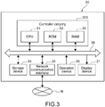
- Fig. 3 shows a hardware configuration of a device management apparatus.
- the device management apparatus 30 includes the CPU 31, the ROM 32, the RAM 33, the storage device 34, which is a large-volume nonvolatile memory such as an HDD or an SSD, the network communication interface 35, the operation device 36, and the display device 37, and the bus 38 connecting them to each other.
- the CPU 31 the ROM 32, the RAM 33, the storage device 34, which is a large-volume nonvolatile memory such as an HDD or an SSD, the network communication interface 35, the operation device 36, and the display device 37, and the bus 38 connecting them to each other.
- the controller circuitry 300 includes the CPU 31, the ROM 32, and the RAM 33.
- the CPU 31 loads information processing programs stored in the ROM 32 in the RAM 33 and executes the information processing programs.
- the ROM 32 stores programs executable by the CPU 31, data, and the like nonvolatile.
- the ROM 32 is an example of a non-transitory computer readable recording medium.
- Fig. 4 shows an operational flow of the device management system.
- Fig. 4 also shows a functional configuration of the device management system 1.
- the image forming device 16 includes, as a maintainable component, the feed roller 161.
- the storage device 18 stores the cumulative number of fed sheets 181, the time-length-for-feeding threshold 182, and the production class information 183.
- the feed roller 161 has one of various "production classes".
- the production class information 183 is information for specifying the production class.
- the "production class” is for example, a production lot of the feed roller 161. In this case, the production class information 183 is a lot number.
- the cumulative number of fed sheets 181 is a counted value of the number of sheets fed into the image forming device 16.
- the cumulative number of fed sheets 181 is about a number of use of the image forming apparatus 10 by users. In the present embodiment, every time the feed roller 161 is replaced, the cumulative number of fed sheets 181 at the time of replacement is also stored in the storage device 18.
- the time-length-for-feeding threshold 182 is a threshold, where a "time-length-for-feeding" is treated as a normal operation as a design specification.
- the "time-length-for-feeding" is a time length that a sheet travels from a feeder (not shown) to the main part of the image forming device 16 by using the feed roller 161.
- a manager of the device management system 1 sets a certain value (or range) as the time-length-for-feeding threshold 182.
- Step S1 Initial setting
- the controller circuitry 11 stores the time-length-for-feeding threshold 182 in the storage device 18 depending on an operational input of a user input from the operation device 17.
- the controller circuitry 300 stores the number of fed sheets in early failure period 341 in the storage device 34, which is specified by the manager of the device management system 1.
- the image forming apparatus 10 may store the time-length-for-feeding threshold 182 based on a command sent from the device management apparatus 30 to the image forming apparatus 10.
- Step S2 Normal operation
- the controller circuitry 11 Every time a feed operation using the feed roller 161 is executed in response to an operation input by a user, the controller circuitry 11 detects the "time-length-for-feeding", which is a time length required for the feed operation. Further, the controller circuitry 11 detects whether or not a failure of the feed roller 161 occurs. If a failure of the feed roller 161 is detected, the controller circuitry 11 notifies the device management apparatus 30 of that fact. Also, if the time-length-for-feeding exceeds the time-length-for-feeding threshold 182, the controller circuitry 11 notifies the device management apparatus 30 of that fact.
- Step S3 Notification to device management apparatus
- the controller circuitry 11 sends a signal, which notifies the device management apparatus 30 of that fact. Also, if the time-length-for-feeding exceeds the time-length-for-feeding threshold 182, the controller circuitry 11 sends a signal, which notifies the device management apparatus 30 of that fact. At those times, the controller circuitry 11 also notifies the device management apparatus 30 of the cumulative number of fed sheets 181 (the cumulative number of fed sheets 181 from the last replacement to the failure) at that time and the production class information 183 of the feed roller 161.
- Step S4 Analysis of failure density
- the controller circuitry 300 of the device management apparatus 30 receives the failure notification, and stores the number of fed sheets 342 at the time of the failure occurrence in the storage device 34.
- the controller circuitry 300 calculates "the failure density depending on the number of fed sheets 343" for each production class specified based on the production class information 183 based on the number of fed sheets 342 at the failure occurrence received from the multiple image forming apparatuses 10.
- ⁇ is a Weibull factor (shape parameter)
- ⁇ is a scale parameter
- x is the number of fed sheets.
- x is the cumulative number of fed sheets 181 at the time of a failure of the feed roller 161, which is a maintainable component, from the last replacement to the failure.
- Step S5 Maintenance determination
- the device management apparatus 30 receives a notification, which indicates that the time-length-for-feeding exceeds the time-length-for-feeding threshold 182, from the image forming apparatus 10.
- the device management apparatus 30 uses the failure density function of the production lot of the feed roller 161, which is used in the image forming apparatus 10.
- the device management apparatus 30 calculates the occurrence probability of early failures until it reaches the number of fed sheets in early failure period 341.
- the number of fed sheets in early failure period 341 is, as described above, a certain number of fed sheets and is a preset number of fed sheets, which is treated as an early failure if the feed roller 161 has a failure.
- the number of fed sheets in early failure period 341 is the maximum value of the number of fed sheets treated as an early failure period.
- the controller circuitry 300 calculates the early failure occurrence probability (in other words, cumulative value of failure density 343) until the number of fed sheets in early failure period is attained (the cumulative number of sheets is reset after replacement) based on the failure density function of the production lot of a replaceable component.
- the controller circuitry 300 compares the both, and determines that the component should be replaced where the occurrence probability after replacement is lower than the other. Where the early failure occurrence probability after replacement is not lower than the other, the controller circuitry 300 determines that the component should be maintained without replacement.
- the time-length-for-feeding exceeds the time-length-for-feeding threshold 182, i.e., a so-called sign of failure, is detected.
- the image forming apparatus 10 notifies the device management apparatus 30 of that fact (Step S2).
- the device management apparatus may determine the maintenance before a failure actually occurs (Step S5), and it is possible to prevent occurrence of an early failure and occurrence of downtime resulting from that in advance.
- Fig. 5 shows a maintenance determination process based on a failure density and the number of fed sheets.
- the number of fed sheets in early failure period 341 is "1000 sheets”.
- the failure density of the feed roller 161 of the first production class changes depending on the number of fed sheets.
- the failure density of the feed roller 161 of the first production class also changes depending on the number of fed sheets. Note that, typically, the failure density for a while after a maintainable component is replaced (before the early failure period passes) is higher than the failure density after the early failure period passes. After the early failure period passes, the failure density becomes stable.
- the first production class is the "early lot”
- the second production class is the "later lot”.
- the time-length-for-feeding exceeds the time-length-for-feeding threshold 182 at the time of feeding the 200th sheet (Q).
- the cumulative value area below curve of the failure density of the early lot is obtained.
- the cumulative value is the early failure occurrence probability where the early lot component is used without being replaced.
- the cumulative value of the failure density of the later lot is obtained.
- the cumulative value is the early failure occurrence probability where the early lot component is replaced by the later lot component.
- the device management apparatus 30 compares the cumulative value of the failure density in the span Q to P1 against the cumulative value of the failure density in the span Q to P2, and determines maintenance. In the example of Fig. 5 , the latter is smaller. So the device management apparatus 30 determines that the early lot component should be replaced by the later lot component.
- the "maintainable component” is a "feed roller", for example.
- the “maintainable component” may be a “conveyer roller”, a “fuser roller”, or an “intermediate transfer belt”.
- the time that takes for a conveyer operation or the time that takes for a fuser operation of fusing a formed image on a sheet may be a "parameter”.
- a "wear-out failure" occurs as a result of wear-out of a maintainable component as a result of printing.
- replacement timing typically, a service person visits a customer site regularly, and then determines whether or not it is necessary to replace a maintainable component.
- a service person does not want to bring heavy spares for all the maintainable components for regular visits. So the service person has to select necessary maintainable components for replacement based on the service person's experiences and the like.
Abstract
Description
- The present disclosure relates to a device management system including multiple image forming apparatuses.
- Further, the present disclosure relates to a device management apparatus that communicates with the multiple image forming apparatuses.
- An image forming apparatus has a component which should be replaced according to its lifetime. Such a component will be hereinafter referred to as a "maintainable component".
- It is desirable that a maintainable component should be replaced at appropriate timing.
- According to the present embodiment, there is provided a device management system (1), including:
- multiple image forming apparatuses (10); and
- a device management apparatus (30) communicably connected to the multiple image forming apparatuses (10) via a network,
- the image forming apparatus (10) including
- a maintainable component (161) being a replaceable component,
- a storage device configured to store a threshold of a parameter, the parameter being obtained after an operation, where an operation about the maintainable component (161) is treated as a normal operation, and
- a communication device configured to, where the parameter exceeds the threshold after an operation and where the maintainable component (161) has a failure, send a cumulative number of fed sheets at that time to the device management apparatus (30),
- the device management apparatus (30) including
- a storage device configured to store a number of fed sheets in an early failure period, the number of fed sheets in the early failure period being a certain number of fed sheets and being a preset number of fed sheets, which is treated as an early failure where the maintainable component (161) has a failure, and
- a controller circuitry configured to
- calculate a failure density depending on a number of fed sheets based on a number of fed sheets at a time when a failure occurred in the maintainable component (161), which is received from the multiple image forming apparatuses (10), and
- output information about replacement of the maintainable component (161) based on the failure density to the number of fed sheets in the early failure period from a number of fed sheets at a time when the parameter exceeds the threshold after an operation, which is received from one image forming apparatus (10).
- According to the present embodiment, there is provided a device management apparatus (30), including:
- a communication device configured to communicably connected to an image forming apparatus (10) via a network,
- the image forming apparatus (10) including
- a maintainable component (161) being a replaceable component,
- a storage device configured to store a threshold of a parameter, the parameter being obtained after an operation, where an operation about the maintainable component (161) is treated as a normal operation, and
- a communication device configured to, where the parameter exceeds the threshold after an operation and where the maintainable component (161) has a failure, send a cumulative number of fed sheets at that time to the device management apparatus (30);
- a storage device configured to store a number of fed sheets in an early failure period, the number of fed sheets in the early failure period being a certain number of fed sheets and being a preset number of fed sheets, which is treated as an early failure where the maintainable component (161) has a failure; and
- a controller circuitry configured to
- calculate a failure density depending on a number of fed sheets based on a number of fed sheets at a time when a failure occurred in the maintainable component (161), which is received from the multiple image forming apparatuses (10), and
- output information about replacement of the maintainable component (161) based on the failure density to the number of fed sheets in the early failure period from a number of fed sheets at a time when the parameter exceeds the threshold after an operation, which is received from one image forming apparatus (10).
- These and other objects, features and advantages of the present disclosure will become more apparent in light of the following detailed description of best mode embodiments thereof, as illustrated in the accompanying drawings.
-
-
Fig. 1 shows a configuration of a device management system according to an embodiment of the present disclosure; -
Fig. 2 shows a hardware configuration of an image forming apparatus; -
Fig. 3 shows a hardware configuration of a device management apparatus; -
Fig. 4 shows an operational flow of the device management system; and -
Fig. 5 shows a maintenance determination process based on a failure density and the number of fed sheets. - In the following embodiment, a "maintainable component" is a "feed roller", an "operation about the maintainable component" is a "feeding (operation)", and a "parameter obtained after an operation" is a "time-length-for-feeding", which are merely examples.
-
Fig. 1 shows a configuration of a device management system according to an embodiment of the present disclosure. - The
device management system 1 is a computer system in which the multipleimage forming apparatuses 10 communicate with thedevice management apparatus 30 via the network N. The network N is, for example, the Internet. Theimage forming apparatus 10 is, for example, an MFP (Multifunctional Peripheral). Thedevice management apparatus 30 is a typical computer and functions as a server apparatus. -
Fig. 2 shows a hardware configuration of an image forming apparatus. - A hardware configuration of the
image forming apparatus 10 will be described. Theimage forming apparatus 10 includes thecontroller circuitry 11. Thecontroller circuitry 11 includes the CPU (Central Processing Unit) 11a, the RAM (Random Access Memory) 11b, the ROM (Read Only Memory) 11c, dedicated hardware circuitries, and the like and performs overall operational control of theimage forming apparatus 10. TheCPU 11a loads information processing programs stored in theROM 11c in theRAM 11b and executes the information processing programs. TheROM 11c is a nonvolatile memory that stores programs executable by theCPU 11a, data, and the like. TheROM 11c is an example of a non-transitory computer readable recording medium. - The
controller circuitry 11 is connected to theimage scanner 12, the image processor 14 (including GPU (Graphics Processing Unit)), theimage memory 15, the image forming device 16 (printer), theoperation device 17 including thedisplay device 17a (touch panel), the large volumenonvolatile storage device 18 such as an HDD (Hard Disk Drive) or an SSD (Step Solid State Drive), thefacsimile communication device 19, thenetwork communication interface 13, and the like. Thecontroller circuitry 11 performs operational control of the respective devices connected thereto and sends/receives signals and data to/from those devices. The operation device 17 (touch panel) is one mode of an input device. A sound input device including a microphone may be provided as an input device. -
Fig. 3 shows a hardware configuration of a device management apparatus. - The
device management apparatus 30 includes theCPU 31, theROM 32, theRAM 33, thestorage device 34, which is a large-volume nonvolatile memory such as an HDD or an SSD, thenetwork communication interface 35, theoperation device 36, and thedisplay device 37, and thebus 38 connecting them to each other. - The
controller circuitry 300 includes theCPU 31, theROM 32, and theRAM 33. TheCPU 31 loads information processing programs stored in theROM 32 in theRAM 33 and executes the information processing programs. TheROM 32 stores programs executable by theCPU 31, data, and the like nonvolatile. TheROM 32 is an example of a non-transitory computer readable recording medium. -
Fig. 4 shows an operational flow of the device management system. -
Fig. 4 also shows a functional configuration of thedevice management system 1. In theimage forming apparatus 10, theimage forming device 16 includes, as a maintainable component, thefeed roller 161. In theimage forming apparatus 10, thestorage device 18 stores the cumulative number of fedsheets 181, the time-length-for-feeding threshold 182, and theproduction class information 183. - The
feed roller 161 has one of various "production classes". Theproduction class information 183 is information for specifying the production class. The "production class" is for example, a production lot of thefeed roller 161. In this case, theproduction class information 183 is a lot number. - The cumulative number of fed
sheets 181 is a counted value of the number of sheets fed into theimage forming device 16. The cumulative number of fedsheets 181 is about a number of use of theimage forming apparatus 10 by users. In the present embodiment, every time thefeed roller 161 is replaced, the cumulative number of fedsheets 181 at the time of replacement is also stored in thestorage device 18. - The time-length-for-
feeding threshold 182 is a threshold, where a "time-length-for-feeding" is treated as a normal operation as a design specification. The "time-length-for-feeding" is a time length that a sheet travels from a feeder (not shown) to the main part of theimage forming device 16 by using thefeed roller 161. A manager of thedevice management system 1 sets a certain value (or range) as the time-length-for-feeding threshold 182. - (Step S1: Initial setting) In the
image forming apparatus 10, thecontroller circuitry 11 stores the time-length-for-feeding threshold 182 in thestorage device 18 depending on an operational input of a user input from theoperation device 17. Meanwhile, in thedevice management apparatus 30, thecontroller circuitry 300 stores the number of fed sheets inearly failure period 341 in thestorage device 34, which is specified by the manager of thedevice management system 1. Note that theimage forming apparatus 10 may store the time-length-for-feeding threshold 182 based on a command sent from thedevice management apparatus 30 to theimage forming apparatus 10. - (Step S2: Normal operation) Every time a feed operation using the
feed roller 161 is executed in response to an operation input by a user, thecontroller circuitry 11 detects the "time-length-for-feeding", which is a time length required for the feed operation. Further, thecontroller circuitry 11 detects whether or not a failure of thefeed roller 161 occurs. If a failure of thefeed roller 161 is detected, thecontroller circuitry 11 notifies thedevice management apparatus 30 of that fact. Also, if the time-length-for-feeding exceeds the time-length-for-feeding threshold 182, thecontroller circuitry 11 notifies thedevice management apparatus 30 of that fact. - (Step S3: Notification to device management apparatus) If the
feed roller 161 has a failure, thecontroller circuitry 11 sends a signal, which notifies thedevice management apparatus 30 of that fact. Also, if the time-length-for-feeding exceeds the time-length-for-feeding threshold 182, thecontroller circuitry 11 sends a signal, which notifies thedevice management apparatus 30 of that fact. At those times, thecontroller circuitry 11 also notifies thedevice management apparatus 30 of the cumulative number of fed sheets 181 (the cumulative number of fedsheets 181 from the last replacement to the failure) at that time and theproduction class information 183 of thefeed roller 161. - (Step S4: Analysis of failure density) The
controller circuitry 300 of thedevice management apparatus 30 receives the failure notification, and stores the number of fedsheets 342 at the time of the failure occurrence in thestorage device 34. Thecontroller circuitry 300 calculates "the failure density depending on the number of fedsheets 343" for each production class specified based on theproduction class information 183 based on the number of fedsheets 342 at the failure occurrence received from the multipleimage forming apparatuses 10. "The failure density depending on the number of fedsheets 343" is represented by the following failure index density function based on the Weibull distribution.
- In the expression, α is a Weibull factor (shape parameter), β is a scale parameter, and x is the number of fed sheets. In other words, x is the cumulative number of fed
sheets 181 at the time of a failure of thefeed roller 161, which is a maintainable component, from the last replacement to the failure. - (Step S5: Maintenance determination) The
device management apparatus 30 receives a notification, which indicates that the time-length-for-feeding exceeds the time-length-for-feeding threshold 182, from theimage forming apparatus 10. In this case, thedevice management apparatus 30 uses the failure density function of the production lot of thefeed roller 161, which is used in theimage forming apparatus 10. Then thedevice management apparatus 30 calculates the occurrence probability of early failures until it reaches the number of fed sheets inearly failure period 341. In this case, the number of fed sheets inearly failure period 341 is, as described above, a certain number of fed sheets and is a preset number of fed sheets, which is treated as an early failure if thefeed roller 161 has a failure. In other words, the number of fed sheets inearly failure period 341 is the maximum value of the number of fed sheets treated as an early failure period. - Further, the
controller circuitry 300 calculates the early failure occurrence probability (in other words, cumulative value of failure density 343) until the number of fed sheets in early failure period is attained (the cumulative number of sheets is reset after replacement) based on the failure density function of the production lot of a replaceable component. Thecontroller circuitry 300 compares the both, and determines that the component should be replaced where the occurrence probability after replacement is lower than the other. Where the early failure occurrence probability after replacement is not lower than the other, thecontroller circuitry 300 determines that the component should be maintained without replacement. - According to the aforementioned operational flow, the time-length-for-feeding exceeds the time-length-for-
feeding threshold 182, i.e., a so-called sign of failure, is detected. At the time of detection, theimage forming apparatus 10 notifies thedevice management apparatus 30 of that fact (Step S2). As a result, the device management apparatus may determine the maintenance before a failure actually occurs (Step S5), and it is possible to prevent occurrence of an early failure and occurrence of downtime resulting from that in advance. -
Fig. 5 shows a maintenance determination process based on a failure density and the number of fed sheets. InFig. 5 , the number of fed sheets inearly failure period 341 is "1000 sheets". As shown inFig. 5 , for example, the failure density of thefeed roller 161 of the first production class changes depending on the number of fed sheets. As shown inFig. 5 , for example, the failure density of thefeed roller 161 of the first production class also changes depending on the number of fed sheets. Note that, typically, the failure density for a while after a maintainable component is replaced (before the early failure period passes) is higher than the failure density after the early failure period passes. After the early failure period passes, the failure density becomes stable. - Hereinafter, the first production class is the "early lot", and the second production class is the "later lot".
- In
Fig. 5 , the time-length-for-feeding exceeds the time-length-for-feeding threshold 182 at the time of feeding the 200th sheet (Q). In this case, in the span Q to P1 (in other words, span from start of use of early lot component to the number of fed sheets inearly failure period 341 "1000 sheets"), the cumulative value (area below curve) of the failure density of the early lot is obtained. The cumulative value is the early failure occurrence probability where the early lot component is used without being replaced. Meanwhile, in the span Q to P2 (in other words, where early lot component is replaced by later lot component at time (Q), span from start of use of later lot component to the number of fed sheets inearly failure period 341 "1000 sheets"), the cumulative value of the failure density of the later lot is obtained. The cumulative value is the early failure occurrence probability where the early lot component is replaced by the later lot component. - The
device management apparatus 30 compares the cumulative value of the failure density in the span Q to P1 against the cumulative value of the failure density in the span Q to P2, and determines maintenance. In the example ofFig. 5 , the latter is smaller. So thedevice management apparatus 30 determines that the early lot component should be replaced by the later lot component. - In the present embodiment, the "maintainable component" is a "feed roller", for example. Alternatively, for example, the "maintainable component" may be a "conveyer roller", a "fuser roller", or an "intermediate transfer belt". Where each of them is a maintainable component, for example, the time that takes for a conveyer operation or the time that takes for a fuser operation of fusing a formed image on a sheet may be a "parameter".
- A "wear-out failure" occurs as a result of wear-out of a maintainable component as a result of printing. With regard to replacement timing, typically, a service person visits a customer site regularly, and then determines whether or not it is necessary to replace a maintainable component. A service person does not want to bring heavy spares for all the maintainable components for regular visits. So the service person has to select necessary maintainable components for replacement based on the service person's experiences and the like.
- (1) According to the present embodiment, one image forming apparatus obtains a parameter, the parameter being obtained after an operation, where an operation about the maintainable component is treated as a normal operation. Where the parameter exceeds the threshold, the image forming apparatus sends a cumulative number of fed sheets at that time to a device management apparatus. Meanwhile, the device management apparatus receives a cumulative number of fed sheets at a time when a failure occurred in the maintainable component from the image forming apparatus that has the failure. Based on that, the device management apparatus calculates a failure density depending on a number of fed sheets. The device management apparatus outputs information about replacement of the maintainable component of the one image forming apparatus based on the failure density to the predetermined number of fed sheets in the early failure period from a number of fed sheets at a time when the parameter exceeds the threshold. As a result, according to the present embodiment, information about replacement of a maintainable component may be output appropriately based on an early failure occurrence probability.
- (2) According to the present embodiment, the device management apparatus calculates the failure density for each production class (production time, lot, etc.) of the maintainable component. As a result, according to the present embodiment, an early failure occurrence probability, which is different depending on difference of lots of maintainable components, may be calculated. So information about replacement of a maintainable component may be output more appropriately.
- (3) According to the present embodiment, the device management apparatus outputs information about replacement of the maintainable component further based on the failure density calculated for the maintainable component of a second production class, the second production class being different from a production class (first production class) of the maintainable component about an operation, where the parameter exceeds the threshold. As a result, according to the present embodiment, production classes of maintainable components are compared against one another. So information about replacement of a maintainable component may be output more appropriately.
- It should be understood by those skilled in the art that various modifications, combinations, sub-combinations and alterations may occur depending on design requirements and other factors insofar as they are within the scope of the appended claims or the equivalents thereof.
Claims (4)
- A device management system (1), comprising:multiple image forming apparatuses (10); anda device management apparatus (30) communicably connected to the multiple image forming apparatuses (10) via a network,the image forming apparatus (10) includinga maintainable component (161) being a replaceable component,a storage device configured to store a threshold of a parameter, the parameter being obtained after an operation, where an operation about the maintainable component (161) is treated as a normal operation, anda communication device configured to, where the parameter exceeds the threshold after an operation and where the maintainable component (161) has a failure, send a cumulative number of fed sheets at that time to the device management apparatus (30),the device management apparatus (30) includinga storage device configured to store a number of fed sheets in an early failure period, the number of fed sheets in the early failure period being a certain number of fed sheets and being a preset number of fed sheets, which is treated as an early failure where the maintainable component (161) has a failure, anda controller circuitry configured tocalculate a failure density depending on a number of fed sheets based on a number of fed sheets at a time when a failure occurred in the maintainable component (161), which is received from the multiple image forming apparatuses (10), andoutput information about replacement of the maintainable component (161) based on the failure density to the number of fed sheets in the early failure period from a number of fed sheets at a time when the parameter exceeds the threshold after an operation, which is received from one image forming apparatus (10).
- The device management system (1) according to claim 1, wherein
the controller circuitry of the device management apparatus (30) is configured to calculate the failure density for each production class of the maintainable component (161). - The device management system (1) according to claim 2, wherein
the controller circuitry of the device management apparatus (30) is configured to output information about replacement of the maintainable component (161) further based on the failure density calculated for the maintainable component (161) of a second production class, the second production class being different from a first production class of the maintainable component (161) about an operation, where the parameter exceeds the threshold. - A device management apparatus (30), comprising:a communication device configured to communicably connected to an image forming apparatus (10) via a network,the image forming apparatus (10) includinga maintainable component (161) being a replaceable component,a storage device configured to store a threshold of a parameter, the parameter being obtained after an operation, where an operation about the maintainable component (161) is treated as a normal operation, anda communication device configured to, where the parameter exceeds the threshold after an operation and where the maintainable component (161) has a failure, send a cumulative number of fed sheets at that time to the device management apparatus (30);a storage device configured to store a number of fed sheets in an early failure period, the number of fed sheets in the early failure period being a certain number of fed sheets and being a preset number of fed sheets, which is treated as an early failure where the maintainable component (161) has a failure; anda controller circuitry configured tocalculate a failure density depending on a number of fed sheets based on a number of fed sheets at a time when a failure occurred in the maintainable component (161), which is received from the multiple image forming apparatuses (10), andoutput information about replacement of the maintainable component (161) based on the failure density to the number of fed sheets in the early failure period from a number of fed sheets at a time when the parameter exceeds the threshold after an operation, which is received from one image forming apparatus (10).
Applications Claiming Priority (1)
| Application Number | Priority Date | Filing Date | Title |
|---|---|---|---|
| JP2019119953A JP2021005306A (en) | 2019-06-27 | 2019-06-27 | Apparatus management system and apparatus management device |
Publications (1)
| Publication Number | Publication Date |
|---|---|
| EP3757705A1 true EP3757705A1 (en) | 2020-12-30 |
Family
ID=71120091
Family Applications (1)
| Application Number | Title | Priority Date | Filing Date |
|---|---|---|---|
| EP20181395.3A Pending EP3757705A1 (en) | 2019-06-27 | 2020-06-22 | Device management system and device management apparatus |
Country Status (4)
| Country | Link |
|---|---|
| US (1) | US11036570B2 (en) |
| EP (1) | EP3757705A1 (en) |
| JP (1) | JP2021005306A (en) |
| CN (1) | CN112148234B (en) |
Families Citing this family (1)
| Publication number | Priority date | Publication date | Assignee | Title |
|---|---|---|---|---|
| JP2021005306A (en) * | 2019-06-27 | 2021-01-14 | 京セラドキュメントソリューションズ株式会社 | Apparatus management system and apparatus management device |
Citations (2)
| Publication number | Priority date | Publication date | Assignee | Title |
|---|---|---|---|---|
| EP1126391A2 (en) * | 2000-02-14 | 2001-08-22 | Canon Kabushiki Kaisha | Expendable management method and system |
| JP2019018990A (en) * | 2017-07-21 | 2019-02-07 | 京セラドキュメントソリューションズ株式会社 | Image forming system |
Family Cites Families (29)
| Publication number | Priority date | Publication date | Assignee | Title |
|---|---|---|---|---|
| US5303005A (en) * | 1990-01-31 | 1994-04-12 | Minolta Camera Kabushiki Kaisha | Image forming apparatus with improved maintenance control |
| JP2534387B2 (en) * | 1990-09-21 | 1996-09-11 | 三田工業株式会社 | Self-diagnosis system for image forming apparatus |
| JPH1034122A (en) * | 1996-07-25 | 1998-02-10 | Fuji Xerox Co Ltd | Part selection method in commodity recycle system |
| KR100419215B1 (en) * | 2001-05-16 | 2004-02-19 | 삼성전자주식회사 | Inkjet multi function device capable of repairing malfunction of a nozzle, and a method for maintaining the same |
| KR100571782B1 (en) * | 2004-01-16 | 2006-04-18 | 삼성전자주식회사 | An apparatus having Self error Diagnostics for printing system and a method thereof |
| JP2005309077A (en) * | 2004-04-21 | 2005-11-04 | Fuji Xerox Co Ltd | Fault diagnostic method, fault diagnostic system, transporting device, and image forming apparatus, and program and storage medium |
| US7817293B2 (en) * | 2005-01-07 | 2010-10-19 | Infoprint Solutions Company, Llc | Trace and debug tool for high speed printer systems |
| EP1688842B1 (en) * | 2005-01-26 | 2008-02-20 | Océ-Technologies B.V. | Automated performance analysis and failure remediation |
| JP4362782B2 (en) * | 2005-06-30 | 2009-11-11 | ブラザー工業株式会社 | Image printing apparatus and error information output program for image printing apparatus |
| WO2007127905A2 (en) * | 2006-04-27 | 2007-11-08 | Fujifilm Graphic Systems U.S.A., Inc | System and method for remote monitoring of print systems |
| JP2007323148A (en) * | 2006-05-30 | 2007-12-13 | Hitachi Ltd | Management support device, program and management support method |
| JP4710720B2 (en) * | 2006-06-02 | 2011-06-29 | 富士ゼロックス株式会社 | Failure prevention diagnosis support system and failure prevention diagnosis support method |
| US7467841B2 (en) * | 2006-09-07 | 2008-12-23 | Kabushiki Kaisha Toshiba | Maintenance scheduling system, maintenance scheduling method and image forming apparatus |
| US8607102B2 (en) * | 2006-09-15 | 2013-12-10 | Palo Alto Research Center Incorporated | Fault management for a printing system |
| JP5159110B2 (en) * | 2007-01-05 | 2013-03-06 | 株式会社東芝 | System maintenance method, maintenance device and program |
| US8099310B2 (en) * | 2008-02-19 | 2012-01-17 | Kabushiki Kaisha Toshiba | Maintenance scheduling system, maintenance scheduling method, and image forming apparatus |
| JP2011011427A (en) * | 2009-07-01 | 2011-01-20 | Oki Data Corp | Electronic device and electronic system |
| US20110216359A1 (en) * | 2010-03-03 | 2011-09-08 | Kabushiki Kaisha Toshiba | Maintenance scheduling system and maintenance schedule creating method |
| US8819498B2 (en) * | 2011-09-09 | 2014-08-26 | Xerox Corporation | Fault-based unit replacement |
| JP6536213B2 (en) * | 2015-06-23 | 2019-07-03 | 株式会社リコー | System and service determination method |
| JP6398959B2 (en) * | 2015-12-03 | 2018-10-03 | 京セラドキュメントソリューションズ株式会社 | Image forming apparatus |
| JP2018054742A (en) * | 2016-09-27 | 2018-04-05 | キヤノン株式会社 | Image processing device, image processing device control method and program |
| JP6849385B2 (en) * | 2016-10-18 | 2021-03-24 | キヤノン株式会社 | Image processing equipment, information processing methods and programs |
| JP6849498B2 (en) * | 2017-03-17 | 2021-03-24 | キヤノン株式会社 | Image forming device and feeding device |
| JP6977305B2 (en) * | 2017-04-28 | 2021-12-08 | コニカミノルタ株式会社 | Printing equipment, maintenance control program and maintenance control method |
| JP7040270B2 (en) * | 2017-05-08 | 2022-03-23 | 富士通株式会社 | Warehouse management equipment, warehouse management methods, and programs |
| US20190272209A1 (en) * | 2018-03-05 | 2019-09-05 | Kabushiki Kaisha Toshiba | System and method of resolution prediction for multifunction peripheral failures |
| US10423865B1 (en) * | 2018-03-06 | 2019-09-24 | Kabushiki Kaisha Toshiba | System and method of prediction of paper jams on multifunction peripherals |
| JP2021005306A (en) * | 2019-06-27 | 2021-01-14 | 京セラドキュメントソリューションズ株式会社 | Apparatus management system and apparatus management device |
-
2019
- 2019-06-27 JP JP2019119953A patent/JP2021005306A/en active Pending
-
2020
- 2020-06-22 EP EP20181395.3A patent/EP3757705A1/en active Pending
- 2020-06-23 CN CN202010579189.XA patent/CN112148234B/en active Active
- 2020-06-23 US US16/908,983 patent/US11036570B2/en active Active
Patent Citations (2)
| Publication number | Priority date | Publication date | Assignee | Title |
|---|---|---|---|---|
| EP1126391A2 (en) * | 2000-02-14 | 2001-08-22 | Canon Kabushiki Kaisha | Expendable management method and system |
| JP2019018990A (en) * | 2017-07-21 | 2019-02-07 | 京セラドキュメントソリューションズ株式会社 | Image forming system |
Also Published As
| Publication number | Publication date |
|---|---|
| US11036570B2 (en) | 2021-06-15 |
| CN112148234A (en) | 2020-12-29 |
| US20200409777A1 (en) | 2020-12-31 |
| CN112148234B (en) | 2024-04-19 |
| JP2021005306A (en) | 2021-01-14 |
Similar Documents
| Publication | Publication Date | Title |
|---|---|---|
| MX2012010165A (en) | Fault-based unit replacement. | |
| US10060834B2 (en) | Failure prediction apparatus and failure prediction system | |
| US8514425B2 (en) | Image-forming system, criterion-setting apparatus, and storage medium | |
| JP6318674B2 (en) | Failure prediction system, failure prediction device, and program | |
| US11436457B2 (en) | Image forming apparatus and control method for image forming apparatus | |
| US20090132589A1 (en) | System and method for threshold-based notification of document processing device status | |
| US20200041944A1 (en) | Image forming apparatus, method for controlling the same, and image forming system | |
| JP2018017894A (en) | Image formation device | |
| EP3757705A1 (en) | Device management system and device management apparatus | |
| US9001350B2 (en) | Image processing apparatus, control method, and storage medium in which the load can be suppressed during a maintenance event | |
| CN103207547A (en) | Image forming apparatus and control method thereof | |
| US9323484B2 (en) | Print instruction apparatus, printer, printing system, print instruction method, and non-transitory computer readable medium | |
| US20200192343A1 (en) | Apparatus, control method of apparatus and control method of management apparatus | |
| US8977142B2 (en) | Malfunction inferring apparatus, malfunction inferring method, and non-transitory computer readable medium | |
| US20150077785A1 (en) | Image forming apparatus having secure printing function, control method therefor, and storage medium | |
| US11200010B2 (en) | System and method for increasing page yield of a replaceable toner cartridge | |
| US20070160378A1 (en) | Image forming apparatus, charging process apparatus, and image forming system | |
| US9843695B2 (en) | Information processing system for acquiring the state of information processing apparatuses and determining whether to restrict a requested process | |
| US20200265277A1 (en) | Information processing apparatus, non-transitory computer readable recording medium that records information processing program, and information processing method | |
| US11301182B2 (en) | Control apparatus, image forming apparatus, information processing apparatus, control method, and storage medium for predicting possibility of malfunction | |
| US9791815B2 (en) | Printing apparatus, method of controlling the same, and computer-readable storage medium | |
| US10748046B2 (en) | Consumable-component management apparatus, control method, and storage medium storing program | |
| US9609146B2 (en) | Management system, management device and image forming apparatus | |
| EP2843541B1 (en) | Electronic apparatus | |
| US20160085611A1 (en) | Information processing apparatus, management system, and non-transitory computer readable medium |
Legal Events
| Date | Code | Title | Description |
|---|---|---|---|
| PUAI | Public reference made under article 153(3) epc to a published international application that has entered the european phase |
Free format text: ORIGINAL CODE: 0009012 |
|
| STAA | Information on the status of an ep patent application or granted ep patent |
Free format text: STATUS: THE APPLICATION HAS BEEN PUBLISHED |
|
| AK | Designated contracting states |
Kind code of ref document: A1 Designated state(s): AL AT BE BG CH CY CZ DE DK EE ES FI FR GB GR HR HU IE IS IT LI LT LU LV MC MK MT NL NO PL PT RO RS SE SI SK SM TR |
|
| AX | Request for extension of the european patent |
Extension state: BA ME |
|
| STAA | Information on the status of an ep patent application or granted ep patent |
Free format text: STATUS: REQUEST FOR EXAMINATION WAS MADE |
|
| 17P | Request for examination filed |
Effective date: 20210629 |
|
| RBV | Designated contracting states (corrected) |
Designated state(s): AL AT BE BG CH CY CZ DE DK EE ES FI FR GB GR HR HU IE IS IT LI LT LU LV MC MK MT NL NO PL PT RO RS SE SI SK SM TR |
|
| STAA | Information on the status of an ep patent application or granted ep patent |
Free format text: STATUS: EXAMINATION IS IN PROGRESS |
|
| 17Q | First examination report despatched |
Effective date: 20221031 |
|
| P01 | Opt-out of the competence of the unified patent court (upc) registered |
Effective date: 20230420 |