EP3757693B1 - System und verfahren zum betrieb einer automatisierten maschine, automatisierte maschine und computerprogrammprodukt - Google Patents
System und verfahren zum betrieb einer automatisierten maschine, automatisierte maschine und computerprogrammprodukt Download PDFInfo
- Publication number
- EP3757693B1 EP3757693B1 EP19183402.7A EP19183402A EP3757693B1 EP 3757693 B1 EP3757693 B1 EP 3757693B1 EP 19183402 A EP19183402 A EP 19183402A EP 3757693 B1 EP3757693 B1 EP 3757693B1
- Authority
- EP
- European Patent Office
- Prior art keywords
- safety
- description data
- technical
- sensor
- sensor device
- Prior art date
- Legal status (The legal status is an assumption and is not a legal conclusion. Google has not performed a legal analysis and makes no representation as to the accuracy of the status listed.)
- Active
Links
Images




Classifications
-
- G—PHYSICS
- G05—CONTROLLING; REGULATING
- G05B—CONTROL OR REGULATING SYSTEMS IN GENERAL; FUNCTIONAL ELEMENTS OF SUCH SYSTEMS; MONITORING OR TESTING ARRANGEMENTS FOR SUCH SYSTEMS OR ELEMENTS
- G05B23/00—Testing or monitoring of control systems or parts thereof
- G05B23/02—Electric testing or monitoring
- G05B23/0205—Electric testing or monitoring by means of a monitoring system capable of detecting and responding to faults
- G05B23/0208—Electric testing or monitoring by means of a monitoring system capable of detecting and responding to faults characterized by the configuration of the monitoring system
- G05B23/0213—Modular or universal configuration of the monitoring system, e.g. monitoring system having modules that may be combined to build monitoring program; monitoring system that can be applied to legacy systems; adaptable monitoring system; using different communication protocols
-
- G—PHYSICS
- G05—CONTROLLING; REGULATING
- G05B—CONTROL OR REGULATING SYSTEMS IN GENERAL; FUNCTIONAL ELEMENTS OF SUCH SYSTEMS; MONITORING OR TESTING ARRANGEMENTS FOR SUCH SYSTEMS OR ELEMENTS
- G05B19/00—Program-control systems
- G05B19/02—Program-control systems electric
- G05B19/418—Total factory control, i.e. centrally controlling a plurality of machines, e.g. direct or distributed numerical control [DNC], flexible manufacturing systems [FMS], integrated manufacturing systems [IMS] or computer integrated manufacturing [CIM]
- G05B19/41835—Total factory control, i.e. centrally controlling a plurality of machines, e.g. direct or distributed numerical control [DNC], flexible manufacturing systems [FMS], integrated manufacturing systems [IMS] or computer integrated manufacturing [CIM] characterised by program execution
-
- G—PHYSICS
- G05—CONTROLLING; REGULATING
- G05B—CONTROL OR REGULATING SYSTEMS IN GENERAL; FUNCTIONAL ELEMENTS OF SUCH SYSTEMS; MONITORING OR TESTING ARRANGEMENTS FOR SUCH SYSTEMS OR ELEMENTS
- G05B19/00—Program-control systems
- G05B19/02—Program-control systems electric
- G05B19/04—Program control other than numerical control, i.e. in sequence controllers or logic controllers
- G05B19/042—Program control other than numerical control, i.e. in sequence controllers or logic controllers using digital processors
- G05B19/0426—Programming the control sequence
-
- G—PHYSICS
- G05—CONTROLLING; REGULATING
- G05B—CONTROL OR REGULATING SYSTEMS IN GENERAL; FUNCTIONAL ELEMENTS OF SUCH SYSTEMS; MONITORING OR TESTING ARRANGEMENTS FOR SUCH SYSTEMS OR ELEMENTS
- G05B19/00—Program-control systems
- G05B19/02—Program-control systems electric
- G05B19/04—Program control other than numerical control, i.e. in sequence controllers or logic controllers
- G05B19/042—Program control other than numerical control, i.e. in sequence controllers or logic controllers using digital processors
- G05B19/0428—Safety, monitoring
-
- G—PHYSICS
- G05—CONTROLLING; REGULATING
- G05B—CONTROL OR REGULATING SYSTEMS IN GENERAL; FUNCTIONAL ELEMENTS OF SUCH SYSTEMS; MONITORING OR TESTING ARRANGEMENTS FOR SUCH SYSTEMS OR ELEMENTS
- G05B23/00—Testing or monitoring of control systems or parts thereof
- G05B23/02—Electric testing or monitoring
- G05B23/0205—Electric testing or monitoring by means of a monitoring system capable of detecting and responding to faults
- G05B23/0259—Electric testing or monitoring by means of a monitoring system capable of detecting and responding to faults characterized by the response to fault detection
- G05B23/0286—Modifications to the monitored process, e.g. stopping operation or adapting control
-
- G—PHYSICS
- G05—CONTROLLING; REGULATING
- G05B—CONTROL OR REGULATING SYSTEMS IN GENERAL; FUNCTIONAL ELEMENTS OF SUCH SYSTEMS; MONITORING OR TESTING ARRANGEMENTS FOR SUCH SYSTEMS OR ELEMENTS
- G05B2219/00—Program-control systems
- G05B2219/20—Pc systems
- G05B2219/24—Pc safety
- G05B2219/24024—Safety, surveillance
-
- G—PHYSICS
- G05—CONTROLLING; REGULATING
- G05B—CONTROL OR REGULATING SYSTEMS IN GENERAL; FUNCTIONAL ELEMENTS OF SUCH SYSTEMS; MONITORING OR TESTING ARRANGEMENTS FOR SUCH SYSTEMS OR ELEMENTS
- G05B2219/00—Program-control systems
- G05B2219/30—Nc systems
- G05B2219/31—From computer integrated manufacturing till monitoring
- G05B2219/31229—Supervisor, leader, workstation controller, automation, machine control
Definitions
- the present disclosure relates to systems, methods and computer-program products for operating automated machines, such as for operating factory automation systems, industrial networks, and the like. Further, automated machines, automation systems and networks of interacting devices are disclosed. In particular, safety aspects of automation systems including controlled interacting devices are considered.
- US 10,051,349 B2 discloses a system with plural sensor devices installed at a premises and a server computer coupled to a network and in communication with a gateway, which receives a risk profile for-a physical premises, collect sensor information from the plural sensor devices and receives data feeds relevant to a location of the physical premises.
- Learning models are executed to analyze the collected sensor information and data feeds to produce operational decisions based on the sensor information and data feeds and to predict changes to risk profiles.
- the system includes an engine for monitoring the sensor devices to recognize occurrences of events, and ask, through an interface to a human for additional information to confirm an occurrence of the events.
- an industrial asset control system wherein a threat-detection model creation computer receives a series of normal monitoring node values (representing a normal operation of the industrial asset control system) and generates a set of normal feature vectors.
- the threat detection model creation computer also receives a series of threatened monitoring node values (representing a threatened operation of the industrial asset control system) and generates a set of threatened feature vectors.
- a decision boundary for a threat detection model is calculated based on the set of normal feature vectors, the set of threatened feature vectors, and an initial algorithm parameter.
- a performance of the decision boundary is evaluated based on a performance metric, and the initial algorithm parameter is tuned based on a result of the evaluation, so that the decision boundary may be re-calculated.
- WO 2016/079211 A1 discloses an electromechanical drive system with at least one electromechanical drive unit to actuate a movable component.
- the electromechanical drive unit comprises a drive unit interface for receiving drive unit control signals, an electromechanical motor controlled by actuation signals to actuate the component, a safety module and a position sensor connected to the safety module via a first data connection.
- EP 2 317 412 A1 discloses a safety management system for equipment adapted to operate autonomously in a real-time environment, in which both a deterministic processor and a non-deterministic processor are provided for processing incoming alerts and generating control signals in response.
- a system for operating an automated machine comprises a plurality of interacting technical devices, wherein each technical device is implemented to perform an associated action, and each technical device has associated technical-device description data including parameters characterizing the respective technical device and at least one safety-sensor device implemented to detect an observable state of a space in/or around the automated machine and implemented to detect a safety issue in said space, a malfunction of the automated machine and/or the safety-sensor device.
- Each safety-sensor device has associated safety-sensor device description data characterizing the detection of the observable state of the space in and/or around the automated machine by the respective safety-sensor device.
- the system for operating comprises:
- a method for operating an automated machine comprising:
- the method for operating comprises the steps of:
- a computer program product including computer-readable instructions causing a computing system including one or more processing devices in response to executing the computer-readable instructions, to:
- the automated machine referred to may comprise:
- a control device comprising a plurality of processing devices, may autonomously assess as to whether the automated machine fulfills given safety rules that may be, for example, prescribed by certain regulations or standards.
- the control device may be implemented as an artificially intelligent unit capable of machine learning aspects, data mining, feature extraction or pattern recognition in an autonomous fashion.
- Interacting technical devices can be, for example, field devices in an automation network or production units that are controlled to execute the associated actions.
- Safety-sensor devices can be understood as monitoring the interacting technical devices and issuing safety warnings if, according to particular operational situations, a safety action needs to be taken. If, for example, personnel enter the particular observable state in a space, a safety-sensor device may issue a warning or an instruction to stop certain actions of the technical devices.
- the safety-sensor devices in particular, have a self-diagnosis function so that a malfunction of the safety-sensor device is noticed and may be remedied.
- description data for technical devices, sensor devices, safety-sensor devices or the automated machine include computer-readable information on the respective entity.
- safety-sensor device description data associated to a time-of-flight sensor used as a safety-sensor device may include a list of product features and parameters how the time-of-flight sensor can be used.
- the technical devices used in the automated machine can be specified by certain description data, in particular in a standardized computer-readable fashion.
- the description data can be used to physically implement the automated machine, and in particular safety functions within the automated machine.
- the database device storing a plurality of machine safety rules may comprise a data repository containing safety standard recommendations for machine configurations including technical devices and sensor devices and/or publicly available information documents.
- control device is implemented to:
- the automated machine can be described in terms of a specific profile, if certain technical devices, for example conveyor devices or specific robots, are deployed. Safety standards may then prescribe that safety sensors with specific properties should be used in such a system.
- control device is implemented to monitor the technical devices, the sensor devices and/or the safety-sensor devices in particular detect a change in the technical device, a sensor device, a safety-sensor device and/or an amendment in the technical-device description data or safety-sensor device description data.
- control device monitors and detects such amendments and can initiate actions to improve or reinstate the proper safety of the automated machine.
- a change may include a replacement. Wear, age, life cycle, operational times, operational mode, operating range of the technical device, a sensor device or a safety-sensor device.
- control device is implemented to, in response to a detected change or amendment, determine if the applicable safety rule is complied with. For example, the control device issues a warning message, if there is a breach of a safety rule due to a change or amendment in the automated machine.
- the system may further comprise a communications network implemented to communicatively couple the control device, technical devices, sensor devices and/or the safety-sensor devices.
- the communications network may be used to retrieve description data and transmit control data within the automated machine.
- a communications network can be based on an Ethernet standard or, for example, an IO-link standard at the time of the priority date of this application.
- the description data has a predetermined format.
- the predetermined format for a technical device or a sensor device or a safety-sensor device can be written as the device description in terms of the IO-link standard.
- the machine safety rules are received in a predetermined computer-readable format, extracted from safety standard documents in text form, scanned by means of a pattern or text recognition and/or a by natural language processing.
- Retrieving the machine safety rules and/or description data may include receiving a manual input by an operator.
- a control device may be implemented to automatically analyze safety standard documents and to generate the safety rules in a computer-readable predetermined format.
- the control device may extract the relevant content of a safety standard document as a function of the machine description data to obtain the relevant safety rules.
- the control device may identify based on the retrieved machine description, including the machine configuration times and connections of sensor and technical devices, the correct applicable standard documents.
- the control device may be implemented as a not specifically disclosed machine learning device, e.g. a neural network, which is specifically trained to extract safety rules from safety standard documents.
- the standard documents considered are safeguarding and risk assessment documents according to ISO 12100 at the time this application is filed.
- the referred safety standard documents are in particular ISO or IEC standards referring to automation networks.
- ISO standards 12100, 14120, 13854, 13857, 13855, 138491, 138492. 13856, 61496, 13851, 60204, 14119, 13850, IEC 61496 and the like are mentioned.
- determining if the retrieved data complies with the safety rules may includes a non-disclosed machine learning process, an expert system, monitoring and/or retrieving description data from an external environment of the automated machine and/or receiving manual input.
- system may further comprise a further database device implemented to provide expert data for resolving conflicts between safety-sensor device description data, technical-device description data, machine description data and/or safety rules.
- control device may further be implemented to:
- the amended safety-sensor device description data, amended technical-device description data and amended machine description data preferably comply with the retrieved safety rules.
- control device may continuously improve the safety of the automated machine.
- amended description data is generated and tested to improve the safety of the system.
- amended device description data can be generated to improve the efficiency of the automated machine.
- the automated machine further comprises a machine controller device implemented to generate control data for controlling the plurality of interacting technical devices and to receive sensor data and/or safety sensor data generated by the safety-sensor device and/or a sensor device.
- the control data is preferably generated as a function of the sensor data and the safety sensor data and according to a predetermined control algorithm.
- the control algorithm defines the function of certain aspects within the automated machine. For example, an algorithm may cause a robot to put items from a conveyor into a basket, wherein the basket, conveyor and robot may be considered a technical device each.
- control device for operating the system is implemented to monitor the control data, the sensor data and/or the safety sensor data during the operation of the automated machine.
- control data sensor data and safety sensor data is referred to as process data.
- Monitoring an acquiring process data allows the control device to analyze the operation of the automated machine and potentially amend the machine configuration data or safety rules in order to render the automated process more efficient or safer.
- the control device for operating the automated machine may issue messages or reports, that include amended description data based on the analysis of process data and/or changes in the description data.
- amended description data is checked and eventually used to implement physically an amended automated machine based on the amended description data.
- control device may be implemented to calculate a safety performance indicator (SPI) relating to the safety of the automated machine; and to amend the safety-sensor device description data, technical-device description data and/or the machine description data such that the safety performance indicator is improved.
- SPI safety performance indicator
- the safety performance indicator may be defined as to provide a safety level or measure for the safety of the automated machine.
- the safety performance indicator has a low value for a low safety level and a high value for a high safety level.
- At least one of the interacting technical devices is an actuator device, a robotic device, a transport device, a conveyor device and/or a sensor device.
- the at least one of the safety-sensor devices includes a light curtain device, a time-of-flight sensor device, a motion detector, a radar transmission and/or detection device, an ultrasonic transmission and/or detection device, a laser scanner device, a photoelectric device and/or a camera device.
- a light curtain device a time-of-flight sensor device
- a motion detector a radar transmission and/or detection device
- an ultrasonic transmission and/or detection device a laser scanner device
- a photoelectric device and/or a camera device One may contemplate of other safety-sensor devices used within an automated machine or network.
- an automated machine comprising:
- the automated machine further comprises a system according to the aspects above or below described with respect to further embodiments.
- control device for controlling an automated machine can alternatively be implemented by method steps in a method for operating the automated machine.
- the function to retrieve the safety-sensor device description data may be translated into a step of retrieving the safety-sensor device description data. It is understood that aspects with regard to the functions of the system for controlling are equally disclosed in terms of method steps herein.
- this disclosure relates to a computer program product comprising computer-readable instructions causing a computing system including one or more processing devices, in response to executing the machine-readable instructions, to perform the above-described methods and functions for operating an automated machine.
- computer-program product comprises a program code for executing the above-described methods and functions by a computerized control device when run on at least one control computer.
- a computer program product such as a computer program means, may be embodied as a memory card, USB stick, CD-ROM, DVD or as a file which may be downloaded from a server in a network.
- a file may be provided by transferring the file comprising the computer program product from a wireless communication network.
- Fig. 1 shows a schematic diagram of an embodiment for an automated machine and a system for operating the automated machine according to aspects of this disclosure.
- the upper part 1 refers to an automated machine 1 comprising a plurality of interacting technical devices 2, 3, 4, 5.
- the automated machine 1 can be implemented as an industrial automation network or an automated factory floor, where production units interact with each other and perform certain actions, each.
- a technical device 2 can be a conveyor for conveying items produced in the technical device 4 to a robot 3 performing another action with the conveyed item.
- the interacting technical devices 2, 3, 4, 5 wherein the interaction is indicated by the dashed lines can be regarded as production units or field devices in an automation network.
- technical device 5 is implemented as a sensor, for example, monitoring the items conveyed on the conveyer device 2.
- the automated machine 1 also comprises a machine controller 10 which is communicatively coupled to the production units 2, 3, 4 and the sensor 5 through a communications network 11.
- the machine controller 10 receives a plurality of sensor signals or sensor data SDi and generates control data CDi for the respective production unit 2, 3, 4, wherein i indicates the i-th production unit.
- the machine controller 10 coordinates the operations of the production units 2, 3, 4 according to a control algorithm CALG, for example to perform the combined action of the interacting production units 2, 3, 4.
- a specific adjustment of the operation of the production units 2, 3, 4 can be realized by monitoring the operation by the sensor 5.
- the production units 2, 3, 4 receive the control data CD2, CD3, CD4 and operate accordingly.
- a sensor 5 may also receive control data CD5 and generates sensor data SD5 to be used by the machine controller 10.
- safety-sensor devices 6, 7, 8, 9 are provided that each or cooperatively monitor an observable state in a space in or around the automated machine 1 or the interacting production units 2, 3, 4.
- Safety-sensor devices 6, 7, 8, 9 can be implemented to detect a malfunction of the or a part of the alternated machine 1 and provide safety sensor data SSDi, e.g. transmitted through the communications network 11 to the machine controller 10. This is indicated by the arrows referring to SSDi.
- safety sensor data SSD9 refers to the safety sensor 9.
- safety rules SRj for automated systems or machines which may be derived for example from safety standards, such as ISO 11161 specifying safety requirements for integrated manufacturing systems in its present version at the time of filing this application.
- a safety standard or a safety rule may prescribe that the safety-sensor device 8 placed between the conveyor 2 and a robot 3, if implemented as a camera, must have a certain visual field.
- Other requirements contained in safety rules may relate to the type of a sensor or performance indicators, such as a response time or accuracy in sensing.
- Fig. 3 shows a schematic diagram of embodiments for safety rules for an automated machine in terms of standards.
- the ISO 12100 standard on safeguarding a risk assessment in technical systems is considered an A-type standard for safety.
- B-type safe rules or standards are shown in Fig. 3 below the ISO 12100, which is written as a black box on top.
- the plurality of standards e.g. shown as B-type standards need to be assessed and analyzed with respect to the configuration of the automated machine under consideration.
- aspects relate to fixed movable elements in an automated machine, such as fence barriers or movable gates wherein safety is usually discussed in ISO 14120.
- the Fig. 3 diagram is not limiting the disclosure of this application. Rather, alternative or other safety rules, such as further specific C-type safety rules which are only indicated as a lower box in Fig. 3 may be considered as well.
- the system for operating 100 includes a control device 102 including at least one processing device 104.
- the control device 102 can be seen as a computerized system, such as an industrial PC adapted to execute a computer program provided, for example, through a computer product 105 in terms of a data carrier or a down-loadable file.
- the control device 102 can be coupled to the elements of the automated machine 1 through the communications network 11 and retrieve and exchange data.
- the process data in the automated machine 1 including the control data CDi, the sensor data SDi and safety sensor data SSDi can be monitored by the control device 102.
- control device 102 is implemented and communicatively coupled to a database device 101.
- the database device 101 contains a data repository including safety rules, for example in terms of the standard documents shown in Fig. 3 .
- the sensor 5 and the safety-sensor devices 6, 7, 8, 9 associated description data in terms of a computer-readable file is associated.
- This is indicated in Fig. 1 by the dotted arrows relating, for example, the technical-device description data DD4 to the technical device 4.
- safety sensor description data DSDi is associated to the i-th safety sensor.
- Sensor-device description data DD5 is associated to the sensor device 5
- technical-device description data DD2, DD3, DD4 is associated to the production unit 2, 3, 4, respectively.
- the description data characterizes the respective device in terms of parameters, for example in a standardized fashion.
- an IO-link profile for a certain field device used as a production unit can be used or considered as description data.
- the entire configuration of the automated machine 1 can be captured in terms of machine description data MDD.
- the machine description data describes how the technical devices 2, 3, 4, the sensor device 5 and the safety devices 6, 7, 8, 9 interact and work with each other. For example, the layout of a factory automation system, the operational modes and other details can be included into the machine description data.
- the system for operating 100 in particular the control device 102, retrieves the safety sensor data SSDi, the technical-device description data DDi and the machine description data for further evaluation.
- the machine description data MDD can be input manually through a user interface or, for example, retrieved from a server or cloud service. The same holds for the description data DSDi, DDi and further retrieved or gathered safety rules SRj.
- the mode of operation of the automated machine 1 through the system 100 can be depicted in terms of a method for operating the automated system 1.
- the method is in particular implemented by functions of the control device 102 shown in Fig. 1 .
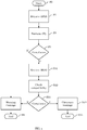
- Fig. 2 shows a process flow involving methods steps of a first embodiment for a method for operating the automated machine 1, e.g. through the control device 102.
- the method for operating the automated machine 1 in particular takes into account safety aspects and preferably leads to a fulfillment of all safety standards required when the automated machine 1 is operated.
- step S0 the process for the automated machine operation 1 starts.
- safety rules SRj applicable to the production units 2, 3, 4, sensor 5 and safety sensor devices 6, 7, 8, 9 are retrieved from the database 101.
- step S3 the control device 102 determines if the implemented safety-sensor devices 6, 7, 8, 9 in terms of their description DSD6 - DSD9 fulfill the safety requirements SRj.
- step S31 the machine configuration in terms of the machine description data MDD is considered during the compliance check in step S3.
- step S4 If the configuration according to all description data MDD, DSDi, DDi complies with the extracted safety rules SRj from the relevant safety standard (see, for example, Fig. 3 ) the process is ended in step S4.
- a warning message is issued in step S5. Additionally, the control device 102 may issue an instruction to stop the operation of the automated machine 1. Generally, the warning message issued in step S5 may trigger an action by maintenance personnel and leads to an end of the method in step S6.
- step S3 If it is decided or checked in step S3 that the combined description data MDD, DSDi, DDi comply with the security rules SRj, no particular action is taken and the operation of the automated machine 1 may pursue according to the control algorithm CALOG. Hence, in step S4, the method is ended.
- a method depicted in Fig. 2 can be carried out after a shut-out due to a safety issue detected by a safety sensor device 6, 7, 8, 9 that occurred in the automated machine 1.
- Fig. 4 shows a process flow involving method steps that can be executed additionally or alternatively to the first embodiment of a method for operating an automated machine.
- step S0 the control process for operating the automated machine 1 starts.
- step S11 in particular the control device 102 (see Fig. 1 ) retrieves the safety sensor description data DSDi.
- the control device 102 obtains the safety sensor information in terms of parameter files, for example IO-link device description data.
- safety rules SRj are retrieved from an available database, such as database 101 shown in Fig. 1 .
- step S3 it is determined if the safety sensors or the safety sensor description DSDi comply with the relevant safety standards for the application under consideration in the automated machine 1.
- the used safety sensors should comply with standards ANSI B11.19, IEC 61496-1/-2, IEC TS62046, ISO 13855 (EN 999). If the control device 102 determines that the safety sensors according to the device description data DSDi do not comply with the relevant safety standards, a warning message is issued in step S5. Hence, the relevant device is marked as unsafe. However, if in step S2 it is determined that the safety sensor complies with safety rules in terms of the safety standards, the machine profile or machine description data MDD is retrieved in step S31.
- the machine description data MDD provides the technical specification of the machine so that in the next step S32, the control device 102 determines if the technical aspects in terms of the machine description data MDD and the suitable safety-sensor devices in terms of the safety-sensor device description data DSDi that passed the compliance test in step S1 match with each other.
- step S33 for example, the controller 102 may determine that the considered sensor device description data for a specific safety-sensor device does not match with the technical-device description data DDi prescribed in the machine description data MDD. Then, a warning message issued in step S5 and the process is ended in step S6.
- step S33 If, however, the compliance check in step S33, results in a match between the machine description data MDD, safety sensor description data DSDi and technical-device description data DDi, a clearance message is issued in step S34. Hence, it is concluded that a safety-sensor device according to the safety sensor description data check through the compliance checks S3 and S33 can be used in the automated machine, and the process is ended in step S35. Eventually, the real safety-sensor device can be placed and integrated into the automated machine, thereby leading to a safe and secure operation of the automated machine according to the relevant safety standards.
- the compliance checks in terms of steps S3 and S33 can be triggered by a change in the automated machine in terms of an environmental change or a change in the operation mode, a change in the sensor or technical device properties. For example, if an operator changes a certain safety-sensor device, the control device 102 will check if the replacement safety sensor fulfills all safety requirements.
- Fig. 5 a process flow involving method steps of a third embodiment for a method or for operating the automated system, e.g. of Fig. 1 , is shown.
- the method steps disclosed and described in Fig. 5 can be executed additionally to the method steps shown in other embodiments.
- the safety sensor description data DSDi is obtained, for example from a web service or a database or document characterizing the safety-sensor devices. This can be, for example, a database provided by a manufacturer of safety-sensor devices.
- a safety standard database 104 as shown in Fig. 1 can be used to retrieve the relevant information regarding the retrieved safety-sensor description data SDSi in step S11.
- the relevant information can be extracted from the standard documents, for example, by a pattern or text recognition module or by a natural language processing module in the control device 102, if safety rules are recorded orally.
- step S21 the relevant safety rules SRj are derived from the retrieved safety rules SRj so that instructions regarding the implementation of safety standards are generated.
- An instruction may comprise a command to implement a certain type of safety sensor for the automated machine.
- step 22 it is determined if the combination of safety sensor description SDSi and machine description MDD according to the instruction generated in a step S21 leads to conflict.
- an instruction may require a specific safety-sensor device to be employed in a position or range, which is unsuitable for the automation process.
- step S22 If there is a conflict detected in step S22, for example the device description data DSDi, DDi and the machine description data MDD can be amended.
- expert data EXD can be used in order to resolve conflicts and provide conflict-free machine description data MDD including the required safety sensor data DSDi and technical-device description data DDi.
- the database 103 shown in Fig. 1 can be implemented as an expert system for resolving those conflicts.
- the database or expert system 103 may deploy machine learning or other artificial intelligence algorithms.
- step S33 again a compliance check as referred to in Fig. 4 is performed. If the combination of safety sensors, technical devices and their arrangement in terms of the machine description data meet the safety standard, a clearance message is issued in step S34. Otherwise, a report is issued in step S51 referring to the safety issues that occurred during the process of Fig. 5 .
- machine description data MDD and device description data DSDi, DDi may form the basis for implementing the actual automated system including the technical devices and sensor devices.
- FIG. 6 and 7 show schematic process flows for aspects of the third embodiment for the method for operating the automated machine depicted in Fig. 5 .
- Fig. 6 and 7 show processes 201 - 211 that may be implemented by functional modules of the controller 102 (see Fig. 1 ). In particular, control processes may continuously monitor the operation of the automated machine 1.
- machine description data MDD may include the type of the machine 1201, machine schematics 202, for example CAD data or 2D or 3D drawings of the machine.
- a machine condition monitoring process 203 determines the health condition, for example with respect to wear or aging effects in the machine parts.
- a danger estimation process 204 considers the machine type 201 together with the overall configuration in terms of machine schematics 202 and identifies possible unsafe or danger-prone regions within the automated machine.
- the input gathered by those processes 201 - 204 are fed into an instruction generation process 205.
- the instruction generation process may implement the method steps S21, S22 and S23 as shown in Fig. 5 and require access to a standards database 206 providing, for example, all relevant standard documents in a computer-readable format (see e.g. Fig. 3 ) on an expert database 207 that can include a process to resolve conflicts between safety standards and the machine description MDD.
- the standard database process 206 and expert database process 207 in particular, consider the description data DSDi, safety rules SRj and generate amended description data DSDi*, DDi*, which are combined into security instructions SINST (208).
- the security instructions SINST provide a draft for the automated machine according to the combined machine description data MDD* and device description data DSDi*, DDi* that fulfill all safety requirements, in particular in the zones estimated in the process 204.
- Fig. 6 and 7 can be considered a simulation of an automated system in terms of the respective description data and safety rules.
- the security instructions 208 are used in a matching process (see step S33 in Fig. 5 ).
- the matching process 209 determines if the device description data DSDi, DDi and machine description data MDD proposed in the security instruction SINST match with each other and can be implemented in a real technical system.
- the safety sensor devices according to the safety-sensor description data defined in the matching process 209 are implemented and coupled within the automated machine 1.
- a self-test process 211 is executed where the automated system and the safety-sensor devices are self-tested and checked as to whether the safety sensors are accepted by the system or do not properly interact.
- a respective report RPT is issued in the reporting process 212 to a user or operator.
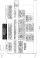
- control device 102 may implement additional processes for monitoring the operation of the automated machine 1 set up according to the defined machine description and device descriptions. This is depicted in Fig. 8 where further processes implemented by the control device 102 (see Fig. 1 ) are shown.
- a machine-monitoring process 301 the operation of the automated machine 1 is monitored.
- the process data including sensor and control data is obtained and logged for a specific time. From historical process data, deviations from proper functioning of the machine can be derived.
- a standards monitoring process 302 monitors if safety standards are changed, for example by the issuance of a new version of a particular standard. To this extent, the standard monitoring process 302, for example, regularly couples to a data depository where the relevant standard documents for automation systems can be retrieved.
- a manual input monitoring process 303 may receive manual input for altering the configuration of the monitored automated system.
- the automated machine safety managing process 304 performs risk assessment process 305, a machine learning process 306, and an optimization process 303. For example, if an anomaly of the monitored automated machine is detected, the safety managing process 304 may trigger a full analysis or self-test of the safety-sensor devices included in the automated machine. Further, if a new or updated security rule is obtained in the standards monitoring process 302, an optimization of the operating automated machine may be necessary. As a result of the safety managing process 304, description data is generated in process 308.
- the safety managing process 304 provides machine description data MDD including references to technical-device description data DDi and safety sensor description data DSDi that preferably lead to an efficient and safe operation of the automated machine according to the control algorithm implemented in the machine controller 10 (see Fig. 1 ).
- Optimizing the parameters comprised in the description data may be based on a machine learning process 306. For example, the occurrence of safety-relevant situations in a technical system can be detected by monitoring the process data.
- Fig. 9 shows an example of a section within an automated system or machine where a production unit 2 has an associated safety sensor 6 in terms of a time-of-flight sensor 6. The time-of-flight sensor 6 monitors the monitoring zone MZ indicated by the dotted lines. Within the monitoring zone MZ, there is a security zone SZ indicated by the section above the dashed line and a warning zone WZ indicated between the dashed line and the dashed-dotted line. For example, it is determined that the automated system implemented according to machine description data MDD, technical-device description data DD2 and safety sensor description data DSD6 reflecting the configuration of Fig. 9 fulfill all safety rules.
- Fig. 9 also shows an operator 11 passing the monitored zone in a trajectory T1 or T2.
- the trajectory T1 passes the warning zone WZ and the monitored zone MZ.
- the trajectory T2 only crosses the monitored zone MZ.
- the machine learning process 306 may use the data obtained by the machine monitoring process 301 and observes that the user 11 is more frequently passing through the monitored zone MZ for the directory D2 than using route T1 entering the warning zone WZ.
- the safety sensor 6 may issue a warning any time trajectory T1 is used. This may result into an interruption of the technical device 2.
- the safety managing process 306 using a machine learning module 306 may now decide that it is unnecessary to extend the warning zone in the orientation of Fig. 9 downwards until the dashed dotted line.
- the safety managing process 304 may generate a safety instruction or proposal to reduce the warning zone WZ towards the security zone SZ. As a result, the user 11 passing trajectory T1 will not trigger a warning any more.
- the safety managing process 304 determines if the proposed improved description data MDD, DSDi and DDi still comply with the relevant safety rules so that the optimized description data can be generated and implemented.
- FIG. 11 A process flow involving method steps implementing the processes depicted with respect to Figs. 8 and 9 is shown in Fig. 11 .
- Fig. 10 shows processes involved in a safety managing process 304 as indicated in Fig. 8 .
- a safety solution process starts in step 401.
- a safety solution is identified which is fed into the safety solution matching process 403.
- the safety solution matching process 403 obtains inputs from a safety feature matching process 500 and a machine configuration matching process 600.
- the safety-related product features in terms of a depository 501, safety-related product functions 502 and an internal matching process 503 are involved.
- machine configuration matching process 600 machine schematics, such as CAD data 601, machine types 602 and a solution database 603, are used by an internal matching process 604.
- a safety performance indicator SPI is calculated and evaluated. If a safest solution for the considered machine configuration is found, a solution is communicated in step 405. Next, the safety devices, in particular the safety-sensor devices, are implemented or set up accordingly in step 406. In the next step 407, a validation process is executed which results in a validated description data to be used in a respective automated machine.
- the validation includes input from the safety solution validation process 700.
- safety-related product functions 701 safety-related product features stored in a depository 702
- the machine type 703 and the solution database 704 are involved in a matching process for the validation 705. If no safety solution is reached in step 404, various other matching processes are repeated in steps 409, 410.
- Fig. 11 shows a more detailed view of a process flow involving method steps of a fifth embodiment of the method for operating an automated machine.
- the fifth embodiment comprises steps and aspects that can be executed in addition to the method steps depicted with respect to other embodiments.
- Fig. 11 elaborates on the steps involved in the safety managing process 304 shown in Fig. 8 .
- safety sensor data SSDi is monitored.
- other process data including the control data and/or the sensor data can be monitored.
- amended safety sensor description data DSDi* is generated in step S81. This can be triggered, for example, by the machine learning of more likely and unlikely scenarios during the operation of the automated machine, as depicted in Fig. 9 .
- the trajectory T1 occurring less frequent than trajectory T2 does not necessarily need to trigger a shutdown of the device 2.
- a proposal for amended safety sensor description data DSDi* is produced.
- step S82 additional sensor information can be retrieved, for example, from a database including device description data DDi according to a specific norm.
- the machine description data MDD is retrieved in step S83. Retrieving may include inputting or downloading a respective description data file.
- step S84 it is determined if the optimized or amended safety sensor description data DSDi* is compatible with security safety standards SR. Further, in step S85, it is determined if the machine description data require certain safety aspects or safety rules. If the machine description data MDD is incompatible with safety standards, the amendment is rejected in step S86. The same occurs, if in step S84 the proposed or amended safety sensor description data DSDi* is not compatible with the safety sensor parameters retrieved in step S82.
- a safety performance indicator SPI is calculated.
- the safety performance indicated SPI for example, provides for a scale from 0 to 10, where 10 is high safety and 0 refers to no safety.
- step S88 If the SPI is increased by the amendment proposed in step S81, an improvement is determined in step S88. Thus, a safer or safe embodiment is achieved and identified in step S90. As a result, the safety-sensor device can be changed in step S91 according to the amended DSDi*.
- step S92 the user is informed in step S92 in terms of a message or signal. If the improvement check in step S88 determines that the SPI is decreased, the amendment is rejected in step S89. Optionally, after rejecting the proposed amendment of step S81, the process can be reiterated indicated by the dashed arrow in Fig. 11 .
- the proposed methods, processes, systems and computer products may lead to an improved safety and/or efficiency of automated systems comprising safety devices in terms of safety-sensor devices and functional units in terms of technical devices.
- the location of the automated machine can be considered when downloading or retrieving the standard documents for the safety rule derivation.
- the disclosed methods and systems can be implemented in a distributed fashion, i.e. the control device 102 (see Fig. 1 ) or the safety managing process 304 (see Fig. 8 ) can be implemented as software services or a cloud service.
- an industrial PCIPC may be functionalized in terms of a computer program product causing the IPC to execute any one of the embodiments of the method for controlling an automated machine.
Landscapes
- Engineering & Computer Science (AREA)
- Physics & Mathematics (AREA)
- General Physics & Mathematics (AREA)
- Automation & Control Theory (AREA)
- General Engineering & Computer Science (AREA)
- Manufacturing & Machinery (AREA)
- Quality & Reliability (AREA)
- Safety Devices In Control Systems (AREA)
- Testing And Monitoring For Control Systems (AREA)
Claims (16)
- System zum Betreiben einer automatisierten Maschine (1), wobei die automatisierte Maschine (1) umfasst:mehrere interagierende technische Vorrichtungen (2, 3, 4, 5), wobei jede technische Vorrichtung (2, 3, 4, 5) geeignet ist, eine zugehörige Aktion auszuführen, wobei jeder technischen Vorrichtung (2, 3, 4, 5) technische Vorrichtungsbeschreibungsdaten (DDi) zugeordnet sind, die Parameter enthalten, die die jeweilige technische Vorrichtung (2, 3, 4, 5) charakterisieren; undmindestens eine Sicherheitssensorvorrichtung (6, 7, 8, 9), die geeignet ist, einen beobachtbaren Zustand eines Raums in und/oder um die automatisierte Maschine (1) zu detektieren und ein Sicherheitsproblem in diesem Raum, eine Fehlfunktion der automatisierten Maschine (1) und/oder der Sicherheitssensorvorrichtung (6, 7, 8, 9) zu detektieren, wobei jeder Sicherheitssensorvorrichtung (6, 7, 8, 9) Sicherheitssensorvorrichtungsbeschreibungsdaten (DSDi) zugeordnet sind, die die Detektion des beobachtbaren Zustands des Raums in und/oder um die automatisierte Maschine (1) durch die jeweilige Sicherheitssensorvorrichtung (6, 7, 8, 9) charakterisieren;wobei das System (100) umfasst:eine Datenbankvorrichtung (101) zum Speichern mehrerer Maschinensicherheitsregeln (SRj) in Form von Anforderungen zwischen Sicherheitssensorvorrichtungsbeschreibungsdaten (DSDi) und technischen Vorrichtungsbeschreibungsdaten (DDi);eine Steuervorrichtung (102), die geeignet ist:die Sicherheitssensorvorrichtungsbeschreibungsdaten (DSDi) und die technischen Vorrichtungsbeschreibungsdaten (DDi) abzurufen, die den technischen Vorrichtungen (2, 3, 4, 5) und den Sicherheitssensorvorrichtungen (6, 7, 8, 9) zugeordnet sind, die in der automatischen Maschine (1) enthalten sind;von der Datenbankvorrichtung (101) Sicherheitsregeln (SRj) abzurufen, die den abgerufenen Sicherheitssensorvorrichtungsbeschreibungsdaten (DSDi) und den technischen Vorrichtungsbeschreibungsdaten (DDi) entsprechen; undzu bestimmen, ob die abgerufenen Sicherheitssensorvorrichtungsbeschreibungsdaten (DSDi) und die technischen Vorrichtungsbeschreibungsdaten (DDi) mit den abgerufenen Sicherheitsregeln (SRj) übereinstimmen;wobei die technischen Vorrichtungsbeschreibungsdaten (DDi) und die Sicherheitssensorvorrichtungsbeschreibungsdaten (DSDi) computerlesbare Informationen über die jeweilige Vorrichtung enthalten.
- System nach Anspruch 1, wobei die Steuervorrichtung ferner geeignet ist:Maschinenbeschreibungsdaten (MDD) zu empfangen, die zumindest das Zusammenwirken der technischen Vorrichtungen (2, 3, 4, 5) charakterisieren; undzu bestimmen, ob die abgerufenen Sicherheitssensorvorrichtungsbeschreibungsdaten (DSDi), die technischen Vorrichtungsbeschreibungsdaten (DDi) und die Maschinenbeschreibungsdaten (MDD) mit den abgerufenen Sicherheitsregeln (SRj) übereinstimmen.
- System nach Anspruch 1 oder 2, wobei die Steuervorrichtung (102) geeignet ist, die technischen Vorrichtungen (2, 3, 4, 5), Sensorvorrichtungen und/oder Sicherheitssensorvorrichtungen (6, 7, 8, 9) zu überwachen, insbesondere um eine Änderung in einer technischen Vorrichtung (2, 3, 4, 5), einer Sensorvorrichtung, einer Sicherheitssensorvorrichtung (6, 7, 8, 9) und/oder eine Änderung der technischen Vorrichtungsbeschreibungsdaten (DDi) oder der Sicherheitssensorvorrichtungsbeschreibungsdaten (DCDi) zu erkennen.
- System nach Anspruch 3, wobei eine Änderung einen Austausch, eine Abnutzung, ein Alter, einen Lebenszyklus, eine Betriebszeit, einen Betriebsmodus, einen Betriebsbereich der technischen Vorrichtung (2, 3, 4, 5), der Sensorvorrichtung oder der Sicherheitssensorvorrichtung (6, 7, 8, 9) umfasst.
- System nach Anspruch 3 oder 4, wobei die Steuervorrichtung (1) geeignet ist, als Reaktion auf eine erkannte Änderung oder Ergänzung festzustellen, ob die geltenden Sicherheitsregeln (SRj) eingehalten werden.
- System nach einem der Ansprüche 1 bis 5, ferner umfassend ein Kommunikationsnetzwerk (11), das geeignet ist, die Steuervorrichtung (102), die technischen Vorrichtungen (2, 3, 4, 5), die Sensorvorrichtungen und/oder die Sicherheitssensorvorrichtungen (6, 7, 8, 9) kommunikativ zu koppeln, insbesondere um Beschreibungsdaten (DSRj, DDj) abzufragen und Steuerdaten (CDj) zu übertragen.
- System nach einem der Ansprüche 1 bis 6, wobei die Beschreibungsdaten (DSDi, DDi) ein vorgegebenes Format aufweisen.
- System nach einem der Ansprüche 1 bis 7, wobei die Maschinensicherheitsregeln (SRj) in einem vorbestimmten computerlesbaren Format empfangen werden, und aus Sicherheitsstandarddokumenten in Textform extrahiert, mittels einer Muster- oder Texterkennung und/oder natürlicher Sprachverarbeitung gescannt werden.
- System nach einem der Ansprüche 1 bis 8, wobei die automatisierte Maschine (1) ferner eine Maschinensteuerungsvorrichtung (10) umfasst, die geeignet ist,
Steuerdaten (CDi) zur Steuerung der mehreren zusammenwirkenden technischen Vorrichtungen (2, 3, 4, 5) zu erzeugen, und
Sensordaten (SD5) und/oder Sicherheitssensordaten (SSD6, SSD7, SSD8, SSD9) zu empfangen, die von der Sicherheitssensorvorrichtung (6, 7, 8, 9) und/oder der Sensorvorrichtung (5) erzeugt wurden;
wobei die Steuerdaten (CDi) in Abhängigkeit von den Sensordaten (SD5) und den Sicherheitssensordaten (SSD6, SSD7, SSD8, SSD9) gemäß einem vorgegebenen Steueralgorithmus (CALG) erzeugt werden. - System nach Anspruch 9, wobei die Steuervorrichtung (102) geeignet ist, die Steuerdaten (CDi), die Sensordaten (SDi) und die Sicherheitssensordaten (SSDi) zu überwachen.
- System nach Anspruch 10, wobei die Steuervorrichtung (102) geeignet ist, in Abhängigkeit von den überwachten Steuerdaten (CDi), Sensordaten (SDi), Sicherheitssensordaten (SSDi), Maschinenbeschreibungsdaten (MDD) und/oder Sicherheitsregeln (SRj) geänderte Sicherheitssensorvorrichtungsbeschreibungsdaten (DSDi*), geänderte technische Vorrichtungsbeschreibungsdaten (DDi*) und/oder geänderte Maschinenbeschreibungsdaten (MDD*) zu erzeugen.
- System nach einem der Ansprüche 1 bis 11, wobei mindestens eine der interagierenden technischen Vorrichtungen (2, 3, 4, 5) eine Aktuatorvorrichtung, eine Robotervorrichtung, eine Transportvorrichtung, eine Fördervorrichtung und/oder eine Sensorvorrichtung (5) ist.
- System nach einem der Ansprüche 1 bis 12, wobei mindestens eine der Sicherheitssensorvorrichtungen (6, 7, 8, 9) eine Lichtvorhangvorrichtung, eine Laufzeitsensorvorrichtung, einen Bewegungsmelder, eine Radar-Sende- und/oder Erfassungsvorrichtung, eine Ultraschall-Sende- und/oder Erfassungsvorrichtung, eine Laserscannervorrichtung, eine photoelektrische Vorrichtung und/oder eine Kameravorrichtung ist.
- Automatisierte Maschine (1), umfassend:mehrere interagierende technische Vorrichtungen (2, 3, 4, 5), wobei jede technische Vorrichtung (2, 3, 4, 5) geeignet ist, eine zugehörige Aktion auszuführen, wobei jeder technischen Vorrichtung (2, 3, 4, 5) technische Vorrichtungsbeschreibungsdaten (DDi) zugeordnet sind, die Parameter enthalten, die die jeweilige technische Vorrichtung (2, 3, 4, 5) charakterisieren; undmindestens eine Sicherheitssensorvorrichtung (6, 7, 8, 9), die geeignet ist, einen beobachtbaren Zustand eines Raums in und/oder um die automatisierte Maschine (1) zu detektieren und ein Sicherheitsproblem in diesem Raum, eine Fehlfunktion der automatisierten Maschine (1) und/oder der Sicherheitssensorvorrichtung (6, 7, 8, 9) zu detektieren, wobei jeder Sicherheitssensorvorrichtung (6, 7, 8, 9) Sicherheitssensorvorrichtungsbeschreibungsdaten (DSDi) zugeordnet sind, die die jeweilige Sicherheitssensorvorrichtung (6, 7, 8, 9) charakterisieren; undein System (100) nach einem der Ansprüche 1 bis 13.
- Verfahren zum Betreiben einer automatisierten Maschine (1), wobei die automatisierte Maschine (1) umfasst:mehrere interagierende technische Vorrichtungen (2, 3, 4, 5), wobei jede technische Vorrichtung (2, 3, 4, 5) geeignet ist, eine zugehörige Aktion auszuführen, wobei jeder technischen Vorrichtung (2, 3, 4, 5) technische Vorrichtungsbeschreibungsdaten (DDi) zugeordnet sind, die Parameter enthalten, die die jeweilige technische Vorrichtung (2, 3, 4, 5) charakterisieren; undmindestens eine Sicherheitssensorvorrichtung (6, 7, 8, 9), die geeignet ist, einen beobachtbaren Zustand eines Raums in und/oder um die automatisierte Maschine (1) zu detektieren und ein Sicherheitsproblem in diesem Raum, eine Fehlfunktion der automatisierten Maschine (1) und/oder der Sicherheitssensorvorrichtung (6, 7, 8, 9) zu detektieren, wobei jeder Sicherheitssensorvorrichtung (6, 7, 8, 9) Sicherheitssensorvorrichtungsbeschreibungsdaten (DSDi) zugeordnet sind, die die Detektion des beobachtbaren Zustands des Raums in und/oder um die automatisierte Maschine (1) durch die jeweilige Sicherheitssensorvorrichtung (6, 7, 8, 9) charakterisieren;wobei das Verfahren umfasst:Abrufen, aus einer Datenbank (101), die mehrere Maschinensicherheitsregeln (SRj) in Form von Anforderungen zwischen Sicherheitssensorvorrichtungsbeschreibungsdaten (DSDi) und technischen Vorrichtungsbeschreibungsdaten (DDi) speichert, von Sicherheitssensorvorrichtungsbeschreibungsdaten (DSDi) und technischen Vorrichtungsbeschreibungsdaten (DDi), die den technischen Vorrichtungen (2, 3, 4, 5) und den Sicherheitssensorvorrichtungen (6, 7, 8, 9) zugeordnet sind, die in der automatisierten Maschine (1) enthalten sind;Abrufen, aus der Datenbank (10), von Sicherheitsregeln (SRj), die den abgerufenen Sicherheitssensorvorrichtungsbeschreibungsdaten (DSDi) und den technischen Vorrichtungsbeschreibungsdaten (DDi) entsprechen; undBestimmen, ob die abgerufenen Sicherheitssensorvorrichtungsbeschreibungsdaten (DSDi) und die technischen Vorrichtungsbeschreibungsdaten (DDi) mit den abgerufenen Sicherheitsregeln (SRj) übereinstimmen;wobei die technischen Vorrichtungsbeschreibungsdaten (DDi) und die Sicherheitssensorvorrichtungsbeschreibungsdaten (DSDi) computerlesbare Informationen über die jeweilige Vorrichtung enthalten.
- Computerprogrammprodukt (105), das computerlesbare Anweisungen enthält, die ein Computersystem (102), das eine oder mehrere Verarbeitungsvorrichtungen (104) enthält, in Reaktion auf die Ausführung der computerlesbaren Anweisungen dazu zu veranlassen:aus einer Datenbank (101), die mehrere Maschinensicherheitsregeln (SRj) in Form von Anforderungen zwischen Sicherheitssensorvorrichtungsbeschreibungsdaten (DSDi) und technischen Vorrichtungsbeschreibungsdaten (DDi) speichert, Sicherheitssensorvorrichtungsbeschreibungsdaten (DSDi) und technischen Vorrichtungsbeschreibungsdaten (DDi), die den technischen Vorrichtungen (2, 3, 4, 5) und den Sicherheitssensorvorrichtungen (6, 7, 8, 9) zugeordnet sind, die in der automatisierten Maschine (1) enthalten sind, abzurufen;aus der Datenbank (10) Sicherheitsregeln (SRj) abzurufen, die den abgerufenen Sicherheitssensorvorrichtungsbeschreibungsdaten (DSDi) und den technischen Vorrichtungsbeschreibungsdaten (DDi) entsprechen; undzu bestimmen, ob die abgerufenen Sicherheitssensorvorrichtungsbeschreibungsdaten (DSDi) und die technischen Vorrichtungsbeschreibungsdaten (DDi) mit den abgerufenen Sicherheitsregeln (SRj) übereinstimmen;wobei die automatisierte Maschine (1) umfasst:mehrere interagierende technische Vorrichtungen (2, 3, 4, 5), wobei jede technische Vorrichtung (2, 3, 4, 5) geeignet ist, eine zugehörige Aktion auszuführen, wobei jeder technischen Vorrichtung (2, 3, 4, 5) technische Vorrichtungsbeschreibungsdaten (DDi) zugeordnet sind, die Parameter enthalten, die die jeweilige technische Vorrichtung (2, 3, 4, 5) charakterisieren; undmindestens eine Sicherheitssensorvorrichtung (6, 7, 8, 9), die geeignet ist, einen beobachtbaren Zustand eines Raums in und/oder um die automatisierte Maschine (1) zu detektieren und ein Sicherheitsproblem in diesem Raum, eine Fehlfunktion der automatisierten Maschine (1) und/oder der Sicherheitssensorvorrichtung (6, 7, 8, 9) zu detektieren, wobei jeder Sicherheitssensorvorrichtung (6, 7, 8, 9) Sicherheitssensorvorrichtungsbeschreibungsdaten (DSDi) zugeordnet sind, die die Detektion des beobachtbaren Zustands des Raums in und/oder um die automatisierte Maschine (1) durch die jeweilige Sicherheitssensorvorrichtung (6, 7, 8, 9) charakterisieren;wobei die technischen Vorrichtungsbeschreibungsdaten (DDi) und die Sicherheitssensorvorrichtungsbeschreibungsdaten (DSDi) computerlesbare Informationen über die jeweilige Vorrichtung enthalten.
Priority Applications (5)
| Application Number | Priority Date | Filing Date | Title |
|---|---|---|---|
| EP19183402.7A EP3757693B9 (de) | 2019-06-28 | 2019-06-28 | System und verfahren zum betrieb einer automatisierten maschine, automatisierte maschine und computerprogrammprodukt |
| JP2021574273A JP7342976B2 (ja) | 2019-06-28 | 2020-05-26 | 自動機械を運転するためのシステムおよび方法、自動機械、およびコンピュータプログラム製品 |
| US17/615,373 US12181860B2 (en) | 2019-06-28 | 2020-05-26 | System and method for operating an automated machine, automated machine, and computer-program product |
| PCT/IB2020/054962 WO2020260977A1 (en) | 2019-06-28 | 2020-05-26 | System and method for operating an automated machine, automated machine, and computer-program product |
| CN202080039817.3A CN113924534B (zh) | 2019-06-28 | 2020-05-26 | 用于操作自动化机器的系统和方法、自动化机器及计算机可读存储介质 |
Applications Claiming Priority (1)
| Application Number | Priority Date | Filing Date | Title |
|---|---|---|---|
| EP19183402.7A EP3757693B9 (de) | 2019-06-28 | 2019-06-28 | System und verfahren zum betrieb einer automatisierten maschine, automatisierte maschine und computerprogrammprodukt |
Publications (3)
| Publication Number | Publication Date |
|---|---|
| EP3757693A1 EP3757693A1 (de) | 2020-12-30 |
| EP3757693B1 true EP3757693B1 (de) | 2021-06-09 |
| EP3757693B9 EP3757693B9 (de) | 2021-09-08 |
Family
ID=67145534
Family Applications (1)
| Application Number | Title | Priority Date | Filing Date |
|---|---|---|---|
| EP19183402.7A Active EP3757693B9 (de) | 2019-06-28 | 2019-06-28 | System und verfahren zum betrieb einer automatisierten maschine, automatisierte maschine und computerprogrammprodukt |
Country Status (5)
| Country | Link |
|---|---|
| US (1) | US12181860B2 (de) |
| EP (1) | EP3757693B9 (de) |
| JP (1) | JP7342976B2 (de) |
| CN (1) | CN113924534B (de) |
| WO (1) | WO2020260977A1 (de) |
Families Citing this family (1)
| Publication number | Priority date | Publication date | Assignee | Title |
|---|---|---|---|---|
| DE102023101668A1 (de) | 2023-01-24 | 2024-07-25 | Krohne Messtechnik Gmbh | Verfahren zum Betreiben eines Feldgerätes der Prozessmesstechnik und Abfüllanlage, mit der das Verfahren ausgeführt wird |
Family Cites Families (16)
| Publication number | Priority date | Publication date | Assignee | Title |
|---|---|---|---|---|
| US5920861A (en) * | 1997-02-25 | 1999-07-06 | Intertrust Technologies Corp. | Techniques for defining using and manipulating rights management data structures |
| WO2011048380A1 (en) * | 2009-10-23 | 2011-04-28 | Bae Systems Plc | Safety management system |
| EP2317412A1 (de) * | 2009-10-23 | 2011-05-04 | BAE SYSTEMS plc | Sicherheitsverwaltungssystem |
| JP5407882B2 (ja) | 2010-01-14 | 2014-02-05 | オムロン株式会社 | 制御システム |
| CN102708249B (zh) * | 2012-05-10 | 2014-05-21 | 三一集团有限公司 | 一种产品模块化配置方法及系统 |
| US20140300926A1 (en) * | 2013-04-09 | 2014-10-09 | Xerox Corporation | Methods and systems for automatic selection of a production device configuration in a production environment |
| EP3023846A1 (de) * | 2014-11-18 | 2016-05-25 | Moog Unna GmbH | Elektromechanisches Antriebssystem |
| US10081106B2 (en) * | 2015-11-24 | 2018-09-25 | X Development Llc | Safety system for integrated human/robotic environments |
| EP3200122B1 (de) * | 2016-01-26 | 2022-06-22 | Sick Ag | Optoelektronischer sensor und verfahren zur sicheren erkennung von objekten einer mindestgrösse |
| US10051349B2 (en) | 2016-04-05 | 2018-08-14 | Tyco Fire & Security Gmbh | Sensor based system and method for premises safety and operational profiling based on drift analysis |
| US10204226B2 (en) | 2016-12-07 | 2019-02-12 | General Electric Company | Feature and boundary tuning for threat detection in industrial asset control system |
| JP6911408B2 (ja) * | 2017-03-13 | 2021-07-28 | オムロン株式会社 | 評価システム、安全コントローラ、評価プログラム、および、評価方法 |
| JP6776164B2 (ja) * | 2017-03-28 | 2020-10-28 | 株式会社東芝 | 管理装置、管理方法およびプログラム |
| JP6866773B2 (ja) | 2017-06-01 | 2021-04-28 | オムロン株式会社 | 安全制御装置、安全制御装置の制御方法、情報処理プログラム、および記録媒体 |
| CN107657681A (zh) | 2017-09-19 | 2018-02-02 | 金蝶软件(中国)有限公司 | 生产设备参数调整方法及装置、计算机装置及可读存储器 |
| CN108415381A (zh) | 2018-02-10 | 2018-08-17 | 苏州宏软信息技术有限公司 | 一种用于机加工车间的分布式远程监控系统及监控方法 |
-
2019
- 2019-06-28 EP EP19183402.7A patent/EP3757693B9/de active Active
-
2020
- 2020-05-26 WO PCT/IB2020/054962 patent/WO2020260977A1/en not_active Ceased
- 2020-05-26 JP JP2021574273A patent/JP7342976B2/ja active Active
- 2020-05-26 US US17/615,373 patent/US12181860B2/en active Active
- 2020-05-26 CN CN202080039817.3A patent/CN113924534B/zh active Active
Non-Patent Citations (1)
| Title |
|---|
| None * |
Also Published As
| Publication number | Publication date |
|---|---|
| CN113924534B (zh) | 2024-10-29 |
| JP2022536396A (ja) | 2022-08-15 |
| EP3757693A1 (de) | 2020-12-30 |
| JP7342976B2 (ja) | 2023-09-12 |
| EP3757693B9 (de) | 2021-09-08 |
| US12181860B2 (en) | 2024-12-31 |
| WO2020260977A1 (en) | 2020-12-30 |
| US20220229423A1 (en) | 2022-07-21 |
| CN113924534A (zh) | 2022-01-11 |
Similar Documents
| Publication | Publication Date | Title |
|---|---|---|
| KR102373787B1 (ko) | 고장 예측 시스템의 고장 유형 빅데이터를 이용한 기계설비의 잠재적 고장 예측 방법 | |
| Caiazzo et al. | An IoT-based and cloud-assisted AI-driven monitoring platform for smart manufacturing: design architecture and experimental validation | |
| KR102464762B1 (ko) | 경험적 공유 지식 기반의 인공지능을 활용한 설비고장 예지보전 방법 | |
| Bayar et al. | Fault detection, diagnosis and recovery using Artificial Immune Systems: A review | |
| EP2345015B1 (de) | System und verfahren zur verbesserten koordination zwischen kontroll- und sicherheitssystemen | |
| CN102652310B (zh) | 自动化管理系统和方法 | |
| US10776706B2 (en) | Cost-driven system and method for predictive equipment failure detection | |
| US20110166912A1 (en) | Plant analysis system | |
| EP4073979B1 (de) | Verfahren zur überwachung und/oder steuerung einer oder mehrerer chemischer anlage(n) | |
| CN104238491B (zh) | 用于基于工业自动化流的数据处理的信息平台 | |
| Sharma | Enhancing industrial automation and safety through real-time monitoring and control systems | |
| EP4006674B1 (de) | Verfahren und system zur instandhaltung einer anlage | |
| CN118445106B (zh) | 一种煤机设备的在线状态监测方法及健康管理系统 | |
| EP4073606B1 (de) | Fertigungssystem zur überwachung und/oder steuerung einer oder mehrerer chemischer anlagen | |
| EP3757693B9 (de) | System und verfahren zum betrieb einer automatisierten maschine, automatisierte maschine und computerprogrammprodukt | |
| Wilch et al. | A distributed framework for knowledge-driven root-cause analysis on evolving alarm data–an industrial case study | |
| CN202956626U (zh) | 用于监控多个机床的机器状态的系统 | |
| CN110891039B (zh) | 一种基于lm神经网络的煤矿监控系统安全预警方法 | |
| ENGİN | FUNCTIONAL SAFETY IN PROGRAMMABLE LOGIC CONTROLLERS | |
| CN118859887B (zh) | 兼容多个dcs系统的自动化监控平台和方法 | |
| Elshorbagy | Real-Time Anomaly Detection and Autonomous Response in Industrial IoT | |
| US20250085672A1 (en) | Ai-based orchestration in industrial control systems | |
| KR102649422B1 (ko) | 운전 정보 제공 장치 및 방법 | |
| CN119526388A (zh) | 故障处理方法、机器人及存储介质 | |
| KR20250091674A (ko) | 정밀가공설비의 ai모델이 적용되는 플랫폼 시스템 |
Legal Events
| Date | Code | Title | Description |
|---|---|---|---|
| STAA | Information on the status of an ep patent application or granted ep patent |
Free format text: STATUS: EXAMINATION IS IN PROGRESS |
|
| PUAI | Public reference made under article 153(3) epc to a published international application that has entered the european phase |
Free format text: ORIGINAL CODE: 0009012 |
|
| 17P | Request for examination filed |
Effective date: 20200218 |
|
| AK | Designated contracting states |
Kind code of ref document: A1 Designated state(s): AL AT BE BG CH CY CZ DE DK EE ES FI FR GB GR HR HU IE IS IT LI LT LU LV MC MK MT NL NO PL PT RO RS SE SI SK SM TR |
|
| AX | Request for extension of the european patent |
Extension state: BA ME |
|
| GRAP | Despatch of communication of intention to grant a patent |
Free format text: ORIGINAL CODE: EPIDOSNIGR1 |
|
| STAA | Information on the status of an ep patent application or granted ep patent |
Free format text: STATUS: GRANT OF PATENT IS INTENDED |
|
| INTG | Intention to grant announced |
Effective date: 20210330 |
|
| GRAS | Grant fee paid |
Free format text: ORIGINAL CODE: EPIDOSNIGR3 |
|
| GRAA | (expected) grant |
Free format text: ORIGINAL CODE: 0009210 |
|
| STAA | Information on the status of an ep patent application or granted ep patent |
Free format text: STATUS: THE PATENT HAS BEEN GRANTED |
|
| AK | Designated contracting states |
Kind code of ref document: B1 Designated state(s): AL AT BE BG CH CY CZ DE DK EE ES FI FR GB GR HR HU IE IS IT LI LT LU LV MC MK MT NL NO PL PT RO RS SE SI SK SM TR |
|
| REG | Reference to a national code |
Ref country code: GB Ref legal event code: FG4D |
|
| REG | Reference to a national code |
Ref country code: CH Ref legal event code: EP Ref country code: AT Ref legal event code: REF Ref document number: 1401019 Country of ref document: AT Kind code of ref document: T Effective date: 20210615 |
|
| REG | Reference to a national code |
Ref country code: DE Ref legal event code: R096 Ref document number: 602019005205 Country of ref document: DE |
|
| REG | Reference to a national code |
Ref country code: IE Ref legal event code: FG4D |
|
| REG | Reference to a national code |
Ref country code: CH Ref legal event code: PK Free format text: BERICHTIGUNG B9 |
|
| REG | Reference to a national code |
Ref country code: LT Ref legal event code: MG9D |
|
| PG25 | Lapsed in a contracting state [announced via postgrant information from national office to epo] |
Ref country code: BG Free format text: LAPSE BECAUSE OF FAILURE TO SUBMIT A TRANSLATION OF THE DESCRIPTION OR TO PAY THE FEE WITHIN THE PRESCRIBED TIME-LIMIT Effective date: 20210909 Ref country code: FI Free format text: LAPSE BECAUSE OF FAILURE TO SUBMIT A TRANSLATION OF THE DESCRIPTION OR TO PAY THE FEE WITHIN THE PRESCRIBED TIME-LIMIT Effective date: 20210609 Ref country code: LT Free format text: LAPSE BECAUSE OF FAILURE TO SUBMIT A TRANSLATION OF THE DESCRIPTION OR TO PAY THE FEE WITHIN THE PRESCRIBED TIME-LIMIT Effective date: 20210609 Ref country code: HR Free format text: LAPSE BECAUSE OF FAILURE TO SUBMIT A TRANSLATION OF THE DESCRIPTION OR TO PAY THE FEE WITHIN THE PRESCRIBED TIME-LIMIT Effective date: 20210609 |
|
| REG | Reference to a national code |
Ref country code: AT Ref legal event code: MK05 Ref document number: 1401019 Country of ref document: AT Kind code of ref document: T Effective date: 20210609 |
|
| REG | Reference to a national code |
Ref country code: NL Ref legal event code: MP Effective date: 20210609 |
|
| PG25 | Lapsed in a contracting state [announced via postgrant information from national office to epo] |
Ref country code: RS Free format text: LAPSE BECAUSE OF FAILURE TO SUBMIT A TRANSLATION OF THE DESCRIPTION OR TO PAY THE FEE WITHIN THE PRESCRIBED TIME-LIMIT Effective date: 20210609 Ref country code: SE Free format text: LAPSE BECAUSE OF FAILURE TO SUBMIT A TRANSLATION OF THE DESCRIPTION OR TO PAY THE FEE WITHIN THE PRESCRIBED TIME-LIMIT Effective date: 20210609 Ref country code: NO Free format text: LAPSE BECAUSE OF FAILURE TO SUBMIT A TRANSLATION OF THE DESCRIPTION OR TO PAY THE FEE WITHIN THE PRESCRIBED TIME-LIMIT Effective date: 20210909 Ref country code: LV Free format text: LAPSE BECAUSE OF FAILURE TO SUBMIT A TRANSLATION OF THE DESCRIPTION OR TO PAY THE FEE WITHIN THE PRESCRIBED TIME-LIMIT Effective date: 20210609 Ref country code: GR Free format text: LAPSE BECAUSE OF FAILURE TO SUBMIT A TRANSLATION OF THE DESCRIPTION OR TO PAY THE FEE WITHIN THE PRESCRIBED TIME-LIMIT Effective date: 20210910 |
|
| PG25 | Lapsed in a contracting state [announced via postgrant information from national office to epo] |
Ref country code: EE Free format text: LAPSE BECAUSE OF FAILURE TO SUBMIT A TRANSLATION OF THE DESCRIPTION OR TO PAY THE FEE WITHIN THE PRESCRIBED TIME-LIMIT Effective date: 20210609 Ref country code: ES Free format text: LAPSE BECAUSE OF FAILURE TO SUBMIT A TRANSLATION OF THE DESCRIPTION OR TO PAY THE FEE WITHIN THE PRESCRIBED TIME-LIMIT Effective date: 20210609 Ref country code: SK Free format text: LAPSE BECAUSE OF FAILURE TO SUBMIT A TRANSLATION OF THE DESCRIPTION OR TO PAY THE FEE WITHIN THE PRESCRIBED TIME-LIMIT Effective date: 20210609 Ref country code: PT Free format text: LAPSE BECAUSE OF FAILURE TO SUBMIT A TRANSLATION OF THE DESCRIPTION OR TO PAY THE FEE WITHIN THE PRESCRIBED TIME-LIMIT Effective date: 20211011 Ref country code: RO Free format text: LAPSE BECAUSE OF FAILURE TO SUBMIT A TRANSLATION OF THE DESCRIPTION OR TO PAY THE FEE WITHIN THE PRESCRIBED TIME-LIMIT Effective date: 20210609 Ref country code: NL Free format text: LAPSE BECAUSE OF FAILURE TO SUBMIT A TRANSLATION OF THE DESCRIPTION OR TO PAY THE FEE WITHIN THE PRESCRIBED TIME-LIMIT Effective date: 20210609 Ref country code: SM Free format text: LAPSE BECAUSE OF FAILURE TO SUBMIT A TRANSLATION OF THE DESCRIPTION OR TO PAY THE FEE WITHIN THE PRESCRIBED TIME-LIMIT Effective date: 20210609 Ref country code: AT Free format text: LAPSE BECAUSE OF FAILURE TO SUBMIT A TRANSLATION OF THE DESCRIPTION OR TO PAY THE FEE WITHIN THE PRESCRIBED TIME-LIMIT Effective date: 20210609 Ref country code: CZ Free format text: LAPSE BECAUSE OF FAILURE TO SUBMIT A TRANSLATION OF THE DESCRIPTION OR TO PAY THE FEE WITHIN THE PRESCRIBED TIME-LIMIT Effective date: 20210609 |
|
| PG25 | Lapsed in a contracting state [announced via postgrant information from national office to epo] |
Ref country code: PL Free format text: LAPSE BECAUSE OF FAILURE TO SUBMIT A TRANSLATION OF THE DESCRIPTION OR TO PAY THE FEE WITHIN THE PRESCRIBED TIME-LIMIT Effective date: 20210609 |
|
| REG | Reference to a national code |
Ref country code: BE Ref legal event code: MM Effective date: 20210630 |
|
| REG | Reference to a national code |
Ref country code: DE Ref legal event code: R097 Ref document number: 602019005205 Country of ref document: DE |
|
| PG25 | Lapsed in a contracting state [announced via postgrant information from national office to epo] |
Ref country code: MC Free format text: LAPSE BECAUSE OF FAILURE TO SUBMIT A TRANSLATION OF THE DESCRIPTION OR TO PAY THE FEE WITHIN THE PRESCRIBED TIME-LIMIT Effective date: 20210609 Ref country code: LU Free format text: LAPSE BECAUSE OF NON-PAYMENT OF DUE FEES Effective date: 20210628 |
|
| PLBE | No opposition filed within time limit |
Free format text: ORIGINAL CODE: 0009261 |
|
| STAA | Information on the status of an ep patent application or granted ep patent |
Free format text: STATUS: NO OPPOSITION FILED WITHIN TIME LIMIT |
|
| PG25 | Lapsed in a contracting state [announced via postgrant information from national office to epo] |
Ref country code: IE Free format text: LAPSE BECAUSE OF NON-PAYMENT OF DUE FEES Effective date: 20210628 Ref country code: DK Free format text: LAPSE BECAUSE OF FAILURE TO SUBMIT A TRANSLATION OF THE DESCRIPTION OR TO PAY THE FEE WITHIN THE PRESCRIBED TIME-LIMIT Effective date: 20210609 |
|
| 26N | No opposition filed |
Effective date: 20220310 |
|
| PG25 | Lapsed in a contracting state [announced via postgrant information from national office to epo] |
Ref country code: AL Free format text: LAPSE BECAUSE OF FAILURE TO SUBMIT A TRANSLATION OF THE DESCRIPTION OR TO PAY THE FEE WITHIN THE PRESCRIBED TIME-LIMIT Effective date: 20210609 |
|
| PG25 | Lapsed in a contracting state [announced via postgrant information from national office to epo] |
Ref country code: IT Free format text: LAPSE BECAUSE OF FAILURE TO SUBMIT A TRANSLATION OF THE DESCRIPTION OR TO PAY THE FEE WITHIN THE PRESCRIBED TIME-LIMIT Effective date: 20210609 Ref country code: FR Free format text: LAPSE BECAUSE OF NON-PAYMENT OF DUE FEES Effective date: 20210809 Ref country code: BE Free format text: LAPSE BECAUSE OF NON-PAYMENT OF DUE FEES Effective date: 20210630 |
|
| REG | Reference to a national code |
Ref country code: CH Ref legal event code: PL |
|
| PG25 | Lapsed in a contracting state [announced via postgrant information from national office to epo] |
Ref country code: LI Free format text: LAPSE BECAUSE OF NON-PAYMENT OF DUE FEES Effective date: 20220630 Ref country code: CH Free format text: LAPSE BECAUSE OF NON-PAYMENT OF DUE FEES Effective date: 20220630 |
|
| PG25 | Lapsed in a contracting state [announced via postgrant information from national office to epo] |
Ref country code: CY Free format text: LAPSE BECAUSE OF FAILURE TO SUBMIT A TRANSLATION OF THE DESCRIPTION OR TO PAY THE FEE WITHIN THE PRESCRIBED TIME-LIMIT Effective date: 20210609 |
|
| PG25 | Lapsed in a contracting state [announced via postgrant information from national office to epo] |
Ref country code: HU Free format text: LAPSE BECAUSE OF FAILURE TO SUBMIT A TRANSLATION OF THE DESCRIPTION OR TO PAY THE FEE WITHIN THE PRESCRIBED TIME-LIMIT; INVALID AB INITIO Effective date: 20190628 |
|
| GBPC | Gb: european patent ceased through non-payment of renewal fee |
Effective date: 20230628 |
|
| PG25 | Lapsed in a contracting state [announced via postgrant information from national office to epo] |
Ref country code: MK Free format text: LAPSE BECAUSE OF FAILURE TO SUBMIT A TRANSLATION OF THE DESCRIPTION OR TO PAY THE FEE WITHIN THE PRESCRIBED TIME-LIMIT Effective date: 20210609 Ref country code: GB Free format text: LAPSE BECAUSE OF NON-PAYMENT OF DUE FEES Effective date: 20230628 |
|
| PG25 | Lapsed in a contracting state [announced via postgrant information from national office to epo] |
Ref country code: TR Free format text: LAPSE BECAUSE OF FAILURE TO SUBMIT A TRANSLATION OF THE DESCRIPTION OR TO PAY THE FEE WITHIN THE PRESCRIBED TIME-LIMIT Effective date: 20210609 |
|
| PG25 | Lapsed in a contracting state [announced via postgrant information from national office to epo] |
Ref country code: MT Free format text: LAPSE BECAUSE OF FAILURE TO SUBMIT A TRANSLATION OF THE DESCRIPTION OR TO PAY THE FEE WITHIN THE PRESCRIBED TIME-LIMIT Effective date: 20210609 |
|
| PGFP | Annual fee paid to national office [announced via postgrant information from national office to epo] |
Ref country code: DE Payment date: 20250618 Year of fee payment: 7 |