EP3757612A1 - Vehicle radar system for detecting dangerous goods - Google Patents
Vehicle radar system for detecting dangerous goods Download PDFInfo
- Publication number
- EP3757612A1 EP3757612A1 EP19758003.8A EP19758003A EP3757612A1 EP 3757612 A1 EP3757612 A1 EP 3757612A1 EP 19758003 A EP19758003 A EP 19758003A EP 3757612 A1 EP3757612 A1 EP 3757612A1
- Authority
- EP
- European Patent Office
- Prior art keywords
- vehicle
- warning
- radar system
- navigation device
- black box
- Prior art date
- Legal status (The legal status is an assumption and is not a legal conclusion. Google has not performed a legal analysis and makes no representation as to the accuracy of the status listed.)
- Withdrawn
Links
- 238000004891 communication Methods 0.000 claims abstract description 24
- 238000001514 detection method Methods 0.000 claims description 8
- 238000000034 method Methods 0.000 claims description 7
- 238000003384 imaging method Methods 0.000 claims description 5
- 230000005540 biological transmission Effects 0.000 claims description 4
- 238000001228 spectrum Methods 0.000 claims description 3
- 208000033748 Device issues Diseases 0.000 claims 3
- 230000007423 decrease Effects 0.000 description 2
- 238000010586 diagram Methods 0.000 description 2
- 230000000694 effects Effects 0.000 description 2
- 230000007613 environmental effect Effects 0.000 description 2
- 230000002159 abnormal effect Effects 0.000 description 1
- 230000005856 abnormality Effects 0.000 description 1
- 238000009434 installation Methods 0.000 description 1
- 238000004519 manufacturing process Methods 0.000 description 1
- 238000012986 modification Methods 0.000 description 1
- 230000004048 modification Effects 0.000 description 1
- 238000012544 monitoring process Methods 0.000 description 1
- 230000029058 respiratory gaseous exchange Effects 0.000 description 1
Images

Classifications
-
- G—PHYSICS
- G01—MEASURING; TESTING
- G01S—RADIO DIRECTION-FINDING; RADIO NAVIGATION; DETERMINING DISTANCE OR VELOCITY BY USE OF RADIO WAVES; LOCATING OR PRESENCE-DETECTING BY USE OF THE REFLECTION OR RERADIATION OF RADIO WAVES; ANALOGOUS ARRANGEMENTS USING OTHER WAVES
- G01S7/00—Details of systems according to groups G01S13/00, G01S15/00, G01S17/00
- G01S7/003—Transmission of data between radar, sonar or lidar systems and remote stations
-
- G—PHYSICS
- G01—MEASURING; TESTING
- G01S—RADIO DIRECTION-FINDING; RADIO NAVIGATION; DETERMINING DISTANCE OR VELOCITY BY USE OF RADIO WAVES; LOCATING OR PRESENCE-DETECTING BY USE OF THE REFLECTION OR RERADIATION OF RADIO WAVES; ANALOGOUS ARRANGEMENTS USING OTHER WAVES
- G01S13/00—Systems using the reflection or reradiation of radio waves, e.g. radar systems; Analogous systems using reflection or reradiation of waves whose nature or wavelength is irrelevant or unspecified
- G01S13/88—Radar or analogous systems specially adapted for specific applications
- G01S13/93—Radar or analogous systems specially adapted for specific applications for anti-collision purposes
- G01S13/931—Radar or analogous systems specially adapted for specific applications for anti-collision purposes of land vehicles
-
- B—PERFORMING OPERATIONS; TRANSPORTING
- B60—VEHICLES IN GENERAL
- B60R—VEHICLES, VEHICLE FITTINGS, OR VEHICLE PARTS, NOT OTHERWISE PROVIDED FOR
- B60R11/00—Arrangements for holding or mounting articles, not otherwise provided for
- B60R11/02—Arrangements for holding or mounting articles, not otherwise provided for for radio sets, television sets, telephones, or the like; Arrangement of controls thereof
-
- B—PERFORMING OPERATIONS; TRANSPORTING
- B60—VEHICLES IN GENERAL
- B60R—VEHICLES, VEHICLE FITTINGS, OR VEHICLE PARTS, NOT OTHERWISE PROVIDED FOR
- B60R11/00—Arrangements for holding or mounting articles, not otherwise provided for
- B60R11/02—Arrangements for holding or mounting articles, not otherwise provided for for radio sets, television sets, telephones, or the like; Arrangement of controls thereof
- B60R11/0211—Arrangements for holding or mounting articles, not otherwise provided for for radio sets, television sets, telephones, or the like; Arrangement of controls thereof for record carriers apparatus, e.g. video recorders, tape players or CD players
-
- B—PERFORMING OPERATIONS; TRANSPORTING
- B60—VEHICLES IN GENERAL
- B60R—VEHICLES, VEHICLE FITTINGS, OR VEHICLE PARTS, NOT OTHERWISE PROVIDED FOR
- B60R11/00—Arrangements for holding or mounting articles, not otherwise provided for
- B60R11/02—Arrangements for holding or mounting articles, not otherwise provided for for radio sets, television sets, telephones, or the like; Arrangement of controls thereof
- B60R11/0258—Arrangements for holding or mounting articles, not otherwise provided for for radio sets, television sets, telephones, or the like; Arrangement of controls thereof for navigation systems
-
- B—PERFORMING OPERATIONS; TRANSPORTING
- B60—VEHICLES IN GENERAL
- B60R—VEHICLES, VEHICLE FITTINGS, OR VEHICLE PARTS, NOT OTHERWISE PROVIDED FOR
- B60R16/00—Electric or fluid circuits specially adapted for vehicles and not otherwise provided for; Arrangement of elements of electric or fluid circuits specially adapted for vehicles and not otherwise provided for
- B60R16/02—Electric or fluid circuits specially adapted for vehicles and not otherwise provided for; Arrangement of elements of electric or fluid circuits specially adapted for vehicles and not otherwise provided for electric constitutive elements
- B60R16/023—Electric or fluid circuits specially adapted for vehicles and not otherwise provided for; Arrangement of elements of electric or fluid circuits specially adapted for vehicles and not otherwise provided for electric constitutive elements for transmission of signals between vehicle parts or subsystems
- B60R16/0239—Electronic boxes
-
- B—PERFORMING OPERATIONS; TRANSPORTING
- B60—VEHICLES IN GENERAL
- B60W—CONJOINT CONTROL OF VEHICLE SUB-UNITS OF DIFFERENT TYPE OR DIFFERENT FUNCTION; CONTROL SYSTEMS SPECIALLY ADAPTED FOR HYBRID VEHICLES; ROAD VEHICLE DRIVE CONTROL SYSTEMS FOR PURPOSES NOT RELATED TO THE CONTROL OF A PARTICULAR SUB-UNIT
- B60W30/00—Purposes of road vehicle drive control systems not related to the control of a particular sub-unit, e.g. of systems using conjoint control of vehicle sub-units
- B60W30/08—Active safety systems predicting or avoiding probable or impending collision or attempting to minimise its consequences
-
- B—PERFORMING OPERATIONS; TRANSPORTING
- B60—VEHICLES IN GENERAL
- B60W—CONJOINT CONTROL OF VEHICLE SUB-UNITS OF DIFFERENT TYPE OR DIFFERENT FUNCTION; CONTROL SYSTEMS SPECIALLY ADAPTED FOR HYBRID VEHICLES; ROAD VEHICLE DRIVE CONTROL SYSTEMS FOR PURPOSES NOT RELATED TO THE CONTROL OF A PARTICULAR SUB-UNIT
- B60W30/00—Purposes of road vehicle drive control systems not related to the control of a particular sub-unit, e.g. of systems using conjoint control of vehicle sub-units
- B60W30/08—Active safety systems predicting or avoiding probable or impending collision or attempting to minimise its consequences
- B60W30/09—Taking automatic action to avoid collision, e.g. braking and steering
-
- B—PERFORMING OPERATIONS; TRANSPORTING
- B60—VEHICLES IN GENERAL
- B60W—CONJOINT CONTROL OF VEHICLE SUB-UNITS OF DIFFERENT TYPE OR DIFFERENT FUNCTION; CONTROL SYSTEMS SPECIALLY ADAPTED FOR HYBRID VEHICLES; ROAD VEHICLE DRIVE CONTROL SYSTEMS FOR PURPOSES NOT RELATED TO THE CONTROL OF A PARTICULAR SUB-UNIT
- B60W40/00—Estimation or calculation of non-directly measurable driving parameters for road vehicle drive control systems not related to the control of a particular sub unit, e.g. by using mathematical models
- B60W40/02—Estimation or calculation of non-directly measurable driving parameters for road vehicle drive control systems not related to the control of a particular sub unit, e.g. by using mathematical models related to ambient conditions
- B60W40/06—Road conditions
- B60W40/072—Curvature of the road
-
- B—PERFORMING OPERATIONS; TRANSPORTING
- B60—VEHICLES IN GENERAL
- B60W—CONJOINT CONTROL OF VEHICLE SUB-UNITS OF DIFFERENT TYPE OR DIFFERENT FUNCTION; CONTROL SYSTEMS SPECIALLY ADAPTED FOR HYBRID VEHICLES; ROAD VEHICLE DRIVE CONTROL SYSTEMS FOR PURPOSES NOT RELATED TO THE CONTROL OF A PARTICULAR SUB-UNIT
- B60W50/00—Details of control systems for road vehicle drive control not related to the control of a particular sub-unit, e.g. process diagnostic or vehicle driver interfaces
- B60W50/08—Interaction between the driver and the control system
- B60W50/14—Means for informing the driver, warning the driver or prompting a driver intervention
-
- G—PHYSICS
- G01—MEASURING; TESTING
- G01S—RADIO DIRECTION-FINDING; RADIO NAVIGATION; DETERMINING DISTANCE OR VELOCITY BY USE OF RADIO WAVES; LOCATING OR PRESENCE-DETECTING BY USE OF THE REFLECTION OR RERADIATION OF RADIO WAVES; ANALOGOUS ARRANGEMENTS USING OTHER WAVES
- G01S13/00—Systems using the reflection or reradiation of radio waves, e.g. radar systems; Analogous systems using reflection or reradiation of waves whose nature or wavelength is irrelevant or unspecified
- G01S13/02—Systems using reflection of radio waves, e.g. primary radar systems; Analogous systems
- G01S13/06—Systems determining position data of a target
- G01S13/08—Systems for measuring distance only
- G01S13/32—Systems for measuring distance only using transmission of continuous waves, whether amplitude-, frequency-, or phase-modulated, or unmodulated
- G01S13/34—Systems for measuring distance only using transmission of continuous waves, whether amplitude-, frequency-, or phase-modulated, or unmodulated using transmission of continuous, frequency-modulated waves while heterodyning the received signal, or a signal derived therefrom, with a locally-generated signal related to the contemporaneously transmitted signal
-
- G—PHYSICS
- G01—MEASURING; TESTING
- G01S—RADIO DIRECTION-FINDING; RADIO NAVIGATION; DETERMINING DISTANCE OR VELOCITY BY USE OF RADIO WAVES; LOCATING OR PRESENCE-DETECTING BY USE OF THE REFLECTION OR RERADIATION OF RADIO WAVES; ANALOGOUS ARRANGEMENTS USING OTHER WAVES
- G01S13/00—Systems using the reflection or reradiation of radio waves, e.g. radar systems; Analogous systems using reflection or reradiation of waves whose nature or wavelength is irrelevant or unspecified
- G01S13/02—Systems using reflection of radio waves, e.g. primary radar systems; Analogous systems
- G01S13/06—Systems determining position data of a target
- G01S13/08—Systems for measuring distance only
- G01S13/32—Systems for measuring distance only using transmission of continuous waves, whether amplitude-, frequency-, or phase-modulated, or unmodulated
- G01S13/34—Systems for measuring distance only using transmission of continuous waves, whether amplitude-, frequency-, or phase-modulated, or unmodulated using transmission of continuous, frequency-modulated waves while heterodyning the received signal, or a signal derived therefrom, with a locally-generated signal related to the contemporaneously transmitted signal
- G01S13/345—Systems for measuring distance only using transmission of continuous waves, whether amplitude-, frequency-, or phase-modulated, or unmodulated using transmission of continuous, frequency-modulated waves while heterodyning the received signal, or a signal derived therefrom, with a locally-generated signal related to the contemporaneously transmitted signal using triangular modulation
-
- G—PHYSICS
- G01—MEASURING; TESTING
- G01S—RADIO DIRECTION-FINDING; RADIO NAVIGATION; DETERMINING DISTANCE OR VELOCITY BY USE OF RADIO WAVES; LOCATING OR PRESENCE-DETECTING BY USE OF THE REFLECTION OR RERADIATION OF RADIO WAVES; ANALOGOUS ARRANGEMENTS USING OTHER WAVES
- G01S13/00—Systems using the reflection or reradiation of radio waves, e.g. radar systems; Analogous systems using reflection or reradiation of waves whose nature or wavelength is irrelevant or unspecified
- G01S13/88—Radar or analogous systems specially adapted for specific applications
- G01S13/93—Radar or analogous systems specially adapted for specific applications for anti-collision purposes
-
- G—PHYSICS
- G07—CHECKING-DEVICES
- G07C—TIME OR ATTENDANCE REGISTERS; REGISTERING OR INDICATING THE WORKING OF MACHINES; GENERATING RANDOM NUMBERS; VOTING OR LOTTERY APPARATUS; ARRANGEMENTS, SYSTEMS OR APPARATUS FOR CHECKING NOT PROVIDED FOR ELSEWHERE
- G07C5/00—Registering or indicating the working of vehicles
- G07C5/08—Registering or indicating performance data other than driving, working, idle, or waiting time, with or without registering driving, working, idle or waiting time
-
- G—PHYSICS
- G07—CHECKING-DEVICES
- G07C—TIME OR ATTENDANCE REGISTERS; REGISTERING OR INDICATING THE WORKING OF MACHINES; GENERATING RANDOM NUMBERS; VOTING OR LOTTERY APPARATUS; ARRANGEMENTS, SYSTEMS OR APPARATUS FOR CHECKING NOT PROVIDED FOR ELSEWHERE
- G07C5/00—Registering or indicating the working of vehicles
- G07C5/08—Registering or indicating performance data other than driving, working, idle, or waiting time, with or without registering driving, working, idle or waiting time
- G07C5/0841—Registering performance data
- G07C5/085—Registering performance data using electronic data carriers
- G07C5/0866—Registering performance data using electronic data carriers the electronic data carrier being a digital video recorder in combination with video camera
-
- B—PERFORMING OPERATIONS; TRANSPORTING
- B60—VEHICLES IN GENERAL
- B60W—CONJOINT CONTROL OF VEHICLE SUB-UNITS OF DIFFERENT TYPE OR DIFFERENT FUNCTION; CONTROL SYSTEMS SPECIALLY ADAPTED FOR HYBRID VEHICLES; ROAD VEHICLE DRIVE CONTROL SYSTEMS FOR PURPOSES NOT RELATED TO THE CONTROL OF A PARTICULAR SUB-UNIT
- B60W50/00—Details of control systems for road vehicle drive control not related to the control of a particular sub-unit, e.g. process diagnostic or vehicle driver interfaces
- B60W50/08—Interaction between the driver and the control system
- B60W50/14—Means for informing the driver, warning the driver or prompting a driver intervention
- B60W2050/143—Alarm means
-
- B—PERFORMING OPERATIONS; TRANSPORTING
- B60—VEHICLES IN GENERAL
- B60W—CONJOINT CONTROL OF VEHICLE SUB-UNITS OF DIFFERENT TYPE OR DIFFERENT FUNCTION; CONTROL SYSTEMS SPECIALLY ADAPTED FOR HYBRID VEHICLES; ROAD VEHICLE DRIVE CONTROL SYSTEMS FOR PURPOSES NOT RELATED TO THE CONTROL OF A PARTICULAR SUB-UNIT
- B60W50/00—Details of control systems for road vehicle drive control not related to the control of a particular sub-unit, e.g. process diagnostic or vehicle driver interfaces
- B60W50/08—Interaction between the driver and the control system
- B60W50/14—Means for informing the driver, warning the driver or prompting a driver intervention
- B60W2050/146—Display means
-
- B—PERFORMING OPERATIONS; TRANSPORTING
- B60—VEHICLES IN GENERAL
- B60W—CONJOINT CONTROL OF VEHICLE SUB-UNITS OF DIFFERENT TYPE OR DIFFERENT FUNCTION; CONTROL SYSTEMS SPECIALLY ADAPTED FOR HYBRID VEHICLES; ROAD VEHICLE DRIVE CONTROL SYSTEMS FOR PURPOSES NOT RELATED TO THE CONTROL OF A PARTICULAR SUB-UNIT
- B60W2420/00—Indexing codes relating to the type of sensors based on the principle of their operation
- B60W2420/40—Photo, light or radio wave sensitive means, e.g. infrared sensors
- B60W2420/408—Radar; Laser, e.g. lidar
-
- G—PHYSICS
- G01—MEASURING; TESTING
- G01S—RADIO DIRECTION-FINDING; RADIO NAVIGATION; DETERMINING DISTANCE OR VELOCITY BY USE OF RADIO WAVES; LOCATING OR PRESENCE-DETECTING BY USE OF THE REFLECTION OR RERADIATION OF RADIO WAVES; ANALOGOUS ARRANGEMENTS USING OTHER WAVES
- G01S13/00—Systems using the reflection or reradiation of radio waves, e.g. radar systems; Analogous systems using reflection or reradiation of waves whose nature or wavelength is irrelevant or unspecified
- G01S13/88—Radar or analogous systems specially adapted for specific applications
- G01S13/93—Radar or analogous systems specially adapted for specific applications for anti-collision purposes
- G01S13/931—Radar or analogous systems specially adapted for specific applications for anti-collision purposes of land vehicles
- G01S2013/9327—Sensor installation details
- G01S2013/93272—Sensor installation details in the back of the vehicles
Definitions
- the present disclosure relates to a vehicle radar system for safe vehicle driving.
- a radar in the vehicle. This is because the radar can transmit and receive electromagnetic waves to detect all objects appearing hundreds of meters away from the vehicle, detect a relative speed between a moving vehicle and an object, and detect an object on a road even in fog or heavy rain.
- a radar system showing a strong resistance to environmental influences is installed as an option in an expensive vehicle in a manufacturing process of the vehicle and is operated to enable autonomous driving in conjunction with driving of the accelerator and the brake of the engine.
- a normal vehicle is not equipped with such a safety device and thus is not free from safety threats during driving.
- Utility Model Registration No. 20-0469656 suggests a system that calculates vehicle speed and direction data based on GPS by applying a radar sensor and generates a warning depending on a safety distance.
- the GPS is not available in a tunnel and intermittently disconnected, which makes it difficult to ensure safe driving.
- the present disclosure provides a vehicle radar system capable of detecting the appearance of dangerous objects with higher reliability.
- the present disclosure provides a vehicle radar system that can provide both safety and convenience of a driver by combining a radar sensor with a black box or a navigation device which is almost a necessity for vehicles.
- An aspect of the present disclosure provides a vehicle radar system in which a radar sensor is installed in a vehicle to calculate the speed of the host vehicle during driving, detect an object appearing ahead of the vehicle, calculate a relative speed between the host vehicle and the object, link the radar sensor to a user device, such as a smartphone of the driver, or a navigation device through near-field communication and issue a warning through the user device or the navigation device depending on the distance to the appearing object.
- a radar sensor is installed in a vehicle to calculate the speed of the host vehicle during driving, detect an object appearing ahead of the vehicle, calculate a relative speed between the host vehicle and the object, link the radar sensor to a user device, such as a smartphone of the driver, or a navigation device through near-field communication and issue a warning through the user device or the navigation device depending on the distance to the appearing object.
- the radar sensor calculates the speed of the host vehicle by determining surrounding stationary objects or analyzing a spectrum of received signals and calculates the relative speed between the object and the host vehicle depending on the real-time measured position of the appearing object.
- the radar sensor is linked to a smartphone, a tablet computer or a navigation device through near-field communication such as Bluetooth, NFC and ZigBee, and issues a warning sound and/or a warning image depending on a time-to-collision based on the distance and/or relative speed between the object and the host vehicle.
- near-field communication such as Bluetooth, NFC and ZigBee
- the present disclosure can provide the radar sensor as a black box-integrated danger detection system by integrating the radar sensor in a black box.
- the position of the object detected by the radar sensor may be superimposed and displayed on a map displayed by the navigation device.
- an application is installed on the user device of the driver in order for the radar sensor to issue a warning signal when detecting an object.
- radar sensors may be further installed on both ends, respectively, of the rear of the vehicle in addition to the front of the vehicle and may issue a warning signal in case of a lane change.
- a radar sensor is installed in a normal vehicle and can detect the appearance of an object ahead of the vehicle through near-field communication between a smartphone or a navigation device of the driver without using GPS and issue a warning. Therefore, it is possible to protect the safety of the driver with high reliability.
- the radar itself calculates a relative speed between the object and the host vehicle without using the GPS, determines a threshold time based on a collision time and issues a warning. Therefore, the driver can receive a detection result and a warning of the appearance of a dangerous object from the radar sensor even when driving in a tunnel where the GPS is disconnected or not available.
- the radar sensor is linked to the navigation device, a detected position of the appearing object is displayed on a map screen of the navigation device. Therefore, it is possible to obtain more convenient road information.
- the radar sensor is integrated with a black box since the black box is installed at a position where the best field-of-view of the vehicle can be obtained, and, thus, the radar sensor can be installed by installing the black box. Therefore, it is easy to install the radar sensor. Also, it is possible to avoid positional interference between the black box and the radar sensor.
- a radar sensor with a wider viewing angle is installed on the rear of the vehicle. Therefore, the driver can receive a warning signal when changing a lane and thus can change a lane more safely.
- FIG. 1 illustrates an installation example of a vehicle radar sensor system according to the present disclosure.
- a radar sensor that is not affected by environmental influences, such as fog, rain and strong winds, can detect an object appearing 150 to 200 meters ahead with high reliability during driving. Further, if a calculation module is provided in the radar sensor, the driving speed of the host vehicle can be estimated by receiving electromagnetic waves transmitted from a radar to surrounding stationary objects and analyzing a spectrum.
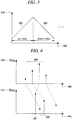
- FIG. 3 illustrates an example of a frequency of a radar sensor in a vehicle radar system according to an embodiment of the present disclosure.
- FIG. 3 shows a frequency (f) 310 of a transmission electromagnetic wave transmitted using a radar sensor of a slow chirp frequency modulation continuous wave (FMCW) depending on time (t) 300.
- the frequency 310 can be formed by an up-chirp 320 and a down-chirp 330.
- FIG. 4 illustrates an example of a frequency peak extracted by a vehicle radar system according to an embodiment of the present disclosure.
- a frequency peak 430 depending on a magnitude 410 of a frequency 400 of a reception electromagnetic wave illustrated in FIG. 4 can be extracted according to the up-chirp 320 and the down-chirp 330 of the frequency 310 of the transmission electromagnetic wave illustrated in FIG. 3 .
- the radar system of the present disclosure can receive reception electromagnetic waves including peaks of respective unpaired frequencies, analyze the reception electromagnetic waves and extract and pair the frequencies corresponding to the up-chirp and the down-chirp, respectively.
- the frequencies corresponding to the up-chirp and the down-chirp can be graphed as shown in FIG. 4 .
- the top graph of FIG. 4 is a graph of the peaks of the respective frequencies in the up-chirp
- the bottom graph is a graph of the peaks of the respective frequencies in the down-chirp.
- the same frequencies 432 may be extracted in the up-chirp and the down-chirp, respectively.
- a frequency 431 may be shifted in opposite directions by the magnitude of the speed.
- the radar sensor of the present disclosure is combined with the calculation module as described above in addition to the GPS sensor in order to increase the reliability in safety.
- the radar sensor may detect a relative speed with respect to an object when the host vehicle moves.
- the calculation module may calculate the speed of each object by adding the speed of the vehicle and relative speeds with respect to the respective objects detected by the radar sensor.
- the speed of the host vehicle is first estimated by using objects detected by the radar sensor and then relative speeds with respect to the respective objects are added to the estimated speed of the host vehicle, and, thus, the speed of each object can be calculated.
- TTC time-to-collision
- R and V values at that moment are assumed as fixed values (R and V values are assumed as fixed values within a cycle time because the cycle time is fast).
- the risk at that moment can be determined by the TTC.
- the TTC may be calculated for each cycle time (update time) to determine the risk at the moment, and a warning of the risk of collision may be issued depending on the TTC.
- the vehicle radar system including the radar sensor combined with the calculation module may be linked to a user device, such as a smartphone of the driver, or a vehicle navigation device to notify the driver of a danger detected by the radar.
- a user device such as a smartphone of the driver
- a vehicle navigation device to notify the driver of a danger detected by the radar.
- the application installed on a smartphone or tablet device
- the application enables the smartphone or tablet device to communicate with the calculation module of the radar sensor through near-field communication, and when a TTC with an object appearing ahead reaches a predetermined threshold value, an alarm is issued.
- the alarm may be implemented as a voice message or a warning sound and designed to sound more frequently or louder as a threshold time decreases.
- a danger sign may be displayed on a screen of the user device and accumulated as road-related information even though it has a lower efficiency than a voice alarm.
- the navigation device may be configured to issue a warning sound or a warning message.
- the warning sound or the warning message may also be designed to sound more frequently or louder as the collision threshold time decreases.
- a map including driving roads is displayed on the navigation device
- position information of an object detected by the radar sensor can be displayed on the navigation map.
- a GPS module needs to be installed to obtain the position information of the object from the radar sensor and display the position information of the object on the navigation map.
- the radar sensor may be installed in a conventional black box. Accordingly, the present disclosure can provide a vehicle radar system in which the black box and the radar sensor are integrated. A camera module, the radar sensor and the calculation module (including the communication module) are combined and installed where the black box has been installed, and, thus, a danger detection and a warning operation can be performed along with front image recording.
- the radar sensor can operate in two ways. For example, if a single processor (e.g., MCU, DSP, etc.) is used, each of the radar and the camera (black box) may be controlled and scheduled. For another example, if processors for the radar sensor and the black box, respectively, are used, the radar sensor and the black box may operate in a master-slave mode and scheduling is managed by the master.
- a single processor e.g., MCU, DSP, etc.
- processors for the radar sensor and the black box respectively, the radar sensor and the black box may operate in a master-slave mode and scheduling is managed by the master.
- the position of an antenna unit of the radar and the position of a module of the camera do not overlap each other. Also, the position of the radar needs to be considered to suppress beam distortion depending on the field-of-view (FOV) of the radar antenna. Further, if the radar is integrated with the black box, the FOV, lens position and shape of the camera need to be also considered.
- FOV field-of-view
- threshold time information on a collision risk time of the vehicle may be transmitted to an imaging module of the black box to record a dangerous situation. This is particularly useful when the black box does not perform recording all the time, and it is possible to obtain an effect of displaying a dangerous situation on the screen even when the black box performs recording all the time.
- the black box may be designed to perform high-resolution recording at that moment.
- the vehicle radar system may determine this situation as a dangerous situation and to be recorded through the black box.
- the vehicle radar system may estimate the moving path of each vehicle not only in front of the host vehicle but also changing its driving direction at an intersection or the like, and, thus, a collision warning can be issued in a dangerous situation (for example, a collision is expected) and the dangerous situation can be recorded through the black box.
- a recording command linked to the black box as described above may be usefully applied. That is, the black box transmits threshold time information on a collision risk time of the vehicle to the imaging module of the black box by communicating with the communication module through near-field communication in order for the imaging module to record a dangerous situation.
- the dangerous situation to be recorded through the black box as described above may include, for example, when a relative speed suddenly changes (for example, a sudden stop of the host vehicle or a sudden stop of another vehicle), the distance between the other vehicles suddenly changes (for example, a third vehicle cuts into the lane), steering of the host vehicle suddenly changes, the number of surrounding objects detected within a specific distance is equal to or more than a predetermined number, and a movement of one of objects detected around the host vehicle is abnormal (for example, an object from the opposing lane crosses the median and an object that abruptly moves in a lateral direction from a lane far from the host vehicle's lane is detected).
- a relative speed suddenly changes for example, a sudden stop of the host vehicle or a sudden stop of another vehicle
- the distance between the other vehicles suddenly changes for example, a third vehicle cuts into the lane
- steering of the host vehicle suddenly changes
- the number of surrounding objects detected within a specific distance is equal to or more than a predetermined number
- the radar sensor may be linked to the smartphone, the tablet computer or the navigation device through near-field communication such as Bluetooth, NFC and ZigBee.
- radar sensors may be further installed on both ends, respectively, of the rear of the vehicle in addition to the front of the vehicle and may issue a warning signal in case of a lane change.
- FIG. 1 shows the configuration in which a total of three radar sensors with a field-of-view (FOV) ranging from about -10° to about 10° are installed on the front of the vehicle and on the both ends, respectively, of the rear of the vehicle to detect a danger ahead and secure safety during a lane change. If an object is detected within a predetermined threshold distance during a lane change, the user device (a smartphone, a tablet computer and a navigation device) also issues a warning alarm.
- This configuration can be implemented by using near-field communication and installing an application or providing a program module in the navigation device.
- FIG. 2 shows that both a front radar sensor and a rear radar sensor are installed in the center of the vehicle.
- a radar sensor with a wider FOV is selected and installed as the rear radar sensor.
- a radar sensor with an FOV ranging from about -60° to about 60° in a short distance ranging from 60 m to 80 m is selected and installed on the rear of the vehicle.
- the above-described numerical ranges are merely preferred examples and can be somewhat changed.
- a method of warning may include issuing a warning sound, issuing a voice warning or image warning through the user application, or issuing a warning signal on the map screen of the navigation device in conjunction with the navigation device.
- the warning may be made by displaying the speed of the host vehicle or the distance to an object on the side of or behind the host vehicle on the screen of the user device or the map screen of the navigation device and/or telling the speed of the host vehicle or the distance to an object on the side of or behind the host vehicle via voice message.
- the user device may receive map information from the navigation device by exchanging information with a navigation application, determine whether an oncoming object exists in the host vehicle's lane by calculating the curvature of a road ahead, and display it on the screen of the user device or notify it by voice.
- the warning alarm may also be implemented as a flashing signal by installing a separate LED in the vehicle in addition to the sound message and the screen display.
- a radar sensor may be further installed on the rear of the vehicle in addition to the front of the vehicle to detect an object behind or on the side of the vehicle during a lane change, and when the radar sensor determines that a collision with the object is likely to occur within a predetermined threshold time, the user device may issue a warning signal.
- a method of warning may include issuing a warning sound, issuing a voice warning or image warning through the user application, or issuing a warning signal on the map screen of the navigation device in conjunction with the navigation device.
- the warning may be made by displaying the speed of the host vehicle or the distance to an object on the side of or behind the host vehicle on the screen of the user device or the map screen of the navigation device.
- a radar sensor for near-field detection may be provided inside the vehicle to detect the driver's condition.
- the driver's condition may include vital information such as breathing, heart rate and the like.
- the vehicle radar system may issue a warning via light, sound, vibration, and the like through the user device, the navigation device, and the like.
- the vehicle radar system may issue a warning or may alert the driver by using vibration, microcurrent, and the like in conjunction with a wearable device.
- the vehicle radar system may collect driver monitoring information from a server in conjunction with the smartphone, and when a predetermined amount of information is collected, the vehicle radar system may analyze the driver's biosignal pattern by analyzing the data to issue a prior warning for safe driving or alert the driver.
- the vehicle radar system may guide the driver to a suitable path for the driver's pattern in conjunction with a navigator in the smart phone and may also guide the driver to an appropriate time for rest.
- the vehicle radar system may sense not only the driver's seat but also the passenger seat and warn the passengers to fasten their seat belts.
- a radar may be provided within each of the driver's seat and the passenger seat to sense whether the passengers fasten their seat belts and issue a warning thereof.
- the vehicle radar system may monitor the vitals of the passengers in the driver's seat and the passenger seat to automatically make an emergency call when an abnormality occurs.
- a vehicle radar system that enables safe driving of a vehicle can be implemented.
Landscapes
- Engineering & Computer Science (AREA)
- Radar, Positioning & Navigation (AREA)
- Remote Sensing (AREA)
- Physics & Mathematics (AREA)
- Mechanical Engineering (AREA)
- Automation & Control Theory (AREA)
- Transportation (AREA)
- General Physics & Mathematics (AREA)
- Computer Networks & Wireless Communication (AREA)
- Electromagnetism (AREA)
- Human Computer Interaction (AREA)
- Mathematical Physics (AREA)
- Multimedia (AREA)
- Signal Processing (AREA)
- Traffic Control Systems (AREA)
- Time Recorders, Dirve Recorders, Access Control (AREA)
- Radar Systems Or Details Thereof (AREA)
Abstract
Description
- The present disclosure relates to a vehicle radar system for safe vehicle driving.
- When a vehicle is driven in heavy fog or at night under street lights, the vehicle cannot detect a suddenly oncoming object, which is a great threat to safe driving. This problem can be largely solved by installing a radar in the vehicle. This is because the radar can transmit and receive electromagnetic waves to detect all objects appearing hundreds of meters away from the vehicle, detect a relative speed between a moving vehicle and an object, and detect an object on a road even in fog or heavy rain. Such a radar system showing a strong resistance to environmental influences is installed as an option in an expensive vehicle in a manufacturing process of the vehicle and is operated to enable autonomous driving in conjunction with driving of the accelerator and the brake of the engine. However, a normal vehicle is not equipped with such a safety device and thus is not free from safety threats during driving.
- Meanwhile, recently, radar devices have become cheaper and applied to various security systems. Therefore, it is possible to pursue driving safety by installing a low-priced radar device in a normal vehicle.
- Utility Model Registration No.
20-0469656 - In view of the foregoing, the present disclosure provides a vehicle radar system capable of detecting the appearance of dangerous objects with higher reliability.
- Further, the present disclosure provides a vehicle radar system that can provide both safety and convenience of a driver by combining a radar sensor with a black box or a navigation device which is almost a necessity for vehicles.
- An aspect of the present disclosure provides a vehicle radar system in which a radar sensor is installed in a vehicle to calculate the speed of the host vehicle during driving, detect an object appearing ahead of the vehicle, calculate a relative speed between the host vehicle and the object, link the radar sensor to a user device, such as a smartphone of the driver, or a navigation device through near-field communication and issue a warning through the user device or the navigation device depending on the distance to the appearing object.
- In the above description, the radar sensor calculates the speed of the host vehicle by determining surrounding stationary objects or analyzing a spectrum of received signals and calculates the relative speed between the object and the host vehicle depending on the real-time measured position of the appearing object.
- In the above description, the radar sensor is linked to a smartphone, a tablet computer or a navigation device through near-field communication such as Bluetooth, NFC and ZigBee, and issues a warning sound and/or a warning image depending on a time-to-collision based on the distance and/or relative speed between the object and the host vehicle.
- Further, the present disclosure can provide the radar sensor as a black box-integrated danger detection system by integrating the radar sensor in a black box.
- Furthermore, in the present disclosure, when the radar sensor is linked to the navigation device, the position of the object detected by the radar sensor may be superimposed and displayed on a map displayed by the navigation device.
- Moreover, in the present disclosure, an application is installed on the user device of the driver in order for the radar sensor to issue a warning signal when detecting an object.
- Besides, in the present disclosure, radar sensors may be further installed on both ends, respectively, of the rear of the vehicle in addition to the front of the vehicle and may issue a warning signal in case of a lane change.
- According to the present disclosure, a radar sensor is installed in a normal vehicle and can detect the appearance of an object ahead of the vehicle through near-field communication between a smartphone or a navigation device of the driver without using GPS and issue a warning. Therefore, it is possible to protect the safety of the driver with high reliability.
- In other words, according to the present disclosure, the radar itself calculates a relative speed between the object and the host vehicle without using the GPS, determines a threshold time based on a collision time and issues a warning. Therefore, the driver can receive a detection result and a warning of the appearance of a dangerous object from the radar sensor even when driving in a tunnel where the GPS is disconnected or not available.
- Further, according to the present disclosure, if the radar sensor is linked to the navigation device, a detected position of the appearing object is displayed on a map screen of the navigation device. Therefore, it is possible to obtain more convenient road information.
- Furthermore, according to the present disclosure, the radar sensor is integrated with a black box since the black box is installed at a position where the best field-of-view of the vehicle can be obtained, and, thus, the radar sensor can be installed by installing the black box. Therefore, it is easy to install the radar sensor. Also, it is possible to avoid positional interference between the black box and the radar sensor.
- Moreover, according to the present disclosure, a radar sensor with a wider viewing angle is installed on the rear of the vehicle. Therefore, the driver can receive a warning signal when changing a lane and thus can change a lane more safely.
-
-
FIG. 1 is a schematic diagram for explaining an object detection by a vehicle radar system according to the present disclosure. -
FIG. 2 is a schematic diagram illustrating a wide detection angle of a radar sensor installed on the rear of a vehicle according to a modified example ofFIG. 1 . -
FIG. 3 illustrates an example of a frequency of a radar sensor in a vehicle radar system according to an embodiment of the present disclosure. -
FIG. 4 illustrates an example of a frequency peak extracted by a vehicle radar system according to an embodiment of the present disclosure. - Hereafter, embodiments of the present disclosure will be described in detail with reference to the accompanying drawings.
-
FIG. 1 illustrates an installation example of a vehicle radar sensor system according to the present disclosure. - A radar sensor that is not affected by environmental influences, such as fog, rain and strong winds, can detect an object appearing 150 to 200 meters ahead with high reliability during driving. Further, if a calculation module is provided in the radar sensor, the driving speed of the host vehicle can be estimated by receiving electromagnetic waves transmitted from a radar to surrounding stationary objects and analyzing a spectrum.
- Hereinafter, a process of estimating the driving speed of the host vehicle will be described with reference to
FIG. 3 and FIG. 4 . -
FIG. 3 illustrates an example of a frequency of a radar sensor in a vehicle radar system according to an embodiment of the present disclosure.FIG. 3 shows a frequency (f) 310 of a transmission electromagnetic wave transmitted using a radar sensor of a slow chirp frequency modulation continuous wave (FMCW) depending on time (t) 300. Thefrequency 310 can be formed by an up-chirp 320 and a down-chirp 330. -
FIG. 4 illustrates an example of a frequency peak extracted by a vehicle radar system according to an embodiment of the present disclosure. Referring toFIG. 3 and FIG. 4 , afrequency peak 430 depending on amagnitude 410 of afrequency 400 of a reception electromagnetic wave illustrated inFIG. 4 can be extracted according to the up-chirp 320 and the down-chirp 330 of thefrequency 310 of the transmission electromagnetic wave illustrated inFIG. 3 . - The radar system of the present disclosure can receive reception electromagnetic waves including peaks of respective unpaired frequencies, analyze the reception electromagnetic waves and extract and pair the frequencies corresponding to the up-chirp and the down-chirp, respectively. According to the pairing result, the frequencies corresponding to the up-chirp and the down-chirp can be graphed as shown in
FIG. 4 . For example, the top graph ofFIG. 4 is a graph of the peaks of the respective frequencies in the up-chirp, and the bottom graph is a graph of the peaks of the respective frequencies in the down-chirp. Through the pairing process, the peaks of the respective frequencies in the up-chirp and the peaks of the respective frequencies in the down-chirp can be extracted and paired as indicated by the dotted line. - For example, as for a stationary object, when the vehicle is stationary, the
same frequencies 432 may be extracted in the up-chirp and the down-chirp, respectively. However, when the vehicle moves, afrequency 431 may be shifted in opposite directions by the magnitude of the speed. As such, when the vehicle is stationary, it is easy to pair the frequencies in the up-chirp and the down-chirp, respectively, but in a real situation where the vehicle moves, there are many frequency peaks and it is not easy to pair the peaks in the up-chirp and the down-chirp, respectively. - Therefore, by analyzing an interval difference between frequency peaks in the process of pairing the peaks in the up-chirp and the down-chirp, it is possible to previously extract the
frequency peak 432 corresponding to the stationary object and thus possible to estimate the speed of the host vehicle. - Referring to
FIG. 1 again, it is possible to calculate a relative speed and a time-to-collision, which is the time left until a collision occurs, by analyzing a frequency of an electromagnetic wave transmitted by the vehicle radar system to the object appearing ahead and then reflected and received from the object. If the radar sensor is combined with a GPS sensor, it is easy to calculate the speed of the host vehicle and a relative speed of the host vehicle and the object and it is easy to link the sensor to a smartphone. However, in consideration of the disadvantages of the GPS such as disconnection and non-availability in a tunnel, the radar sensor of the present disclosure is combined with the calculation module as described above in addition to the GPS sensor in order to increase the reliability in safety. - Hereinafter, a process of calculating the time-to-collision by calculating a relative speed with respect to an object will be described.
- The radar sensor may detect a relative speed with respect to an object when the host vehicle moves. For example, when a communication module receives vehicle speed information through communication with the vehicle, the calculation module may calculate the speed of each object by adding the speed of the vehicle and relative speeds with respect to the respective objects detected by the radar sensor. For another example, when the communication module cannot receive vehicle speed information through communication with the vehicle, the speed of the host vehicle is first estimated by using objects detected by the radar sensor and then relative speeds with respect to the respective objects are added to the estimated speed of the host vehicle, and, thus, the speed of each object can be calculated.
- The time-to-collision can be derived based on T = R (distance between the host vehicle and another vehicle)/ V (relative speed between the host vehicle and another vehicle). For example, the time-to-collision (TTC) is derived from the distance and relative speed between the host vehicle and another vehicle in a collision risk situation, and R and V values at that moment are assumed as fixed values (R and V values are assumed as fixed values within a cycle time because the cycle time is fast). Thus, the risk at that moment can be determined by the TTC. Herein, the TTC may be calculated for each cycle time (update time) to determine the risk at the moment, and a warning of the risk of collision may be issued depending on the TTC.
- According to the present disclosure, the vehicle radar system including the radar sensor combined with the calculation module may be linked to a user device, such as a smartphone of the driver, or a vehicle navigation device to notify the driver of a danger detected by the radar. When an application installed on a smartphone or tablet device is executed, the application enables the smartphone or tablet device to communicate with the calculation module of the radar sensor through near-field communication, and when a TTC with an object appearing ahead reaches a predetermined threshold value, an alarm is issued. The alarm may be implemented as a voice message or a warning sound and designed to sound more frequently or louder as a threshold time decreases. A danger sign may be displayed on a screen of the user device and accumulated as road-related information even though it has a lower efficiency than a voice alarm.
- If the navigation device is linked to the calculation mode of the radar sensor, the navigation device may be configured to issue a warning sound or a warning message. In this case, the warning sound or the warning message may also be designed to sound more frequently or louder as the collision threshold time decreases.
- Further, since a map including driving roads is displayed on the navigation device, position information of an object detected by the radar sensor can be displayed on the navigation map. In this case, a GPS module needs to be installed to obtain the position information of the object from the radar sensor and display the position information of the object on the navigation map.
- Meanwhile, the radar sensor may be installed in a conventional black box. Accordingly, the present disclosure can provide a vehicle radar system in which the black box and the radar sensor are integrated. A camera module, the radar sensor and the calculation module (including the communication module) are combined and installed where the black box has been installed, and, thus, a danger detection and a warning operation can be performed along with front image recording.
- If the radar sensor is integrated with the black box, it can operate in two ways. For example, if a single processor (e.g., MCU, DSP, etc.) is used, each of the radar and the camera (black box) may be controlled and scheduled. For another example, if processors for the radar sensor and the black box, respectively, are used, the radar sensor and the black box may operate in a master-slave mode and scheduling is managed by the master.
- Here, if the radar is integrated with the black box, the position of an antenna unit of the radar and the position of a module of the camera do not overlap each other. Also, the position of the radar needs to be considered to suppress beam distortion depending on the field-of-view (FOV) of the radar antenna. Further, if the radar is integrated with the black box, the FOV, lens position and shape of the camera need to be also considered.
- Furthermore, as a result of the radar detection, threshold time information on a collision risk time of the vehicle may be transmitted to an imaging module of the black box to record a dangerous situation. This is particularly useful when the black box does not perform recording all the time, and it is possible to obtain an effect of displaying a dangerous situation on the screen even when the black box performs recording all the time. In some cases, the black box may be designed to perform high-resolution recording at that moment.
- For example, when a TTC between the vehicle and an object is equal to or less than a predetermined threshold value, the vehicle radar system may determine this situation as a dangerous situation and to be recorded through the black box. Here, the vehicle radar system may estimate the moving path of each vehicle not only in front of the host vehicle but also changing its driving direction at an intersection or the like, and, thus, a collision warning can be issued in a dangerous situation (for example, a collision is expected) and the dangerous situation can be recorded through the black box. Even if the black box is not integrated with the radar, a recording command linked to the black box as described above may be usefully applied. That is, the black box transmits threshold time information on a collision risk time of the vehicle to the imaging module of the black box by communicating with the communication module through near-field communication in order for the imaging module to record a dangerous situation.
- The dangerous situation to be recorded through the black box as described above may include, for example, when a relative speed suddenly changes (for example, a sudden stop of the host vehicle or a sudden stop of another vehicle), the distance between the other vehicles suddenly changes (for example, a third vehicle cuts into the lane), steering of the host vehicle suddenly changes, the number of surrounding objects detected within a specific distance is equal to or more than a predetermined number, and a movement of one of objects detected around the host vehicle is abnormal (for example, an object from the opposing lane crosses the median and an object that abruptly moves in a lateral direction from a lane far from the host vehicle's lane is detected).
- In the above description, the radar sensor may be linked to the smartphone, the tablet computer or the navigation device through near-field communication such as Bluetooth, NFC and ZigBee.
- Further, according to the present disclosure, radar sensors may be further installed on both ends, respectively, of the rear of the vehicle in addition to the front of the vehicle and may issue a warning signal in case of a lane change.
FIG. 1 shows the configuration in which a total of three radar sensors with a field-of-view (FOV) ranging from about -10° to about 10° are installed on the front of the vehicle and on the both ends, respectively, of the rear of the vehicle to detect a danger ahead and secure safety during a lane change. If an object is detected within a predetermined threshold distance during a lane change, the user device (a smartphone, a tablet computer and a navigation device) also issues a warning alarm. This configuration can be implemented by using near-field communication and installing an application or providing a program module in the navigation device. -
FIG. 2 shows that both a front radar sensor and a rear radar sensor are installed in the center of the vehicle. A radar sensor with a wider FOV is selected and installed as the rear radar sensor. A radar sensor with an FOV ranging from about -60° to about 60° in a short distance ranging from 60 m to 80 m is selected and installed on the rear of the vehicle. The above-described numerical ranges are merely preferred examples and can be somewhat changed. - In the above description, a method of warning may include issuing a warning sound, issuing a voice warning or image warning through the user application, or issuing a warning signal on the map screen of the navigation device in conjunction with the navigation device. The warning may be made by displaying the speed of the host vehicle or the distance to an object on the side of or behind the host vehicle on the screen of the user device or the map screen of the navigation device and/or telling the speed of the host vehicle or the distance to an object on the side of or behind the host vehicle via voice message.
- Further, the user device may receive map information from the navigation device by exchanging information with a navigation application, determine whether an oncoming object exists in the host vehicle's lane by calculating the curvature of a road ahead, and display it on the screen of the user device or notify it by voice.
- Meanwhile, in
FIG. 1 and FIG. 2 , the warning alarm may also be implemented as a flashing signal by installing a separate LED in the vehicle in addition to the sound message and the screen display. - Also, a radar sensor may be further installed on the rear of the vehicle in addition to the front of the vehicle to detect an object behind or on the side of the vehicle during a lane change, and when the radar sensor determines that a collision with the object is likely to occur within a predetermined threshold time, the user device may issue a warning signal.
- Further, a method of warning may include issuing a warning sound, issuing a voice warning or image warning through the user application, or issuing a warning signal on the map screen of the navigation device in conjunction with the navigation device. The warning may be made by displaying the speed of the host vehicle or the distance to an object on the side of or behind the host vehicle on the screen of the user device or the map screen of the navigation device. According to another embodiment of the present disclosure, a radar sensor for near-field detection may be provided inside the vehicle to detect the driver's condition. The driver's condition may include vital information such as breathing, heart rate and the like.
- For example, if the vehicle radar system estimates that the driver is dozing off while driving based on the detected driver's condition, it may issue a warning via light, sound, vibration, and the like through the user device, the navigation device, and the like. Alternatively, the vehicle radar system may issue a warning or may alert the driver by using vibration, microcurrent, and the like in conjunction with a wearable device.
- For another example, the vehicle radar system may collect driver monitoring information from a server in conjunction with the smartphone, and when a predetermined amount of information is collected, the vehicle radar system may analyze the driver's biosignal pattern by analyzing the data to issue a prior warning for safe driving or alert the driver. Alternatively, the vehicle radar system may guide the driver to a suitable path for the driver's pattern in conjunction with a navigator in the smart phone and may also guide the driver to an appropriate time for rest.
- For yet another example, the vehicle radar system may sense not only the driver's seat but also the passenger seat and warn the passengers to fasten their seat belts. For example, a radar may be provided within each of the driver's seat and the passenger seat to sense whether the passengers fasten their seat belts and issue a warning thereof.
- For still another example, the vehicle radar system may monitor the vitals of the passengers in the driver's seat and the passenger seat to automatically make an emergency call when an abnormality occurs.
- As described above, a vehicle radar system that enables safe driving of a vehicle can be implemented.
- The scope of rights of the present disclosure is not limited to the embodiments described above, but is defined by the claims, and it is obvious to a person with ordinary skill in the art that various modifications and changes can be made within the scope of the claims.
Claims (11)
- A vehicle radar system, comprising:a radar sensor installed in a vehicle;a calculation module configured to analyze a transmission electromagnetic wave and a reception electromagnetic wave of the radar sensor; anda communication module configured to communicate a result of calculation from the calculation module with a user device within the vehicle,wherein the calculation module calculates a time-to-collision between the vehicle and an object appearing ahead of the vehicle by analyzing an electromagnetic transmission/reception spectrum of the radar sensor, andwhen the time-to-collision reaches a predetermined threshold time, the user device issues a warning.
- The vehicle radar system of Claim 1,
wherein the user device includes a smartphone, a tablet computer, a black box or a navigation device, and
the communication module performs communication through near-field communication including Bluetooth, NFC or ZigBee, and
the warning includes the issuance of a warning sound, the flashing of a warning light or the display of a warning image. - The vehicle radar system of Claim 1,
wherein the vehicle radar system is integrated with a black box into a black box-integrated system. - The vehicle radar system of Claim 3,
wherein the communication module transmits, to an imaging module of the black box, a radar detection result and threshold time information on a collision risk time of the vehicle, and
the black box records a dangerous situation. - The vehicle radar system of Claim 4,
wherein if the user device is a black box, the communication module communicates with the black box through near-field communication and transmits, to an imaging module of the black box, threshold time information on a collision risk time of the vehicle, and
the black box records a dangerous situation. - The vehicle radar system of Claim 1,
wherein the calculation module further includes a GPS module, and
the communication module is linked to a navigation device through near-field communication, and
the position of the object detected by the radar sensor is superimposed and displayed on a map displayed by the navigation device. - The vehicle radar system of Claim 1,
wherein the user device issues a warning signal through an application installed on the user device. - The vehicle radar system of Claim 6,
wherein the communication module transmits, to an application installed on the navigation device, information about a warning signal indicating that threshold time has been reached as detected by the radar sensor, and
the warning signal is issued through the application installed on the navigation device. - The vehicle radar system of Claim 8,
wherein the user device receives map information from the navigation device by exchanging information with the application installed on the navigation device and determines whether an oncoming object exists in the host vehicle's lane by calculating the curvature of a road ahead. - The vehicle radar system of Claim 1,
wherein the radar sensor is further installed on the rear of the vehicle, and
the radar sensor detects an object behind or on the side of the vehicle during a lane change of the vehicle, and
when the calculation module determines that a collision with the object behind or on the side of the vehicle is likely to occur within a predetermined threshold time, the user device issues a warning signal. - The vehicle radar system of Claim 10,
wherein a method of warning includes issuing a warning sound, issuing a voice warning or image warning through an application installed on the user device, or issuing a warning signal on a map screen of the navigation device in conjunction with the navigation device, and the warning is made by displaying the speed of the vehicle or the distance to the object behind or on the side of the vehicle on a screen of the user device or the map screen of the navigation device.
Applications Claiming Priority (3)
| Application Number | Priority Date | Filing Date | Title |
|---|---|---|---|
| KR20180021661 | 2018-02-23 | ||
| KR1020190021399A KR20190101909A (en) | 2018-02-23 | 2019-02-22 | Viechle radar system for sensing danger |
| PCT/KR2019/002288 WO2019164372A1 (en) | 2018-02-23 | 2019-02-25 | Vehicle radar system for detecting dangerous goods |
Publications (2)
| Publication Number | Publication Date |
|---|---|
| EP3757612A1 true EP3757612A1 (en) | 2020-12-30 |
| EP3757612A4 EP3757612A4 (en) | 2021-11-17 |
Family
ID=67951464
Family Applications (1)
| Application Number | Title | Priority Date | Filing Date |
|---|---|---|---|
| EP19758003.8A Withdrawn EP3757612A4 (en) | 2018-02-23 | 2019-02-25 | Vehicle radar system for detecting dangerous goods |
Country Status (5)
| Country | Link |
|---|---|
| US (1) | US20200225343A1 (en) |
| EP (1) | EP3757612A4 (en) |
| JP (1) | JP2021520525A (en) |
| KR (1) | KR20190101909A (en) |
| CN (1) | CN111183367A (en) |
Families Citing this family (17)
| Publication number | Priority date | Publication date | Assignee | Title |
|---|---|---|---|---|
| KR102592826B1 (en) * | 2018-10-10 | 2023-10-23 | 현대자동차주식회사 | Apparatus and method for identificating short cut in vehicle and vehicle including the same |
| US11760371B2 (en) * | 2019-03-15 | 2023-09-19 | Honda Motor Co., Ltd | Vehicle communication device and non-transitory computer-readable recording medium storing program |
| WO2020188941A1 (en) * | 2019-03-15 | 2020-09-24 | 本田技研工業株式会社 | Vehicle communications device and program |
| KR20210041770A (en) | 2019-10-08 | 2021-04-16 | 주식회사 제이씨레이다 | Smart mobility detection radar |
| KR102860331B1 (en) * | 2019-11-20 | 2025-09-16 | 삼성전자주식회사 | Method and device to improve radar data using reference data |
| CN114730508A (en) * | 2019-11-22 | 2022-07-08 | 现代自动车株式会社 | System for recording event data of autonomous vehicle |
| US20230154484A1 (en) * | 2020-04-15 | 2023-05-18 | Nippon Telegraph And Telephone Corporation | Collection system, collection apparatus, method and program for the same |
| US11491976B2 (en) * | 2020-04-21 | 2022-11-08 | Baidu Usa Llc | Collision warning system for safety operators of autonomous vehicles |
| US12354420B2 (en) * | 2020-08-14 | 2025-07-08 | Kennith Burks | Systems and methods for an automobile status recorder |
| US11807257B2 (en) * | 2021-06-07 | 2023-11-07 | Toyota Connected North America, Inc. | Sensing interactions with unpermitted components within a vehicle |
| CN113208438B (en) * | 2021-06-24 | 2022-09-06 | 合肥美菱物联科技有限公司 | Early warning system and method for preventing kettle from toppling over in tea bar machine |
| CN113903142B (en) * | 2021-09-24 | 2022-12-06 | 广州智伴人工智能科技有限公司 | Method and system for monitoring outdoor state of child for intelligent accompanying robot |
| CN114137527A (en) * | 2021-11-30 | 2022-03-04 | 中汽创智科技有限公司 | Vehicle early warning method, device, equipment and storage medium |
| JP7487728B2 (en) * | 2021-12-10 | 2024-05-21 | トヨタ自動車株式会社 | Monitoring device, monitoring computer program, and monitoring method |
| CN114995640A (en) * | 2022-05-23 | 2022-09-02 | 浙江运动家体育发展有限公司 | Motion management method and system based on intelligent footpath |
| KR20240009692A (en) | 2022-07-14 | 2024-01-23 | 현대모비스 주식회사 | Signal simulator and method of signal simulation thereof |
| KR20240009691A (en) | 2022-07-14 | 2024-01-23 | 현대모비스 주식회사 | Signal simulator and method of signal simulation thereof |
Family Cites Families (17)
| Publication number | Priority date | Publication date | Assignee | Title |
|---|---|---|---|---|
| US7421321B2 (en) * | 1995-06-07 | 2008-09-02 | Automotive Technologies International, Inc. | System for obtaining vehicular information |
| US6592230B2 (en) * | 1997-10-16 | 2003-07-15 | Holland Hitch Company | Truck rearview mirror assembly having a display for displaying trailer coupling status information |
| US7796081B2 (en) * | 1997-10-22 | 2010-09-14 | Intelligent Technologies International, Inc. | Combined imaging and distance monitoring for vehicular applications |
| JP3658519B2 (en) * | 1999-06-28 | 2005-06-08 | 株式会社日立製作所 | Vehicle control system and vehicle control device |
| DE102009057191A1 (en) * | 2009-12-05 | 2011-06-09 | Valeo Schalter Und Sensoren Gmbh | Method for uniquely determining a distance and / or a relative speed of an object, driver assistance device and motor vehicle |
| CN201936364U (en) * | 2011-01-17 | 2011-08-17 | 杨静慧 | Driving recorder with speed measurement and video recording |
| CN102289952B (en) * | 2011-07-15 | 2014-11-26 | 黄克 | Vehicle anti-collision method based on satellite navigation system and navigation system and application thereof |
| KR101300534B1 (en) * | 2012-02-29 | 2013-09-02 | 주경희 | Method for displaying distance between cars and warning bumping danger of cars using wireless radar and apparatus using it |
| JP5939170B2 (en) * | 2013-01-17 | 2016-06-22 | 株式会社デンソー | Object approach notification system |
| JP6355234B2 (en) * | 2013-04-09 | 2018-07-11 | 株式会社ユピテル | Image recording apparatus, image recording system, and program |
| CN104369670B (en) * | 2013-08-15 | 2017-05-24 | 深圳市赛格导航科技股份有限公司 | Vehicle speed control method and system |
| KR101484618B1 (en) * | 2014-03-24 | 2015-01-21 | (주)디지탈엣지 | Management system and method of radar apparatus |
| KR20160091040A (en) * | 2015-01-23 | 2016-08-02 | 엘지전자 주식회사 | Vehicle and Control Method Thereof |
| JP6056069B2 (en) * | 2015-09-17 | 2017-01-11 | 株式会社ユピテル | Drive recorder body and equipment |
| JP6211043B2 (en) * | 2015-11-05 | 2017-10-11 | 三菱電機株式会社 | Vehicle collision prevention device |
| JP2017107475A (en) * | 2015-12-11 | 2017-06-15 | セルスター工業株式会社 | On-vehicle system and drive recorder |
| JP6132327B1 (en) * | 2016-09-12 | 2017-05-24 | Kenpal株式会社 | Operation management support system, operation management method, server device, and program |
-
2019
- 2019-02-22 KR KR1020190021399A patent/KR20190101909A/en not_active Ceased
- 2019-02-25 EP EP19758003.8A patent/EP3757612A4/en not_active Withdrawn
- 2019-02-25 CN CN201980004792.0A patent/CN111183367A/en active Pending
- 2019-02-25 JP JP2020518804A patent/JP2021520525A/en active Pending
-
2020
- 2020-03-26 US US16/830,786 patent/US20200225343A1/en not_active Abandoned
Also Published As
| Publication number | Publication date |
|---|---|
| JP2021520525A (en) | 2021-08-19 |
| EP3757612A4 (en) | 2021-11-17 |
| US20200225343A1 (en) | 2020-07-16 |
| KR20190101909A (en) | 2019-09-02 |
| CN111183367A (en) | 2020-05-19 |
Similar Documents
| Publication | Publication Date | Title |
|---|---|---|
| US20200225343A1 (en) | Vehicle radar system for detecting dangerous goods | |
| US10127815B2 (en) | Method and device for setting up a movement model of a road user | |
| CN106683464B (en) | System and method for providing alerts to a vehicle based on vehicle dynamic inputs | |
| CN101625797B (en) | A kind of early warning method and early warning device when the car approaches at high speed | |
| US6442484B1 (en) | Method and apparatus for pre-crash threat assessment using spheroidal partitioning | |
| US10192443B2 (en) | Collision avoidance system and collision avoidance method | |
| US11091173B2 (en) | Driving safety enhancing system and method for making or enabling highly accurate judgment and providing advance early warning | |
| KR102150034B1 (en) | SAFE DRIVING SUPPORT SYSTEM BASED ON MOBILE IoT AGENT AND METHOD FOR PROCESSING THEREOF | |
| US20170287332A1 (en) | Method and device for monitoring a traffic space | |
| US20100198513A1 (en) | Combined Vehicle-to-Vehicle Communication and Object Detection Sensing | |
| US8791806B2 (en) | Real-time detection of hazardous driving | |
| CN104900052A (en) | Traffic monitoring system | |
| CN103909926A (en) | Vehicle lateral collision prevention method, device and system | |
| CN102616198A (en) | Active safety control method and device for automobile based on millimeter wave radar detection and image recognition | |
| US11999370B2 (en) | Automated vehicle system | |
| CN105334514A (en) | Tramcar radar video compound early warning crashproof system and method | |
| KR101079391B1 (en) | System and Method for Preventing Collision Using Through-Wall Measurements of Radar | |
| CN115482685A (en) | Vehicle early warning control method, system and vehicle | |
| CN109383371A (en) | A kind of ADAS product driveway deviation alarming system | |
| CN108831189A (en) | A kind of intelligent early-warning method based on millimetre-wave radar anticollision | |
| JP5354193B2 (en) | Vehicle driving support device | |
| WO2019164372A1 (en) | Vehicle radar system for detecting dangerous goods | |
| KR102730172B1 (en) | Radar System for Vehicle And Control Method Therefor | |
| US20240338950A1 (en) | Systems and methods for sensing environment around vehicles | |
| CN219790036U (en) | Visual buffer stop of many radars |
Legal Events
| Date | Code | Title | Description |
|---|---|---|---|
| STAA | Information on the status of an ep patent application or granted ep patent |
Free format text: STATUS: THE INTERNATIONAL PUBLICATION HAS BEEN MADE |
|
| PUAI | Public reference made under article 153(3) epc to a published international application that has entered the european phase |
Free format text: ORIGINAL CODE: 0009012 |
|
| STAA | Information on the status of an ep patent application or granted ep patent |
Free format text: STATUS: REQUEST FOR EXAMINATION WAS MADE |
|
| 17P | Request for examination filed |
Effective date: 20200803 |
|
| AK | Designated contracting states |
Kind code of ref document: A1 Designated state(s): AL AT BE BG CH CY CZ DE DK EE ES FI FR GB GR HR HU IE IS IT LI LT LU LV MC MK MT NL NO PL PT RO RS SE SI SK SM TR |
|
| AX | Request for extension of the european patent |
Extension state: BA ME |
|
| DAV | Request for validation of the european patent (deleted) | ||
| DAX | Request for extension of the european patent (deleted) | ||
| A4 | Supplementary search report drawn up and despatched |
Effective date: 20211019 |
|
| RIC1 | Information provided on ipc code assigned before grant |
Ipc: G01S 13/34 20060101ALI20211013BHEP Ipc: G01S 13/931 20200101ALI20211013BHEP Ipc: G01S 7/00 20060101ALI20211013BHEP Ipc: B60W 30/09 20120101ALI20211013BHEP Ipc: G07C 5/08 20060101ALI20211013BHEP Ipc: B60R 11/02 20060101ALI20211013BHEP Ipc: B60W 40/072 20120101ALI20211013BHEP Ipc: B60W 30/08 20120101ALI20211013BHEP Ipc: B60W 50/14 20200101ALI20211013BHEP Ipc: G01S 13/93 20200101AFI20211013BHEP |
|
| STAA | Information on the status of an ep patent application or granted ep patent |
Free format text: STATUS: THE APPLICATION IS DEEMED TO BE WITHDRAWN |
|
| 18D | Application deemed to be withdrawn |
Effective date: 20220519 |