EP3757601B1 - Verfahren und system zur kartographischen aufzeichnung einer physischen umgebung mit hilfe eines okkupationsrasters - Google Patents
Verfahren und system zur kartographischen aufzeichnung einer physischen umgebung mit hilfe eines okkupationsrasters Download PDFInfo
- Publication number
- EP3757601B1 EP3757601B1 EP20182586.6A EP20182586A EP3757601B1 EP 3757601 B1 EP3757601 B1 EP 3757601B1 EP 20182586 A EP20182586 A EP 20182586A EP 3757601 B1 EP3757601 B1 EP 3757601B1
- Authority
- EP
- European Patent Office
- Prior art keywords
- sensor
- segment
- probability
- occupancy
- coordinate system
- Prior art date
- Legal status (The legal status is an assumption and is not a legal conclusion. Google has not performed a legal analysis and makes no representation as to the accuracy of the status listed.)
- Active
Links
Images



Classifications
-
- B—PERFORMING OPERATIONS; TRANSPORTING
- B60—VEHICLES IN GENERAL
- B60W—CONJOINT CONTROL OF VEHICLE SUB-UNITS OF DIFFERENT TYPE OR DIFFERENT FUNCTION; CONTROL SYSTEMS SPECIALLY ADAPTED FOR HYBRID VEHICLES; ROAD VEHICLE DRIVE CONTROL SYSTEMS FOR PURPOSES NOT RELATED TO THE CONTROL OF A PARTICULAR SUB-UNIT
- B60W60/00—Drive control systems specially adapted for autonomous road vehicles
- B60W60/001—Planning or execution of driving tasks
- B60W60/0025—Planning or execution of driving tasks specially adapted for specific operations
-
- G—PHYSICS
- G01—MEASURING; TESTING
- G01S—RADIO DIRECTION-FINDING; RADIO NAVIGATION; DETERMINING DISTANCE OR VELOCITY BY USE OF RADIO WAVES; LOCATING OR PRESENCE-DETECTING BY USE OF THE REFLECTION OR RERADIATION OF RADIO WAVES; ANALOGOUS ARRANGEMENTS USING OTHER WAVES
- G01S7/00—Details of systems according to groups G01S13/00, G01S15/00, G01S17/00
- G01S7/48—Details of systems according to groups G01S13/00, G01S15/00, G01S17/00 of systems according to group G01S17/00
- G01S7/4808—Evaluating distance, position or velocity data
-
- G—PHYSICS
- G01—MEASURING; TESTING
- G01S—RADIO DIRECTION-FINDING; RADIO NAVIGATION; DETERMINING DISTANCE OR VELOCITY BY USE OF RADIO WAVES; LOCATING OR PRESENCE-DETECTING BY USE OF THE REFLECTION OR RERADIATION OF RADIO WAVES; ANALOGOUS ARRANGEMENTS USING OTHER WAVES
- G01S13/00—Systems using the reflection or reradiation of radio waves, e.g. radar systems; Analogous systems using reflection or reradiation of waves whose nature or wavelength is irrelevant or unspecified
- G01S13/88—Radar or analogous systems specially adapted for specific applications
- G01S13/93—Radar or analogous systems specially adapted for specific applications for anti-collision purposes
- G01S13/931—Radar or analogous systems specially adapted for specific applications for anti-collision purposes of land vehicles
-
- B—PERFORMING OPERATIONS; TRANSPORTING
- B60—VEHICLES IN GENERAL
- B60W—CONJOINT CONTROL OF VEHICLE SUB-UNITS OF DIFFERENT TYPE OR DIFFERENT FUNCTION; CONTROL SYSTEMS SPECIALLY ADAPTED FOR HYBRID VEHICLES; ROAD VEHICLE DRIVE CONTROL SYSTEMS FOR PURPOSES NOT RELATED TO THE CONTROL OF A PARTICULAR SUB-UNIT
- B60W30/00—Purposes of road vehicle drive control systems not related to the control of a particular sub-unit, e.g. of systems using conjoint control of vehicle sub-units
- B60W30/08—Active safety systems predicting or avoiding probable or impending collision or attempting to minimise its consequences
- B60W30/095—Predicting travel path or likelihood of collision
- B60W30/0956—Predicting travel path or likelihood of collision the prediction being responsive to traffic or environmental parameters
-
- G—PHYSICS
- G01—MEASURING; TESTING
- G01S—RADIO DIRECTION-FINDING; RADIO NAVIGATION; DETERMINING DISTANCE OR VELOCITY BY USE OF RADIO WAVES; LOCATING OR PRESENCE-DETECTING BY USE OF THE REFLECTION OR RERADIATION OF RADIO WAVES; ANALOGOUS ARRANGEMENTS USING OTHER WAVES
- G01S13/00—Systems using the reflection or reradiation of radio waves, e.g. radar systems; Analogous systems using reflection or reradiation of waves whose nature or wavelength is irrelevant or unspecified
- G01S13/02—Systems using reflection of radio waves, e.g. primary radar systems; Analogous systems
- G01S13/06—Systems determining position data of a target
- G01S13/08—Systems for measuring distance only
-
- G—PHYSICS
- G01—MEASURING; TESTING
- G01S—RADIO DIRECTION-FINDING; RADIO NAVIGATION; DETERMINING DISTANCE OR VELOCITY BY USE OF RADIO WAVES; LOCATING OR PRESENCE-DETECTING BY USE OF THE REFLECTION OR RERADIATION OF RADIO WAVES; ANALOGOUS ARRANGEMENTS USING OTHER WAVES
- G01S13/00—Systems using the reflection or reradiation of radio waves, e.g. radar systems; Analogous systems using reflection or reradiation of waves whose nature or wavelength is irrelevant or unspecified
- G01S13/86—Combinations of radar systems with non-radar systems, e.g. sonar, direction finder
- G01S13/865—Combination of radar systems with lidar systems
-
- G—PHYSICS
- G01—MEASURING; TESTING
- G01S—RADIO DIRECTION-FINDING; RADIO NAVIGATION; DETERMINING DISTANCE OR VELOCITY BY USE OF RADIO WAVES; LOCATING OR PRESENCE-DETECTING BY USE OF THE REFLECTION OR RERADIATION OF RADIO WAVES; ANALOGOUS ARRANGEMENTS USING OTHER WAVES
- G01S13/00—Systems using the reflection or reradiation of radio waves, e.g. radar systems; Analogous systems using reflection or reradiation of waves whose nature or wavelength is irrelevant or unspecified
- G01S13/88—Radar or analogous systems specially adapted for specific applications
- G01S13/89—Radar or analogous systems specially adapted for specific applications for mapping or imaging
-
- G—PHYSICS
- G01—MEASURING; TESTING
- G01S—RADIO DIRECTION-FINDING; RADIO NAVIGATION; DETERMINING DISTANCE OR VELOCITY BY USE OF RADIO WAVES; LOCATING OR PRESENCE-DETECTING BY USE OF THE REFLECTION OR RERADIATION OF RADIO WAVES; ANALOGOUS ARRANGEMENTS USING OTHER WAVES
- G01S17/00—Systems using the reflection or reradiation of electromagnetic waves other than radio waves, e.g. lidar systems
- G01S17/02—Systems using the reflection of electromagnetic waves other than radio waves
- G01S17/06—Systems determining position data of a target
- G01S17/08—Systems determining position data of a target for measuring distance only
-
- G—PHYSICS
- G01—MEASURING; TESTING
- G01S—RADIO DIRECTION-FINDING; RADIO NAVIGATION; DETERMINING DISTANCE OR VELOCITY BY USE OF RADIO WAVES; LOCATING OR PRESENCE-DETECTING BY USE OF THE REFLECTION OR RERADIATION OF RADIO WAVES; ANALOGOUS ARRANGEMENTS USING OTHER WAVES
- G01S17/00—Systems using the reflection or reradiation of electromagnetic waves other than radio waves, e.g. lidar systems
- G01S17/88—Lidar systems specially adapted for specific applications
- G01S17/89—Lidar systems specially adapted for specific applications for mapping or imaging
-
- G—PHYSICS
- G01—MEASURING; TESTING
- G01S—RADIO DIRECTION-FINDING; RADIO NAVIGATION; DETERMINING DISTANCE OR VELOCITY BY USE OF RADIO WAVES; LOCATING OR PRESENCE-DETECTING BY USE OF THE REFLECTION OR RERADIATION OF RADIO WAVES; ANALOGOUS ARRANGEMENTS USING OTHER WAVES
- G01S17/00—Systems using the reflection or reradiation of electromagnetic waves other than radio waves, e.g. lidar systems
- G01S17/88—Lidar systems specially adapted for specific applications
- G01S17/93—Lidar systems specially adapted for specific applications for anti-collision purposes
- G01S17/931—Lidar systems specially adapted for specific applications for anti-collision purposes of land vehicles
-
- G—PHYSICS
- G05—CONTROLLING; REGULATING
- G05D—SYSTEMS FOR CONTROLLING OR REGULATING NON-ELECTRIC VARIABLES
- G05D1/00—Control of position, course, altitude or attitude of land, water, air or space vehicles, e.g. using automatic pilots
- G05D1/02—Control of position or course in two dimensions
- G05D1/021—Control of position or course in two dimensions specially adapted to land vehicles
- G05D1/0231—Control of position or course in two dimensions specially adapted to land vehicles using optical position detecting means
- G05D1/0238—Control of position or course in two dimensions specially adapted to land vehicles using optical position detecting means using obstacle or wall sensors
- G05D1/024—Control of position or course in two dimensions specially adapted to land vehicles using optical position detecting means using obstacle or wall sensors in combination with a laser
-
- G—PHYSICS
- G05—CONTROLLING; REGULATING
- G05D—SYSTEMS FOR CONTROLLING OR REGULATING NON-ELECTRIC VARIABLES
- G05D1/00—Control of position, course, altitude or attitude of land, water, air or space vehicles, e.g. using automatic pilots
- G05D1/02—Control of position or course in two dimensions
- G05D1/021—Control of position or course in two dimensions specially adapted to land vehicles
- G05D1/0257—Control of position or course in two dimensions specially adapted to land vehicles using a radar
-
- G—PHYSICS
- G05—CONTROLLING; REGULATING
- G05D—SYSTEMS FOR CONTROLLING OR REGULATING NON-ELECTRIC VARIABLES
- G05D1/00—Control of position, course, altitude or attitude of land, water, air or space vehicles, e.g. using automatic pilots
- G05D1/02—Control of position or course in two dimensions
- G05D1/021—Control of position or course in two dimensions specially adapted to land vehicles
- G05D1/0268—Control of position or course in two dimensions specially adapted to land vehicles using internal positioning means
- G05D1/0274—Control of position or course in two dimensions specially adapted to land vehicles using internal positioning means using mapping information stored in a memory device
-
- G—PHYSICS
- G05—CONTROLLING; REGULATING
- G05D—SYSTEMS FOR CONTROLLING OR REGULATING NON-ELECTRIC VARIABLES
- G05D1/00—Control of position, course, altitude or attitude of land, water, air or space vehicles, e.g. using automatic pilots
- G05D1/20—Control system inputs
- G05D1/24—Arrangements for determining position or orientation
- G05D1/247—Arrangements for determining position or orientation using signals provided by artificial sources external to the vehicle, e.g. navigation beacons
-
- G—PHYSICS
- G06—COMPUTING OR CALCULATING; COUNTING
- G06F—ELECTRIC DIGITAL DATA PROCESSING
- G06F17/00—Digital computing or data processing equipment or methods, specially adapted for specific functions
- G06F17/10—Complex mathematical operations
- G06F17/11—Complex mathematical operations for solving equations, e.g. nonlinear equations, general mathematical optimization problems
- G06F17/13—Differential equations
-
- G—PHYSICS
- G06—COMPUTING OR CALCULATING; COUNTING
- G06F—ELECTRIC DIGITAL DATA PROCESSING
- G06F17/00—Digital computing or data processing equipment or methods, specially adapted for specific functions
- G06F17/10—Complex mathematical operations
- G06F17/18—Complex mathematical operations for evaluating statistical data, e.g. average values, frequency distributions, probability functions, regression analysis
-
- B—PERFORMING OPERATIONS; TRANSPORTING
- B60—VEHICLES IN GENERAL
- B60W—CONJOINT CONTROL OF VEHICLE SUB-UNITS OF DIFFERENT TYPE OR DIFFERENT FUNCTION; CONTROL SYSTEMS SPECIALLY ADAPTED FOR HYBRID VEHICLES; ROAD VEHICLE DRIVE CONTROL SYSTEMS FOR PURPOSES NOT RELATED TO THE CONTROL OF A PARTICULAR SUB-UNIT
- B60W2420/00—Indexing codes relating to the type of sensors based on the principle of their operation
- B60W2420/40—Photo, light or radio wave sensitive means, e.g. infrared sensors
- B60W2420/408—Radar; Laser, e.g. lidar
Definitions
- the present description relates to the generation of maps of physical environments around sensors, in particular in the field of motor vehicles, in particular that of motor vehicles that are autonomous and/or equipped with one or more advanced driver assistance systems.
- the present description refers more specifically to a simplified method and a corresponding system for mapping a physical environment around a sensor, as well as to a method of driving a motor vehicle equipped with the sensor and to the corresponding vehicle.
- ADAS Advanced Driver Assistance Systems
- lidars and/or radars a widely used approach consists of detecting objects or obstacles in the vehicle's environment, using one or more sensors, then transforming the raw data from the sensors into an occupancy grid containing cells associated with respective occupancy probabilities. The occupancy probability of each cell is calculated using an algorithm called the “Inverse Sensor Model” which converts sensed data and additional information into occupancy probabilities.
- the sensors used are distance estimation sensors, for example radars and/or lidars.
- the document US 2017/269201 A1 describes a method for estimating a surrounding environment from observation data obtained using sensing equipment.
- the present description aims to improve the situation, and in particular to simplify the establishment of a map of the environment around a sensor.
- the present description relates to a method as defined by claim 1.
- the method makes it possible to provide information on an object of the environment, such as an obstacle, in order to evaluate the situation around the sensor. This information can then be used to determine a driving space of a motor vehicle and to plan a route.
- the method makes it possible to reduce the complexity of the calculations for determining the occupancy probability values of the cells of the occupancy grid, in particular thanks to the fact that the distribution of the probable values is carried out according to a single dimension of the coordinate system of the sensor. This results in a reduced required computational effort.
- one of the two dimensions of the coordinate system of the sensor is chosen, for the implementation of said step of identifying a segment, as a function of characteristics of the sensor for estimating the distance relating to an uncertainty of measurement according to each of the two dimensions of the coordinate system of the sensor.
- the coordinate system of the sensor is a system of polar coordinates in which each point is represented by a distance and an azimuth, and, in the case where the measurement uncertainty of the sensor is considered to be negligible, because less than one predefined threshold, in the azimuth dimension, the segment representing an interval of distribution of probable values relating to the measured potential position is a segment of the straight line defined by the measured potential position and an origin of the coordinate system of the sensor, the middle of said segment corresponding to the measured potential position.
- the sensor coordinate system is a polar coordinate system in which each point is represented by a distance and an azimuth and, in the case where the measurement uncertainty of the sensor is considered negligible, because it is less than a threshold predefined, in the distance dimension, the segment representing a distribution interval of probable values relating to the measured potential position is an arc of a circle.
- the method comprises an approximation step during which said arc of a circle is approximated by a straight line segment perpendicular to the direction of a line defined by the measured potential position and a point of origin of the coordinate system of the sensor.
- an approximation further simplifies calculations for dealing with azimuth uncertainty by allowing simplified and accurate identification of potentially occupied cells.
- the approximate probability value assigned to said potentially occupied cell is the probability value given by the probability density function at the midpoint of the segment portion included in said potentially occupied cell.
- an additional simplification of the calculations is based on a substitution of the integration of the probability function over the distribution interval by an approximation of the integral to the area of a rectangle.
- the sensor can be a lidar, a radar, a camera or any other device capable of measuring data relating to the position of an object.
- the distance dimension is chosen for the implementation of said step of identifying a segment.
- the azimuth dimension is chosen for the implementation of said step of identifying a segment.
- a second aspect relates to a method for detecting an obstacle comprising the generation of a map of a physical environment by the implementation of the previously defined method and a step of detecting an obstacle in said environment on the basis of the map generated.
- a third aspect relates to a method for driving an autonomous motor vehicle or for assisting the driving of a motor vehicle equipped with at least one advanced driver assistance system, characterized in that it comprises an operation generating a map of a physical environment of the vehicle by implementing the method defined above.
- a fourth aspect concerns a system according to claim 11.
- a fifth aspect concerns a system for detecting an obstacle integrating the system for mapping a physical environment as previously defined and a module for detecting an obstacle in said environment on the basis of the generated cartography.
- a sixth aspect relates to a motor vehicle that is autonomous or equipped with at least one advanced driving assistance system, integrating a system, as previously defined, for mapping a physical environment of said vehicle by means of an occupancy grid containing a set of cells defined by respective occupancy probabilities.
- FIG. 1 represents a particular embodiment of a system 100 for mapping a physical environment by means of an occupancy grid 200 containing a set of cells g ij assigned respective occupancy probabilities.
- the picture 3 represents a two-dimensional (x,y) occupation grid 200 in a coordinate system of the grid 200, for example a Cartesian coordinate system.
- the occupancy grid 200 is used to tile or discretize a representation of the environment, in the form of a set of cells g ij arranged in rows and columns, as represented on the picture 3 .
- the grid 200 is made up of N L ⁇ N W cells g ij , of square shape and of the same size, forming a grid.
- Nw represents the number of cells g ij on the abscissa
- N L represents the number of cells g ij on the ordinate.
- the origin point O of the grid 200 coordinate system corresponds to the origin vertex of the grid 200 at the lower left on the picture 3 .
- the spatial resolution, denoted res, of the grid 200 corresponds to the dimension of one side of a cell g ij .
- a position on the grid 200 can be described in the Cartesian coordinate system of the grid by physical distances in abscissa x and ordinate y, for example expressed in meters.
- Each cell g ij occupies a given position in the grid 200, which is known and defined by an index i, here between 1 and N L , and an index j, here between 1 and Nw.
- the system 100 is for example integrated into a motor vehicle (not shown) and makes it possible to establish a map around the vehicle in the form of an occupancy grid 200, similar to that of the picture 3 , whose cells are associated with respective occupancy probabilities.
- occupancy probabilities are for example values between 0 and 1, the value "0" corresponding to an unoccupied cell and the value "1" corresponding to a cell definitely occupied (probability of occupancy of 100%, in other words equal to 1).
- the system 100 comprises a measuring device 10 for measuring a potential position ⁇ of an object (such as an obstacle), a module 20 for identifying a segment corresponding to a distribution interval of probable values (or probable positions ) of the measured potential position ⁇ , an evaluation module 30 grid cell occupancy probabilities 200 and a module 40 for generating an occupancy grid 200.
- a measuring device 10 for measuring a potential position ⁇ of an object (such as an obstacle)
- a module 20 for identifying a segment corresponding to a distribution interval of probable values (or probable positions ) of the measured potential position ⁇
- an evaluation module 30 grid cell occupancy probabilities 200
- a module 40 for generating an occupancy grid 200.
- the measuring device 10 comprises at least one distance estimation sensor 11 and a memory for storing the measured raw data.
- the sensor 11 is arranged to measure a position of an object (such as an obstacle) of the physical environment of the sensor 11 and supply, for the measured position, measured data comprising a first coordinate, according to a first dimension, and a second coordinate, along a second dimension, in a coordinate system of the sensor with at least two dimensions.
- the coordinate system of the sensor 11 is a polar coordinate system in which each point is represented by a distance r and an azimuth (angle) ⁇ with respect to a polar axis (equivalent to the abscissa axis x in coordinates Cartesian coordinates, in the 200 grid coordinate system).
- the sensor 11 measures and provides data of a detected position comprising a distance r and an azimuth ⁇ . The data thus measured are stored, at least temporarily, in the memory 12.
- the identification module 20 is intended to identify a segment S (or section of line), representing an interval of distribution of probable values relating to the measured potential position ⁇ , which extends along only one of the two dimensions of the system sensor coordinates.
- segment S extends either in distance (with a fixed azimuth) or in azimuth (with a fixed distance).
- the distribution interval represented graphically by the segment S, represents an uncertainty on the measured position ⁇ according to only one of the two dimensions of the coordinate system of the sensor 11, that is to say here either the uncertainty on the measured distance r, ie the uncertainty on the measured azimuth ⁇ .
- the treatment of the measurement uncertainty according to only one of the dimensions by neglecting the dimension in which the sensor 11 offers a high measurement precision, makes it possible to reduce in a consequent way the complexity of the calculations to determine the values of probability of occupancy grid cells, while allowing accurate calculations.
- the mapping system 100 can be integrated into a system 300 for detecting an obstacle comprising, in addition to the elements 10, 20, 30 and 40 of the system 100, a module 50 for detecting an obstacle using the cartography generated from the environment, ie the grid of cells g ij respectively associated with occupancy probabilities.
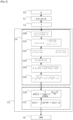
- the method first comprises a measurement step E0, here using the distance estimation sensor 11, of a potential position ⁇ of an object in the physical environment of the sensor.
- the sensor 11 is for example a radar or a lidar or any other sensor suitable for evaluating a distance between itself and an object or obstacle in the environment.
- the sensor 11 supplies, for the measured potential position ⁇ , a first coordinate, according to a first dimension, and a second coordinate, according to a second dimension, in a coordinate system with at least two dimensions. of the sensor 11.
- the coordinate system of the sensor 11 is a two-dimensional polar coordinate system in which each point is represented by a distance r and an azimuth ⁇ with respect to a polar axis (equivalent to the abscissa axis in Cartesian coordinates, in the coordinate system of the grid 200).
- Sensor 11 provides a distance coordinate ⁇ r and an azimuth coordinate ⁇ ⁇ for the point whose potential position ⁇ is measured by sensor 11.
- Step E1 the Cartesian coordinates ⁇ x and ⁇ y of the measured potential position ⁇ in the system of coordinates of the occupancy grid 200 are calculated, from the polar coordinates of distance ⁇ r and azimuth ⁇ ⁇ of the measured potential position ⁇ and the known position of the sensor 11 in the Cartesian coordinate system of the grid 200 (this position being defined by Cartesian coordinates in x and y of the sensor 11 in the coordinate system of the grid 200).
- Step E1 is implemented by a conversion unit 21 of the identification module 20.
- the method also comprises a step E2 of identifying a segment S representing a distribution interval of probable values relating to the measured potential position ⁇ .
- a calculation unit 22 of the identification module 20 determines a distribution interval of probable values relating to the measured potential position ⁇ .
- This distribution interval corresponds to a set of probable positions of the point whose potential position ⁇ has been measured by the sensor 11. Indeed, due to the characteristics of the sensor 11, in particular the measurement precision of the sensor 11 in distance and in azimuth, there is uncertainty in the values of the coordinates of the position measured by the sensor 11.
- the distribution interval can be represented by a segment S, as shown in the figure 4 And 5 . This segment extends along only one of the two dimensions of the coordinate system of the sensor 11.
- the segment S is defined either by a bounded interval of distances and a given azimuth ( figure 4 ), or by a bounded angular interval and a given distance ( figure 5 ). It can therefore be either a portion of a line ( figure 4 ), in the case of a segment extending only in the distance dimension r, i.e. an arc of a circle ( figure 5 ), in the case of a segment extending only in the angular dimension ⁇ .
- the probable values relating to the measured potential position ⁇ include a range of distances r associated with a fixed azimuth value.
- the distance in the middle of this range and the associated azimuth are the polar coordinates of the measured potential position ⁇ in the coordinate system of the sensor 11.
- the probable values relating to the measured potential position ⁇ comprise a range of angles ⁇ associated with a fixed distance value.
- the angle in the middle of this range and the associated distance are the polar coordinates of the measured potential position ⁇ in the coordinate system of sensor 11.
- the probable values relating to the measured potential position ⁇ are associated with probability values given by a probability density function ⁇ .
- the probability value of a point of the segment S represents the probability that the detection (that is to say the object detected by the sensor 11) is positioned at this point.
- the probability density function ⁇ can be represented graphically by a curve C FDP which associates probability values with each of the values of the distribution interval, represented graphically by the segment S.
- the curve C FDP associated with the segment S of the figure 4 is a Gaussian function.
- Curve C FDP has a peak which corresponds to the measured potential position ⁇ .
- the top of the curve C FDP is the image of the position measured ⁇ by the probability density function ⁇ .
- the curve C FDP is symmetrical with respect to a central axis passing through its vertex.
- the length of the segment S (in other words the width of the distribution interval) is chosen so that the sum of the probability values associated with each of the points of the segment (in other words the integral of the probability density function ⁇ over the distribution interval) is greater than or equal to a target probability value, for example 0.99.
- ⁇ designating the standard deviation of the probability density function ⁇
- the width of the distribution interval is chosen equal to 6 ⁇ .
- the standard deviation is noted ⁇ r in the case where the uncertainty on the azimuth is negligible ( figure 4 ) and ⁇ ⁇ in the case where the uncertainty on the distance is negligible ( figure 5 ).
- the symbols ⁇ ⁇ and ⁇ r represent the standard deviation of the probability density function ⁇ relative to the azimuth measurement ⁇ and the standard deviation of the probability density function ⁇ relative to the distance measurement, respectively.
- One of the two dimensions of the sensor 11 coordinate system is chosen - i.e. either the distance ( figure 4 ) or the azimuth ( figure 5 ) - for implementing the step of identifying a segment, as a function of characteristics of the sensor 11 relating to a measurement uncertainty according to each of the two dimensions of the coordinate system of the sensor 11.
- the segment S representing a distribution interval of probable values relating to the position measured potential ⁇ is a segment of the straight line defined by the measured potential position ⁇ and an origin of the coordinate system of the sensor, the middle of said segment corresponding to the measured potential position ⁇ .
- the distance dimension is chosen to identify a segment S such as that of the figure 4 .
- the segment representing a distribution interval of probable values relating to the measured potential position ⁇ is an arc of a circle.
- the azimuth dimension is chosen to identify a segment S such as the one represented on the figure 5 .
- the method can advantageously comprise an approximation step during which the arc of a circle corresponding to the segment S is approximated by a line segment which is perpendicular to the direction of a line defined by the measured potential position ⁇ and a point of origin of the coordinate system of the sensor 11 (this point of origin representing the sensor 11 itself), as shown in the figure 7 .
- an approximation step simplifies the calculations for dealing with an uncertainty in azimuth by allowing a simplified and precise identification of the potentially occupied cells.
- the distance dimension is chosen for the identification of the segment S ( figure 4 ).
- the azimuth dimension is chosen for the identification of the segment S ( figure 5 ).
- the step E4 of determining a portion x i of the segment S makes it possible to determine the characteristics of the segment portion x i , for example the length of the segment portion x i and the distance r i between the middle of the portion of segment and the measured point ⁇ . It comprises calculation steps E40 to E45 described below, implemented by the determination module 31.
- the abscissa and ordinate coordinates of the measured potential position ⁇ are denoted ⁇ x and ⁇ y in the coordinate system of the grid 200.
- the coordinates of the two ends of the segment S, denoted for example ⁇ +3 ⁇ and ⁇ - 3 ⁇ , in grid coordinate system 200 are calculated using Bresenham's segment drawing algorithm (with a 4-cell neighborhood extension), in step E40. These coordinates can be expressed by the following relationship.
- Step E40 is implemented by a first calculation unit 310 of the determination module 31.
- Step E42 is implemented by a third calculation unit 312 of the determination module 31.
- Step E43 the unit 31 selects the two points of intersection which are located at the edge of the cell considered with index i, represented on the figure 8c .
- index i represented on the figure 8c .
- Step E43 is implemented by a selection unit 313 of the determination module 31.
- Step E40 is implemented by a fifth calculation unit 315 of the determination module 31.
- the step E5 of calculating the probability of occupancy of the potentially occupied cell with index i as a function of the characteristics of the segment portion determined x i and using the probability density function ⁇ will now be described . It is implemented by the calculation module 32 and illustrated by the figures 9 and 10 .
- This calculation step E5 includes a first step E50 of determining an approximate probability value associated with the cell with index i.
- This step E50 is implemented by a first calculation unit 320 of the calculation module 32.
- This step E51 is implemented by a second calculation unit 321 of the calculation module 32.
- the unit 32 calculates an approximation of the probability of occupation p(r i ) of the cell of index i, by calculating the area of a rectangle, one of the dimensions of which corresponds to the length of the portion of segment included in said potentially occupied cell, and the other dimension is an approximate value ⁇ (r i ) of probability attributed to the potentially occupied cell of index i.
- This allows further simplification of the calculations based on a substitution of the integration of the probability function ⁇ on the distribution interval (segment S) by an approximation of the integral (result of this integration) to the area of a rectangle.
- the method then comprises a step E6 of generating an occupancy grid 200 on which the respective occupancy probabilities of the cells are represented for example by different colors. For example, a cell with zero occupancy probability is colored white and cells with non-zero occupancy probability are shown in grayscale, the darker the cell, the higher the occupancy probability. On the figure 11 , the occupancy grid 200 obtained from the occupancy probabilities calculated and represented on the figure 9 .
- the present description relates to a method for detecting an obstacle comprising the generation of a map of a physical environment by the implementation of the method which has just been described and a step of detecting an obstacle in said environment based on the generated mapping.
- the present description relates to a method for driving an autonomous motor vehicle or to a method for assisting the driving of a motor vehicle equipped with at least one advanced driver assistance system, which comprises an operation for generating a map of a physical environment of the vehicle by implementing the method previously described.
- the present description also relates to a system for detecting an obstacle integrating the system 100 for mapping a physical environment and a module for detecting an obstacle in said environment on the basis of the generated cartography.
- the present description also relates to a motor vehicle that is autonomous or equipped with at least one advanced driving assistance system, integrating a system 100 for mapping an environment physics of said vehicle by means of an occupancy grid containing a set of cells defined by respective occupancy probabilities.
- the measuring device 10 could comprise several distance estimation sensors.
Landscapes
- Engineering & Computer Science (AREA)
- Physics & Mathematics (AREA)
- Remote Sensing (AREA)
- Radar, Positioning & Navigation (AREA)
- General Physics & Mathematics (AREA)
- Electromagnetism (AREA)
- Computer Networks & Wireless Communication (AREA)
- Automation & Control Theory (AREA)
- Aviation & Aerospace Engineering (AREA)
- Mathematical Physics (AREA)
- Mathematical Optimization (AREA)
- Pure & Applied Mathematics (AREA)
- Computational Mathematics (AREA)
- Data Mining & Analysis (AREA)
- Mathematical Analysis (AREA)
- Theoretical Computer Science (AREA)
- Transportation (AREA)
- Mechanical Engineering (AREA)
- Optics & Photonics (AREA)
- Operations Research (AREA)
- Software Systems (AREA)
- General Engineering & Computer Science (AREA)
- Databases & Information Systems (AREA)
- Algebra (AREA)
- Human Computer Interaction (AREA)
- Bioinformatics & Cheminformatics (AREA)
- Bioinformatics & Computational Biology (AREA)
- Evolutionary Biology (AREA)
- Probability & Statistics with Applications (AREA)
- Life Sciences & Earth Sciences (AREA)
- Radar Systems Or Details Thereof (AREA)
- Traffic Control Systems (AREA)
- Force Measurement Appropriate To Specific Purposes (AREA)
Claims (13)
- Verfahren zur Kartographierung einer physikalischen Umgebung mittels eines Belegungsgitters (200), das eine Menge von Zellen (gij) enthält, die mit jeweiligen Belegungswahrscheinlichkeiten verknüpft sind, wobei das Verfahren Folgendes umfasst:einen Schritt des Messens (E0) einer potentiellen Position (µ) eines Objekts der physikalischen Umgebung mittels mindestens eines Entfernungsschätzungssensors (11), bei dem der Sensor (11) für die gemessene potentielle Position (µ) eine erste Koordinate (µr) entlang einer ersten Dimension und eine zweite Koordinate (µσ) entlang einer zweiten Dimension in einem Koordinatensystem des Sensors (11) mit mindestens zwei Dimensionen liefert;einen Schritt (E2) des Identifizierens eines Segments (S), das ein Verteilungsintervall von wahrscheinlichen Werten darstellt, welche die gemessene potentielle Position betreffen, das sich entlang einer einzigen der zwei Dimensionen des Koordinatensystems des Sensors erstreckt, wobei die wahrscheinlichen Werte, welche die gemessene potentielle Position (µ) betreffen, mit Wahrscheinlichkeitswerten verknüpft sind, die von einer Wahrscheinlichkeitsdichtefunktion (ϕ) gegeben werden, die durch eine Kurve darstellbar ist, die einen Scheitel aufweist, welcher der gemessenen potentiellen Position (µ) entspricht;und, wobei das identifizierte Segment in eine Untermenge von potentiell belegten Zellen (ci) des Belegungsgitters (200) eindringt, für jede potentiell belegte Zelle (ci) der Untermenge, einen Schritt (E3) des Bewertens einer Belegungswahrscheinlichkeit der potentiell belegten Zelle (ci), der Folgendes umfasst:- einen Schritt (E4) des Bestimmens von Eigenschaften eines in der potentiell belegten Zelle (ci) enthaltenen Segmentabschnitts (χ i ), die eine Länge des Segmentabschnitts umfassen;- einen Schritt (E5) des Berechnens der Belegungswahrscheinlichkeit der potentiell belegten Zelle in Abhängigkeit von dem bestimmten Segmentabschnitt (χi ) und mittels der Wahrscheinlichkeitsdichtefunktion (ϕ), bei dem eine Näherung der Belegungswahrscheinlichkeit durch Berechnen der Fläche eines Rechtecks durchgeführt wird, von dem eine der Abmessungen der Länge des in der potentiell belegten Zelle enthaltenen Segmentabschnitts entspricht und die andere Abmessung ein der potentiell belegten Zelle zugewiesener Wahrscheinlichkeitsnäherungswert ist.
- Verfahren nach Anspruch 1, dadurch gekennzeichnet, dass eine der zwei Dimensionen des Koordinatensystems des Sensors (11) für die Durchführung des Schritts des Identifizierens eines Segments in Abhängigkeit von Eigenschaften des Entfernungsmessungssensors (11) gewählt wird, die eine Messunsicherheit entlang jeder der zwei Dimensionen des Koordinatensystems des Sensors betreffen.
- Verfahren nach einem der vorhergehenden Ansprüche, dadurch gekennzeichnet, dass das Koordinatensystem des Sensors (11) ein Polarkoordinatensystem ist, in dem jeder Punkt durch eine Entfernung und ein Azimut dargestellt ist und, in dem Fall, in dem die Messunsicherheit des Sensors (11) als zu vernachlässigen betrachtet wird, da sie in der Azimutdimension kleiner als ein vordefinierter Schwellenwert ist, das Segment (S), das ein Verteilungsintervall von wahrscheinlichen Werten darstellt, welche die gemessene potentielle Position betreffen, ein Segment der Geraden ist, die durch die gemessene potentielle Position (µ) und einen Ursprung des Koordinatensystems des Sensors (11) definiert ist, wobei die Mitte des Segments der gemessenen potentiellen Position (µ) entspricht.
- Verfahren nach einem der vorhergehenden Ansprüche, dadurch gekennzeichnet, dass das Koordinatensystem des Sensors (11) ein Polarkoordinatensystem ist, in dem jeder Punkt durch eine Entfernung und ein Azimut definiert ist und, in dem Fall, in dem die Messunsicherheit des Sensors als zu vernachlässigen betrachtet wird, da sie in der Entfernungsdimension kleiner als ein vordefinierter Schwellenwert ist, das Segment (S), das ein Verteilungsintervall von wahrscheinlichen Werten darstellt, welche die gemessene potentielle Position (µ) betreffen, ein Kreisbogen ist.
- Verfahren nach dem vorhergehenden Anspruch, dadurch gekennzeichnet, dass es einen Näherungsschritt umfasst, bei dem der Kreisbogen durch ein Geradensegment genähert wird, das senkrecht zu der Richtung einer Linie ist, die durch die gemessene potentielle Position und einen Ursprungspunkt des Koordinatensystems des Sensors (11) definiert ist.
- Verfahren nach einem der Ansprüche 1 bis 5, dadurch gekennzeichnet, dass der Wahrscheinlichkeitsnäherungswert, welcher der potentiell belegten Zelle zugewiesen wird, der Wahrscheinlichkeitswert ist, der von der Wahrscheinlichkeitsdichtefunktion am Mittelpunkt des Segmentabschnitts gegeben wird, der in der potentiell belegten Zelle enthalten ist.
- Verfahren nach einem der Ansprüche 3 bis 6, wenn abhängig von Anspruch 2, dadurch gekennzeichnet, dass in dem Fall, in dem der Sensor ein Lidar ist, die Dimension Entfernung für die Durchführung des Schritts des Identifizierens eines Segments ausgewählt wird.
- Verfahren nach einem der Ansprüche 3 bis 6, wenn abhängig von Anspruch 2, dadurch gekennzeichnet, dass in dem Fall, in dem der Sensor ein Radar ist, die Dimension Azimut für die Durchführung des Schritts des Identifizierens eines Segments ausgewählt wird.
- Verfahren zur Erkennung eines Hindernisses, das die Erzeugung einer Kartographie einer physikalischen Umgebung durch die Durchführung des Verfahrens nach einem der Ansprüche 1 bis 8 und einen Schritt des Erkennens eines Hindernisses in der Umgebung basierend auf der erzeugten Kartographie umfasst.
- Verfahren zum Fahren eines autonomen Kraftfahrzeugs oder zur Fahrassistenz eines Kraftfahrzeugs, das mit mindestens einem fortgeschrittenen Fahrassistenzsystem ausgerüstet ist, dadurch gekennzeichnet, dass es einen Vorgang zur Erzeugung einer Kartographie einer physikalischen Umgebung des Fahrzeugs durch die Durchführung des Verfahrens nach einem der Ansprüche 1 bis 8 umfasst.
- System (100) zum Kartographieren einer physikalischen Umgebung mittels eines Belegungsgitters (200), das eine Menge von Zellen (gij) enthält, die mit jeweiligen Belegungswahrscheinlichkeiten verknüpft sind, wobei das Verfahren eine Messvorrichtung (10) umfasst, die mindestens einen Entfernungsschätzungssensor (11) umfasst, der dazu gestaltet ist, eine potentielle Position eines Objekts der physikalischen Umgebung zu messen und für die gemessene potentielle Position eine erste Koordinate entlang einer ersten Dimension und eine zweite Koordinate entlang einer zweiten Dimension in einem Koordinatensystem des Sensors mit mindestens zwei Dimensionen zu liefern;ein Modul (20) zur Identifikation eines Segments, das ein Verteilungsintervall von wahrscheinlichen Werten darstellt, welche die gemessene potentielle Position betreffen, und das sich entlang einer einzigen der zwei Dimensionen des Koordinatensystems des Sensors (11) erstreckt, wobei die wahrscheinlichen Werte, welche die gemessene potentielle Position betreffen, mit Wahrscheinlichkeitswerten verknüpft sind, die durch eine Wahrscheinlichkeitsdichtefunktion (ϕ) gegeben werden, die durch eine Kurve darstellbar ist, die einen Scheitel aufweist, welcher der gemessenen potentiellen Position entspricht;und ein Modul (30) zur Bewertung einer Belegungswahrscheinlichkeit von jeder von einer Vielzahl von potentiell belegten Zellen des Belegungsgitters (200), in die das Segment eindringt, das Folgendes umfasst:- eine Einheit (31) zur Bestimmung von Eigenschaften eines Segmentabschnitts (χ i ), der in der potentiell belegten Zelle enthalten ist, wobei die Eigenschaften eine Länge des Segmentabschnitts umfassen;- eine Einheit (32) zur Berechnung einer Belegungswahrscheinlichkeit der potentiell belegten Zelle in Abhängigkeit von dem bestimmten Segmentabschnitt (χ i ) und mittels der Wahrscheinlichkeitsdichtefunktion (ϕ), die dazu gestaltet ist, eine Näherung der Belegungswahrscheinlichkeit durch Berechnen der Fläche eines Rechtecks durchzuführen, von dem eine der Abmessungen der Länge des Segmentabschnitts entspricht, der in der potentiell belegten Zelle enthalten ist, und die andere Abmessung ein Wahrscheinlichkeitsnäherungswert ist, welcher der potentiell belegten Zelle zugewiesen ist.
- System (300) zur Erkennung eines Hindernisses, welches das System (100) zum Kartographieren einer physikalischen Umgebung nach Anspruch 11 und ein Modul (50) zur Erkennung eines Hindernisses in der Umgebung basierend auf der erzeugten Kartographie aufnimmt.
- Kraftfahrzeug, das autonom oder mit mindestens einem fortgeschrittenen Fahrassistenzsystem ausgerüstet ist, das ein System (100) nach Anspruch 11 zum Kartographieren einer physikalischen Umgebung des Fahrzeugs mittels eines Belegungsgitters aufnimmt, das eine Menge von Zellen enthält, die durch jeweilige Belegungswahrscheinlichkeiten definiert sind.
Applications Claiming Priority (1)
| Application Number | Priority Date | Filing Date | Title |
|---|---|---|---|
| FR1907103A FR3097972B1 (fr) | 2019-06-28 | 2019-06-28 | Procédé et système pour cartographier un environnement physique au moyen d’une grille d’occupation |
Publications (2)
| Publication Number | Publication Date |
|---|---|
| EP3757601A1 EP3757601A1 (de) | 2020-12-30 |
| EP3757601B1 true EP3757601B1 (de) | 2023-08-30 |
Family
ID=68211028
Family Applications (1)
| Application Number | Title | Priority Date | Filing Date |
|---|---|---|---|
| EP20182586.6A Active EP3757601B1 (de) | 2019-06-28 | 2020-06-26 | Verfahren und system zur kartographischen aufzeichnung einer physischen umgebung mit hilfe eines okkupationsrasters |
Country Status (4)
| Country | Link |
|---|---|
| US (2) | US11718323B2 (de) |
| EP (1) | EP3757601B1 (de) |
| CN (1) | CN112147614B (de) |
| FR (1) | FR3097972B1 (de) |
Families Citing this family (3)
| Publication number | Priority date | Publication date | Assignee | Title |
|---|---|---|---|---|
| CN113514821B (zh) * | 2021-06-30 | 2024-05-14 | 中国电子科技集团公司第三十六研究所 | 基于时变时差的定位方法、装置和系统 |
| KR20230015658A (ko) | 2021-07-23 | 2023-01-31 | 삼성전자주식회사 | 그리드 맵 생성 장치 및 방법 |
| US20260062000A1 (en) * | 2024-08-27 | 2026-03-05 | Qualcomm Incorporated | Multi-distance grid generation for computer vision |
Family Cites Families (17)
| Publication number | Priority date | Publication date | Assignee | Title |
|---|---|---|---|---|
| FR2890774B1 (fr) * | 2005-09-09 | 2007-11-16 | Inst Nat Rech Inf Automat | Procede d'assitance a la conduite d'un vehicule et dispositif associe ameliore |
| JP5630249B2 (ja) * | 2010-12-06 | 2014-11-26 | 株式会社デンソー | 物体認識装置 |
| KR101377036B1 (ko) * | 2010-12-21 | 2014-04-02 | 주식회사 만도 | 주차 보조 장치 및 그의 주차 제어 방법 |
| DE102012004396A1 (de) * | 2012-03-03 | 2013-09-05 | Volkswagen Aktiengesellschaft | Verfahren und Vorrichtung zum Erfassen von Objekten in einer Umgebung eines Fahrzeugs |
| US9429650B2 (en) * | 2012-08-01 | 2016-08-30 | Gm Global Technology Operations | Fusion of obstacle detection using radar and camera |
| DE102013209736A1 (de) * | 2013-05-24 | 2014-11-27 | Robert Bosch Gmbh | Verfahren zur Bewertung von Hindernissen in einem Fahrerassistenzsystem für Kraftfahrzeuge |
| DE102013214631B4 (de) * | 2013-07-26 | 2025-10-02 | Bayerische Motoren Werke Aktiengesellschaft | Effizientes Bereitstellen von Belegungsinformationen für das Umfeld eines Fahrzeugs |
| EP3144887A1 (de) * | 2015-09-17 | 2017-03-22 | Thomson Licensing | Verfahren und vorrichtung zur erzeugung von daten, die einen pixelstrahl repräsentieren |
| JP6239664B2 (ja) * | 2016-03-16 | 2017-11-29 | 株式会社デンソーアイティーラボラトリ | 周辺環境推定装置及び周辺環境推定方法 |
| FR3062924B1 (fr) * | 2017-02-16 | 2019-04-05 | Commissariat A L'energie Atomique Et Aux Energies Alternatives | Procede et systeme de perception contextualisee de corps materiels |
| JP6808590B2 (ja) * | 2017-08-08 | 2021-01-06 | 株式会社東芝 | 情報処理装置、情報処理方法、プログラムおよび移動体 |
| CN111066064B (zh) * | 2017-10-03 | 2025-07-04 | 英特尔公司 | 使用误差范围分布的网格占用建图 |
| DE102017126183A1 (de) * | 2017-11-09 | 2019-05-09 | Valeo Schalter Und Sensoren Gmbh | Verfahren zum Erfassen und zur Klassifizierung eines Objekts mittels zumindest einer Sensorvorrichtung auf Basis einer Belegungskarte, Fahrerassistenzsystem und Kraftfahrzeug |
| US11573574B2 (en) * | 2018-08-30 | 2023-02-07 | Canon Kabushiki Kaisha | Information processing apparatus, information processing method, information processing system, and storage medium |
| CN109085838A (zh) * | 2018-09-05 | 2018-12-25 | 南京理工大学 | 一种基于激光定位的动态障碍物剔除算法 |
| EP3654064B1 (de) * | 2018-11-16 | 2021-01-13 | Bayerische Motoren Werke Aktiengesellschaft | Vorrichtung und verfahren zur charakterisierung eines objekts auf basis von messproben von einem oder mehreren ortssensoren |
| EP3734388B1 (de) * | 2019-04-29 | 2023-03-15 | Commissariat à l'Energie Atomique et aux Energies Alternatives | Verfahren und vorrichtung zur durchführung von gleichzeitiger ortung und kartierung |
-
2019
- 2019-06-28 FR FR1907103A patent/FR3097972B1/fr active Active
-
2020
- 2020-06-18 US US16/904,923 patent/US11718323B2/en active Active
- 2020-06-24 CN CN202010587396.XA patent/CN112147614B/zh active Active
- 2020-06-26 EP EP20182586.6A patent/EP3757601B1/de active Active
-
2023
- 2023-08-07 US US18/230,820 patent/US12139170B2/en active Active
Also Published As
| Publication number | Publication date |
|---|---|
| FR3097972B1 (fr) | 2021-12-10 |
| CN112147614B (zh) | 2024-07-19 |
| US12139170B2 (en) | 2024-11-12 |
| EP3757601A1 (de) | 2020-12-30 |
| CN112147614A (zh) | 2020-12-29 |
| US11718323B2 (en) | 2023-08-08 |
| US20200406929A1 (en) | 2020-12-31 |
| US20230382426A1 (en) | 2023-11-30 |
| FR3097972A1 (fr) | 2021-01-01 |
Similar Documents
| Publication | Publication Date | Title |
|---|---|---|
| EP3757601B1 (de) | Verfahren und system zur kartographischen aufzeichnung einer physischen umgebung mit hilfe eines okkupationsrasters | |
| CN109215083B (zh) | 车载传感器的外部参数标定的方法和设备 | |
| US11255661B2 (en) | Columnar-object-state detection device, columnar-object-state detection method, and columnar-object-state detection processing program | |
| EP1962162B1 (de) | Positionsbestimmung durch Korrelation von Objekten | |
| EP3252615B1 (de) | Verfahren und system zur bestimmung von zellen, die von einer mess- oder visualisierungsachse durchzogen sind | |
| US11585895B2 (en) | Detection of parking slot configuration based on repetitive patterns | |
| CN109238221B (zh) | 一种车辆周围环境的检测方法及装置 | |
| CN112292582A (zh) | 用于生成高清晰度地图的方法和系统 | |
| CN108955584A (zh) | 一种路面探测方法及装置 | |
| EP2909580A1 (de) | System und verfahren zur navigation eines beweglichen fahrzeugs zur bestimmung und anzeige einer sicheren navigationszone | |
| CN113376643B (zh) | 距离检测方法、装置及电子设备 | |
| CN115079198A (zh) | 利用lidar传感器跟踪物体的方法和装置以及存储执行该方法的程序的记录介质 | |
| CN110126821B (zh) | 基于长距离超声波的路沿位置及角度检测方法及其系统 | |
| WO2018212287A1 (ja) | 測定装置、測定方法およびプログラム | |
| Rabe et al. | Ego-lane estimation for downtown lane-level navigation | |
| EP3862787A1 (de) | Dejittering von punktwolkendaten zur zielerkennung | |
| JP4662147B2 (ja) | 物体認識装置 | |
| JP4618506B2 (ja) | 物体認識装置 | |
| CN111025300B (zh) | 一种车位长度的测量方法及装置 | |
| EP3865816A1 (de) | Verfahren und systeme zur fernmessung der winkelausrichtung eines objekts | |
| EP3300525A1 (de) | Verfahren zur schätzung geometrischer parameter, die die form einer strasse darstellen, system zur schätzung solcher parameter und mit solch einem system ausgestattetes kraftfahrzeug | |
| FR3036204A1 (fr) | Procede et systeme de compensation d'erreurs pour un systeme de detection d'objets embarque sur un vehicule automobile | |
| EP4564296A1 (de) | Verfahren zur bestimmung der winkelposition eines anhängers relativ zu einem zugfahrzeug | |
| WO2023061915A1 (fr) | Procédé de détection d'une limite d'une voie de circulation | |
| FR3090126A1 (fr) | Procédé de localisation, dans un repère absolu, d’un dispositif, calculateur et véhicule associé. |
Legal Events
| Date | Code | Title | Description |
|---|---|---|---|
| PUAI | Public reference made under article 153(3) epc to a published international application that has entered the european phase |
Free format text: ORIGINAL CODE: 0009012 |
|
| STAA | Information on the status of an ep patent application or granted ep patent |
Free format text: STATUS: THE APPLICATION HAS BEEN PUBLISHED |
|
| AK | Designated contracting states |
Kind code of ref document: A1 Designated state(s): AL AT BE BG CH CY CZ DE DK EE ES FI FR GB GR HR HU IE IS IT LI LT LU LV MC MK MT NL NO PL PT RO RS SE SI SK SM TR |
|
| AX | Request for extension of the european patent |
Extension state: BA ME |
|
| STAA | Information on the status of an ep patent application or granted ep patent |
Free format text: STATUS: REQUEST FOR EXAMINATION WAS MADE |
|
| 17P | Request for examination filed |
Effective date: 20210622 |
|
| RBV | Designated contracting states (corrected) |
Designated state(s): AL AT BE BG CH CY CZ DE DK EE ES FI FR GB GR HR HU IE IS IT LI LT LU LV MC MK MT NL NO PL PT RO RS SE SI SK SM TR |
|
| STAA | Information on the status of an ep patent application or granted ep patent |
Free format text: STATUS: EXAMINATION IS IN PROGRESS |
|
| 17Q | First examination report despatched |
Effective date: 20220822 |
|
| RAP3 | Party data changed (applicant data changed or rights of an application transferred) |
Owner name: APTIV TECHNOLOGIES LIMITED |
|
| GRAP | Despatch of communication of intention to grant a patent |
Free format text: ORIGINAL CODE: EPIDOSNIGR1 |
|
| STAA | Information on the status of an ep patent application or granted ep patent |
Free format text: STATUS: GRANT OF PATENT IS INTENDED |
|
| INTG | Intention to grant announced |
Effective date: 20230413 |
|
| GRAS | Grant fee paid |
Free format text: ORIGINAL CODE: EPIDOSNIGR3 |
|
| GRAA | (expected) grant |
Free format text: ORIGINAL CODE: 0009210 |
|
| STAA | Information on the status of an ep patent application or granted ep patent |
Free format text: STATUS: THE PATENT HAS BEEN GRANTED |
|
| P01 | Opt-out of the competence of the unified patent court (upc) registered |
Effective date: 20230623 |
|
| AK | Designated contracting states |
Kind code of ref document: B1 Designated state(s): AL AT BE BG CH CY CZ DE DK EE ES FI FR GB GR HR HU IE IS IT LI LT LU LV MC MK MT NL NO PL PT RO RS SE SI SK SM TR |
|
| REG | Reference to a national code |
Ref country code: GB Ref legal event code: FG4D Free format text: NOT ENGLISH |
|
| REG | Reference to a national code |
Ref country code: CH Ref legal event code: EP |
|
| REG | Reference to a national code |
Ref country code: DE Ref legal event code: R096 Ref document number: 602020016528 Country of ref document: DE |
|
| REG | Reference to a national code |
Ref country code: IE Ref legal event code: FG4D Free format text: LANGUAGE OF EP DOCUMENT: FRENCH |
|
| REG | Reference to a national code |
Ref country code: LT Ref legal event code: MG9D |
|
| REG | Reference to a national code |
Ref country code: NL Ref legal event code: MP Effective date: 20230830 |
|
| REG | Reference to a national code |
Ref country code: AT Ref legal event code: MK05 Ref document number: 1606126 Country of ref document: AT Kind code of ref document: T Effective date: 20230830 |
|
| PG25 | Lapsed in a contracting state [announced via postgrant information from national office to epo] |
Ref country code: GR Free format text: LAPSE BECAUSE OF FAILURE TO SUBMIT A TRANSLATION OF THE DESCRIPTION OR TO PAY THE FEE WITHIN THE PRESCRIBED TIME-LIMIT Effective date: 20231201 |
|
| PG25 | Lapsed in a contracting state [announced via postgrant information from national office to epo] |
Ref country code: IS Free format text: LAPSE BECAUSE OF FAILURE TO SUBMIT A TRANSLATION OF THE DESCRIPTION OR TO PAY THE FEE WITHIN THE PRESCRIBED TIME-LIMIT Effective date: 20231230 |
|
| PG25 | Lapsed in a contracting state [announced via postgrant information from national office to epo] |
Ref country code: SE Free format text: LAPSE BECAUSE OF FAILURE TO SUBMIT A TRANSLATION OF THE DESCRIPTION OR TO PAY THE FEE WITHIN THE PRESCRIBED TIME-LIMIT Effective date: 20230830 Ref country code: RS Free format text: LAPSE BECAUSE OF FAILURE TO SUBMIT A TRANSLATION OF THE DESCRIPTION OR TO PAY THE FEE WITHIN THE PRESCRIBED TIME-LIMIT Effective date: 20230830 Ref country code: NO Free format text: LAPSE BECAUSE OF FAILURE TO SUBMIT A TRANSLATION OF THE DESCRIPTION OR TO PAY THE FEE WITHIN THE PRESCRIBED TIME-LIMIT Effective date: 20231130 Ref country code: LV Free format text: LAPSE BECAUSE OF FAILURE TO SUBMIT A TRANSLATION OF THE DESCRIPTION OR TO PAY THE FEE WITHIN THE PRESCRIBED TIME-LIMIT Effective date: 20230830 Ref country code: LT Free format text: LAPSE BECAUSE OF FAILURE TO SUBMIT A TRANSLATION OF THE DESCRIPTION OR TO PAY THE FEE WITHIN THE PRESCRIBED TIME-LIMIT Effective date: 20230830 Ref country code: IS Free format text: LAPSE BECAUSE OF FAILURE TO SUBMIT A TRANSLATION OF THE DESCRIPTION OR TO PAY THE FEE WITHIN THE PRESCRIBED TIME-LIMIT Effective date: 20231230 Ref country code: HR Free format text: LAPSE BECAUSE OF FAILURE TO SUBMIT A TRANSLATION OF THE DESCRIPTION OR TO PAY THE FEE WITHIN THE PRESCRIBED TIME-LIMIT Effective date: 20230830 Ref country code: GR Free format text: LAPSE BECAUSE OF FAILURE TO SUBMIT A TRANSLATION OF THE DESCRIPTION OR TO PAY THE FEE WITHIN THE PRESCRIBED TIME-LIMIT Effective date: 20231201 Ref country code: FI Free format text: LAPSE BECAUSE OF FAILURE TO SUBMIT A TRANSLATION OF THE DESCRIPTION OR TO PAY THE FEE WITHIN THE PRESCRIBED TIME-LIMIT Effective date: 20230830 Ref country code: AT Free format text: LAPSE BECAUSE OF FAILURE TO SUBMIT A TRANSLATION OF THE DESCRIPTION OR TO PAY THE FEE WITHIN THE PRESCRIBED TIME-LIMIT Effective date: 20230830 |
|
| PG25 | Lapsed in a contracting state [announced via postgrant information from national office to epo] |
Ref country code: PL Free format text: LAPSE BECAUSE OF FAILURE TO SUBMIT A TRANSLATION OF THE DESCRIPTION OR TO PAY THE FEE WITHIN THE PRESCRIBED TIME-LIMIT Effective date: 20230830 Ref country code: NL Free format text: LAPSE BECAUSE OF FAILURE TO SUBMIT A TRANSLATION OF THE DESCRIPTION OR TO PAY THE FEE WITHIN THE PRESCRIBED TIME-LIMIT Effective date: 20230830 |
|
| PG25 | Lapsed in a contracting state [announced via postgrant information from national office to epo] |
Ref country code: ES Free format text: LAPSE BECAUSE OF FAILURE TO SUBMIT A TRANSLATION OF THE DESCRIPTION OR TO PAY THE FEE WITHIN THE PRESCRIBED TIME-LIMIT Effective date: 20230830 |
|
| PG25 | Lapsed in a contracting state [announced via postgrant information from national office to epo] |
Ref country code: SM Free format text: LAPSE BECAUSE OF FAILURE TO SUBMIT A TRANSLATION OF THE DESCRIPTION OR TO PAY THE FEE WITHIN THE PRESCRIBED TIME-LIMIT Effective date: 20230830 Ref country code: RO Free format text: LAPSE BECAUSE OF FAILURE TO SUBMIT A TRANSLATION OF THE DESCRIPTION OR TO PAY THE FEE WITHIN THE PRESCRIBED TIME-LIMIT Effective date: 20230830 Ref country code: ES Free format text: LAPSE BECAUSE OF FAILURE TO SUBMIT A TRANSLATION OF THE DESCRIPTION OR TO PAY THE FEE WITHIN THE PRESCRIBED TIME-LIMIT Effective date: 20230830 Ref country code: EE Free format text: LAPSE BECAUSE OF FAILURE TO SUBMIT A TRANSLATION OF THE DESCRIPTION OR TO PAY THE FEE WITHIN THE PRESCRIBED TIME-LIMIT Effective date: 20230830 Ref country code: DK Free format text: LAPSE BECAUSE OF FAILURE TO SUBMIT A TRANSLATION OF THE DESCRIPTION OR TO PAY THE FEE WITHIN THE PRESCRIBED TIME-LIMIT Effective date: 20230830 Ref country code: CZ Free format text: LAPSE BECAUSE OF FAILURE TO SUBMIT A TRANSLATION OF THE DESCRIPTION OR TO PAY THE FEE WITHIN THE PRESCRIBED TIME-LIMIT Effective date: 20230830 Ref country code: SK Free format text: LAPSE BECAUSE OF FAILURE TO SUBMIT A TRANSLATION OF THE DESCRIPTION OR TO PAY THE FEE WITHIN THE PRESCRIBED TIME-LIMIT Effective date: 20230830 Ref country code: PT Free format text: LAPSE BECAUSE OF FAILURE TO SUBMIT A TRANSLATION OF THE DESCRIPTION OR TO PAY THE FEE WITHIN THE PRESCRIBED TIME-LIMIT Effective date: 20240102 |
|
| PG25 | Lapsed in a contracting state [announced via postgrant information from national office to epo] |
Ref country code: IT Free format text: LAPSE BECAUSE OF FAILURE TO SUBMIT A TRANSLATION OF THE DESCRIPTION OR TO PAY THE FEE WITHIN THE PRESCRIBED TIME-LIMIT Effective date: 20230830 |
|
| REG | Reference to a national code |
Ref country code: DE Ref legal event code: R097 Ref document number: 602020016528 Country of ref document: DE |
|
| PLBE | No opposition filed within time limit |
Free format text: ORIGINAL CODE: 0009261 |
|
| STAA | Information on the status of an ep patent application or granted ep patent |
Free format text: STATUS: NO OPPOSITION FILED WITHIN TIME LIMIT |
|
| PG25 | Lapsed in a contracting state [announced via postgrant information from national office to epo] |
Ref country code: SI Free format text: LAPSE BECAUSE OF FAILURE TO SUBMIT A TRANSLATION OF THE DESCRIPTION OR TO PAY THE FEE WITHIN THE PRESCRIBED TIME-LIMIT Effective date: 20230830 |
|
| 26N | No opposition filed |
Effective date: 20240603 |
|
| PG25 | Lapsed in a contracting state [announced via postgrant information from national office to epo] |
Ref country code: BG Free format text: LAPSE BECAUSE OF FAILURE TO SUBMIT A TRANSLATION OF THE DESCRIPTION OR TO PAY THE FEE WITHIN THE PRESCRIBED TIME-LIMIT Effective date: 20230830 |
|
| PG25 | Lapsed in a contracting state [announced via postgrant information from national office to epo] |
Ref country code: BG Free format text: LAPSE BECAUSE OF FAILURE TO SUBMIT A TRANSLATION OF THE DESCRIPTION OR TO PAY THE FEE WITHIN THE PRESCRIBED TIME-LIMIT Effective date: 20230830 |
|
| PG25 | Lapsed in a contracting state [announced via postgrant information from national office to epo] |
Ref country code: MC Free format text: LAPSE BECAUSE OF FAILURE TO SUBMIT A TRANSLATION OF THE DESCRIPTION OR TO PAY THE FEE WITHIN THE PRESCRIBED TIME-LIMIT Effective date: 20230830 |
|
| REG | Reference to a national code |
Ref country code: CH Ref legal event code: PL |
|
| PG25 | Lapsed in a contracting state [announced via postgrant information from national office to epo] |
Ref country code: LU Free format text: LAPSE BECAUSE OF NON-PAYMENT OF DUE FEES Effective date: 20240626 |
|
| PG25 | Lapsed in a contracting state [announced via postgrant information from national office to epo] |
Ref country code: IE Free format text: LAPSE BECAUSE OF NON-PAYMENT OF DUE FEES Effective date: 20240626 |
|
| PG25 | Lapsed in a contracting state [announced via postgrant information from national office to epo] |
Ref country code: BE Free format text: LAPSE BECAUSE OF NON-PAYMENT OF DUE FEES Effective date: 20240630 Ref country code: CH Free format text: LAPSE BECAUSE OF NON-PAYMENT OF DUE FEES Effective date: 20240630 |
|
| REG | Reference to a national code |
Ref country code: DE Ref legal event code: R081 Ref document number: 602020016528 Country of ref document: DE Owner name: APTIV TECHNOLOGIES AG, CH Free format text: FORMER OWNER: APTIV TECHNOLOGIES LIMITED, ST. MICHAEL, BB |
|
| REG | Reference to a national code |
Ref country code: BE Ref legal event code: MM Effective date: 20240630 |
|
| PGFP | Annual fee paid to national office [announced via postgrant information from national office to epo] |
Ref country code: DE Payment date: 20250519 Year of fee payment: 6 |
|
| PGFP | Annual fee paid to national office [announced via postgrant information from national office to epo] |
Ref country code: GB Payment date: 20250611 Year of fee payment: 6 |
|
| PGFP | Annual fee paid to national office [announced via postgrant information from national office to epo] |
Ref country code: FR Payment date: 20250603 Year of fee payment: 6 |
|
| PG25 | Lapsed in a contracting state [announced via postgrant information from national office to epo] |
Ref country code: CY Free format text: LAPSE BECAUSE OF FAILURE TO SUBMIT A TRANSLATION OF THE DESCRIPTION OR TO PAY THE FEE WITHIN THE PRESCRIBED TIME-LIMIT; INVALID AB INITIO Effective date: 20200626 |
|
| PG25 | Lapsed in a contracting state [announced via postgrant information from national office to epo] |
Ref country code: HU Free format text: LAPSE BECAUSE OF FAILURE TO SUBMIT A TRANSLATION OF THE DESCRIPTION OR TO PAY THE FEE WITHIN THE PRESCRIBED TIME-LIMIT; INVALID AB INITIO Effective date: 20200626 |