EP3757453A1 - Luminous flux control member, light emission device, and illumination device - Google Patents
Luminous flux control member, light emission device, and illumination device Download PDFInfo
- Publication number
- EP3757453A1 EP3757453A1 EP19753723.6A EP19753723A EP3757453A1 EP 3757453 A1 EP3757453 A1 EP 3757453A1 EP 19753723 A EP19753723 A EP 19753723A EP 3757453 A1 EP3757453 A1 EP 3757453A1
- Authority
- EP
- European Patent Office
- Prior art keywords
- light
- emitting element
- controlling member
- flux controlling
- ridges
- Prior art date
- Legal status (The legal status is an assumption and is not a legal conclusion. Google has not performed a legal analysis and makes no representation as to the accuracy of the status listed.)
- Withdrawn
Links
- 230000004907 flux Effects 0.000 title claims abstract description 157
- 238000005286 illumination Methods 0.000 title claims description 82
- 238000009792 diffusion process Methods 0.000 claims description 68
- 238000009826 distribution Methods 0.000 claims description 57
- 230000000052 comparative effect Effects 0.000 description 22
- 239000000758 substrate Substances 0.000 description 20
- 239000000463 material Substances 0.000 description 10
- 238000004088 simulation Methods 0.000 description 10
- 229910052751 metal Inorganic materials 0.000 description 6
- 239000002184 metal Substances 0.000 description 6
- 229920003229 poly(methyl methacrylate) Polymers 0.000 description 6
- 239000004926 polymethyl methacrylate Substances 0.000 description 6
- 230000000694 effects Effects 0.000 description 5
- 239000011347 resin Substances 0.000 description 5
- 229920005989 resin Polymers 0.000 description 5
- OAICVXFJPJFONN-UHFFFAOYSA-N Phosphorus Chemical compound [P] OAICVXFJPJFONN-UHFFFAOYSA-N 0.000 description 4
- 239000003822 epoxy resin Substances 0.000 description 3
- 230000002349 favourable effect Effects 0.000 description 3
- 230000004048 modification Effects 0.000 description 3
- 238000012986 modification Methods 0.000 description 3
- 239000004417 polycarbonate Substances 0.000 description 3
- 229920000515 polycarbonate Polymers 0.000 description 3
- 229920000647 polyepoxide Polymers 0.000 description 3
- 239000012141 concentrate Substances 0.000 description 2
- 239000004793 Polystyrene Substances 0.000 description 1
- 229920007962 Styrene Methyl Methacrylate Polymers 0.000 description 1
- 229910052782 aluminium Inorganic materials 0.000 description 1
- XAGFODPZIPBFFR-UHFFFAOYSA-N aluminium Chemical compound [Al] XAGFODPZIPBFFR-UHFFFAOYSA-N 0.000 description 1
- 239000011324 bead Substances 0.000 description 1
- 239000003086 colorant Substances 0.000 description 1
- 238000007334 copolymerization reaction Methods 0.000 description 1
- 230000007423 decrease Effects 0.000 description 1
- 239000011521 glass Substances 0.000 description 1
- ADFPJHOAARPYLP-UHFFFAOYSA-N methyl 2-methylprop-2-enoate;styrene Chemical compound COC(=O)C(C)=C.C=CC1=CC=CC=C1 ADFPJHOAARPYLP-UHFFFAOYSA-N 0.000 description 1
- 238000000465 moulding Methods 0.000 description 1
- 230000001902 propagating effect Effects 0.000 description 1
- 229920002050 silicone resin Polymers 0.000 description 1
- 229910001220 stainless steel Inorganic materials 0.000 description 1
- 239000010935 stainless steel Substances 0.000 description 1
- 229920002803 thermoplastic polyurethane Polymers 0.000 description 1
Images









Classifications
-
- F—MECHANICAL ENGINEERING; LIGHTING; HEATING; WEAPONS; BLASTING
- F21—LIGHTING
- F21V—FUNCTIONAL FEATURES OR DETAILS OF LIGHTING DEVICES OR SYSTEMS THEREOF; STRUCTURAL COMBINATIONS OF LIGHTING DEVICES WITH OTHER ARTICLES, NOT OTHERWISE PROVIDED FOR
- F21V13/00—Producing particular characteristics or distribution of the light emitted by means of a combination of elements specified in two or more of main groups F21V1/00 - F21V11/00
- F21V13/02—Combinations of only two kinds of elements
- F21V13/04—Combinations of only two kinds of elements the elements being reflectors and refractors
-
- F—MECHANICAL ENGINEERING; LIGHTING; HEATING; WEAPONS; BLASTING
- F21—LIGHTING
- F21V—FUNCTIONAL FEATURES OR DETAILS OF LIGHTING DEVICES OR SYSTEMS THEREOF; STRUCTURAL COMBINATIONS OF LIGHTING DEVICES WITH OTHER ARTICLES, NOT OTHERWISE PROVIDED FOR
- F21V5/00—Refractors for light sources
- F21V5/08—Refractors for light sources producing an asymmetric light distribution
-
- F—MECHANICAL ENGINEERING; LIGHTING; HEATING; WEAPONS; BLASTING
- F21—LIGHTING
- F21V—FUNCTIONAL FEATURES OR DETAILS OF LIGHTING DEVICES OR SYSTEMS THEREOF; STRUCTURAL COMBINATIONS OF LIGHTING DEVICES WITH OTHER ARTICLES, NOT OTHERWISE PROVIDED FOR
- F21V7/00—Reflectors for light sources
- F21V7/0066—Reflectors for light sources specially adapted to cooperate with point like light sources; specially adapted to cooperate with light sources the shape of which is unspecified
-
- F—MECHANICAL ENGINEERING; LIGHTING; HEATING; WEAPONS; BLASTING
- F21—LIGHTING
- F21V—FUNCTIONAL FEATURES OR DETAILS OF LIGHTING DEVICES OR SYSTEMS THEREOF; STRUCTURAL COMBINATIONS OF LIGHTING DEVICES WITH OTHER ARTICLES, NOT OTHERWISE PROVIDED FOR
- F21V7/00—Reflectors for light sources
- F21V7/0091—Reflectors for light sources using total internal reflection
-
- G—PHYSICS
- G02—OPTICS
- G02B—OPTICAL ELEMENTS, SYSTEMS OR APPARATUS
- G02B19/00—Condensers, e.g. light collectors or similar non-imaging optics
- G02B19/0004—Condensers, e.g. light collectors or similar non-imaging optics characterised by the optical means employed
- G02B19/0028—Condensers, e.g. light collectors or similar non-imaging optics characterised by the optical means employed refractive and reflective surfaces, e.g. non-imaging catadioptric systems
-
- G—PHYSICS
- G02—OPTICS
- G02B—OPTICAL ELEMENTS, SYSTEMS OR APPARATUS
- G02B5/00—Optical elements other than lenses
- G02B5/02—Diffusing elements; Afocal elements
- G02B5/0205—Diffusing elements; Afocal elements characterised by the diffusing properties
- G02B5/021—Diffusing elements; Afocal elements characterised by the diffusing properties the diffusion taking place at the element's surface, e.g. by means of surface roughening or microprismatic structures
- G02B5/0221—Diffusing elements; Afocal elements characterised by the diffusing properties the diffusion taking place at the element's surface, e.g. by means of surface roughening or microprismatic structures the surface having an irregular structure
-
- H—ELECTRICITY
- H10—SEMICONDUCTOR DEVICES; ELECTRIC SOLID-STATE DEVICES NOT OTHERWISE PROVIDED FOR
- H10H—INORGANIC LIGHT-EMITTING SEMICONDUCTOR DEVICES HAVING POTENTIAL BARRIERS
- H10H20/00—Individual inorganic light-emitting semiconductor devices having potential barriers, e.g. light-emitting diodes [LED]
- H10H20/80—Constructional details
- H10H20/85—Packages
- H10H20/855—Optical field-shaping means, e.g. lenses
- H10H20/856—Reflecting means
-
- F—MECHANICAL ENGINEERING; LIGHTING; HEATING; WEAPONS; BLASTING
- F21—LIGHTING
- F21S—NON-PORTABLE LIGHTING DEVICES; SYSTEMS THEREOF; VEHICLE LIGHTING DEVICES SPECIALLY ADAPTED FOR VEHICLE EXTERIORS
- F21S4/00—Lighting devices or systems using a string or strip of light sources
- F21S4/10—Lighting devices or systems using a string or strip of light sources with light sources attached to loose electric cables, e.g. Christmas tree lights
-
- F—MECHANICAL ENGINEERING; LIGHTING; HEATING; WEAPONS; BLASTING
- F21—LIGHTING
- F21V—FUNCTIONAL FEATURES OR DETAILS OF LIGHTING DEVICES OR SYSTEMS THEREOF; STRUCTURAL COMBINATIONS OF LIGHTING DEVICES WITH OTHER ARTICLES, NOT OTHERWISE PROVIDED FOR
- F21V5/00—Refractors for light sources
- F21V5/002—Refractors for light sources using microoptical elements for redirecting or diffusing light
-
- F—MECHANICAL ENGINEERING; LIGHTING; HEATING; WEAPONS; BLASTING
- F21—LIGHTING
- F21Y—INDEXING SCHEME ASSOCIATED WITH SUBCLASSES F21K, F21L, F21S and F21V, RELATING TO THE FORM OR THE KIND OF THE LIGHT SOURCES OR OF THE COLOUR OF THE LIGHT EMITTED
- F21Y2115/00—Light-generating elements of semiconductor light sources
- F21Y2115/10—Light-emitting diodes [LED]
-
- H—ELECTRICITY
- H10—SEMICONDUCTOR DEVICES; ELECTRIC SOLID-STATE DEVICES NOT OTHERWISE PROVIDED FOR
- H10H—INORGANIC LIGHT-EMITTING SEMICONDUCTOR DEVICES HAVING POTENTIAL BARRIERS
- H10H20/00—Individual inorganic light-emitting semiconductor devices having potential barriers, e.g. light-emitting diodes [LED]
- H10H20/80—Constructional details
- H10H20/85—Packages
- H10H20/855—Optical field-shaping means, e.g. lenses
Definitions
- the present invention relates to a light flux controlling member, a light-emitting device and an illumination apparatus.
- a light-emitting device including a light-emitting element such as an LED is used as a light source of an illumination apparatus and a sign board.
- a light-emitting device is used as a light source of a channel letter sign board having a special shape in which light emitted from a light-emitting element is reflected in two opposite directions along the horizontal direction so as to have anisotropic light distribution characteristics (or have an elliptic light distribution).
- PTL 1 discloses a light-emitting device including light-emitting element 12, base (chip mounting lead) 14 having reflection cup 14a configured to reflect light emitted from light-emitting element 12 upward, and light flux controlling member 13 (in PTL 1, an optically transparent resin) configured to cover light-emitting element 12 and reflection cup 14a as illustrated in FIG. 1 , for example.
- Light flux controlling member 13 includes two reflecting surfaces 17 configured to reflect light emitted from light-emitting element 12 and light reflected by reflection cup 14a, and two emission surfaces 19 (in PTL 1, a side surface) configured to emit, to outside, light reflected by reflecting surface 17.
- light emitted from the top surface of light-emitting element 12 directly reaches reflecting surface 17 of light flux controlling member 13, and light emitted from a side surface of light-emitting element 12 is reflected by reflection cup 14a and thereafter reaches two reflecting surfaces 17 of light flux controlling member 13. Then, the light beams having reached two reflecting surfaces 17 of light flux controlling member 13 advance in opposite directions along the horizontal direction, and are emitted to outside from two emission surfaces 19 of light flux controlling member 13.
- a light-emitting element such as an LED is used for a light-emitting element used for such a light-emitting device.
- Many inexpensive and mass-produced LEDs are light-emitting elements (SMD-type light-emitting elements) with a light-emitting part that emits blue light and a phosphor that covers its surrounding area and converts the blue light emitted from the light-emitting part into white light, for example.
- SMD-type light-emitting elements with a light-emitting part that emits blue light and a phosphor that covers its surrounding area and converts the blue light emitted from the light-emitting part into white light, for example.
- blue light emitted at a large angle to the light axis of the light-emitting element is easily converted to white light because it is emitted by propagating a long light path within the phosphor layer.
- blue light emitted at a small angle to the light axis of the light-emitting element is difficult to be converted to white light because the light path within the phosphor layer is short, and thus tends to be emitted as blueish light.
- a light-emitting element which is not limited to the SMD-type light-emitting element, configured to emit light with different colors depending on the output direction
- a light-emitting device with anisotropic light distribution characteristics as disclosed in PTL 1
- the light emitted at a small angle to the light axis of the light-emitting element tends to reach a specific area of the light diffusing plate in a concentrate manner, thus producing a strong blue color in that area.
- an object of the present invention is to provide a light flux controlling member that can suppress color unevenness due to a light-emitting element while maintaining desired light distribution characteristics.
- another object of the present invention is to provide a light-emitting device and an illumination apparatus including the light flux controlling member.
- a light flux controlling member is configured to control a distribution of light emitted from a light-emitting element, the light flux controlling member including: an incidence surface that is an inner surface of a recess disposed on a rear side, the incidence surface being configured to enter the light emitted from light-emitting element; two reflecting surfaces disposed on a front side, and configured to reflect a part of light entered from the incidence surface, in two opposite directions substantially perpendicular to a light axis of the light-emitting element; and two emission surfaces disposed opposite to each other with the two reflecting surfaces between the two emission surfaces, the two emission surfaces being configured to emit, to outside, light reflected by the two reflecting surfaces.
- the incidence surface includes a first incidence surface disposed to intersect the light axis of the light-emitting element, and two second incidence surfaces disposed to sandwich the first incidence surface between the two second incidence surfaces in a direction in which the two emission surfaces are opposite to each other, A plurality of first ridges are disposed in the first incidence surface, the plurality of first ridges having ridgelines that are approximately parallel to the direction in which the two emission surfaces are opposite to each other as viewed along the light axis of the light-emitting element.
- a plurality of second ridges having ridgelines that are approximately parallel to the light axis of the light-emitting element as viewed along the direction in which the two emission surfaces are opposite to each other are provided in each of the two emission surfaces, or a plurality of third ridges having ridgelines that are substantially orthogonal to the ridgelines of the plurality of first ridges as viewed along the light axis of the light-emitting element are disposed in at least a part of each of the two reflecting surfaces.
- Alight-emitting device includes a light-emitting element; and the light flux controlling member in which the first incidence surface is disposed to intersect the light axis of the light-emitting element.
- An illumination apparatus includes a plurality of the light-emitting devices; and a light diffusion plate configured to allow light emitted from the light-emitting device to pass through the light diffusion plate while diffusing the light.
- the present invention it is possible to provide a light flux controlling member that can suppress color unevenness due to a light-emitting element while maintaining desired light distribution characteristics.
- FIGS. 2A, 2B , and FIG. 3 illustrate a configuration of illumination apparatus 100 according to Embodiment 1.
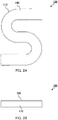
- FIG. 2A is a plan view of illumination apparatus 100
- FIG. 2B is a front view of illumination apparatus 100
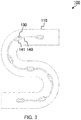
- FIG. 3 is a plan view of illumination apparatus 100 according to the present embodiment from which light diffusion plate 150 is removed.
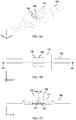
- FIGS. 4A to 4C illustrate a configuration of a region around light-emitting device 130 illustrated in FIG. 3 .
- FIG. 4A is a perspective view of a region around light-emitting device 130 illustrated in FIG. 3
- FIG. 4B is a plan view of FIG. 4A
- FIG. 4C is a sectional view taken along line 4C-4C of FIG. 4B .
- Illumination apparatus 100 illustrated in the drawings are used as a channel letter signboard, for example.
- illumination apparatus 100 includes housing 110, a plurality of substrates 120 (not illustrated in the drawing), a plurality of light-emitting devices 130, cable 140 and light diffusion plate 150.
- Housing 110 is a box-shaped member whose one surface is at least partially open and configured to house therein the plurality of substrates 120 and the plurality of light-emitting devices 130.
- housing 110 is composed of a bottom plate, a top plate opposite the bottom plate, and four side plates configured to connect the bottom plate and the top plate.
- an opening serving as a light emission region is formed in the top plate. This opening is closed with light diffusion plate 150.
- the bottom plate and the top plate are parallel to each other.
- the height (space thickness) from the surface of the bottom plate to light diffusion plate 150 is, but not limited to, approximately 20 to 100 mm.
- housing 110 is composed of a resin such as polymethylmethacrylate (PMMA) and polycarbonate (PC), a metal such as stainless steel and aluminum or the like.
- Housing 110 may have any shape in plan view.
- housing 110 has an S-shape in plan view because it is used for a channel letter signboard and the like.
- the plurality of substrates 120 are flat plates for disposing the plurality of light-emitting devices 130 on the bottom plate of housing 110 at a predetermined interval (see FIG. 4C ).
- substrate 120 is disposed on the bottom plate of housing 110 with caulking material 141 described later therebetween (see FIG. 4C ).
- the wiring line of substrate 120 is electrically connected by cable 140.
- the plurality of light-emitting devices 130 are disposed on the bottom plate of housing 110 with respective substrates 120 therebetween.
- the number of light-emitting devices 130 disposed on the bottom plate of housing 110 is not limited.
- the number of light-emitting devices 130 disposed on the bottom plate of housing 110 is appropriately set based on the size of the light emission region (light-emitting surface) defined by the opening of housing 110.
- Each light-emitting device 130 includes light-emitting element 131 and light flux controlling member 132. Each light-emitting device 130 is disposed such that the light axis of light emitted from light-emitting element 131 (light axis LA of light-emitting element 131 described later) is along the normal to the surface of substrate 120.
- Light-emitting element 131 is a light source of illumination apparatus 100 (and light-emitting device 130). Light-emitting element 131 is disposed on substrate 120 (see FIG. 4C ), and is electrically connected to a wiring line formed on or in substrate 120.
- Light-emitting element 131 is a light-emitting diode (LED), for example.
- the emission light color of light-emitting element 131 included in light-emitting device 130 is not limited. In the present embodiment, for example, it is possible to use a light-emitting element of an SMD-type including a light emission part that emits blue light, and a phosphor that covers the periphery of the light emission part and converts blue light emitted from the light emission part into white light.
- Light flux controlling member 132 controls the distribution of light emitted from light-emitting element 131, and changes the travelling direction of the light to the plane direction substrate 120, or more specifically, to two opposite directions approximately perpendicular to light axis LA of light-emitting element 131.
- Light flux controlling member 132 is disposed over light-emitting element 131 such that its central axis CA is aligned with light axis LA oflight-emitting element 131 (see FIG. 4C ).
- the "light axis LA of light-emitting element 131" means a central light beam of a stereoscopic light flux emitted from light-emitting element 131.
- the "central axis CA of light flux controlling member 132" is a 2-fold rotationally symmetric axis, for example.
- a Z-axis direction the direction that passes through the light emission center of light-emitting element 131 and is parallel to light axis LA of light-emitting element 131
- X-axis direction and a Y-axis direction two directions orthogonal to each other in a plane perpendicular to the Z-axis direction.
- the direction in which two emission surfaces 135 described later are opposite to each other is the Y-axis direction
- the direction orthogonal to the Y-axis direction in a plane perpendicular to the Z-axis direction is the X-axis direction.
- the material of light flux controlling member 132 is not limited as long as light of a desired wavelength can pass therethrough.
- Examples of the material of light flux controlling member 132 include optically transparent resins such as polymethylmethacrylate (PMMA), polycarbonate (PC), and epoxy resin (EP), and glass.
- a main feature of illumination apparatus 100 according to the present embodiment is the configuration of light flux controlling member 132. Therefore, light flux controlling member 132 is elaborated later.
- Cable 140 electrically connects adjacent substrates 120.
- the connecting portion between substrate 120 and cable 140 is reinforced with caulking material 141 (see FIG. 4C ).
- caulking material 141 examples include urethane resin, silicone resin, and epoxy resin.
- the plurality of light-emitting devices 130 can be freely disposed in accordance with the shape of housing 110.
- Light diffusion plate 150 is disposed to close the opening of housing 110 (see FIGS. 2A and 2B ).
- Light diffusion plate 150 is an optically transparent and optically diffusive plate-shaped member, and allows light emitted from emission surface 135 (see FIG. 5 ) of light flux controlling member 132 to pass therethrough while diffusing the light.
- Light diffusion plate 150 can serve as a light-emitting surface of illumination apparatus 100, for example.
- the material of light diffusion plate 150 is not limited as long as light emitted from emission surface 135 of light flux controlling member 132 can pass therethrough while being diffused, and examples of such a material include optically transparent resins such as polymethylmethacrylate (PMMA), polycarbonate (PC), polystyrene (PS), and styrene methyl methacrylate copolymerization resin (MS).
- PMMA polymethylmethacrylate
- PC polycarbonate
- PS polystyrene
- MS styrene methyl methacrylate copolymerization resin
- minute irregularity is formed in the surface of light diffusion plate 150, or light diffusion members such as beads are dispersed inside light diffusion plate 150.
- illumination apparatus 100 In illumination apparatus 100 according to the present embodiment, light emitted from each light-emitting element 131 is emitted by light flux controlling member 132 while the direction is changed to two opposite directions approximately perpendicular to light axis LA of light-emitting element 131 so as to illuminate a wide range of light diffusion plate 150 (the Y-axis direction in FIGS. 4A to 4C ). Light emitted from each light flux controlling member 132 is further diffused by light diffusion plate 150, and emitted to the outside. Thus, color unevenness and illuminance unevenness of illumination apparatus 100 can be suppressed.
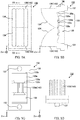
- FIGS. 5A to 5D illustrate a configuration of light flux controlling member 132.
- FIG. 5A is a plan view of light flux controlling member 132
- FIG. 5B is a sectional view taken along line 5B-5B of FIG. 5A
- FIG. 5C is a bottom view
- FIG. 5D is a side view.
- Light flux controlling member 132 controls the distribution of light emitted from light-emitting element 131. As illustrated in FIGS. 5A to 5D , light flux controlling member 132 includes incidence surface 133, two reflecting surfaces 134, two emission surfaces 135, flange part 136 and two leg parts 137. In the following description, in light flux controlling member 132, the side on which incidence surface is formed (light-emitting element 131 side) is the rear side, and the side on which reflecting surface 134 is formed is the front side.
- Incidence surface 133 allows incidence of part of light emitted from light-emitting element 131.
- Incidence surface 133 is an inner surface of recess 139 formed at a center portion of the rear side, i.e., bottom surface 138, of light flux controlling member 132.
- the inner surface shape of recess 139 is not limited, and may be an edged surface, or an edgeless curved surface of a shape such as a hemispherical shape and a semi-ellipsoid shape. In the present embodiment, the inner surface shape of recess 139 is an edged surface.
- the inner surface (incidence surface 133) of recess 139 includes at least first incidence surface 133a (top surface) and two second incidence surfaces 133b (side surface), and further includes two third incidence surfaces 133c, two fourth incidence surfaces 133d, and two fifth incidence surfaces 133e between first incidence surface 133a and two second incidence surfaces 133b (see FIGS. 5B and 5C ).
- Two second incidence surfaces 133b, two third incidence surfaces 133c, two fourth incidence surfaces 133d and two fifth incidence surfaces 133e are disposed to sandwich first incidence surface 133a in a direction parallel to the direction (Y-axis direction) in which two emission surfaces 135 are opposite to each other.
- First incidence surface 133a is a surface disposed at a center portion of recess 139 in such a manner as to intersect light axis LA of light-emitting element 131.
- first incidence surface 133a is formed such that light emitted from the light emission center of light-emitting element 131 at an angle of at least 0° to 10° with respect to light axis LA of light-emitting element 131 impinges on first incidence surface 133a.
- first incidence surface 133a is preferably formed such that the height from the light-emitting surface of light-emitting element 131 increases in the direction toward light axis LA of light-emitting element 131.
- a plurality of first ridges 142 are disposed in first incidence surface 133a for the purpose of suppressing color unevenness due to light-emitting element 131 (see FIG. 5C ).
- first ridge 142 in a cross-section perpendicular to the ridgeline of first ridge 142 is not limited, and may be a wavy shape, a triangular shape, or a rectangular shape (including a trapezoidal shape).
- the cross-sectional shape of first ridge 142 in a cross-section perpendicular to the ridgeline of first ridge 142 is a triangular shape (see FIG. 5C ).
- the plurality of first ridges 142 are disposed such that as viewed along light axis LA of the light-emitting element (as viewed along the Z-axis direction), the ridgelines of the plurality of first ridges 142 are approximately parallel to the direction (Y-axis direction) in which two emission surfaces 135 are opposite to each other. It should be noted that, the extending direction of first ridge 142 may not be aligned with the Y-axis direction.
- the plurality of first ridges are formed to extend, without intersecting each other, toward two emission surfaces 135 from a virtual plane, which includes light axis LA (an XZ plane including the X axis and the Z axis) between two reflecting surfaces 134.
- a virtual plane which includes light axis LA (an XZ plane including the X axis and the Z axis) between two reflecting surfaces 134.
- first ridge 142 means a continuous line of the topmost portion of the ridge (apex), and is a line obtained by connecting the vertex of first ridge 142 in a cross-section that includes light axis LA of light-emitting element 131 and is parallel to the X-axis direction.
- Each first ridge 142 may include one "ridgeline", or two or more "ridgelines”.
- the ridgeline is one line connecting the vertex of a wave.
- first ridge 142 is a trapezoidal shape
- the ridgeline is two lines, namely, a line connecting the points of one of two vertexes (intersections of the upper bottom and the legs) of a trapezoid, and a line connecting the points of the other of the two vertexes.
- center-to-center distances a (the distances in the X-axis direction) of the plurality of first ridges 142 may be or may not be equal to each other. From the viewpoint of suppressing color unevenness while achieving a desired light distribution, center-to-center distances a of the plurality of first ridges 142 are preferably equal to each other.
- the "center-to-center distance a of the plurality of first ridges 142" is a distance between center lines of the first ridges 142 (see FIG. 6 ).
- heights b (lengths in the Z axis) of the plurality of first ridges 142 may be or may not be equal to each other. From the viewpoint of suppressing color unevenness while achieving a desired light distribution, heights b of the plurality of first ridges 142 are preferably equal to each other.
- the "height b of first ridge 142" means a length corresponding to half of the distance between a straight line connecting the vertexes of two adjacent first ridges 142 and a straight line connecting valley bottoms of a recess formed between the two first ridges 142 and two recesses formed on both sides of thereof in a cross-section perpendicular to the ridgeline of first ridge 142 (see FIG. 6 ).
- Heights b of the plurality of first ridges 142 may be or may not be equal to each other in the extending direction of the ridgeline of first ridge 142 (Y-axis direction). In the present embodiment, heights b of the plurality of first ridges 142 are equal to each other in the extending direction of the ridgeline (Y-axis direction).
- the travelling direction of light entered from first incidence surface 133a can be slightly changed without largely affecting the illuminance distribution on light diffusion plate 150, and therefore color unevenness can be easily suppressed while achieving a desired light distribution.
- center-to-center distance a of the plurality of first ridges 142 is preferably 0.1 mm to 1 mm.
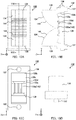
- FIG. 6 is a graph illustrating an exemplary cross-sectional shape of first incidence surface 133a in a cross-section perpendicular to the ridgeline of first ridge 142.
- the abscissa indicates distance d1 from the center of first incidence surface 133a (the distance in the X-axis direction; mm), and the ordinate indicates height h1 of first incidence surface 133a from a reference plane (the height in the Z-axis direction; mm).
- the reference plane is a line connecting each middle point between the vertex of first ridge 142 and the next valley bottom in a cross-section perpendicular to the ridgeline of first ridge 142.
- Two reflecting surfaces 134 are disposed on the front side of light flux controlling member 132, i.e., on the side opposite to light-emitting element 131 (light diffusion plate 150 side) with incidence surface 133 therebetween.
- two reflecting surfaces 134 reflect a part of light entered from incidence surface 133 in two opposite directions (the direction in which two emission surfaces 135 are opposite to each other, i.e., the Y-axis direction) substantially perpendicular to light axis LA of light-emitting element 131.
- each of two reflecting surfaces 134 is disposed such that, with respect to light axis LA of light-emitting element 131, the height from bottom surface 138 (substrate 120) increases in the direction toward the end portion (emission surface 135) from light axis LA of light-emitting element 131. More specifically, in the cross-section, each of two reflecting surfaces 134 is formed such that the inclination of the tangent gradually decreases in the direction toward the end portion (emission surface 135) from light axis LA of light-emitting element 131.
- Two emission surfaces 135 are disposed opposite to each other with two reflecting surfaces 134 therebetween. Two emission surfaces 135 emit, to the outside, light having entered from incidence surface 133 and having directly reached emission surface 135, and light reflected by two reflecting surfaces 134. For the purpose of suppressing color unevenness due to light-emitting element 131, a plurality of second ridges 143 are disposed in two emission surfaces 135 (see FIGS. 5A and 5D ).
- the cross-sectional shape of second ridge 143 in a cross-section perpendicular to the ridgeline of second ridge 143 is not limited, and may be a wavy shape, a triangular shape, or a rectangular shape (including a trapezoidal shape).
- the cross-sectional shape of second ridge 143 is a wavy shape in a cross-section perpendicular to the ridgeline of second ridge 143.
- the ridgeline of second ridge 143 is approximately parallel to light axis LA of light-emitting element 131.
- the "approximately parallel” means that the angle between light axis LA of light-emitting element 131 and the ridgeline of second ridge 143 as viewed along the Y-axis direction is 15° or smaller, preferably 0°.
- the reason for setting the angle between light axis LA and the ridgeline of second ridge 143 as small as possible is to easily remove the molded article from the metal mold without complicating the structure of the metal mold for light flux controlling member 132.
- the limitation on the inclination angle with respect to light axis LA can be eliminated.
- the angle between light axis LA and the ridgeline of second ridge 143 can be large.
- the "ridgeline" of second ridge 143 means a continuous line of the topmost portion of the ridge, and is a line connecting vertex of second ridge 143 in a cross-section perpendicular to light axis LA of light-emitting element 131.
- center-to-center distance a (the distance in the X-axis direction) of the plurality of second ridges 143 may be or may not be equal to each other. From the viewpoint of suppressing color unevenness while achieving a desired light distribution, center-to-center distance a of the plurality of second ridges 143 are preferably equal to each other. As described above, the "center-to-center distance a of the plurality of second ridges 143" is the distance between each center line of second ridges 143 in a cross-section perpendicular to the ridgeline of second ridge 143 (see FIG. 7 ).
- heights b of the plurality of second ridges 143 may be or may not be equal to each other. From a view point of the ease of processing of the metal mold, heights b of the plurality of second ridges 143 are preferably equal to each other.
- height b of second ridge 143 means the length corresponding to half of the distance between a straight line connecting the vertexes of adjacent two second ridges 143, and a straight line connecting the valley bottoms of a recess formed between two second ridges 143 and two recesses formed on both sides of thereof in a cross-section perpendicular to the ridgeline of second ridge 143 (see FIG. 7 ).
- heights b of the plurality of second ridges 143 may be or may not be equal to each other.
- the ratio a:b falls within the above-mentioned range, the travelling direction of the light emitted from two emission surfaces 135 can be slightly changed without scattering the light, and therefore color unevenness can be easily suppressed while achieving a desired light distribution.
- center-to-center distance a of the plurality of second ridges 143 is set such that the ratio of center-to-center distance a and height b of the plurality of second ridges 143 falls within the above-described range, and is preferably 0.125 mm to 4.000 mm.
- center-to-center distance a of the plurality of second ridges 143 falls within the above-mentioned range, the effect of suppressing the color unevenness can be easily achieved.
- center-to-center distance a of the plurality of second ridges 143 is preferably not smaller than 0.125 mm and equal to or smaller than 2.000 mm.
- FIG. 7 is a graph illustrating an exemplary cross-sectional shape of emission surface 135 in a cross-section perpendicular to the ridgeline of second ridge 143.
- the abscissa indicates distance d1 (the distance in the X-axis direction; mm) from a center of emission surface 135 of light flux controlling member 132
- the ordinate indicates height h2 (the height in the Y-axis direction; mm) from a reference plane of emission surface 135.
- the reference plane is a line connecting each middle point between the vertex of second ridge 143 and the next valley bottom in a cross-section perpendicular to the ridgeline of second ridge 143.
- the cross-sectional shape of emission surface 135 of light flux controlling member 132 is set to satisfy Expression (1).
- hy b ⁇ cos 2 ⁇ dx / a (where a: the center-to-center distance of the plurality of second ridges 143 (mm), b: the height of second ridge 143 (mm), d1: the distance from the center in emission surface 135 (the distance in the X-axis direction; mm), and h2: the height of emission surface 135 from the reference plane (the height in the Y-axis direction; mm))
- Flange part 136 is located between each of two emission surfaces 135 and the outer periphery part of bottom surface 138 of light flux controlling member 132, and protrudes to the outside with respect to central axis CA.
- Flange part 136 has a substantially rectangular shape.
- Flange part 136 is not an essential component, but light flux controlling member 132 can be easily handled and positioned by means of flange part 136.
- the thickness of flange part 136 is not limited, and may be determined in consideration of the required planar dimensions of two emission surfaces 135 and the workability of flange part 136.
- Two leg parts 137 are members having a substantially columnar shape protruding from bottom surface 138 and the bottom of flange part 136 toward light-emitting element 131 side at the outer periphery part of bottom surface 138 (rear surface) of light flux controlling member 132.
- Two leg parts 137 support light flux controlling member 132 at an appropriate position with respect to light-emitting element 131 (see FIG. 5C ).
- Leg part 137 may be fitted to a hole formed in substrate 120 so as to position in the direction parallel to the XY plane. Note that the number of leg parts 137 is not limited.
- light flux controlling member 132 The operation of light flux controlling member 132 according to the present embodiment is described by comparison with a comparative light flux controlling member.
- the comparative light flux controlling member is identical to the light flux controlling member according to the present embodiment except that the plurality of first ridges 142 are not provided in first incidence surface 133a, and that the plurality of second ridges 143 are not provided in two emission surfaces 135.
- the comparative light flux controlling member (not illustrated in the drawing) and light flux controlling member 132 of the present embodiment
- light emitted from light-emitting element 131 is entered from incidence surface 133. Apart of the light is reflected by two reflecting surfaces 134 so as to advance in two opposite directions perpendicular to light axis LA of light-emitting element 131, and then the light is emitted to the outside from two emission surfaces 135.
- the light emitted from emission surface 135 is controlled to reach a position remote from light-emitting device 130 in light diffusion plate 150 (see FIGS. 4C and 5B ).
- first incidence surface 133a and two emission surfaces 135 are smooth surfaces. Accordingly, light emitted at a small angle with respect to light axis LA of light-emitting element 131 (e.g., at least at an angle of 0° to 10° with respect to light axis LA oflight-emitting element 131 from the light emission center of light-emitting element 131) is entered from the smooth surface, and as such the travelling direction of the light is not disturbed, and the light tends to reach a specific region of light diffusion plate 150 in a concentrate manner. As a result, the blue in the specific region of light-emitting element 131 is stronger than in other regions, and consequently color unevenness is easily caused.
- the plurality of first ridges 142 are disposed in first incidence surface 133a (see FIG. 5C ), and the plurality of second ridges 143 are disposed in two emission surfaces 135 (see FIG. 5A ).
- the travelling direction of the light emitted at a small angle with respect to light axis LA of light-emitting element 131 is moderately changed by the plurality of first ridges 142 of first incidence surface 133a, and then the travelling direction of the light is further changed by the plurality of second ridges 143 of emission surface 135.
- the light emitted at a small angle with respect to light axis LA of light-emitting element 131 is moderately scattered in the Z-axis direction without concentrating at a specific region of light diffusion plate 150.
- color unevenness can be sufficiently suppressed without impairing the distribution characteristics of the light emitted from light-emitting element 131.
- the chromaticity Y value and the illuminance distribution on the light diffusion plate were analyzed also in illumination apparatuses using light flux controlling member R1 (comparison 1) that is identical to light flux controlling member A except that neither first incidence surface 133a nor two emission surfaces 135 have a ridge, and light flux controlling member R2 (comparison 2) that is identical to light flux controlling member A except that no ridge is provided in two emission surfaces 135.
- the ratio of center-to-center distance a and height b and center-to-center distance a were set as follows for the plurality of first ridges 142 of first incidence surface 133a and the plurality of second ridges 143 of two emission surfaces 135.
- the shape of emission surface 135 including the plurality of second ridges 143 in a cross-section perpendicular to the ridgeline of second ridge 143 was set to satisfy Expression (1).
- Outer diameter of light flux controlling member 132 11.1 mm in length in the Y axis direction, and 9.2 mm in length in the X axis direction Height of light-emitting element 131: 0.75 mm Size of light-emitting element 131: ⁇ 2.8 mm Distance between substrate 120 and light diffusion plate 150: 50 mm
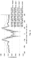
- FIG. 8 is a graph illustrating an analysis result of the chromaticity Y value on the light diffusion plate of the illumination apparatus according to the present embodiment, and an analysis result of the chromaticity Y value on the light diffusion plate of the comparative illumination apparatus.
- the abscissa indicates distance d2 (the distance in the Y-axis direction; mm) from light axis LA of light-emitting element 131 in light diffusion plate 150, and the ordinate indicates the chromaticity Y value in light diffusion plate 150.
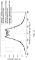
- FIG. 9 is a graph illustrating an analysis result of the illuminance distribution on the light diffusion plate of the illumination apparatus according to the present embodiment, and an analysis result the illuminance distribution on the light diffusion plate of the comparative illumination apparatus.
- the abscissa indicates distance d2 (the distance in the Y-axis direction; mm) from light axis LA of light-emitting element 131 in light diffusion plate 150, and the ordinate indicates a relative illuminance with respect to a maximum illuminance set as 1 at each distance in light diffusion plate 150.
- the chromaticity Y value is excessively low when distance d2 from light axis LA of light-emitting element 131 is approximately 40 mm (specific region), and bluish color unevenness is caused.
- the chromaticity Y value is not excessively low when distance d2 from light axis LA of light-emitting element 131 is approximately 40 mm, and the color unevenness is reduced.
- the illuminance distribution of the illumination apparatus using light flux controlling member A according to the present embodiment is comparable to the illuminance distribution of the illumination apparatus using the comparative light flux controlling member in terms of light expansion in the Y-axis direction, and favorable light distribution characteristics are maintained.
- the illumination apparatus using the light flux controlling member according to the present embodiment can prevent the chromaticity Y value from becoming excessively low when distance d2 from light axis LA of light-emitting element 131 is approximately 40 mm and can sufficiently suppress the color unevenness while favorably maintaining the light distribution characteristics.
- the plurality of first ridges 142 and the plurality of second ridges 143 are provided in first incidence surface 133a and two emission surfaces 135, respectively.
- FIGS. 10A to 10D illustrate a configuration of the light flux controlling member according to Embodiment 2.
- FIG. 10A is a plan view of light flux controlling member 132
- FIG. 10B is a sectional view of taken along line 10B-10B of FIG. 10A
- FIG. 10C is a bottom view
- FIG. 10D is a side view.
- Light flux controlling member 132 according to the present embodiment differs from light flux controlling member 132 according to Embodiment 1 in that two reflecting surfaces 134 include a plurality of third ridges 144 instead of the plurality of second ridges 143 in two emission surfaces 135.
- the same components as those of light flux controlling member 132 according to Embodiment 1 are denoted with the same reference signs, and the description thereof will be omitted.
- the plurality of third ridges 144 are additionally disposed in at least a part of two reflecting surfaces 134, preferably in a region where light entered from first incidence surface 133a reaches (see FIGS. 10A and 10B ).
- the region where light entered from first incidence surface 133a reaches in two reflecting surfaces 134 is, for example, a region around light axis LA of light-emitting element 131 in two reflecting surfaces 134 (see FIG. 10B ).
- third ridge 144 is formed such that the ridgeline thereof is substantially orthogonal to the ridgeline of first ridge 142.
- substantially orthogonal means that the angle between the ridgeline of first ridge 142 and the ridgeline of third ridge 144 is 90 ⁇ 5° or smaller, preferably 90°.
- the "ridgeline" of third ridge 144 means a continuous line connecting the topmost portion of the ridge, and is a line obtained by connecting the vertex of third ridge 144 in a cross-section that includes light axis LA of light-emitting element 131 and is parallel to the Y-axis direction.
- the plurality of third ridges 144 may be disposed such that the ridgeline is approximately parallel to X-axis direction (see FIG. 10A ), or may be disposed as a part of a circle surrounding light axis LA (not illustrated in the drawing).
- third ridge 144 in a cross-section perpendicular to the ridgeline of third ridge 144 is not limited, and may be a wavy shape, a triangular shape, or a rectangular shape (including a trapezoidal shape).
- Center-to-center distance a of the plurality of third ridges 144 (the distance in the Y-axis direction) in a cross-section perpendicular to the ridgeline of third ridge 144 may be or may not be equal to each other.
- center-to-center distance a of the plurality of third ridges 144 may be gradually reduced in the direction away from light axis LA of light-emitting element 131 in the Y-axis direction.
- center-to-center distance a of the plurality of third ridges 144 means the distance between the center lines of third ridges 144 adjacent to each other in a cross-section that includes light axis LA of light-emitting element 131 and is parallel to the Y-axis direction.
- Heights b of the plurality of third ridges 144 (the length in the Z axis direction) in a cross-section perpendicular to the ridgeline of third ridge 144 may be or may not be equal to each other.
- height b of third ridge 144 may be gradually reduced in the direction away from light axis LA oflight-emitting element 131 in the Y-axis direction.
- the "height b of third ridge 144" means the length corresponding to half of the distance between a straight line connecting the vertexes of two third ridges 144 adjacent to each other, and a straight line connecting the valley bottoms of a recess formed between two third ridges 144 and two recesses formed on both sides thereof in a cross-section perpendicular to the ridgeline of third ridge 143.
- the plurality of first ridges 142 are disposed in first incidence surface 133a, and further, the plurality of third ridges 144 are additionally disposed in two reflecting surfaces 134.
- the travelling direction of the light whose travelling direction is changed by first ridge 142 can be further changed by third ridge 144, and thus color unevenness can be more significantly suppressed.
- the chromaticity Y value and the illuminance distribution on the light diffusion plate were analyzed also in illumination apparatuses using light flux controlling member R1 (comparison 1) that is identical to light flux controlling member B except that neither first incidence surface 133a nor two reflecting surfaces 134 have a ridge, and light flux controlling member R3 (comparison 3) that is identical to light flux controlling member B except that no ridge is provided in two reflecting surfaces 134.
- the ratio of center-to-center distance a and height b and center-to-center distance a were set as follows for the plurality of first ridges 142 of first incidence surface 133a and the plurality of third ridges 144 of two reflecting surfaces 134.
- Other common parameters were set as in Simulation 1.
- the cross-sectional shape of two reflecting surfaces 134 of light flux controlling member B in a cross-section perpendicular to the ridgeline of third ridge 144 (a cross-section that includes light axis LA of light-emitting element 131 and is parallel to the Y-axis direction) was set.
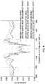
- FIG. 11A is a graph illustrating a part of a cross-sectional shape of reflecting surface 134 of light flux controlling member B in a cross-section perpendicular to the ridgeline of third ridge 144.
- FIG. 11B is a graph illustrating a result ( ⁇ h1; mm) obtained by subtracting an analysis result of the cross-sectional shape of reflecting surface 134 of a light flux controlling member that is identical to light flux controlling member B except that no third ridge 144 is provided, from an analysis result of the cross-sectional shape of reflecting surface 134 of light flux controlling member B of FIGS. 10A to 10D including third ridge 144 in a cross-section perpendicular to the ridgeline of third ridge 144.
- the abscissa indicates distance d2 from light axis LA of light-emitting element 131 (the distance in the Y-axis direction; mm).
- the ordinate indicates height h1 of reflecting surface 134 from bottom surface 138 (the height in the Z-axis direction; mm) with respect to intersection of light axis LA of light-emitting element 131.
- FIG. 11A the abscissa indicates distance d2 from light axis LA of light-emitting element 131 (the distance in the Y-axis direction; mm).
- the ordinate indicates height h1 of reflecting surface 134 from bottom surface 138 (the height in the Z-axis direction; mm) with respect to intersection of light axis LA of light-emitting element 131.
- the ordinate indicates value ⁇ h1 (the height in the Z-axis direction; mm) obtained by subtracting the cross-sectional shape of reflecting surface 134 of a light flux controlling member including no third ridge 144 from the cross-sectional shape of reflecting surface 134 of light flux controlling member B including third ridge 144.
- FIG. 12 is a graph illustrating an analysis result of the chromaticity Y value on the light diffusion plate of the illumination apparatus according to the present embodiment, and an analysis result of the chromaticity Y value on the light diffusion plate of the comparative illumination apparatus.
- the abscissa indicates distance d2 (the distance in the Y-axis direction; mm) from light axis LA of light-emitting element 131 in light diffusion plate 150, and the ordinate indicates the chromaticity Y value in light diffusion plate 150.
- FIG. 13 is a graph illustrating an analysis result of the illuminance distribution on the light diffusion plate of the illumination apparatus according to the present embodiment, and an analysis result the illuminance distribution on the light diffusion plate of the comparative illumination apparatus.
- the abscissa indicates distance d2 (the distance in the Y-axis direction; mm) from light axis LA of light-emitting element 131 in light diffusion plate 150, and the ordinate indicates a relative illuminance with respect to a maximum illuminance set as 1 at each distance in light diffusion plate 150.
- the chromaticity Y value is excessively low when distance d2 from light axis LA of light-emitting element 131 is approximately 40 mm, and bluish color unevenness is caused.
- the chromaticity Y value is not excessively low when distance d2 from light axis LA of light-emitting element 131 is approximately 40 mm, and the color unevenness is reduced.
- the illuminance distribution of the illumination apparatus using light flux controlling member B according to the present embodiment is comparable to the illuminance distribution of the illumination apparatus using the comparative light flux controlling member in terms of light expansion of the Y-axis direction, and favorable light distribution characteristics are maintained.
- the illumination apparatus using the light flux controlling member according to the present embodiment can prevent the chromaticity Y value from becoming locally excessively lowered when distance d2 from light axis LA of light-emitting element 131 is approximately 40 mm, and can sufficiently suppress the color unevenness while favorably maintaining the light distribution characteristics.
- the plurality of first ridges 142 are disposed in first incidence surface 133a, and further, the plurality of third ridges 144 are additionally disposed in two reflecting surfaces 134.
- FIGS. 14A to 14D illustrate a configuration of the light flux controlling member according to Embodiment 3.
- FIG. 14A is a plan view of light flux controlling member 132
- FIG. 14B is a sectional view taken along line 14B-14B of FIG. 14A
- FIG. 14C is a bottom view
- FIG. 14D is a side view.
- Light flux controlling member 132 according to the present embodiment differs from light flux controlling member 132 according to Embodiment 1 in that two reflecting surfaces 134 further include the plurality of third ridges 144. In view of this, the same components as those of light flux controlling member 132 according to Embodiment 1 are denoted with the same reference signs, and the description thereof will be omitted.
- the plurality of third ridges 144 are additionally disposed in at least a part of two reflecting surfaces 134, preferably in a region where light entered from first incidence surface 133a reaches (see FIGS. 14A and 14B ).
- the plurality of third ridges 144 are identical to those of Embodiment 2. That is, as viewed along light axis LA of light-emitting element 131 (as viewed along the Z-axis direction), third ridge 144 is formed such that the ridgeline thereof is substantially orthogonal to the ridgeline of first ridge 142.
- the chromaticity Y value and the illuminance distribution on the light diffusion plate were analyzed also in an illumination apparatus using light flux controlling member R1 (comparison 1) that is identical to light flux controlling member C except that neither first incidence surface 133a, two reflecting surfaces 134 nor two emission surfaces 135 have a ridge, and light flux controlling member A (Embodiment 1) that is identical to light flux controlling member C except that only two reflecting surfaces 134 are not provided with a ridge, and an illumination apparatus using light flux controlling member B (Embodiment 2) that is identical to light flux controlling member C except that only two emission surfaces 135 are not provided with a ridge.
- the ratio of center-to-center distance a and height b and center-to-center distance a were set for the plurality of first ridges 142 of first incidence surface 133a and the plurality of second ridges 143 of two emission surfaces 135 as in Simulation 1.
- the ratio of center-to-center distance a and height b and center-to-center distance of the plurality of third ridges 144 of two reflecting surfaces 134 were set as in Simulation 2.
- Other common parameters were set as in Simulation 1.
- FIG. 15 is a graph illustrating an analysis result of the chromaticity Y value on the light diffusion plate of the illumination apparatus according to the present embodiment, and an analysis result of the chromaticity Y value on the light diffusion plate of the comparative illumination apparatus.
- the abscissa indicates distance d2 (the distance in the Y-axis direction; mm) from light axis LA of light-emitting element 131 in light diffusion plate 150, and the ordinate indicates the chromaticity Y value in light diffusion plate 150.
- FIG. 16 is a graph illustrating an analysis result of the illuminance distribution on the light diffusion plate of the illumination apparatus according to the present embodiment, and an analysis result the illuminance distribution on the light diffusion plate of the comparative illumination apparatus.
- the abscissa indicates distance d2 (the distance in the Y-axis direction; mm) from light axis LA of light-emitting element 131 in light diffusion plate 150, and the ordinate indicates a relative illuminance with respect to a maximum illuminance set as 1 at each distance in light diffusion plate 150.
- the chromaticity Y value is excessively low when distance d2 from light axis LA of light-emitting element 131 is approximately 40 mm, and bluish color unevenness is caused.
- the chromaticity Y value is not excessively low when distance d2 from light axis LA of light-emitting element 131 is approximately 40 mm, and the color unevenness is significantly reduced.
- the illuminance distribution of the illumination apparatus using light flux controlling member C according to the present embodiment is comparable to the illuminance distributions of the illumination apparatus using comparative light flux controlling member R1, and the illumination apparatuses using light flux controlling member A of Embodiment 1 and light flux controlling member B of Embodiment 2 in terms of light expansion in the Y-axis direction, and favorable light distribution characteristics are maintained.
- the illumination apparatus using the light flux controlling member according to the present embodiment can further prevent the chromaticity Y value from becoming excessively low when distance d2 from light axis LA of light-emitting element 131 is approximately 40 mm, and can further suppress the color unevenness while favorably maintaining the light distribution characteristics.
- the plurality of first ridges 142 are disposed in first incidence surface 133a, and the plurality of second ridges 143 are disposed in two emission surfaces 135, and further, the plurality of third ridges 144 are additionally disposed in two reflecting surfaces 134.
- first ridges 142 are provided only in a center portion of first incidence surface 133a in light flux controlling member 132 in Embodiments 1 to 3, the present invention is not limited to this, and the plurality of first ridges 142 may be provided in the entirety of first incidence surface 133a.
- the plurality of second ridges 143 are provided in the entire surface of emission surface 135 in Embodiments 1 and 3, the present invention is not limited to this, and the plurality of second ridges 143 may be provided only in a part of emission surface 135.
- first incidence surface 133a that is a flat surface in light flux controlling member 132 in Embodiments 1 to 3
- the present invention is not limited to this, and the plurality of first ridges 142 may be provided in first incidence surface 133a that is a curved surface (e.g., a recessed surface).
- first incidence surface 133a, third incidence surface 133c, fourth incidence surface 133d, fifth incidence surface 133e and second incidence surface 133b may be continuously (successively) formed.
- recess 139 further includes two third incidence surfaces 133c, two fourth incidence surfaces 133d, and two fifth incidence surfaces 133e in addition to first incidence surface 133a (top surface) and two second incidence surfaces 133b (side surface) in light flux controlling member 132 in Embodiments 1 to 3, the present invention is not limited to this, and at least one of two third incidence surfaces 133c, two fourth incidence surfaces 133d and two fifth incidence surfaces 133e may be omitted.
- two emission surfaces 135 are approximately parallel (not tilted) to light axis LA of light-emitting element 131 in a cross-section that includes light axis LA of light-emitting element 131 and is parallel to the Y-axis direction in light flux controlling member 132 in Embodiments 1 to 3, the present invention is not limited to this, and two emission surfaces 135 may be slightly tilted with respect to light axis LA of light-emitting element 131.
- emission surface 135 may be tilted toward light axis LA of light-emitting element 131 in the direction away from light-emitting element 131 along the Z axis in a cross-section that includes light axis LA of light-emitting element 131 and is parallel to the Y-axis direction.
- the inclination angle of emission surface 135 with respect to light axis LA of light-emitting element 131 in a cross-section that includes light axis LA of light-emitting element 131 and is parallel to the Y-axis direction may be 10° or smaller, for example.
- the present invention is not limited to this, and the plurality of light-emitting devices 130 may be disposed in two or more lines.
- the present invention is not limited to this, and the plurality of light-emitting devices 130 may be disposed on one substrate 120. In such a case, cable 140 and caulking material 141 are unnecessary.
- housing 100 is a box-shaped member including a bottom plate, a four side plates, and a top plate (provided with an opening in at least a part of the plate) in illumination apparatus 100 in Embodiments 1 to 3, the present invention is not limited to this, and the side plate and the top plate may be omitted as long as at least bottom plate is provided.
- FIG. 17 is a partially enlarged perspective view illustrating a configuration of an illumination apparatus according to a modification. As illustrated in FIG. 17 , the top plate and the side plate of housing 110 may be omitted such that the bottom plate of housing 110 is covered with only light diffusion plate 150.
- illumination apparatus 100 is a channel letter signboard in Embodiments 1 to 3, the present invention is not limited to this, and illumination apparatus 100 may be a line illumination.
- the illumination apparatus including the light flux controlling member according to the embodiment of the present invention is applicable to a signboard (in particular, a channel letter signboard), a line illumination, a generally-used illumination apparatus and the like, for example.
Landscapes
- Physics & Mathematics (AREA)
- Engineering & Computer Science (AREA)
- General Engineering & Computer Science (AREA)
- General Physics & Mathematics (AREA)
- Optics & Photonics (AREA)
- Planar Illumination Modules (AREA)
- Non-Portable Lighting Devices Or Systems Thereof (AREA)
- Optical Elements Other Than Lenses (AREA)
- Illuminated Signs And Luminous Advertising (AREA)
- Led Device Packages (AREA)
Abstract
Description
- The present invention relates to a light flux controlling member, a light-emitting device and an illumination apparatus.
- A light-emitting device including a light-emitting element such as an LED is used as a light source of an illumination apparatus and a sign board. Among them, as a light source of a channel letter sign board having a special shape, a light-emitting device is used in which light emitted from a light-emitting element is reflected in two opposite directions along the horizontal direction so as to have anisotropic light distribution characteristics (or have an elliptic light distribution).
- As a light-emitting device having an anisotropic light distribution characteristics,
PTL 1 discloses a light-emitting device including light-emittingelement 12, base (chip mounting lead) 14 havingreflection cup 14a configured to reflect light emitted from light-emittingelement 12 upward, and light flux controlling member 13 (inPTL 1, an optically transparent resin) configured to cover light-emittingelement 12 andreflection cup 14a as illustrated inFIG. 1 , for example. Lightflux controlling member 13 includes two reflectingsurfaces 17 configured to reflect light emitted from light-emittingelement 12 and light reflected byreflection cup 14a, and two emission surfaces 19 (inPTL 1, a side surface) configured to emit, to outside, light reflected by reflectingsurface 17. - In such a light-emitting device, light emitted from the top surface of light-emitting
element 12 directly reaches reflectingsurface 17 of lightflux controlling member 13, and light emitted from a side surface of light-emittingelement 12 is reflected byreflection cup 14a and thereafter reaches two reflectingsurfaces 17 of lightflux controlling member 13. Then, the light beams having reached two reflectingsurfaces 17 of lightflux controlling member 13 advance in opposite directions along the horizontal direction, and are emitted to outside from twoemission surfaces 19 of lightflux controlling member 13. - A light-emitting element such as an LED is used for a light-emitting element used for such a light-emitting device. Many inexpensive and mass-produced LEDs are light-emitting elements (SMD-type light-emitting elements) with a light-emitting part that emits blue light and a phosphor that covers its surrounding area and converts the blue light emitted from the light-emitting part into white light, for example.
-
PTL 1 Japanese Patent Application Laid-Open No.H9-18058 - In the SMD-type light-emitting element, blue light emitted at a large angle to the light axis of the light-emitting element is easily converted to white light because it is emitted by propagating a long light path within the phosphor layer. On the other hand, blue light emitted at a small angle to the light axis of the light-emitting element is difficult to be converted to white light because the light path within the phosphor layer is short, and thus tends to be emitted as blueish light. When a light-emitting element, which is not limited to the SMD-type light-emitting element, configured to emit light with different colors depending on the output direction is applied to a light-emitting device with anisotropic light distribution characteristics, as disclosed in
PTL 1, there is a problem of unevenness of color between the region where the light emitted at a small angle to the light axis of the light-emitting element reaches and the region where the light emitted at a large angle to the light axis reaches. Specifically, the light emitted at a small angle to the light axis of the light-emitting element tends to reach a specific area of the light diffusing plate in a concentrate manner, thus producing a strong blue color in that area. - In view of this, an object of the present invention is to provide a light flux controlling member that can suppress color unevenness due to a light-emitting element while maintaining desired light distribution characteristics. In addition, another object of the present invention is to provide a light-emitting device and an illumination apparatus including the light flux controlling member.
- A light flux controlling member according to the present invention is configured to control a distribution of light emitted from a light-emitting element, the light flux controlling member including: an incidence surface that is an inner surface of a recess disposed on a rear side, the incidence surface being configured to enter the light emitted from light-emitting element; two reflecting surfaces disposed on a front side, and configured to reflect a part of light entered from the incidence surface, in two opposite directions substantially perpendicular to a light axis of the light-emitting element; and two emission surfaces disposed opposite to each other with the two reflecting surfaces between the two emission surfaces, the two emission surfaces being configured to emit, to outside, light reflected by the two reflecting surfaces. The incidence surface includes a first incidence surface disposed to intersect the light axis of the light-emitting element, and two second incidence surfaces disposed to sandwich the first incidence surface between the two second incidence surfaces in a direction in which the two emission surfaces are opposite to each other, A plurality of first ridges are disposed in the first incidence surface, the plurality of first ridges having ridgelines that are approximately parallel to the direction in which the two emission surfaces are opposite to each other as viewed along the light axis of the light-emitting element. A plurality of second ridges having ridgelines that are approximately parallel to the light axis of the light-emitting element as viewed along the direction in which the two emission surfaces are opposite to each other are provided in each of the two emission surfaces, or a plurality of third ridges having ridgelines that are substantially orthogonal to the ridgelines of the plurality of first ridges as viewed along the light axis of the light-emitting element are disposed in at least a part of each of the two reflecting surfaces.
- Alight-emitting device according to the present invention includes a light-emitting element; and the light flux controlling member in which the first incidence surface is disposed to intersect the light axis of the light-emitting element.
- An illumination apparatus according to the present invention includes a plurality of the light-emitting devices; and a light diffusion plate configured to allow light emitted from the light-emitting device to pass through the light diffusion plate while diffusing the light.
- According to the present invention, it is possible to provide a light flux controlling member that can suppress color unevenness due to a light-emitting element while maintaining desired light distribution characteristics.
-
-
FIG. 1 illustrates a configuration of a conventional light-emitting device; -
FIGS. 2A and 2B illustrate a configuration of an illumination apparatus according toEmbodiment 1; -
FIG. 3 is a plan view of an illumination apparatus in the state where a light diffusion plate is removed; -
FIGS. 4A to 4C illustrate a configuration of a region around a light-emitting device illustrated inFIG. 3 ; -
FIGS. 5A to 5D illustrate a configuration of a light flux controlling member according toEmbodiment 1; -
FIG. 6 is a graph illustrating an exemplary cross-sectional shape of a first incidence surface; -
FIG. 7 is a graph illustrating an exemplary cross-sectional shape of an emission surface; -
FIG. 8 is a graph illustrating an analysis result of a chromaticity Y value on a light diffusion plate in an illumination apparatus using the light flux controlling member according toEmbodiment 1, and an analysis result of a chromaticity Y value on a light diffusion plate in an illumination apparatus using a comparative light flux controlling member; -
FIG. 9 is a graph illustrating an analysis result of an illuminance distribution on the light diffusion plate in the illumination apparatus using the light flux controlling member according toEmbodiment 1, and an analysis result of an illuminance distribution on the light diffusion plate in the illumination apparatus using the comparative light flux controlling member; -
FIGS. 10A to 10D illustrate a configuration of a light flux controlling member according toEmbodiment 2; -
FIG. 11A is a graph illustrating a cross-sectional shape of a reflecting surface of a light flux controlling member in a cross-section perpendicular to a ridgeline of a third ridge,FIG. 11B is a graph illustrating a result (Δh1) obtained by subtracting a set value of a cross-sectional shape of a reflecting surface of a light flux controlling member including no third ridge from a set value of a cross-sectional shape of a reflecting surface of a light flux controlling member including a third ridge in the cross-section perpendicular to the ridgeline of the third ridge; -
FIG. 12 is a graph illustrating an analysis result of a chromaticity Y value on the light diffusion plate in the illumination apparatus using the light flux controlling member according toEmbodiment 2, and an analysis result of a chromaticity Y value on the light diffusion plate in the illumination apparatus using the comparative light flux controlling member; -
FIG. 13 is a graph illustrating an analysis result of an illuminance distribution on the light diffusion plate in the illumination apparatus using the light flux controlling member according toEmbodiment 2, and an analysis result of an illuminance distribution on the light diffusion plate in the illumination apparatus using the comparative light flux controlling member; -
FIGS. 14A to 14D illustrate a configuration of a light flux controlling member according toEmbodiment 3; -
FIG. 15 is a graph illustrating an analysis result of a chromaticity Y value on the light diffusion plate in an illumination apparatus using the light flux controlling member according toEmbodiment 3, and an analysis result of a chromaticity Y value on the light diffusion plate in the illumination apparatus using the comparative light flux controlling member; -
FIG. 16 is a graph illustrating an analysis result of an illuminance distribution on the light diffusion plate in the illumination apparatus using the light flux controlling member according toEmbodiment 3, and an analysis result of an illuminance distribution on the light diffusion plate in the illumination apparatus using the comparative light flux controlling member; and -
FIG. 17 is a partially enlarged perspective view illustrating a configuration of an illumination apparatus according to a modification. - An embodiment of the present invention is elaborated below with reference to the accompanying drawings.
-
FIGS. 2A, 2B , andFIG. 3 illustrate a configuration ofillumination apparatus 100 according toEmbodiment 1.FIG. 2A is a plan view ofillumination apparatus 100, andFIG. 2B is a front view ofillumination apparatus 100.FIG. 3 is a plan view ofillumination apparatus 100 according to the present embodiment from whichlight diffusion plate 150 is removed.FIGS. 4A to 4C illustrate a configuration of a region around light-emitting device 130 illustrated inFIG. 3 .FIG. 4A is a perspective view of a region around light-emittingdevice 130 illustrated inFIG. 3 ,FIG. 4B is a plan view ofFIG. 4A, and FIG. 4C is a sectional view taken alongline 4C-4C ofFIG. 4B .Illumination apparatus 100 illustrated in the drawings are used as a channel letter signboard, for example. - As illustrated in
FIGS. 2A, 2B and3 ,illumination apparatus 100 includeshousing 110, a plurality of substrates 120 (not illustrated in the drawing), a plurality of light-emittingdevices 130,cable 140 andlight diffusion plate 150. -
Housing 110 is a box-shaped member whose one surface is at least partially open and configured to house therein the plurality ofsubstrates 120 and the plurality of light-emittingdevices 130. In the present embodiment,housing 110 is composed of a bottom plate, a top plate opposite the bottom plate, and four side plates configured to connect the bottom plate and the top plate. In the top plate, an opening serving as a light emission region is formed. This opening is closed withlight diffusion plate 150. The bottom plate and the top plate are parallel to each other. The height (space thickness) from the surface of the bottom plate tolight diffusion plate 150 is, but not limited to, approximately 20 to 100 mm. For example,housing 110 is composed of a resin such as polymethylmethacrylate (PMMA) and polycarbonate (PC), a metal such as stainless steel and aluminum or the like. -
Housing 110 may have any shape in plan view. In the present embodiment,housing 110 has an S-shape in plan view because it is used for a channel letter signboard and the like. - The plurality of
substrates 120 are flat plates for disposing the plurality of light-emittingdevices 130 on the bottom plate ofhousing 110 at a predetermined interval (seeFIG. 4C ). In the present embodiment,substrate 120 is disposed on the bottom plate ofhousing 110 withcaulking material 141 described later therebetween (seeFIG. 4C ). The wiring line ofsubstrate 120 is electrically connected bycable 140. - The plurality of light-emitting
devices 130 are disposed on the bottom plate ofhousing 110 withrespective substrates 120 therebetween. The number of light-emittingdevices 130 disposed on the bottom plate ofhousing 110 is not limited. The number of light-emittingdevices 130 disposed on the bottom plate ofhousing 110 is appropriately set based on the size of the light emission region (light-emitting surface) defined by the opening ofhousing 110. - Each light-emitting
device 130 includes light-emittingelement 131 and lightflux controlling member 132. Each light-emittingdevice 130 is disposed such that the light axis of light emitted from light-emitting element 131 (light axis LA of light-emittingelement 131 described later) is along the normal to the surface ofsubstrate 120. - Light-emitting
element 131 is a light source of illumination apparatus 100 (and light-emitting device 130). Light-emittingelement 131 is disposed on substrate 120 (seeFIG. 4C ), and is electrically connected to a wiring line formed on or insubstrate 120. - Light-emitting
element 131 is a light-emitting diode (LED), for example. The emission light color of light-emittingelement 131 included in light-emittingdevice 130 is not limited. In the present embodiment, for example, it is possible to use a light-emitting element of an SMD-type including a light emission part that emits blue light, and a phosphor that covers the periphery of the light emission part and converts blue light emitted from the light emission part into white light. - Light
flux controlling member 132 controls the distribution of light emitted from light-emittingelement 131, and changes the travelling direction of the light to theplane direction substrate 120, or more specifically, to two opposite directions approximately perpendicular to light axis LA of light-emittingelement 131. Lightflux controlling member 132 is disposed over light-emittingelement 131 such that its central axis CA is aligned with light axis LA oflight-emitting element 131 (seeFIG. 4C ). The "light axis LA of light-emittingelement 131" means a central light beam of a stereoscopic light flux emitted from light-emittingelement 131. The "central axis CA of lightflux controlling member 132" is a 2-fold rotationally symmetric axis, for example. In the following description, in each light-emittingdevice 130, the direction that passes through the light emission center of light-emittingelement 131 and is parallel to light axis LA of light-emittingelement 131 is referred to as a Z-axis direction, and two directions orthogonal to each other in a plane perpendicular to the Z-axis direction are referred to as an X-axis direction and a Y-axis direction. More specifically, in lightflux controlling member 132 described later, the direction in which twoemission surfaces 135 described later are opposite to each other is the Y-axis direction, and the direction orthogonal to the Y-axis direction in a plane perpendicular to the Z-axis direction is the X-axis direction. - The material of light
flux controlling member 132 is not limited as long as light of a desired wavelength can pass therethrough. Examples of the material of lightflux controlling member 132 include optically transparent resins such as polymethylmethacrylate (PMMA), polycarbonate (PC), and epoxy resin (EP), and glass. - A main feature of
illumination apparatus 100 according to the present embodiment is the configuration of lightflux controlling member 132. Therefore, lightflux controlling member 132 is elaborated later. -
Cable 140 electrically connectsadjacent substrates 120. The connecting portion betweensubstrate 120 andcable 140 is reinforced with caulking material 141 (seeFIG. 4C ). Examples of the material ofcaulking material 141 include urethane resin, silicone resin, and epoxy resin. - As described above, by electrically connecting the plurality of light-emitting
devices 130 throughcable 140 to form a module, the plurality of light-emittingdevices 130 can be freely disposed in accordance with the shape ofhousing 110. -
Light diffusion plate 150 is disposed to close the opening of housing 110 (seeFIGS. 2A and 2B ).Light diffusion plate 150 is an optically transparent and optically diffusive plate-shaped member, and allows light emitted from emission surface 135 (seeFIG. 5 ) of lightflux controlling member 132 to pass therethrough while diffusing the light.Light diffusion plate 150 can serve as a light-emitting surface ofillumination apparatus 100, for example. - The material of
light diffusion plate 150 is not limited as long as light emitted fromemission surface 135 of lightflux controlling member 132 can pass therethrough while being diffused, and examples of such a material include optically transparent resins such as polymethylmethacrylate (PMMA), polycarbonate (PC), polystyrene (PS), and styrene methyl methacrylate copolymerization resin (MS). To provide the light diffusing property, minute irregularity is formed in the surface oflight diffusion plate 150, or light diffusion members such as beads are dispersed insidelight diffusion plate 150. - In
illumination apparatus 100 according to the present embodiment, light emitted from each light-emittingelement 131 is emitted by lightflux controlling member 132 while the direction is changed to two opposite directions approximately perpendicular to light axis LA of light-emittingelement 131 so as to illuminate a wide range of light diffusion plate 150 (the Y-axis direction inFIGS. 4A to 4C ). Light emitted from each lightflux controlling member 132 is further diffused bylight diffusion plate 150, and emitted to the outside. Thus, color unevenness and illuminance unevenness ofillumination apparatus 100 can be suppressed. -
FIGS. 5A to 5D illustrate a configuration of lightflux controlling member 132.FIG. 5A is a plan view of lightflux controlling member 132,FIG. 5B is a sectional view taken alongline 5B-5B ofFIG. 5A, FIG. 5C is a bottom view, andFIG. 5D is a side view. - Light
flux controlling member 132 controls the distribution of light emitted from light-emittingelement 131. As illustrated inFIGS. 5A to 5D , lightflux controlling member 132 includesincidence surface 133, two reflectingsurfaces 134, twoemission surfaces 135,flange part 136 and twoleg parts 137. In the following description, in lightflux controlling member 132, the side on which incidence surface is formed (light-emittingelement 131 side) is the rear side, and the side on which reflectingsurface 134 is formed is the front side. -
Incidence surface 133 allows incidence of part of light emitted from light-emittingelement 131.Incidence surface 133 is an inner surface ofrecess 139 formed at a center portion of the rear side, i.e.,bottom surface 138, of lightflux controlling member 132. The inner surface shape ofrecess 139 is not limited, and may be an edged surface, or an edgeless curved surface of a shape such as a hemispherical shape and a semi-ellipsoid shape. In the present embodiment, the inner surface shape ofrecess 139 is an edged surface. More specifically, the inner surface (incidence surface 133) ofrecess 139 includes at leastfirst incidence surface 133a (top surface) and two second incidence surfaces 133b (side surface), and further includes two third incidence surfaces 133c, two fourth incidence surfaces 133d, and twofifth incidence surfaces 133e betweenfirst incidence surface 133a and two second incidence surfaces 133b (seeFIGS. 5B and 5C ). Two second incidence surfaces 133b, two third incidence surfaces 133c, two fourth incidence surfaces 133d and twofifth incidence surfaces 133e are disposed to sandwichfirst incidence surface 133a in a direction parallel to the direction (Y-axis direction) in which twoemission surfaces 135 are opposite to each other. -
First incidence surface 133a is a surface disposed at a center portion ofrecess 139 in such a manner as to intersect light axis LA of light-emittingelement 131. Preferably,first incidence surface 133a is formed such that light emitted from the light emission center of light-emittingelement 131 at an angle of at least 0° to 10° with respect to light axis LA of light-emittingelement 131 impinges onfirst incidence surface 133a. In addition, from the viewpoint of preventing light emitted at a small angle with respect to light axis LA of light-emittingelement 131 from advancing to the boundary between two reflectingsurfaces 134,first incidence surface 133a is preferably formed such that the height from the light-emitting surface of light-emittingelement 131 increases in the direction toward light axis LA of light-emittingelement 131. A plurality offirst ridges 142 are disposed infirst incidence surface 133a for the purpose of suppressing color unevenness due to light-emitting element 131 (seeFIG. 5C ). - The cross-sectional shape of
first ridge 142 in a cross-section perpendicular to the ridgeline offirst ridge 142 is not limited, and may be a wavy shape, a triangular shape, or a rectangular shape (including a trapezoidal shape). In the present embodiment, the cross-sectional shape offirst ridge 142 in a cross-section perpendicular to the ridgeline offirst ridge 142 is a triangular shape (seeFIG. 5C ). - In the present embodiment, the plurality of
first ridges 142 are disposed such that as viewed along light axis LA of the light-emitting element (as viewed along the Z-axis direction), the ridgelines of the plurality offirst ridges 142 are approximately parallel to the direction (Y-axis direction) in which twoemission surfaces 135 are opposite to each other. It should be noted that, the extending direction offirst ridge 142 may not be aligned with the Y-axis direction. Specifically, it suffices that the plurality of first ridges are formed to extend, without intersecting each other, toward twoemission surfaces 135 from a virtual plane, which includes light axis LA (an XZ plane including the X axis and the Z axis) between two reflectingsurfaces 134. - The "ridgeline" of
first ridge 142 means a continuous line of the topmost portion of the ridge (apex), and is a line obtained by connecting the vertex offirst ridge 142 in a cross-section that includes light axis LA of light-emittingelement 131 and is parallel to the X-axis direction. Eachfirst ridge 142 may include one "ridgeline", or two or more "ridgelines". For example, in the case where the cross-sectional shape offirst ridge 142 is a wavy shape, the ridgeline is one line connecting the vertex of a wave. In the case where the cross-sectional shape offirst ridge 142 is a trapezoidal shape, the ridgeline is two lines, namely, a line connecting the points of one of two vertexes (intersections of the upper bottom and the legs) of a trapezoid, and a line connecting the points of the other of the two vertexes. - In a cross-section perpendicular to the ridgeline of
first ridge 142, center-to-center distances a (the distances in the X-axis direction) of the plurality offirst ridges 142 may be or may not be equal to each other. From the viewpoint of suppressing color unevenness while achieving a desired light distribution, center-to-center distances a of the plurality offirst ridges 142 are preferably equal to each other. The "center-to-center distance a of the plurality offirst ridges 142" is a distance between center lines of the first ridges 142 (seeFIG. 6 ). - In a cross-section perpendicular to the ridgeline of
first ridge 142, heights b (lengths in the Z axis) of the plurality offirst ridges 142 may be or may not be equal to each other. From the viewpoint of suppressing color unevenness while achieving a desired light distribution, heights b of the plurality offirst ridges 142 are preferably equal to each other. The "height b offirst ridge 142" means a length corresponding to half of the distance between a straight line connecting the vertexes of two adjacentfirst ridges 142 and a straight line connecting valley bottoms of a recess formed between the twofirst ridges 142 and two recesses formed on both sides of thereof in a cross-section perpendicular to the ridgeline of first ridge 142 (seeFIG. 6 ). - Heights b of the plurality of
first ridges 142 may be or may not be equal to each other in the extending direction of the ridgeline of first ridge 142 (Y-axis direction). In the present embodiment, heights b of the plurality offirst ridges 142 are equal to each other in the extending direction of the ridgeline (Y-axis direction). - In a cross-section perpendicular to the ridgeline of
first ridge 142, the ratio of center-to-center distance a and height b of the plurality offirst ridges 142 is preferably a:b=1:0.05 to 1:0.5. When the ratio a:b falls within the above-mentioned range, the travelling direction of light entered fromfirst incidence surface 133a can be slightly changed without largely affecting the illuminance distribution onlight diffusion plate 150, and therefore color unevenness can be easily suppressed while achieving a desired light distribution. - In consideration of improvement of the color unevenness, the processing accuracy of the metal mold, and the transferability in molding of the light flux controlling member, center-to-center distance a of the plurality of
first ridges 142 is preferably 0.1 mm to 1 mm. -
FIG. 6 is a graph illustrating an exemplary cross-sectional shape offirst incidence surface 133a in a cross-section perpendicular to the ridgeline offirst ridge 142. InFIG. 6 , the abscissa indicates distance d1 from the center offirst incidence surface 133a (the distance in the X-axis direction; mm), and the ordinate indicates height h1 offirst incidence surface 133a from a reference plane (the height in the Z-axis direction; mm). The reference plane is a line connecting each middle point between the vertex offirst ridge 142 and the next valley bottom in a cross-section perpendicular to the ridgeline offirst ridge 142. - Two reflecting
surfaces 134 are disposed on the front side of lightflux controlling member 132, i.e., on the side opposite to light-emitting element 131 (light diffusion plate 150 side) withincidence surface 133 therebetween. In addition, two reflectingsurfaces 134 reflect a part of light entered fromincidence surface 133 in two opposite directions (the direction in which twoemission surfaces 135 are opposite to each other, i.e., the Y-axis direction) substantially perpendicular to light axis LA of light-emittingelement 131. In a cross-section that includes light axis LA of light-emittingelement 131 and is parallel to the Y-axis direction, each of two reflectingsurfaces 134 is disposed such that, with respect to light axis LA of light-emittingelement 131, the height from bottom surface 138 (substrate 120) increases in the direction toward the end portion (emission surface 135) from light axis LA of light-emittingelement 131. More specifically, in the cross-section, each of two reflectingsurfaces 134 is formed such that the inclination of the tangent gradually decreases in the direction toward the end portion (emission surface 135) from light axis LA of light-emittingelement 131. - Two
emission surfaces 135 are disposed opposite to each other with two reflectingsurfaces 134 therebetween. Twoemission surfaces 135 emit, to the outside, light having entered fromincidence surface 133 and having directly reachedemission surface 135, and light reflected by two reflectingsurfaces 134. For the purpose of suppressing color unevenness due to light-emittingelement 131, a plurality ofsecond ridges 143 are disposed in two emission surfaces 135 (seeFIGS. 5A and 5D ). - The cross-sectional shape of
second ridge 143 in a cross-section perpendicular to the ridgeline ofsecond ridge 143 is not limited, and may be a wavy shape, a triangular shape, or a rectangular shape (including a trapezoidal shape). In the present embodiment, the cross-sectional shape ofsecond ridge 143 is a wavy shape in a cross-section perpendicular to the ridgeline ofsecond ridge 143. - As viewed in the direction (Y-axis direction) in which two
emission surfaces 135 are opposite to each other, the ridgeline ofsecond ridge 143 is approximately parallel to light axis LA of light-emittingelement 131. The "approximately parallel" means that the angle between light axis LA of light-emittingelement 131 and the ridgeline ofsecond ridge 143 as viewed along the Y-axis direction is 15° or smaller, preferably 0°. The reason for setting the angle between light axis LA and the ridgeline ofsecond ridge 143 as small as possible is to easily remove the molded article from the metal mold without complicating the structure of the metal mold for lightflux controlling member 132. In the case where a metal mold structure that slides in a direction intersecting the removal direction of the molded article can be employed, the limitation on the inclination angle with respect to light axis LA can be eliminated. In addition, when mounting lightflux controlling member 132 tosubstrate 120, the angle between light axis LA and the ridgeline ofsecond ridge 143 can be large. - As described above, the "ridgeline" of
second ridge 143 means a continuous line of the topmost portion of the ridge, and is a line connecting vertex ofsecond ridge 143 in a cross-section perpendicular to light axis LA of light-emittingelement 131. - In a cross-section perpendicular to the ridgeline of
second ridge 143, center-to-center distance a (the distance in the X-axis direction) of the plurality ofsecond ridges 143 may be or may not be equal to each other. From the viewpoint of suppressing color unevenness while achieving a desired light distribution, center-to-center distance a of the plurality ofsecond ridges 143 are preferably equal to each other. As described above, the "center-to-center distance a of the plurality ofsecond ridges 143" is the distance between each center line ofsecond ridges 143 in a cross-section perpendicular to the ridgeline of second ridge 143 (seeFIG. 7 ). - In a cross-section perpendicular to the ridgeline of
second ridge 143, heights b of the plurality of second ridges 143 (the length in the Y axis direction) may be or may not be equal to each other. From a view point of the ease of processing of the metal mold, heights b of the plurality ofsecond ridges 143 are preferably equal to each other. As described above, "height b ofsecond ridge 143" means the length corresponding to half of the distance between a straight line connecting the vertexes of adjacent twosecond ridges 143, and a straight line connecting the valley bottoms of a recess formed between twosecond ridges 143 and two recesses formed on both sides of thereof in a cross-section perpendicular to the ridgeline of second ridge 143 (seeFIG. 7 ). In the direction parallel to light axis LA of light-emitting element 131 (the Z-axis direction), heights b of the plurality ofsecond ridges 143 may be or may not be equal to each other. - In a cross-section perpendicular to the ridgeline of
second ridge 143, the ratio of center-to-center distance a and height b of the plurality ofsecond ridges 143 is preferably a:b=2:1 to 13:1. When the ratio a:b falls within the above-mentioned range, the travelling direction of the light emitted from twoemission surfaces 135 can be slightly changed without scattering the light, and therefore color unevenness can be easily suppressed while achieving a desired light distribution. Furthermore, to not only suppress the color unevenness but also to further improve the illuminance distribution, the ratio of center-to-center distance a and height b of the plurality ofsecond ridges 143 is more preferably a:b=5:1 to 11:1, still more preferably a:b=5:1 to 10:1. - It suffices that, in a cross-section perpendicular to the ridgeline of
second ridge 143, center-to-center distance a of the plurality ofsecond ridges 143 is set such that the ratio of center-to-center distance a and height b of the plurality ofsecond ridges 143 falls within the above-described range, and is preferably 0.125 mm to 4.000 mm. When center-to-center distance a of the plurality ofsecond ridges 143 falls within the above-mentioned range, the effect of suppressing the color unevenness can be easily achieved. Furthermore, in the case where the ratio of center-to-center distance a and height b of the plurality ofsecond ridges 143 is a:b=5:1 to 10:1, center-to-center distance a of the plurality ofsecond ridges 143 is preferably not smaller than 0.125 mm and equal to or smaller than 2.000 mm. -
FIG. 7 is a graph illustrating an exemplary cross-sectional shape ofemission surface 135 in a cross-section perpendicular to the ridgeline ofsecond ridge 143. InFIG. 7 , the abscissa indicates distance d1 (the distance in the X-axis direction; mm) from a center ofemission surface 135 of lightflux controlling member 132, and the ordinate indicates height h2 (the height in the Y-axis direction; mm) from a reference plane ofemission surface 135. The reference plane is a line connecting each middle point between the vertex ofsecond ridge 143 and the next valley bottom in a cross-section perpendicular to the ridgeline ofsecond ridge 143. - As illustrated in
FIG. 7 , in a cross-section perpendicular to the ridgeline ofsecond ridge 143, the cross-sectional shape ofemission surface 135 of lightflux controlling member 132 is set to satisfy Expression (1).
emission surface 135 from the reference plane (the height in the Y-axis direction; mm)) -
Flange part 136 is located between each of twoemission surfaces 135 and the outer periphery part ofbottom surface 138 of lightflux controlling member 132, and protrudes to the outside with respect to central axis CA.Flange part 136 has a substantially rectangular shape.Flange part 136 is not an essential component, but lightflux controlling member 132 can be easily handled and positioned by means offlange part 136. The thickness offlange part 136 is not limited, and may be determined in consideration of the required planar dimensions of twoemission surfaces 135 and the workability offlange part 136. - Two
leg parts 137 are members having a substantially columnar shape protruding frombottom surface 138 and the bottom offlange part 136 toward light-emittingelement 131 side at the outer periphery part of bottom surface 138 (rear surface) of lightflux controlling member 132. Twoleg parts 137 support lightflux controlling member 132 at an appropriate position with respect to light-emitting element 131 (seeFIG. 5C ).Leg part 137 may be fitted to a hole formed insubstrate 120 so as to position in the direction parallel to the XY plane. Note that the number ofleg parts 137 is not limited. - The operation of light
flux controlling member 132 according to the present embodiment is described by comparison with a comparative light flux controlling member. Note that the comparative light flux controlling member is identical to the light flux controlling member according to the present embodiment except that the plurality offirst ridges 142 are not provided infirst incidence surface 133a, and that the plurality ofsecond ridges 143 are not provided in two emission surfaces 135. - In the comparative light flux controlling member (not illustrated in the drawing) and light
flux controlling member 132 of the present embodiment, light emitted from light-emittingelement 131 is entered fromincidence surface 133. Apart of the light is reflected by two reflectingsurfaces 134 so as to advance in two opposite directions perpendicular to light axis LA of light-emittingelement 131, and then the light is emitted to the outside from two emission surfaces 135. The light emitted fromemission surface 135 is controlled to reach a position remote from light-emittingdevice 130 in light diffusion plate 150 (seeFIGS. 4C and5B ). - In the comparative light flux controlling member,
first incidence surface 133a and twoemission surfaces 135 are smooth surfaces. Accordingly, light emitted at a small angle with respect to light axis LA of light-emitting element 131 (e.g., at least at an angle of 0° to 10° with respect to light axis LA oflight-emittingelement 131 from the light emission center of light-emitting element 131) is entered from the smooth surface, and as such the travelling direction of the light is not disturbed, and the light tends to reach a specific region oflight diffusion plate 150 in a concentrate manner. As a result, the blue in the specific region of light-emittingelement 131 is stronger than in other regions, and consequently color unevenness is easily caused. - In contrast, in light
flux controlling member 132 of the present embodiment, the plurality offirst ridges 142 are disposed infirst incidence surface 133a (seeFIG. 5C ), and the plurality ofsecond ridges 143 are disposed in two emission surfaces 135 (seeFIG. 5A ). With this configuration, the travelling direction of the light emitted at a small angle with respect to light axis LA of light-emittingelement 131 is moderately changed by the plurality offirst ridges 142 offirst incidence surface 133a, and then the travelling direction of the light is further changed by the plurality ofsecond ridges 143 ofemission surface 135. As a result, the light emitted at a small angle with respect to light axis LA of light-emittingelement 131 is moderately scattered in the Z-axis direction without concentrating at a specific region oflight diffusion plate 150. As a result, color unevenness can be sufficiently suppressed without impairing the distribution characteristics of the light emitted from light-emittingelement 131. - In
Simulation 1, inillumination apparatus 100 using light flux controlling member A according to the present embodiment (lightflux controlling member 132 ofFIGS. 5A to 5D ), the chromaticity Y value and the illuminance distribution onlight diffusion plate 150 were analyzed. The chromaticity Y value and the illuminance distribution were analyzed inillumination apparatus 100 including only one light-emittingdevice 130. - In addition, for comparison, the chromaticity Y value and the illuminance distribution on the light diffusion plate were analyzed also in illumination apparatuses using light flux controlling member R1 (comparison 1) that is identical to light flux controlling member A except that neither
first incidence surface 133a nor twoemission surfaces 135 have a ridge, and light flux controlling member R2 (comparison 2) that is identical to light flux controlling member A except that no ridge is provided in two emission surfaces 135. - In light flux controlling member A (light
flux controlling member 132 ofFIGS. 5A to 5D ), the ratio of center-to-center distance a and height b and center-to-center distance a were set as follows for the plurality offirst ridges 142 offirst incidence surface 133a and the plurality ofsecond ridges 143 of two emission surfaces 135. - The cross-sectional shape of
first ridge 142 in a cross-section perpendicular to the ridgeline offirst ridge 142 was set to a triangular shape, and center-to-center distance a and height b of the plurality offirst ridges 142 were set as follows.
Center-to-center distance a:height b=1:0.14
Center-to-center distance a=500 µm, height b=72 µm - The shape of
emission surface 135 including the plurality ofsecond ridges 143 in a cross-section perpendicular to the ridgeline ofsecond ridge 143 was set to satisfy Expression (1). In addition, center-to-center distance a and height b of the plurality ofsecond ridges 143 in a cross-section perpendicular to the ridgeline ofsecond ridge 143 were set as follows.
Center-to-center distance a:height b=7.5:1
Center-to-center distance a=750 µm, height b=100 µm - Outer diameter of light flux controlling member 132: 11.1 mm in length in the Y axis direction, and 9.2 mm in length in the X axis direction
Height of light-emitting element 131: 0.75 mm
Size of light-emitting element 131: ϕ2.8 mm
Distance betweensubstrate 120 and light diffusion plate 150: 50 mm -
FIG. 8 is a graph illustrating an analysis result of the chromaticity Y value on the light diffusion plate of the illumination apparatus according to the present embodiment, and an analysis result of the chromaticity Y value on the light diffusion plate of the comparative illumination apparatus. InFIG. 8 , the abscissa indicates distance d2 (the distance in the Y-axis direction; mm) from light axis LA of light-emittingelement 131 inlight diffusion plate 150, and the ordinate indicates the chromaticity Y value inlight diffusion plate 150. -
FIG. 9 is a graph illustrating an analysis result of the illuminance distribution on the light diffusion plate of the illumination apparatus according to the present embodiment, and an analysis result the illuminance distribution on the light diffusion plate of the comparative illumination apparatus. InFIG. 9 , the abscissa indicates distance d2 (the distance in the Y-axis direction; mm) from light axis LA of light-emittingelement 131 inlight diffusion plate 150, and the ordinate indicates a relative illuminance with respect to a maximum illuminance set as 1 at each distance inlight diffusion plate 150. - As illustrated in
FIG. 8 , in the illumination apparatuses using comparative light flux controlling members R1 and R2, the chromaticity Y value is excessively low when distance d2 from light axis LA of light-emittingelement 131 is approximately 40 mm (specific region), and bluish color unevenness is caused. In contrast, inillumination apparatus 100 using light flux controlling member A according to the present embodiment, the chromaticity Y value is not excessively low when distance d2 from light axis LA of light-emittingelement 131 is approximately 40 mm, and the color unevenness is reduced. - In addition, as illustrated in
FIG. 9 , the illuminance distribution of the illumination apparatus using light flux controlling member A according to the present embodiment is comparable to the illuminance distribution of the illumination apparatus using the comparative light flux controlling member in terms of light expansion in the Y-axis direction, and favorable light distribution characteristics are maintained. - In view of the foregoing, the illumination apparatus using the light flux controlling member according to the present embodiment can prevent the chromaticity Y value from becoming excessively low when distance d2 from light axis LA of light-emitting
element 131 is approximately 40 mm and can sufficiently suppress the color unevenness while favorably maintaining the light distribution characteristics. - As described above, in light
flux controlling member 132 according to the present embodiment, the plurality offirst ridges 142 and the plurality ofsecond ridges 143 are provided infirst incidence surface 133a and twoemission surfaces 135, respectively. With this configuration, the emission direction of light emitted from light-emittingelement 131, especially light emitted at a small angle with respect to light axis LA of light-emittingelement 131 can be moderately changed and scattered without impairing the light distribution characteristics, and thus the color unevenness can be suppressed while maintaining desired light distribution characteristics. - Next, with reference to
FIG. 10 , lightflux controlling member 132 according toEmbodiment 2 is described.FIGS. 10A to 10D illustrate a configuration of the light flux controlling member according toEmbodiment 2.FIG. 10A is a plan view of lightflux controlling member 132,FIG. 10B is a sectional view of taken alongline 10B-10B ofFIG. 10A, FIG. 10C is a bottom view, andFIG. 10D is a side view. Lightflux controlling member 132 according to the present embodiment differs from lightflux controlling member 132 according toEmbodiment 1 in that two reflectingsurfaces 134 include a plurality ofthird ridges 144 instead of the plurality ofsecond ridges 143 in two emission surfaces 135. In view of this, the same components as those of lightflux controlling member 132 according toEmbodiment 1 are denoted with the same reference signs, and the description thereof will be omitted. - In light
flux controlling member 132 according to the present embodiment, the plurality ofthird ridges 144 are additionally disposed in at least a part of two reflectingsurfaces 134, preferably in a region where light entered fromfirst incidence surface 133a reaches (seeFIGS. 10A and 10B ). - The region where light entered from
first incidence surface 133a reaches in two reflectingsurfaces 134 is, for example, a region around light axis LA of light-emittingelement 131 in two reflecting surfaces 134 (seeFIG. 10B ). As viewed along light axis LA of light-emitting element 131 (as viewed along the Z-axis direction),third ridge 144 is formed such that the ridgeline thereof is substantially orthogonal to the ridgeline offirst ridge 142. Specifically, the "substantially orthogonal" means that the angle between the ridgeline offirst ridge 142 and the ridgeline ofthird ridge 144 is 90±5° or smaller, preferably 90°. - As described above, the "ridgeline" of
third ridge 144 means a continuous line connecting the topmost portion of the ridge, and is a line obtained by connecting the vertex ofthird ridge 144 in a cross-section that includes light axis LA of light-emittingelement 131 and is parallel to the Y-axis direction. As viewed along the Z-axis direction, the plurality ofthird ridges 144 may be disposed such that the ridgeline is approximately parallel to X-axis direction (seeFIG. 10A ), or may be disposed as a part of a circle surrounding light axis LA (not illustrated in the drawing). - The cross-sectional shape of
third ridge 144 in a cross-section perpendicular to the ridgeline of third ridge 144 (a cross-section that includes light axis LA of light-emittingelement 131 and is parallel to the Y-axis direction) is not limited, and may be a wavy shape, a triangular shape, or a rectangular shape (including a trapezoidal shape). - Center-to-center distance a of the plurality of third ridges 144 (the distance in the Y-axis direction) in a cross-section perpendicular to the ridgeline of
third ridge 144 may be or may not be equal to each other. For example, in a cross-section perpendicular to the ridgeline ofthird ridge 144, center-to-center distance a of the plurality ofthird ridges 144 may be gradually reduced in the direction away from light axis LA of light-emittingelement 131 in the Y-axis direction. As described above, center-to-center distance a of the plurality ofthird ridges 144 means the distance between the center lines ofthird ridges 144 adjacent to each other in a cross-section that includes light axis LA of light-emittingelement 131 and is parallel to the Y-axis direction. - Heights b of the plurality of third ridges 144 (the length in the Z axis direction) in a cross-section perpendicular to the ridgeline of
third ridge 144 may be or may not be equal to each other. For example, in a cross-section perpendicular to the ridgeline of third ridge 144 (a cross-section that includes light axis LA of light-emittingelement 131 and is parallel to the Y-axis direction), height b ofthird ridge 144 may be gradually reduced in the direction away from light axis LA oflight-emittingelement 131 in the Y-axis direction. The "height b ofthird ridge 144" means the length corresponding to half of the distance between a straight line connecting the vertexes of twothird ridges 144 adjacent to each other, and a straight line connecting the valley bottoms of a recess formed between twothird ridges 144 and two recesses formed on both sides thereof in a cross-section perpendicular to the ridgeline ofthird ridge 143. - As described above, in light
flux controlling member 132 according to the present embodiment, the plurality offirst ridges 142 are disposed infirst incidence surface 133a, and further, the plurality ofthird ridges 144 are additionally disposed in two reflectingsurfaces 134. With this configuration, the travelling direction of the light whose travelling direction is changed byfirst ridge 142 can be further changed bythird ridge 144, and thus color unevenness can be more significantly suppressed. - In
Simulation 2, inillumination apparatus 100 using light flux controlling member B according to the present embodiment (lightflux controlling member 132 ofFIGS. 10A to 10D ), the chromaticity Y value and the illuminance distribution onlight diffusion plate 150 were analyzed. The chromaticity Y value and the illuminance distribution were analyzed inillumination apparatus 100 including only one light-emittingdevice 130. - In addition, for comparison, the chromaticity Y value and the illuminance distribution on the light diffusion plate were analyzed also in illumination apparatuses using light flux controlling member R1 (comparison 1) that is identical to light flux controlling member B except that neither
first incidence surface 133a nor two reflectingsurfaces 134 have a ridge, and light flux controlling member R3 (comparison 3) that is identical to light flux controlling member B except that no ridge is provided in two reflectingsurfaces 134. - In light flux controlling member B (light
flux controlling member 132 ofFIGS. 10A to 10D ), the ratio of center-to-center distance a and height b and center-to-center distance a were set as follows for the plurality offirst ridges 142 offirst incidence surface 133a and the plurality ofthird ridges 144 of two reflectingsurfaces 134. Other common parameters were set as inSimulation 1. - In a cross-section perpendicular to the ridgeline of
first ridge 142, the cross-sectional shape offirst ridge 142 was set to a triangular shape, and center-to-center distance a and height b of the plurality offirst ridges 142 were set as follows.
Center-to-center distance a:height b=1:0.14
Center-to-center distance a=500 µm, height b=72 µm - First, the cross-sectional shape of two reflecting
surfaces 134 of light flux controlling member B in a cross-section perpendicular to the ridgeline of third ridge 144 (a cross-section that includes light axis LA of light-emittingelement 131 and is parallel to the Y-axis direction) was set. -
FIG. 11A is a graph illustrating a part of a cross-sectional shape of reflectingsurface 134 of light flux controlling member B in a cross-section perpendicular to the ridgeline ofthird ridge 144.FIG. 11B is a graph illustrating a result (Δh1; mm) obtained by subtracting an analysis result of the cross-sectional shape of reflectingsurface 134 of a light flux controlling member that is identical to light flux controlling member B except that nothird ridge 144 is provided, from an analysis result of the cross-sectional shape of reflectingsurface 134 of light flux controlling member B ofFIGS. 10A to 10D includingthird ridge 144 in a cross-section perpendicular to the ridgeline ofthird ridge 144. - In
FIGS. 11A and 11B , the abscissa indicates distance d2 from light axis LA of light-emitting element 131 (the distance in the Y-axis direction; mm). InFIG. 11A , the ordinate indicates height h1 of reflectingsurface 134 from bottom surface 138 (the height in the Z-axis direction; mm) with respect to intersection of light axis LA of light-emittingelement 131. InFIG. 11B , the ordinate indicates value Δh1 (the height in the Z-axis direction; mm) obtained by subtracting the cross-sectional shape of reflectingsurface 134 of a light flux controlling member including nothird ridge 144 from the cross-sectional shape of reflectingsurface 134 of light flux controlling member B includingthird ridge 144. - a: Center-to-center distance of third ridge 144 (mm)
- b: Height of third ridge 144 (the length in the Z axis direction; mm)
-
FIG. 12 is a graph illustrating an analysis result of the chromaticity Y value on the light diffusion plate of the illumination apparatus according to the present embodiment, and an analysis result of the chromaticity Y value on the light diffusion plate of the comparative illumination apparatus. InFIG. 12 , the abscissa indicates distance d2 (the distance in the Y-axis direction; mm) from light axis LA of light-emittingelement 131 inlight diffusion plate 150, and the ordinate indicates the chromaticity Y value inlight diffusion plate 150. -
FIG. 13 is a graph illustrating an analysis result of the illuminance distribution on the light diffusion plate of the illumination apparatus according to the present embodiment, and an analysis result the illuminance distribution on the light diffusion plate of the comparative illumination apparatus. InFIG. 13 , the abscissa indicates distance d2 (the distance in the Y-axis direction; mm) from light axis LA of light-emittingelement 131 inlight diffusion plate 150, and the ordinate indicates a relative illuminance with respect to a maximum illuminance set as 1 at each distance inlight diffusion plate 150. - As illustrated in
FIG. 12 , in illumination apparatuses using comparative light flux controlling members R1 and R3, the chromaticity Y value is excessively low when distance d2 from light axis LA of light-emittingelement 131 is approximately 40 mm, and bluish color unevenness is caused. In contrast, inillumination apparatus 100 using light flux controlling member B according to the present embodiment, the chromaticity Y value is not excessively low when distance d2 from light axis LA of light-emittingelement 131 is approximately 40 mm, and the color unevenness is reduced. - In addition, as illustrated in
FIG. 13 , the illuminance distribution of the illumination apparatus using light flux controlling member B according to the present embodiment is comparable to the illuminance distribution of the illumination apparatus using the comparative light flux controlling member in terms of light expansion of the Y-axis direction, and favorable light distribution characteristics are maintained. - In view of the foregoing, the illumination apparatus using the light flux controlling member according to the present embodiment can prevent the chromaticity Y value from becoming locally excessively lowered when distance d2 from light axis LA of light-emitting
element 131 is approximately 40 mm, and can sufficiently suppress the color unevenness while favorably maintaining the light distribution characteristics. - As described above, in light
flux controlling member 132 according to the present embodiment, the plurality offirst ridges 142 are disposed infirst incidence surface 133a, and further, the plurality ofthird ridges 144 are additionally disposed in two reflectingsurfaces 134. With this configuration, the emission direction of light emitted from light-emittingelement 131, especially light emitted at a small angle with respect to light axis LA of light-emittingelement 131 can be moderately changed and scattered without impairing the light distribution characteristics, and thus the color unevenness can be suppressed while maintaining desired light distribution characteristics. - Next, with reference to
FIG. 14 , lightflux controlling member 132 according toEmbodiment 3 is described.FIGS. 14A to 14D illustrate a configuration of the light flux controlling member according toEmbodiment 3.FIG. 14A is a plan view of lightflux controlling member 132,FIG. 14B is a sectional view taken alongline 14B-14B ofFIG. 14A, FIG. 14C is a bottom view, andFIG. 14D is a side view. Lightflux controlling member 132 according to the present embodiment differs from lightflux controlling member 132 according toEmbodiment 1 in that two reflectingsurfaces 134 further include the plurality ofthird ridges 144. In view of this, the same components as those of lightflux controlling member 132 according toEmbodiment 1 are denoted with the same reference signs, and the description thereof will be omitted. - In light
flux controlling member 132 according to the present embodiment, the plurality ofthird ridges 144 are additionally disposed in at least a part of two reflectingsurfaces 134, preferably in a region where light entered fromfirst incidence surface 133a reaches (seeFIGS. 14A and 14B ). The plurality ofthird ridges 144 are identical to those ofEmbodiment 2. That is, as viewed along light axis LA of light-emitting element 131 (as viewed along the Z-axis direction),third ridge 144 is formed such that the ridgeline thereof is substantially orthogonal to the ridgeline offirst ridge 142. - In
Simulation 3, inillumination apparatus 100 using light flux controlling member C according to the present embodiment (lightflux controlling member 132 ofFIGS. 14A to 14D ), the chromaticity Y value and the illuminance distribution onlight diffusion plate 150 were analyzed. The chromaticity Y value and the illuminance distribution were analyzed inillumination apparatus 100 including only one light-emittingdevice 130. - In addition, for comparison, the chromaticity Y value and the illuminance distribution on the light diffusion plate were analyzed also in an illumination apparatus using light flux controlling member R1 (comparison 1) that is identical to light flux controlling member C except that neither
first incidence surface 133a, two reflectingsurfaces 134 nor twoemission surfaces 135 have a ridge, and light flux controlling member A (Embodiment 1) that is identical to light flux controlling member C except that only two reflectingsurfaces 134 are not provided with a ridge, and an illumination apparatus using light flux controlling member B (Embodiment 2) that is identical to light flux controlling member C except that only twoemission surfaces 135 are not provided with a ridge. - In light flux controlling member C (light
flux controlling member 132 inFIGS. 14A to 14D ), the ratio of center-to-center distance a and height b and center-to-center distance a were set for the plurality offirst ridges 142 offirst incidence surface 133a and the plurality ofsecond ridges 143 of twoemission surfaces 135 as inSimulation 1. The ratio of center-to-center distance a and height b and center-to-center distance of the plurality ofthird ridges 144 of two reflectingsurfaces 134 were set as inSimulation 2. Other common parameters were set as inSimulation 1. -
FIG. 15 is a graph illustrating an analysis result of the chromaticity Y value on the light diffusion plate of the illumination apparatus according to the present embodiment, and an analysis result of the chromaticity Y value on the light diffusion plate of the comparative illumination apparatus. InFIG. 15 , the abscissa indicates distance d2 (the distance in the Y-axis direction; mm) from light axis LA of light-emittingelement 131 inlight diffusion plate 150, and the ordinate indicates the chromaticity Y value inlight diffusion plate 150. -
FIG. 16 is a graph illustrating an analysis result of the illuminance distribution on the light diffusion plate of the illumination apparatus according to the present embodiment, and an analysis result the illuminance distribution on the light diffusion plate of the comparative illumination apparatus. InFIG. 16 , the abscissa indicates distance d2 (the distance in the Y-axis direction; mm) from light axis LA of light-emittingelement 131 inlight diffusion plate 150, and the ordinate indicates a relative illuminance with respect to a maximum illuminance set as 1 at each distance inlight diffusion plate 150. - As illustrated in
FIG. 15 , in the illumination apparatus using comparative light flux controlling member R1, the chromaticity Y value is excessively low when distance d2 from light axis LA of light-emittingelement 131 is approximately 40 mm, and bluish color unevenness is caused. In contrast, inillumination apparatus 100 using light flux controlling members A to C, especially light flux controlling member C according to the present embodiment, the chromaticity Y value is not excessively low when distance d2 from light axis LA of light-emittingelement 131 is approximately 40 mm, and the color unevenness is significantly reduced. - In addition, as illustrated in
FIG. 16 , the illuminance distribution of the illumination apparatus using light flux controlling member C according to the present embodiment is comparable to the illuminance distributions of the illumination apparatus using comparative light flux controlling member R1, and the illumination apparatuses using light flux controlling member A ofEmbodiment 1 and light flux controlling member B ofEmbodiment 2 in terms of light expansion in the Y-axis direction, and favorable light distribution characteristics are maintained. - In view of the foregoing, the illumination apparatus using the light flux controlling member according to the present embodiment can further prevent the chromaticity Y value from becoming excessively low when distance d2 from light axis LA of light-emitting
element 131 is approximately 40 mm, and can further suppress the color unevenness while favorably maintaining the light distribution characteristics. - As described above, in light
flux controlling member 132 according to the present embodiment, the plurality offirst ridges 142 are disposed infirst incidence surface 133a, and the plurality ofsecond ridges 143 are disposed in twoemission surfaces 135, and further, the plurality ofthird ridges 144 are additionally disposed in two reflectingsurfaces 134. With this configuration, the emission direction of light emitted from light-emittingelement 131, especially light emitted at a small angle with respect to light axis LA of light-emittingelement 131 can be further changed and scattered without impairing the light distribution characteristics, and thus color unevenness can be further suppressed while maintaining desired light distribution characteristics. - While the plurality of
first ridges 142 are provided only in a center portion offirst incidence surface 133a in lightflux controlling member 132 inEmbodiments 1 to 3, the present invention is not limited to this, and the plurality offirst ridges 142 may be provided in the entirety offirst incidence surface 133a. Likewise, while the plurality ofsecond ridges 143 are provided in the entire surface ofemission surface 135 inEmbodiments second ridges 143 may be provided only in a part ofemission surface 135. - In addition, while the plurality of
first ridges 142 are provided infirst incidence surface 133a that is a flat surface in lightflux controlling member 132 inEmbodiments 1 to 3, the present invention is not limited to this, and the plurality offirst ridges 142 may be provided infirst incidence surface 133a that is a curved surface (e.g., a recessed surface). - In addition, while the inner surface shape of
recess 139 is an edged surface in lightflux controlling member 132 inEmbodiments 1 to 3, the present invention is not limited to this, and the inner surface shape ofrecess 139 may be an edgeless curved surface such as a hemispherical shape and a semi-ellipsoidal shape. In such a case,first incidence surface 133a,third incidence surface 133c,fourth incidence surface 133d,fifth incidence surface 133e andsecond incidence surface 133b may be continuously (successively) formed. - In addition, while the inner surface shape of
recess 139 further includes two third incidence surfaces 133c, two fourth incidence surfaces 133d, and twofifth incidence surfaces 133e in addition tofirst incidence surface 133a (top surface) and two second incidence surfaces 133b (side surface) in lightflux controlling member 132 inEmbodiments 1 to 3, the present invention is not limited to this, and at least one of two third incidence surfaces 133c, two fourth incidence surfaces 133d and twofifth incidence surfaces 133e may be omitted. - In addition, while two
emission surfaces 135 are approximately parallel (not tilted) to light axis LA of light-emittingelement 131 in a cross-section that includes light axis LA of light-emittingelement 131 and is parallel to the Y-axis direction in lightflux controlling member 132 inEmbodiments 1 to 3, the present invention is not limited to this, and twoemission surfaces 135 may be slightly tilted with respect to light axis LA of light-emittingelement 131. For example,emission surface 135 may be tilted toward light axis LA of light-emittingelement 131 in the direction away from light-emittingelement 131 along the Z axis in a cross-section that includes light axis LA of light-emittingelement 131 and is parallel to the Y-axis direction. The inclination angle ofemission surface 135 with respect to light axis LA of light-emittingelement 131 in a cross-section that includes light axis LA of light-emittingelement 131 and is parallel to the Y-axis direction may be 10° or smaller, for example. - In addition, while the plurality of light-emitting
devices 130 are disposed in a line inillumination apparatus 100 inEmbodiments 1 to 3, the present invention is not limited to this, and the plurality of light-emittingdevices 130 may be disposed in two or more lines. - In addition, while a plurality of
substrates 120 are disposed for respective light-emittingdevices 130 andsubstrates 120 are electrically connected throughcable 140 inillumination apparatus 100 inEmbodiments 1 to 3, the present invention is not limited to this, and the plurality of light-emittingdevices 130 may be disposed on onesubstrate 120. In such a case,cable 140 andcaulking material 141 are unnecessary. - In addition, while
housing 100 is a box-shaped member including a bottom plate, a four side plates, and a top plate (provided with an opening in at least a part of the plate) inillumination apparatus 100 inEmbodiments 1 to 3, the present invention is not limited to this, and the side plate and the top plate may be omitted as long as at least bottom plate is provided. -
FIG. 17 is a partially enlarged perspective view illustrating a configuration of an illumination apparatus according to a modification. As illustrated inFIG. 17 , the top plate and the side plate ofhousing 110 may be omitted such that the bottom plate ofhousing 110 is covered with onlylight diffusion plate 150. - In addition, while
illumination apparatus 100 is a channel letter signboard inEmbodiments 1 to 3, the present invention is not limited to this, andillumination apparatus 100 may be a line illumination. - This application is entitled to and claims the benefit of Japanese Patent Application No.
2018-027155 filed on February 19, 2018 - The illumination apparatus including the light flux controlling member according to the embodiment of the present invention is applicable to a signboard (in particular, a channel letter signboard), a line illumination, a generally-used illumination apparatus and the like, for example.
-
- 100
- Illumination apparatus
- 110
- Housing
- 120
- Substrate
- 130
- Light-emitting device
- 131
- Light-emitting element
- 132
- Light flux controlling member
- 133
- Incidence surface
- 133a
- First incidence surface
- 133b
- Second incidence surface
- 133c
- Third incidence surface
- 133d
- Fourth incidence surface
- 133e
- Fifth incidence surface
- 134
- Reflecting surface
- 135
- Emission surface
- 136
- Flange part
- 137
- Leg part
- 138
- Bottom surface
- 139
- Recess
- 140
- Cable
- 141
- Caulking material
- 142
- First ridge
- 143
- Second ridge
- 144
- Third ridge
- 150
- Light diffusion plate
- CA
- Central axis
- LA
- Light axis
Center-to-center distance a of
Claims (9)
- A light flux controlling member configured to control a distribution of light emitted from a light-emitting element, the light flux controlling member comprising:an incidence surface that is an inner surface of a recess disposed on a rear side, the incidence surface being configured to enter the light emitted from light-emitting element;two reflecting surfaces disposed on a front side, and configured to reflect a part of light entered from the incidence surface, in two opposite directions substantially perpendicular to a light axis of the light-emitting element; andtwo emission surfaces disposed opposite to each other with the two reflecting surfaces between the two emission surfaces, the two emission surfaces being configured to emit, to outside, light reflected by the two reflecting surfaces,wherein the incidence surface includes a first incidence surface disposed to intersect the light axis of the light-emitting element, and two second incidence surfaces disposed to sandwich the first incidence surface between the two second incidence surfaces in a direction in which the two emission surfaces are opposite to each other,wherein a plurality of first ridges are disposed in the first incidence surface, the plurality of first ridges having ridgelines that are approximately parallel to the direction in which the two emission surfaces are opposite to each other as viewed along the light axis of the light-emitting element, andwherein a plurality of second ridges having ridgelines that are approximately parallel to the light axis of the light-emitting element as viewed along the direction in which the two emission surfaces are opposite to each other are provided in each of the two emission surfaces, or a plurality of third ridges having ridgelines that are substantially orthogonal to the ridgelines of the plurality of first ridges as viewed along the light axis of the light-emitting element are disposed in at least a part of each of the two reflecting surfaces.
- The light flux controlling member according to claim 1, wherein the plurality of second ridges are disposed in each of the two emission surfaces.
- The light flux controlling member according to claim 2, wherein the plurality of third ridges are disposed in at least a part of each of the two reflecting surfaces.
- The light flux controlling member according to claim 1, wherein the plurality of third ridges are disposed in at least a part of each of the two reflecting surfaces.
- The light flux controlling member according to any one of claims 1 to 4, wherein in a cross-section perpendicular to the ridgelines of the plurality of first ridges, a ratio of a center-to-center distance a and a height b of the plurality of first ridges is a:b=1 :0.05 to 1:0.5.
- The light flux controlling member according to any one of claims 1 to 5, wherein in a cross section including the light axis of the light-emitting element, a height of the first incidence surface from a light-emitting surface of the light-emitting element increases in a direction toward the light axis of the light-emitting element.
- A light-emitting device comprising:a light-emitting element; andthe light flux controlling member according to any one of claims 1 to 6, wherein the first incidence surface is disposed to intersect the light axis of the light-emitting element.
- The light-emitting device according to claim 7, wherein light emitted from a light emission center of the light-emitting element at an angle of at least 0° to 10° with respect to the light axis of the light-emitting element impinges on the first incidence surface.
- An illumination apparatus comprising:a plurality of the light-emitting devices according to claim 7 or 8; anda light diffusion plate configured to allow light emitted from the light-emitting device to pass through the light diffusion plate while diffusing the light.
Applications Claiming Priority (2)
| Application Number | Priority Date | Filing Date | Title |
|---|---|---|---|
| JP2018027155A JP2019145278A (en) | 2018-02-19 | 2018-02-19 | Luminous flux control member, light emitting device, and illumination device |
| PCT/JP2019/005837 WO2019160137A1 (en) | 2018-02-19 | 2019-02-18 | Luminous flux control member, light emission device, and illumination device |
Publications (2)
| Publication Number | Publication Date |
|---|---|
| EP3757453A1 true EP3757453A1 (en) | 2020-12-30 |
| EP3757453A4 EP3757453A4 (en) | 2021-06-23 |
Family
ID=67621029
Family Applications (1)
| Application Number | Title | Priority Date | Filing Date |
|---|---|---|---|
| EP19753723.6A Withdrawn EP3757453A4 (en) | 2018-02-19 | 2019-02-18 | Luminous flux control member, light emission device, and illumination device |
Country Status (5)
| Country | Link |
|---|---|
| US (1) | US20210018162A1 (en) |
| EP (1) | EP3757453A4 (en) |
| JP (1) | JP2019145278A (en) |
| CN (1) | CN111742175A (en) |
| WO (1) | WO2019160137A1 (en) |
Families Citing this family (1)
| Publication number | Priority date | Publication date | Assignee | Title |
|---|---|---|---|---|
| JP7093712B2 (en) * | 2018-10-12 | 2022-06-30 | 株式会社エンプラス | Luminous flux control member, light emitting device and lighting device |
Family Cites Families (7)
| Publication number | Priority date | Publication date | Assignee | Title |
|---|---|---|---|---|
| JPH0918058A (en) | 1995-06-29 | 1997-01-17 | Sharp Corp | Light emitting semiconductor device |
| KR100644684B1 (en) * | 2005-02-26 | 2006-11-14 | 삼성전자주식회사 | Straight Side Light Emitter, Backlight System and Liquid Crystal Display Apparatus |
| JP6274974B2 (en) * | 2014-06-03 | 2018-02-07 | 株式会社エンプラス | Luminous flux control member, light emitting device, and illumination device |
| JP6437252B2 (en) * | 2014-09-11 | 2018-12-12 | 株式会社エンプラス | Luminous flux control member, light emitting device, and illumination device |
| JP2017092017A (en) * | 2015-11-09 | 2017-05-25 | 株式会社エンプラス | Luminous flux control member, light emitting device, surface light source device, and display device |
| JP2018027155A (en) | 2016-08-16 | 2018-02-22 | 安彦 杉本 | Stent |
| WO2018066418A1 (en) * | 2016-10-04 | 2018-04-12 | 株式会社エンプラス | Light bundle control member, light emitting device, and illuminating device |
-
2018
- 2018-02-19 JP JP2018027155A patent/JP2019145278A/en not_active Withdrawn
-
2019
- 2019-02-18 EP EP19753723.6A patent/EP3757453A4/en not_active Withdrawn
- 2019-02-18 WO PCT/JP2019/005837 patent/WO2019160137A1/en not_active Ceased
- 2019-02-18 US US16/970,741 patent/US20210018162A1/en not_active Abandoned
- 2019-02-18 CN CN201980014098.7A patent/CN111742175A/en not_active Withdrawn
Also Published As
| Publication number | Publication date |
|---|---|
| US20210018162A1 (en) | 2021-01-21 |
| CN111742175A (en) | 2020-10-02 |
| WO2019160137A1 (en) | 2019-08-22 |
| EP3757453A4 (en) | 2021-06-23 |
| JP2019145278A (en) | 2019-08-29 |
Similar Documents
| Publication | Publication Date | Title |
|---|---|---|
| JP4863357B2 (en) | Light emitting device, surface light source device, display device, and light flux controlling member | |
| EP2058679B1 (en) | Emission device, surface light source device and display | |
| EP1641052B1 (en) | Emission device, surface light source device, display and light flux control member | |
| US10520163B2 (en) | Light bundle control member, light emitting device, and illuminating device | |
| WO2018116816A1 (en) | Light guiding plate, surface light source device, display device, and electronic device | |
| US10393343B2 (en) | Light flux control member, light-emitting device, and area light source device | |
| US20150226907A1 (en) | Light guide module | |
| JP2015118906A (en) | Light guide plate and backlight unit | |
| US10302825B2 (en) | Reflective member and surface light source device having said reflective member | |
| EP3587911A1 (en) | Light-emitting device, planar light source device and display device | |
| US10794566B2 (en) | Light emitting device and surface light source device | |
| US10400988B2 (en) | Light emitting module and light emitting apparatus | |
| EP3588178A1 (en) | Planar lighting device | |
| US7517127B2 (en) | Light guide plate, including inclined surface, surface light source device and display using the same | |
| CN104698677A (en) | Optical element and light emitting device including the same | |
| US20210018162A1 (en) | Luminous flux control member, light emission device, and illumination device | |
| WO2018066418A1 (en) | Light bundle control member, light emitting device, and illuminating device | |
| US11099429B2 (en) | Surface light source device and display device | |
| US20210131641A1 (en) | Light flux control member, light-emitting device and surface light source device | |
| US20210072596A1 (en) | Light emitting device, surface light source device, and luminous flux control member | |
| US11243430B2 (en) | Light flux controlling member, light-emitting device, surface light source device and display device | |
| JP7093712B2 (en) | Luminous flux control member, light emitting device and lighting device | |
| US10802338B2 (en) | Light flux control member, light emitting device, and a surface light source device | |
| CN220041304U (en) | Light source module | |
| JP7197415B2 (en) | Luminous flux control member, light emitting device and lighting device |
Legal Events
| Date | Code | Title | Description |
|---|---|---|---|
| STAA | Information on the status of an ep patent application or granted ep patent |
Free format text: STATUS: THE INTERNATIONAL PUBLICATION HAS BEEN MADE |
|
| PUAI | Public reference made under article 153(3) epc to a published international application that has entered the european phase |
Free format text: ORIGINAL CODE: 0009012 |
|
| STAA | Information on the status of an ep patent application or granted ep patent |
Free format text: STATUS: REQUEST FOR EXAMINATION WAS MADE |
|
| 17P | Request for examination filed |
Effective date: 20200817 |
|
| AK | Designated contracting states |
Kind code of ref document: A1 Designated state(s): AL AT BE BG CH CY CZ DE DK EE ES FI FR GB GR HR HU IE IS IT LI LT LU LV MC MK MT NL NO PL PT RO RS SE SI SK SM TR |
|
| AX | Request for extension of the european patent |
Extension state: BA ME |
|
| DAV | Request for validation of the european patent (deleted) | ||
| DAX | Request for extension of the european patent (deleted) | ||
| A4 | Supplementary search report drawn up and despatched |
Effective date: 20210525 |
|
| RIC1 | Information provided on ipc code assigned before grant |
Ipc: F21V 5/08 20060101AFI20210518BHEP Ipc: F21V 7/00 20060101ALI20210518BHEP Ipc: G02B 19/00 20060101ALI20210518BHEP Ipc: H01L 33/58 20100101ALI20210518BHEP Ipc: F21V 5/00 20180101ALN20210518BHEP Ipc: F21S 4/10 20160101ALN20210518BHEP Ipc: F21Y 115/10 20160101ALN20210518BHEP |
|
| STAA | Information on the status of an ep patent application or granted ep patent |
Free format text: STATUS: THE APPLICATION IS DEEMED TO BE WITHDRAWN |
|
| 18D | Application deemed to be withdrawn |
Effective date: 20211222 |