EP3757420B1 - Kopplung - Google Patents
Kopplung Download PDFInfo
- Publication number
- EP3757420B1 EP3757420B1 EP19182297.2A EP19182297A EP3757420B1 EP 3757420 B1 EP3757420 B1 EP 3757420B1 EP 19182297 A EP19182297 A EP 19182297A EP 3757420 B1 EP3757420 B1 EP 3757420B1
- Authority
- EP
- European Patent Office
- Prior art keywords
- internal body
- coupling
- hub
- chambers
- outer housing
- Prior art date
- Legal status (The legal status is an assumption and is not a legal conclusion. Google has not performed a legal analysis and makes no representation as to the accuracy of the status listed.)
- Active
Links
Images

Classifications
-
- F—MECHANICAL ENGINEERING; LIGHTING; HEATING; WEAPONS; BLASTING
- F16—ENGINEERING ELEMENTS AND UNITS; GENERAL MEASURES FOR PRODUCING AND MAINTAINING EFFECTIVE FUNCTIONING OF MACHINES OR INSTALLATIONS; THERMAL INSULATION IN GENERAL
- F16F—SPRINGS; SHOCK-ABSORBERS; MEANS FOR DAMPING VIBRATION
- F16F15/00—Suppression of vibrations in systems; Means or arrangements for avoiding or reducing out-of-balance forces, e.g. due to motion
- F16F15/10—Suppression of vibrations in rotating systems by making use of members moving with the system
- F16F15/12—Suppression of vibrations in rotating systems by making use of members moving with the system using elastic members or friction-damping members, e.g. between a rotating shaft and a gyratory mass mounted thereon
- F16F15/121—Suppression of vibrations in rotating systems by making use of members moving with the system using elastic members or friction-damping members, e.g. between a rotating shaft and a gyratory mass mounted thereon using springs as elastic members, e.g. metallic springs
- F16F15/1215—Leaf springs, e.g. radially extending
-
- F—MECHANICAL ENGINEERING; LIGHTING; HEATING; WEAPONS; BLASTING
- F16—ENGINEERING ELEMENTS AND UNITS; GENERAL MEASURES FOR PRODUCING AND MAINTAINING EFFECTIVE FUNCTIONING OF MACHINES OR INSTALLATIONS; THERMAL INSULATION IN GENERAL
- F16F—SPRINGS; SHOCK-ABSORBERS; MEANS FOR DAMPING VIBRATION
- F16F15/00—Suppression of vibrations in systems; Means or arrangements for avoiding or reducing out-of-balance forces, e.g. due to motion
- F16F15/10—Suppression of vibrations in rotating systems by making use of members moving with the system
- F16F15/16—Suppression of vibrations in rotating systems by making use of members moving with the system using a fluid or pasty material
- F16F15/161—Suppression of vibrations in rotating systems by making use of members moving with the system using a fluid or pasty material characterised by the fluid damping devices, e.g. passages, orifices
Definitions
- the present invention relates to a coupling that may be deployed in a drive train for transmitting torque from a driving element to a driven element while at the same time reducing torsional vibrations.
- Corresponding couplings of the applicant that include leaf springs for transmission of torque and oil gaps for providing hydraulic damping of mechanical vibrations are generally known e.g. from EP 1 304 500 B1 , EP 2 206 933 B1 , and EP 2 725 249 B1 .
- the leaf springs Upon relative rotation of the movable parts of the coupling, the leaf springs deform elastically while at the same time displaced damping medium is forced through the oil gaps to thereby cause a damping effect.
- Couplings of this type can be used in large two-stroke and four-stroke diesel engines and gas engines for counteracting torsional vibrations in the drive train.
- the coupling which may have an outer diameter of up to three meters, is, for example, flanged to a crankshaft of the engine.
- couplings of the type mentioned above can also be used on other rotating parts such as camshafts, intermediate shafts, axle drive shafts, and gearboxes.
- a torsional vibration damper is connected to a fly wheel arranged at the crank-shaft of the engine while a further torsionally flexible coupling connects the torsional vibration damper to the gearbox for driving the propeller of the propulsion system.
- the reduction of torsional vibrations requires further improvement.
- a coupling comprising the features of the preamble portion of claim 1 is known from US 2012/0181734 A1 .
- the first and second leaf springs are Z-shaped and thus are inclined to the radial direction in order to absorb radial forces in a flexible manner.
- Spaces accommodating the first and second leaf springs are connected by an annulus which is said to be filled with a fluid to dampen orbital movement of the internal body.
- the object of the present invention is to provide an alternative solution for such an integrated coupling exhibiting a more advanced reduction of torsional vibrations.
- the inventive design separates the two damping systems within the coupling via extended oil gaps so that both damping systems can be tuned practically independently.
- the invention is able to prevent leakage of damping medium between the first and second chambers, which cannot be avoided in EP 1 304 500 B1 because of the presence of very short common oil gaps.
- the internal body is encapsulated by the outer housing and hub, the total number of sealings can be reduced drastically, which significantly reduces the risk of leakage to the outside and equally reduces corresponding production expenses.
- the mass of the internal body can be adjusted as required in a very flexible way.
- a high mass of inertia of the internal body may be used for blocking or attenuating acoustic vibrations, i.e. structure-borne sound, whereas a low mass may be preferred for a torsionally soft two-stage coupling.
- the inventive coupling is particularly suitable for acoustically sensitive applications.
- inventive coupling will be more compact than the design suggested by EP 1 304 500 B1 .
- inventive coupling is able to provide a larger torsional displacement angle per volume than the coupling of EP 1 304 500 B1 .
- the first chambers are hydraulically isolated from said second chambers, i.e. there is no common oil gap between the first and second chambers in circumferential direction, so that both damping systems can be tuned completely independently and free of any leakage between the first and second chambers.
- the internal body is formed with outer pockets for defining the first chambers and for receiving the first leaf springs.
- the internal body may as well be formed with inner pockets for defining the second chambers and for receiving the second leaf springs.
- the structure of the outer housing and the hub can be kept simple, thereby reducing manufacturing expenses.
- outer pockets and inner pockets are arranged alternately in circumferential direction, while preferably, the first and second pockets are hydraulically isolated from each other.
- the number of inner and outer pockets may be different, but the first and second pockets may still be distributed uniformly in circumferential direction.
- the leaf springs may be arranged in a way that one of their ends is clamped in a slot for supporting bending moments whereas the tip at the opposite end of the leaf spring loosely engages a groove to thereby form a flexible joint that does not transmit bending moments but merely serves the purpose of supporting circumferential forces.
- the inner tip portions of the first leaf springs are engaged with grooves formed at the bottom of the outer pockets of the internal body.
- the outer end portions of the first leaf springs are secured to the outer housing.
- outer end portions of the second leaf springs may be clampingly secured to the internal body by slots formed at the top of said inner pockets of said internal body, whereas inner tip portions engage grooves formed at the hub.
- the outer housing is formed by an outer ring for clamping the outer end portions of the first leaf springs, and two side walls connected to the outer ring and arranged opposite to each other for laterally delimiting said inner space of the coupling. This enhances assembly of the coupling.
- the side walls may be designed as required. E.g. it is possible to use at least one of the side walls optionally as a fly wheel.
- the outer housing may be sealed against the hub at these side walls via sealing rings. Since the outer housing and the hub fully encapsulate the internal body, no further sealing of surfaces that are movable relative to each other is required.
- one of the side walls of the outer housing is configured to be coupled to one of the driving element and driven element of the drive train.
- This side wall may optionally work as a fly wheel of an engine or the like.
- the hub is formed with a flange portion for connection to one of the driving element and the driven element of the drive train.
- the lateral walls of the outer pockets may be provided with recesses or cut-outs for said protrusions in circumferential direction for increasing the maximum torsional displacement between the outer housing and the internal body.
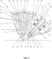
- Figures 1 and 2 show a coupling 10 for arrangement in a drive train between a driving element 1 and a driven element 2 as well as their common axis of rotation A.
- the driving element 1 may be a crankshaft of an engine or the like while the driven element 2 can be for example a gearbox.
- Each element 1 or 2 may be provided with a flange portion 3 and 4 for connection with the coupling 10 by means of fasteners 5 and 6 such as screws or the like.
- the coupling 10 comprises an outer housing 20 which is configured to be coupled to one of the driving element 1 and the driven element 2. In the embodiment shown the outer housing 20 is coupled to the driving element 1.
- the coupling 10 comprises a hub 30 arranged centrally within the outer housing 20.
- the hub 30 is configured to be coupled coaxially to the other of said driving element 1 and driven element 2, here the driven element 2 of said drive train.
- the hub 30 may be formed with a flange portion 31 for connection with the flange portion 4 of the driven element 2.
- the outer housing 20 and the hub 30 define an inner space 11 of the coupling 10 for enclosing an internal body 40.
- This inner space 11 is generally annular in shape and extends around the hub 30. Accordingly, the internal body 40 within said inner space 11 extends around the hub 30 and is movable relative to the outer housing 20 as well as to the hub 30 in circumferential direction C around the hub 30.
- the internal body 40 is encapsulated completely within said inner space 11 and thus has no portion exposed to the exteri or.
- the internal space 11 of the coupling 10 is filled with a damping medium 50 such as oil. Accordingly, the internal space 11 is sealed against the exterior by sealing means, for example two sealing rings 60 disposed between the outer housing 20 and the hub 30.
- Relative rotation in circumferential direction C between the outer housing 20 and the internal body 40 is delimited by a first set of leaf springs 70 while relative rotation in circumferential direction C between the hub 30 and the internal body 40 is delimited by a second set of leaf springs 80 which are arranged independently of and separately from the first set of leaf springs 70.
- the first and second leaf springs 70 and 80 are configured to deform elastically upon relative rotation between the outer housing 20 and internal body 40 and between the hub 30 and internal body 40.
- the first and second leaf springs 70 and 80 are arranged in dedicated first and second chambers 12 and 13 of the inner space 11.
- the first chambers 12 are formed between the outer housing 20 and the internal body 40 whereas the second chambers 13 are formed between the hub 30 and the internal body 40.
- the first chambers 12 and the second chambers 13 are provided separately from each other. They do not communicate with each other in circumferential direction C.
- the first chambers 12 may be substantially defined by outer pockets 41 at the outer circumference of the internal body 40 whereas the second chambers 13 may be substantially defined as inner pockets 42 at the inner circumference of the internal body 40.
- the outer pockets 41 open towards an inner wall 21 of the outer housing 20, i.e. a wall facing radially inwards, whereas the inner pockets 42 open in an opposite direction, i.e. radially inwardly towards an outer circumference of the hub 30.
- the first leaf springs 70 which are arranged in said first chambers 12, connect the outer housing 20 and the internal body 40. They extend radially inwardly from the outer housing 20 towards the internal body 40 and are configured to deform elastically upon relative rotation between the outer housing 20 and the internal body 40.
- the second leaf springs 80 arranged in said second chambers 13 connect the internal body 40 and the hub 30. They extend radially outwardly from the hub 30 towards the internal body 40 and are configured to deform elastically upon relative rotation between the hub 30 and the internal body 40.
- Figure 2 shows, merely by example, a pair of two leaf springs 70 and 80 in each chamber 12 and 13, respectively.
- the number of leaf springs per chamber may be smaller or larger than shown.
- the leaf springs 70 and 80 in each chamber 12 and 13 are spaced apart from each other to thereby reduce internal friction of the coupling 10.
- the leaf springs 70 and 80 each have a first end portion which is clampingly secured on one of the outer housing 20, the hub 30 and the internal body 40, e.g. clamped in a slot provided thereon, while the second opposite tip end portion loosely engages a groove for mainly supporting forces in circumferential direction C.
- the first leaf springs 70 are arranged in a way that their first end portions 71 are respectively clamped by corresponding slots 22 at the outer housing 20.
- the inner tip portions 72 of the first leaf springs 70 are respectively engaged with grooves 43 formed at the bottom 44 of the outer pockets 41 of the internal body 40.
- the second leaf springs 80 in the second chambers 13 may be clamped at their first outer end portions 81 by slots 45 formed at the top 46 of the inner pockets 42 of the internal body 40.
- Inner tip portions 82 of the second leaf springs 80 extend into grooves 32 formed at the outer circumference of the hub 30.
- damping medium in the first and second chambers 12 and 13 is displaced via corresponding oil gaps 14 and 15 connecting neighbouring first chambers 12 and connecting neighbouring second chambers 13, respectively.
- Figure 2 shows first oil gaps 14 formed between an inner wall 21 of the outer housing 20 facing radially inwardly and an outer wall 47 of the internal body 40 facing radially outwardly to thereby establish throttled fluid communication between two neighbouring first chambers 12 for providing hydraulic damping.
- the first oil gaps 14 stretch radially around the outside of the second chambers 13.
- second oil gaps 15 are provided between neighbouring second chambers 13.
- the second oil gaps 15 are formed between an inner wall 48 of the internal body 40 facing the radially inwardly and an outer wall 33 of the hub 30 facing radially outwardly to thereby establish throttled fluid communication between two neighbouring second chambers 13 for providing hydraulic damping.
- the second oil gaps 15 pass the first chambers 12 radially inwardly of the bottom 44 of the outer pockets 41.
- both damping systems are substantially independent of each other since the corresponding chambers 12 and 13 and oil gaps 14 and 15 are hydraulically isolated from each other. Accordingly, each damping system can be tuned individually. It is readily apparent from Figure 2 , that the pockets 41 and 42 of the internal body 40 are hydraulically separate from each other in circumferential direction C. In other words, the internal body 40 prevents leakage between the two damping systems. Moreover, the extended length of the oil gaps 14 and 15 is beneficial for damping.
- the outer housing 20 comprises an outer ring 23 for securing the outer end portions 71 of the first leaf springs 70.
- the outer ring 23 has interior protrusions 24 which are provided with the slots 22 for receiving the outer end portions 71 of the first leaf springs 70.
- the interior protrusions 24 may be integrally formed with the outer ring 23 or otherwise attached thereto.
- the outer diameter of the internal body 40 extends radially beyond the largest possible circle that can be drawn radially within the inner ends of said interior protrusions 24. In other words, the internal body 40 extends radially outwardly into a space between said interior protrusions 24.
- the lateral walls of the outer pockets 41 may be provided with recesses or cut-outs 49 in circumferential direction C for said interior protrusions 24 to thereby enlarge the maximum torsional displacement between the outer housing 20 and the internal body 40.
- the outer housing 20 includes two side walls 25 and 26 that abut the axial front faces of the outer ring 23.
- the side walls 25 and 26 may generally be formed as annular discs and are arranged opposite to each other to thereby laterally delimit the inner space 11 of the coupling 10. They may be secured against each other by means of fasteners 90 with the outer ring 23 being clamped between them.
- the side walls 25 and 26 are engaged with outer wall portions 34 of the inner hub 30 via the sealing rings 60.
- One of the side walls 25 is configured to be coupled to one of the driving element 1 and driven element 2, here the driving element 1.
- At least one of the side walls 25 and 26, here side wall 25 may optionally be formed as a flywheel of an engine, so that a separate flywheel may be dispensed with.
- the interior body 40 may be provided with substantial inertial mass so that the coupling 10 may operate as a dual mass flywheel.
- the mass of the interior body 40 may be designed sufficient for blocking or attenuating vibrations at acoustically relevant frequencies, in which case the coupling 10 will be particularly suitable for acoustically sensitive applications.
- the coupling 10 may operate as a very soft two-stage coupling with dedicated damping characteristics because of the two independent damping systems.
- the configuration as described above results in a very compact design that in addition reduces manufacturing expenses in respect of the sealing means required for sealing the inner chamber 11, which is filled with damping medium 50, against the exterior.
- the reduced number of dynamic sealings is also beneficial for reduced internal friction.
- the invention results in a single unitary device that is able to reduce torsional vibrations to an extremely low level unmatched in the art.
Landscapes
- Engineering & Computer Science (AREA)
- General Engineering & Computer Science (AREA)
- Physics & Mathematics (AREA)
- Acoustics & Sound (AREA)
- Aviation & Aerospace Engineering (AREA)
- Mechanical Engineering (AREA)
- Mechanical Operated Clutches (AREA)
Claims (13)
- Kupplung (10), umfassend:ein äußeres Gehäuse (20), das dazu konfiguriert ist, mit einem aus einem antreibenden Element (1) und einem angetriebenen Element (2) eines Antriebsstrangs gekoppelt zu werden,eine Nabe (30), die dazu konfiguriert ist, mit dem anderen aus dem antreibenden Element (1) und dem angetriebenen Element (2) des Antriebsstrangs gekoppelt zu werden,einen inneren Raum (11), der von dem äußeren Gehäuse (20) und der Nabe (30) umschlossen ist,einen inneren Körper (40), der in dem inneren Raum (11) angeordnet ist, sich um die Nabe (30) herum erstreckt und relativ zu dem äußeren Gehäuse (20) und der Nabe (30) in einer Umfangsrichtung um die Nabe (30) herum bewegbar ist,eine Vielzahl von ersten Kammern (12), die zwischen dem äußeren Gehäuse und dem inneren Körper (40) ausgebildet sind,eine Vielzahl von zweiten Kammern (13), die zwischen dem inneren Körper (40) und der Nabe (30) ausgebildet sind,erste Blattfedern (70), die in den ersten Kammern (12) angeordnet sind, wobei die ersten Blattfedern (70) das äußere Gehäuse (20) und den inneren Körper (40) verbinden und sich von dem äußeren Gehäuse (20) radial nach innen in Richtung des inneren Körpers (40) erstrecken und dazu konfiguriert sind, sich bei einer relativen Drehung zwischen dem äußeren Gehäuse (20) und dem inneren Körper (40) elastisch zu verformen,zweite Blattfedern (80), die in den zweiten Kammern (13) angeordnet sind, wobei die zweiten Blattfedern (80) den inneren Körper (40) und die Nabe (30) verbinden und sich von der Nabe (30) radial nach außen in Richtung des inneren Körpers (40) erstrecken und dazu konfiguriert sind, sich bei einer relativen Drehung zwischen der Nabe (30) und dem inneren Körper (40) elastisch zu verformen,erste Ölspalte (14), die zwischen einer radial nach innen weisenden inneren Wand (21) des äußeren Gehäuses (20) und einer radial nach außen weisenden äußeren Wand (47) des inneren Körpers (40) ausgebildet sind, wodurch eine gedrosselte Fluidverbindung zwischen benachbarten ersten Kammern (12) zur Bereitstellung einer hydraulischen Dämpfung hergestellt wird,zweite Ölspalte (15), die zwischen einer radial nach innen weisenden inneren Wand des inneren Körpers (40) und einer radial nach außen weisenden äußeren Wand der Nabe (30) ausgebildet sind, wodurch eine gedrosselte Fluidverbindung zwischen benachbarten zweiten Kammern (13) zur Bereitstellung einer hydraulischen Dämpfung hergestellt wird, unddadurch gekennzeichnet, dassdas äußere Gehäuse (20) mit inneren Vorsprüngen (24) versehen ist, die sich radial nach innen erstrecken, wobei die inneren Vorsprünge (24) dazu konfiguriert sind, äußere Endabschnitte (71) der ersten Blattfedern (70) klemmend zu befestigen, und dass sich der Außendurchmesser des inneren Körpers (40) radial über den größtmöglichen Kreis radial innerhalb der inneren Enden der inneren Vorsprünge (24) hinaus erstreckt.
- Kupplung (10) nach Anspruch 1, dadurch gekennzeichnet, dass die ersten Kammern (12) von den zweiten Kammern (13) hydraulisch getrennt sind.
- Kupplung (10) nach Anspruch 1 oder 2, dadurch gekennzeichnet, dass der innere Körper (40) mit äußeren Taschen (41) zum Definieren der ersten Kammern (12) und zum Aufnehmen der ersten Blattfedern (70) ausgebildet ist.
- Kupplung (10) nach Anspruch 3, dadurch gekennzeichnet, dass innere Spitzenabschnitte (72) der ersten Blattfedern (70) in Nuten (43) eingreifen, die am Boden (44) der äußeren Taschen (41) des inneren Körpers (40) ausgebildet sind.
- Kupplung (10) nach einem der Ansprüche 1 bis 4, dadurch gekennzeichnet, dass der innere Körper (40) mit inneren Taschen (42) zum Definieren der zweiten Kammern (13) und zum Aufnehmen der zweiten Blattfedern (80) ausgebildet ist.
- Kupplung (10) nach Anspruch 5, dadurch gekennzeichnet, dass äußere Endabschnitte (81) der zweiten Blattfedern (80) mit dem inneren Körper (40) verklemmt sind durch Schlitze (45), die an der Oberseite (46) der inneren Taschen (42) des inneren Körpers (40) ausgebildet sind.
- Kupplung (10) nach Anspruch 5 oder 6, dadurch gekennzeichnet, dass äußere Taschen (41) und innere Taschen (42) in Umfangsrichtung abwechselnd angeordnet und hydraulisch gegeneinander isoliert sind.
- Kupplung (10) nach einem der Ansprüche 1 bis 7, dadurch gekennzeichnet, dass das äußere Gehäuse (20) durch einen äußeren Ring (23) zur Befestigung der äußeren Endabschnitte (71) der ersten Blattfedern (70) und zwei mit dem äußeren Ring (23) verbundene und einander gegenüberliegend angeordnete Seitenwände (25, 26) zur seitlichen Begrenzung des inneren Raums (11) gebildet ist.
- Kupplung (10) nach einem der Ansprüche 1 bis 8, dadurch gekennzeichnet, dass die Seitenwände (25, 26) des äußeren Gehäuses (20) über Dichtungsringe (60) mit Außenwandabschnitten (34) der Nabe (30) in Eingriff stehen, um dadurch den inneren Raum (11) zu kapseln.
- Kupplung (10) nach einem der Ansprüche 1 bis 9, dadurch gekennzeichnet, dass mindestens eine der Seitenwände (25) des äußeren Gehäuses (20) ein Schwungrad bildet.
- Kupplung (10) nach einem der Ansprüche 1 bis 10, dadurch gekennzeichnet, dass eine der Seitenwände (25) des äußeren Gehäuses (20) dazu konfiguriert ist, mit einem aus einem antreibenden Element (1) und einem angetriebenen Element (2) des Antriebsstrangs gekoppelt zu werden.
- Kupplung (10) nach einem der Ansprüche 1 bis 11, dadurch gekennzeichnet, dass die Nabe (30) mit einem Flanschabschnitt (31) zur Verbindung mit einem aus dem antreibenden Element (1) und dem angetriebenen Element (2) des Antriebsstrangs ausgebildet ist.
- Kupplung (10) nach Anspruch 12, dadurch gekennzeichnet, dass die Seitenwände der äußeren Taschen (41) in Umfangsrichtung mit Aussparungen oder Ausschnitten (49) für die inneren Vorsprünge (24) versehen sind.
Priority Applications (1)
| Application Number | Priority Date | Filing Date | Title |
|---|---|---|---|
| EP19182297.2A EP3757420B1 (de) | 2019-06-25 | 2019-06-25 | Kopplung |
Applications Claiming Priority (1)
| Application Number | Priority Date | Filing Date | Title |
|---|---|---|---|
| EP19182297.2A EP3757420B1 (de) | 2019-06-25 | 2019-06-25 | Kopplung |
Publications (3)
| Publication Number | Publication Date |
|---|---|
| EP3757420A1 EP3757420A1 (de) | 2020-12-30 |
| EP3757420C0 EP3757420C0 (de) | 2024-09-25 |
| EP3757420B1 true EP3757420B1 (de) | 2024-09-25 |
Family
ID=67070635
Family Applications (1)
| Application Number | Title | Priority Date | Filing Date |
|---|---|---|---|
| EP19182297.2A Active EP3757420B1 (de) | 2019-06-25 | 2019-06-25 | Kopplung |
Country Status (1)
| Country | Link |
|---|---|
| EP (1) | EP3757420B1 (de) |
Families Citing this family (1)
| Publication number | Priority date | Publication date | Assignee | Title |
|---|---|---|---|---|
| CN112855849B (zh) * | 2021-03-15 | 2025-03-28 | 北京理工大学 | 一种转动关节用减震器及其减震方法 |
Family Cites Families (5)
| Publication number | Priority date | Publication date | Assignee | Title |
|---|---|---|---|---|
| DE3115788A1 (de) * | 1981-04-18 | 1982-11-04 | Hackforth GmbH & Co KG, 4690 Herne | Wellenkupplung mit elastischem zwischenring |
| US8834027B2 (en) * | 2011-01-13 | 2014-09-16 | Fouad Y. Zeidan | Damper having modular flexible ligaments and variable gaps |
| AT410829B (de) | 2001-10-22 | 2003-08-25 | Ellergon Antriebstech Gmbh | Antriebstrang mit einem drehschwingungsdämpfer und einer drehelastischen kupplung |
| DE102009004252B4 (de) | 2009-01-07 | 2012-11-15 | Ellergon Antriebstechnik Gmbh | Drehschwingungsdämpfer |
| DE102012110289A1 (de) | 2012-10-26 | 2014-04-30 | Ellergon Antriebstechnik Gesellschaft M.B.H. | Drehelastische Kupplung |
-
2019
- 2019-06-25 EP EP19182297.2A patent/EP3757420B1/de active Active
Also Published As
| Publication number | Publication date |
|---|---|
| EP3757420C0 (de) | 2024-09-25 |
| EP3757420A1 (de) | 2020-12-30 |
Similar Documents
| Publication | Publication Date | Title |
|---|---|---|
| US7121392B2 (en) | Hydraulic double clutch | |
| US7025681B2 (en) | Drive train with a torsional vibration damper and a torsionally flexible coupling | |
| US6112869A (en) | Force transmitting apparatus having an external damper | |
| US4944712A (en) | Split flywheel with vibration compensation between vehicle engine and drive train | |
| US9958027B2 (en) | Vibration damping device | |
| US5125872A (en) | Apparatus for damping torsional vibrations with a slip clutch between input and output members | |
| KR960015419B1 (ko) | 탄성 커플링 | |
| KR101366107B1 (ko) | 축진동 유압식 진동 댐퍼 겸용 유연 커플링 | |
| KR101264915B1 (ko) | 크랭크축에 연결된 비틀림 진동 댐퍼 및 상기 비틀림 진동댐퍼와 클러치의 결합체 | |
| CN102282383B (zh) | 设有扭转振动阻尼器的离合器装置 | |
| US5415061A (en) | Flywheel for power transmission system having equiangularly spaced dashpots | |
| US4874074A (en) | Torsional vibration damping mechanism | |
| EP2206934B1 (de) | Drehschwingungsdämpfer bzw. drehelastische Kupplung | |
| US4925409A (en) | Torsional damper for marine drive unit | |
| US5433666A (en) | Torsion damping device with a dynamic vibration damper, in particular for automotive vehicles | |
| US8056686B2 (en) | Torque converter with cover plate directly attached to piston | |
| US5503595A (en) | Torsion damping device for a motor vehicle, being in particular a double damped flywheel or a clutch friction wheel | |
| US20080006502A1 (en) | Clutch arrangement for the drive train of a vehicle | |
| GB2231937A (en) | Device for clamping vibrations | |
| US5083981A (en) | Two-mass fly-wheel for a motor vehicle | |
| US20050087420A1 (en) | Powertrain | |
| CN107850180A (zh) | 离心力摆和具有离心力摆的液力变矩器 | |
| EP3757420B1 (de) | Kopplung | |
| US20100000833A1 (en) | Rotational vibration damper | |
| US5769195A (en) | Lock-up clutch for a torque convertor |
Legal Events
| Date | Code | Title | Description |
|---|---|---|---|
| PUAI | Public reference made under article 153(3) epc to a published international application that has entered the european phase |
Free format text: ORIGINAL CODE: 0009012 |
|
| STAA | Information on the status of an ep patent application or granted ep patent |
Free format text: STATUS: THE APPLICATION HAS BEEN PUBLISHED |
|
| AK | Designated contracting states |
Kind code of ref document: A1 Designated state(s): AL AT BE BG CH CY CZ DE DK EE ES FI FR GB GR HR HU IE IS IT LI LT LU LV MC MK MT NL NO PL PT RO RS SE SI SK SM TR |
|
| AX | Request for extension of the european patent |
Extension state: BA ME |
|
| STAA | Information on the status of an ep patent application or granted ep patent |
Free format text: STATUS: REQUEST FOR EXAMINATION WAS MADE |
|
| 17P | Request for examination filed |
Effective date: 20210630 |
|
| RBV | Designated contracting states (corrected) |
Designated state(s): AL AT BE BG CH CY CZ DE DK EE ES FI FR GB GR HR HU IE IS IT LI LT LU LV MC MK MT NL NO PL PT RO RS SE SI SK SM TR |
|
| RAP3 | Party data changed (applicant data changed or rights of an application transferred) |
Owner name: GEISLINGER GROUP GMBH |
|
| GRAP | Despatch of communication of intention to grant a patent |
Free format text: ORIGINAL CODE: EPIDOSNIGR1 |
|
| STAA | Information on the status of an ep patent application or granted ep patent |
Free format text: STATUS: GRANT OF PATENT IS INTENDED |
|
| INTG | Intention to grant announced |
Effective date: 20240423 |
|
| GRAS | Grant fee paid |
Free format text: ORIGINAL CODE: EPIDOSNIGR3 |
|
| GRAA | (expected) grant |
Free format text: ORIGINAL CODE: 0009210 |
|
| STAA | Information on the status of an ep patent application or granted ep patent |
Free format text: STATUS: THE PATENT HAS BEEN GRANTED |
|
| AK | Designated contracting states |
Kind code of ref document: B1 Designated state(s): AL AT BE BG CH CY CZ DE DK EE ES FI FR GB GR HR HU IE IS IT LI LT LU LV MC MK MT NL NO PL PT RO RS SE SI SK SM TR |
|
| REG | Reference to a national code |
Ref country code: GB Ref legal event code: FG4D |
|
| REG | Reference to a national code |
Ref country code: CH Ref legal event code: EP |
|
| REG | Reference to a national code |
Ref country code: DE Ref legal event code: R096 Ref document number: 602019059358 Country of ref document: DE |
|
| REG | Reference to a national code |
Ref country code: IE Ref legal event code: FG4D |
|
| U01 | Request for unitary effect filed |
Effective date: 20241010 |
|
| U07 | Unitary effect registered |
Designated state(s): AT BE BG DE DK EE FI FR IT LT LU LV MT NL PT RO SE SI Effective date: 20241030 |
|
| PG25 | Lapsed in a contracting state [announced via postgrant information from national office to epo] |
Ref country code: NO Free format text: LAPSE BECAUSE OF FAILURE TO SUBMIT A TRANSLATION OF THE DESCRIPTION OR TO PAY THE FEE WITHIN THE PRESCRIBED TIME-LIMIT Effective date: 20241225 |
|
| PG25 | Lapsed in a contracting state [announced via postgrant information from national office to epo] |
Ref country code: GR Free format text: LAPSE BECAUSE OF FAILURE TO SUBMIT A TRANSLATION OF THE DESCRIPTION OR TO PAY THE FEE WITHIN THE PRESCRIBED TIME-LIMIT Effective date: 20241226 |
|
| PG25 | Lapsed in a contracting state [announced via postgrant information from national office to epo] |
Ref country code: RS Free format text: LAPSE BECAUSE OF FAILURE TO SUBMIT A TRANSLATION OF THE DESCRIPTION OR TO PAY THE FEE WITHIN THE PRESCRIBED TIME-LIMIT Effective date: 20241225 |
|
| PG25 | Lapsed in a contracting state [announced via postgrant information from national office to epo] |
Ref country code: RS Free format text: LAPSE BECAUSE OF FAILURE TO SUBMIT A TRANSLATION OF THE DESCRIPTION OR TO PAY THE FEE WITHIN THE PRESCRIBED TIME-LIMIT Effective date: 20241225 Ref country code: NO Free format text: LAPSE BECAUSE OF FAILURE TO SUBMIT A TRANSLATION OF THE DESCRIPTION OR TO PAY THE FEE WITHIN THE PRESCRIBED TIME-LIMIT Effective date: 20241225 Ref country code: GR Free format text: LAPSE BECAUSE OF FAILURE TO SUBMIT A TRANSLATION OF THE DESCRIPTION OR TO PAY THE FEE WITHIN THE PRESCRIBED TIME-LIMIT Effective date: 20241226 |
|
| PG25 | Lapsed in a contracting state [announced via postgrant information from national office to epo] |
Ref country code: IS Free format text: LAPSE BECAUSE OF FAILURE TO SUBMIT A TRANSLATION OF THE DESCRIPTION OR TO PAY THE FEE WITHIN THE PRESCRIBED TIME-LIMIT Effective date: 20250125 |
|
| PG25 | Lapsed in a contracting state [announced via postgrant information from national office to epo] |
Ref country code: SM Free format text: LAPSE BECAUSE OF FAILURE TO SUBMIT A TRANSLATION OF THE DESCRIPTION OR TO PAY THE FEE WITHIN THE PRESCRIBED TIME-LIMIT Effective date: 20240925 |
|
| PG25 | Lapsed in a contracting state [announced via postgrant information from national office to epo] |
Ref country code: ES Free format text: LAPSE BECAUSE OF FAILURE TO SUBMIT A TRANSLATION OF THE DESCRIPTION OR TO PAY THE FEE WITHIN THE PRESCRIBED TIME-LIMIT Effective date: 20240925 |
|
| PG25 | Lapsed in a contracting state [announced via postgrant information from national office to epo] |
Ref country code: PL Free format text: LAPSE BECAUSE OF FAILURE TO SUBMIT A TRANSLATION OF THE DESCRIPTION OR TO PAY THE FEE WITHIN THE PRESCRIBED TIME-LIMIT Effective date: 20240925 Ref country code: CZ Free format text: LAPSE BECAUSE OF FAILURE TO SUBMIT A TRANSLATION OF THE DESCRIPTION OR TO PAY THE FEE WITHIN THE PRESCRIBED TIME-LIMIT Effective date: 20240925 |
|
| PG25 | Lapsed in a contracting state [announced via postgrant information from national office to epo] |
Ref country code: SK Free format text: LAPSE BECAUSE OF FAILURE TO SUBMIT A TRANSLATION OF THE DESCRIPTION OR TO PAY THE FEE WITHIN THE PRESCRIBED TIME-LIMIT Effective date: 20240925 |
|
| PLBE | No opposition filed within time limit |
Free format text: ORIGINAL CODE: 0009261 |
|
| STAA | Information on the status of an ep patent application or granted ep patent |
Free format text: STATUS: NO OPPOSITION FILED WITHIN TIME LIMIT |
|
| U20 | Renewal fee for the european patent with unitary effect paid |
Year of fee payment: 7 Effective date: 20250627 |
|
| 26N | No opposition filed |
Effective date: 20250626 |