EP3757409B1 - Öffnungs- und schliessmechanismus und elektronische vorrichtung - Google Patents
Öffnungs- und schliessmechanismus und elektronische vorrichtung Download PDFInfo
- Publication number
- EP3757409B1 EP3757409B1 EP18915360.4A EP18915360A EP3757409B1 EP 3757409 B1 EP3757409 B1 EP 3757409B1 EP 18915360 A EP18915360 A EP 18915360A EP 3757409 B1 EP3757409 B1 EP 3757409B1
- Authority
- EP
- European Patent Office
- Prior art keywords
- rotating shaft
- opening
- sliding
- body fastening
- interference
- Prior art date
- Legal status (The legal status is an assumption and is not a legal conclusion. Google has not performed a legal analysis and makes no representation as to the accuracy of the status listed.)
- Active
Links
Images


Classifications
-
- G—PHYSICS
- G06—COMPUTING OR CALCULATING; COUNTING
- G06F—ELECTRIC DIGITAL DATA PROCESSING
- G06F1/00—Details not covered by groups G06F3/00 - G06F13/00 and G06F21/00
- G06F1/16—Constructional details or arrangements
- G06F1/1613—Constructional details or arrangements for portable computers
- G06F1/1615—Constructional details or arrangements for portable computers with several enclosures having relative motions, each enclosure supporting at least one I/O or computing function
- G06F1/1616—Constructional details or arrangements for portable computers with several enclosures having relative motions, each enclosure supporting at least one I/O or computing function with folding flat displays, e.g. laptop computers or notebooks having a clamshell configuration, with body parts pivoting to an open position around an axis parallel to the plane they define in closed position
- G06F1/1618—Constructional details or arrangements for portable computers with several enclosures having relative motions, each enclosure supporting at least one I/O or computing function with folding flat displays, e.g. laptop computers or notebooks having a clamshell configuration, with body parts pivoting to an open position around an axis parallel to the plane they define in closed position the display being foldable up to the back of the other housing with a single degree of freedom, e.g. by 360° rotation over the axis defined by the rear edge of the base enclosure
-
- G—PHYSICS
- G06—COMPUTING OR CALCULATING; COUNTING
- G06F—ELECTRIC DIGITAL DATA PROCESSING
- G06F1/00—Details not covered by groups G06F3/00 - G06F13/00 and G06F21/00
- G06F1/16—Constructional details or arrangements
- G06F1/1613—Constructional details or arrangements for portable computers
- G06F1/1633—Constructional details or arrangements of portable computers not specific to the type of enclosures covered by groups G06F1/1615 - G06F1/1626
- G06F1/1675—Miscellaneous details related to the relative movement between the different enclosures or enclosure parts
- G06F1/1681—Details related solely to hinges
-
- E—FIXED CONSTRUCTIONS
- E05—LOCKS; KEYS; WINDOW OR DOOR FITTINGS; SAFES
- E05D—HINGES OR SUSPENSION DEVICES FOR DOORS, WINDOWS OR WINGS
- E05D11/00—Additional features or accessories of hinges
-
- E—FIXED CONSTRUCTIONS
- E05—LOCKS; KEYS; WINDOW OR DOOR FITTINGS; SAFES
- E05D—HINGES OR SUSPENSION DEVICES FOR DOORS, WINDOWS OR WINGS
- E05D3/00—Hinges with pins
- E05D3/06—Hinges with pins with two or more pins
- E05D3/12—Hinges with pins with two or more pins with two parallel pins and one arm
-
- E—FIXED CONSTRUCTIONS
- E05—LOCKS; KEYS; WINDOW OR DOOR FITTINGS; SAFES
- E05D—HINGES OR SUSPENSION DEVICES FOR DOORS, WINDOWS OR WINGS
- E05D7/00—Hinges or pivots of special construction
- E05D7/0009—Adjustable hinges
-
- E—FIXED CONSTRUCTIONS
- E05—LOCKS; KEYS; WINDOW OR DOOR FITTINGS; SAFES
- E05Y—INDEXING SCHEME ASSOCIATED WITH SUBCLASSES E05D AND E05F, RELATING TO CONSTRUCTION ELEMENTS, ELECTRIC CONTROL, POWER SUPPLY, POWER SIGNAL OR TRANSMISSION, USER INTERFACES, MOUNTING OR COUPLING, DETAILS, ACCESSORIES, AUXILIARY OPERATIONS NOT OTHERWISE PROVIDED FOR, APPLICATION THEREOF
- E05Y2999/00—Subject-matter not otherwise provided for in this subclass
Definitions
- Embodiments of this invention relate to the field of notebook computer structures, and in particular, to an opening and closing mechanism and an electronic device.
- the dual-screen notebook computer has two liquid crystal displays (Liquid Crystal Display, LCD) and one rotating shaft structure, and the two LCDs are connected by using the rotating shaft structure of the notebook computer, to open and close the notebook computer.
- At least one of the two LCDs has a touch function, and the LCD having the touch function may be used as a keyboard, so that the user can implement external input through a touch operation.
- LCD Liquid Crystal Display
- the LCD having the touch function may be used as a keyboard, so that the user can implement external input through a touch operation.
- a current dual-screen notebook computer when two LCDs are used as screens for display, it is necessary to ensure that there is no gap between the two LCDs when the two LCDs are disposed side by side.
- a rotating shaft structure that is of the dual-screen notebook computer and that meets the foregoing requirement is usually disposed on a rear side of the LCD, and an opening and closing angle can reach only 200°, which cannot meet a 360° opening and closing requirement of the user.
- a dual-screen notebook computer that meets the 360° opening and closing requirement there is a relatively large gap between two LCDs when the two LCDs are disposed side by side, and full-screen experience cannot be provided for a user.
- EP 2 829 945 A2 describes a display device that includes a hinge module comprising a pair of hinge shafts arranged side by side, a pair of hinge brackets having one ends coupled to the hinge shafts, respectively, and the other ends in which slide slots are formed, a pair of slide brackets coupled to the slide slots, the slide brackets which are horizontally movable along the slide slots, and a pair of bodies coupled to the slide brackets, respectively, such that the display device may be foldable 0 ⁇ 180 degrees to be folded and unfolded like a book.
- US 2018/0066465 A1 describes a device having include a first portion and a second portion. The first portion can define a first hinge axis and can be resiliently biased toward the first hinge axis.
- the second portion can define a second hinge axis and can be resiliently biased toward the second hinge axis.
- a first cam can operate relative to the first hinge axis and is slidably secured to the first portion.
- a second cam can operate relative to the second hinge axis and can be slidably secured to the first portion. When the first and second portions are oriented at an acute angle the second cam can force the second portion away from the second hinge axis while the first cam can allow the first portion to remain biased toward the first hinge axis.
- CN 206 918 043 U describes the realization of syntropy rotation portion is passed through at collapsible terminal the symmetry at collapsible terminal opens and shuts, and passesthrough syntropy rotation portion drives the motion of triangle connecting rod rotation portion, realizes collapsible terminal folding in -process, along with the change of the angle that opens and shuts at collapsible terminal and appearing collapsible terminal the same adaptive length that the distance at pivot to its two edges appears simultaneously changes, makes coaxial rotation portion is located all the time the intermediate position at collapsible terminal, thus prevent the skew of coaxial rotation portion.
- US 2009/075702 A1 describes an electronic device that includes at least two display casings each having a display therein, a connecting member comprising two rotation shafts arranged in parallel to each other and coupled to respective ones of the two display casings so as to allow each of the two display casings to rotate, and a sliding mechanism configured to allow the two display casings to move toward each other so as to allow the displays of the two display casings to form a single larger display area.
- Embodiments of this invention provide an opening and closing mechanism and an electronic device, to implement that there is no gap between two bodies of the electronic device when the electronic device is opened and closed at 360° and when the electronic device is opened and closed at 180°.
- the invention is defined by the appended independent claims, wherein preferred embodiments are defined in the dependent claims.
- the first body fastening part slides toward the first rotating shaft, and the second body fastening part slides toward the second rotating shaft.
- the opening and closing angle is 180°, there is no gap or a small gap between the first body and the second body, the rotating shaft is invisible on the display screen side, and the two display screens are one display screen in a visual effect. This improves user experience.
- the opening and closing angle is changed from 180° to 360°, the distance between the first body fastening part and the first rotating shaft remains unchanged, and the distance between the second body fastening part and the second rotating shaft remains unchanged.
- the rotating shaft is accommodated in a body of the electronic device.
- the opening and closing angle is changed from 180° to 0°, the first body fastening part slides away from the first rotating shaft, and the second body fastening part slides away from the second rotating shaft, to avoid interference between the first body and the second body, avoid interference caused by the rotating shaft to the first body and the second body, and implement 360° opening and closing between the first body and the second body.
- inventions of this application provides an opening and closing mechanism.
- the opening and closing mechanism may fasten two bodies of an electronic device. In this way, the two bodies of the electronic device can be opened and closed at 360°, and when an opening and closing angle between the two bodies is 180°, it is ensured that there is no gap between the two bodies or the gap is small enough.
- the opening and closing mechanism includes a first rotating shaft and a second rotating shaft that are disposed in parallel, a first telescopic part disposed on the first rotating shaft, and a second telescopic part disposed on the second rotating shaft.
- the first rotating shaft and the second rotating shaft are rotationally connected.
- the first rotating shaft and the second rotating shaft may be rotationally connected by using a chain, a hinge, a rope, a sleeve, or the like. Any implementation in which the first rotating shaft and the second rotating shaft can be rotationally connected may be applied to the embodiments of this application.
- the first telescopic part includes a first connection part connected to the first rotating shaft and a first body fastening part configured to slide along the first connection part, and the first body fastening part is configured to fasten a first body of the electronic device.
- the first body fastening part may fasten the first body in a manner such as adhesive bonding, fastening, or threaded connection.
- a specific fastening manner is not specially limited in this embodiment.
- the second telescopic part includes a second connection part connected to the second rotating shaft and a second body fastening part configured to slide along the second connection part, and the second body fastening part is configured to fasten a second body of the electronic device.
- the second body fastening part may fasten the second body in a manner such as adhesive bonding, fastening, or threaded connection.
- a specific fastening manner is not specially limited in this embodiment.
- the electronic device may be any device having a flipping function, for example, a notebook computer, a flip phone, or a navigator.
- a flipping function for example, a notebook computer, a flip phone, or a navigator.
- the flipping in this embodiment means that the first body and the second body may be closed at 0°, or may be opened at various angles, for example, 90°, 180°, 270°, and 360°.
- an angle between the first body and the second body may be equal to an angle between the first body fastening part and the second body fastening part, or may be equal to a difference between 360° and an angle between the first body fastening part and the second body fastening part.
- the first body fastening part and the second body fastening part are used as a reference.
- the angle between the first body fastening part and the second body fastening part is 0°
- the first body and the second body may be disposed face to face, and the angle between the first body and the second body is 0°.
- the first body and the second body may be disposed back to back, and the angle between the first body and the second body is 360°.
- the electronic device is a notebook computer
- the first body is a first display screen
- the second body is a second display screen
- an angle between the first display screen and the second display screen is equal to the angle between the first body fastening part and the second body fastening part is used for description.
- an opening and closing angle between the first body fastening part and the second body fastening part when an opening and closing angle between the first body fastening part and the second body fastening part is 0°, there is a gap between the first body fastening part and the first rotating shaft, and there is a gap between the second body fastening part and the second rotating shaft.
- the opening and closing angle is changed from 0° to 180°, the first body fastening part slides toward the first rotating shaft, the second body fastening part slides toward the second rotating shaft.
- the opening and closing angle is 180° and the first display screen and the second display screen are disposed side by side, there is no gap between the first body fastening part and the first rotating shaft, and there is no gap between the second body fastening part and the second rotating shaft. In this way, there is no gap or a small gap between the first display screen and the second display screen, and the rotating shaft is invisible on a display screen side.
- a person skilled in the art may understand that, in a process in which the opening and closing angle is changed from 180° to 0°, the display screen is closed inward, the first body fastening part slides away from the first rotating shaft, and the second body fastening part slides away from the second rotating shaft, to avoid interference between the first display screen and the second display screen when the opening and closing angle is 0°, avoid interference caused by the rotating shaft to the first display screen and the second display screen, and implement 360° opening and closing between the first display screen and the second display screen.
- the first telescopic part further includes a first sliding part that is slidingly connected to the first connection part, and the first sliding part is configured to slide along the first connection part, to drive the first body fastening part to slide along the first connection part.
- the second telescopic part further includes a second sliding part that is slidingly connected to the second connection part, and the second sliding part is configured to slide along the second connection part, to drive the second body fastening part to slide along the second connection part.
- the first body fastening part is configured to slide by using the first sliding part.
- the first sliding part is slidingly connected to the first connection part.
- the second body fastening part is configured to slide by using the second sliding part.
- the second sliding part is slidingly connected to the second connection part.
- the first connection part includes a first interference part sleeved on the first rotating shaft and a first supporting part connected to the first interference part, and the first body fastening part may slide along the first supporting part.
- the second connection part includes a second interference part sleeved on the second rotating shaft and a second supporting part connected to the second interference part, and the first body fastening part may slide along the second supporting part.
- the first interference part and the second interference part are in an interference state, so that the first rotating shaft and the second rotating shaft generate a torsion force, and if there is no external force, the first display screen and the second display screen may keep stable at any angle from 0° to 180°. This avoids relative rotation of the first rotating shaft and the second rotating shaft.
- the opening and closing mechanism provided in this embodiment includes: the first rotating shaft and the second rotating shaft that are disposed in parallel, the first telescopic part disposed on the first rotating shaft and the second telescopic part disposed on the second rotating shaft, and the first rotating shaft and the second rotating shaft are rotationally connected.
- the first telescopic part includes the first connection part connected to the first rotating shaft and the first body fastening part that is configured to slide along the first connection part, and the first body fastening part is configured to fasten the first display screen.
- the second telescopic part includes the second connection part connected to the second rotating shaft and the second body fastening part that is configured to slide along the second connection part, and the second body fastening part is configured to fasten the second display screen.
- the first body fastening part slides toward the first rotating shaft, and the second body fastening part slides toward the second rotating shaft.
- the opening and closing angle is 180°, there is no gap or a small gap between the first display screen and the second display screen, the rotating shaft is invisible on the display screen side, and the two display screens are one display screen in a visual effect. This improves user experience.
- the opening and closing angle is changed from 180° to 360°, the distance between the first body fastening part and the first rotating shaft remains unchanged, and the distance between the second body fastening part and the second rotating shaft remains unchanged.
- the rotating shaft is accommodated in a body of the electronic device.
- the opening and closing angle is changed from 180° to 0°, the first body fastening part slides away from the first rotating shaft, and the second body fastening part slides away from the second rotating shaft, to avoid interference between the first display screen and the second display screen, avoid interference caused by the rotating shaft to the first display screen and the second display screen, and implement 360° opening and closing between the first display screen and the second display screen.
- opening and closing mechanism may be implemented by using a plurality of structures.
- Other structures that may be implemented by using the principles of this embodiment all fall within the protection scope of the appendend claims. Details are not described herein again in this embodiment.
- FIG. 1 is a schematic diagram of an entire mechanism of an opening and closing mechanism according to Embodiment 1 of the invention.
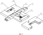
- FIG. 2 is a schematic exploded diagram 1 of an opening and closing mechanism according to Embodiment 1
- FIG. 3 is a schematic exploded diagram 2 of an opening and closing mechanism according to Embodiment 1.
- the opening and closing mechanism includes a first rotating shaft 11 and a second rotating shaft 12 that are disposed in parallel, a first telescopic part 13 disposed on the first rotating shaft 11, and a second telescopic part 14 disposed on the second rotating shaft 12.
- the first rotating shaft 11 and the second rotating shaft 12 are rotationally connected.
- the first telescopic part 13 includes a first connection part 131 connected to the first rotating shaft 11 and a first body fastening part 132 that may slide along the first connection part 131, and the first body fastening part 132 is configured to fasten a first display screen.
- the second telescopic part 14 includes a second connection part 141 connected to the second rotating shaft 12 and a second body fastening part 142 that may slide along the second connection part 141, and the second body fastening part 142 is configured to fasten a second display screen.
- the first body fastening part 132 is a housing structure, the first body fastening part 132 is sleeved outside the first connection part 131, the first body fastening part 142 is a housing structure, and the first body fastening part 142 is sleeved outside the second connection part 141.
- the opening and closing angle is changed from 0° to 180°
- the first body fastening part 132 slides toward the first rotating shaft 11
- the second body fastening part 142 slides toward the second rotating shaft 12.
- the opening and closing angle is changed from 180° to 360°
- a distance between the first body fastening part 132 and the first rotating shaft 11 remains unchanged
- a distance between the second body fastening part 142 and the second rotating shaft 12 remains unchanged
- the opening and closing angle is an angle between the first body fastening part 132 and the second body fastening part 142.
- the first telescopic part 13 further includes a first sliding part 133 that is slidingly connected to the first connection part 131, the first sliding part 133 may slide along the first connection part 131, to drive the first body fastening part 132 to slide along the first connection part 131.
- a structure of the second telescopic part 14 is the same as a structure of the first telescopic part 13. Details are not described herein again in this embodiment.
- a structure of the first rotating shaft is the same as a structure of the second rotating shaft
- the structure of the first telescopic part is the same as the structure of the second telescopic part. Therefore, this embodiment is described by using the first rotating shaft and the first telescopic part as an example, and structures of the second rotating shaft and the second telescopic part are not described in detail again.
- FIG. 4 is a schematic diagram of a sliding structure according to Embodiment 1 of this application.
- FIG. 5 is a schematic structural diagram of a sliding shaft according to Embodiment 1.
- FIG. 6A, FIG. 6B and FIG. 6C are schematic sliding diagrams of a body fastening part according to an embodiment of this application.
- FIG. 7 is a schematic diagram of an elastic structure according to Embodiment 1 of this application.
- FIG. 8 is a schematic structural diagram of a body fastening part according to Embodiment 1.
- a sliding shaft 111 is disposed on an outer circumferential surface of the first rotating shaft 11
- a sliding groove 1111 is disposed on the sliding shaft 111
- the first sliding part 133 may slide around the sliding groove 1111, so that the first sliding part 133 slides along the first connection part 131, to drive the first body fastening part 132 to slide along the first connection part 131.
- the sliding groove 1111 includes an inclined groove 1111A and a straight groove 1111B that are connected, and a sliding point 1331 is disposed on a first side surface of the first sliding part 133.
- the sliding point 1331 is disposed on the first side surface, the first side surface may be an arc-shaped surface matching the first rotating shaft 11, and the sliding point 1331 protrudes from the first side surface. In this way, when the first side surface is fitted to the outer circumferential surface of the first rotating shaft 11, the sliding point 1331 may be located in the sliding groove 1111.
- the sliding point 1331 may be a protrusion of various shapes, for example, may be a spherical protrusion, a hemispherical protrusion, or a spherical cap protrusion. A shape of the sliding point 1331 is not particularly limited in this embodiment.
- the sliding point 1331 slides in the inclined groove 1111A, so that the first sliding part 133 slides along the first connection part 131.
- the inclined groove 1111A is inclined, when the sliding point 1331 slides in the inclined groove 1111A, the first sliding part 133 slides on the first connection part 131 along a direction parallel to the first rotating shaft 11.
- the sliding point 1331 may slide in the straight groove 1111B, so that the first sliding part 133 and the first connection part 131 are relatively stationary. Specifically, when the sliding point 1331 slides in the straight groove 1111B, no displacement occurs along the direction parallel to the first rotating shaft 11. Therefore, no displacement change occurs between the first sliding part 133 and the first connection part 131.
- a groove 1332 is disposed on a second side surface of the first sliding part 133.
- the second side surface is disposed opposite to the first side surface.
- the groove 1332 may be clamped outside the first connection part 131, and the groove 1332 may slide along the first connection part 131.
- the groove 1332 is disposed, so that the first sliding part 133 and the first connection part 131 form a clamping function. This makes the sliding smooth, and avoids that the first sliding part is deviated or detached from the first connection part.
- an inclined body 1333 is disposed on a surface of the first sliding part 133, and a sliding opening 1321 matching the inclined body 1333 is disposed on the first body fastening part 132.
- the sliding opening 1321 slides along the inclined body 1333.
- the sliding opening 1321 and the inclined body 1333 are relatively stationary.
- FIG. 6A a relative position between the first sliding part 133 and the first body fastening part 132 may be shown in FIG. 6A .
- the sliding opening 1321 and the inclined body 1333 are relatively stationary, in other words, they keep in a state shown in FIG. 6A .
- the sliding point 1331 slides in the inclined groove 1111A.
- the sliding opening 1321 may slide along the inclined body 1333, to drive the first body fastening part 132 to slide away from the first rotating shaft 11, and a sliding direction is perpendicular to the first rotating shaft 11.
- a sliding process of the first body fastening part 132 is successively shown in FIG. 6A, FIG. 6B, and FIG. 6C .
- the first body fastening part 132 slides away from the first rotating shaft 11. In a process in which the opening and closing angle is changed from 0° to 180°, the first body fastening part 132 slides toward the first rotating shaft 11 and is reset. In this embodiment, the first body fastening part 132 may be reset by using an elastic component. The following provides detailed description with reference to FIG. 2 , FIG. 3 , FIG. 7 , and FIG. 8 .
- the first telescopic part 13 further includes an elastic component 134 and a position-limiting part 135.
- the position-limiting part 135 is disposed at one end that is of the first connection part 131 and that is away from the first rotating shaft 11.
- the position-limiting part 135 may be integrated with the first connection part 131 as a whole, or may be fastened to the first connection part 131 by bonding, welding, clamping, threaded connection, or the like. In other words, positions of the position-limiting part 135 and the first connection part 131 do not change.
- the elastic component 134 may be a spring, elastic silicone, an elastic structure, or the like. A specific implementation structure of the elastic component 134 is not particularly limited in this embodiment.
- An accommodation part 1313 is disposed on the first connection part 131, the elastic component may be disposed in the accommodation part 1313, one end of the elastic component 134 presses against the first body fastening part 132, and the other end of the elastic component 134 presses against the position-limiting part 135.
- the elastic component 134 may also be connected to the first body fastening part 132 and the position-limiting part 135.
- An implementation of disposing the elastic component 134 between the first body fastening part 132 and the position-limiting part 135 is not specially limited in this embodiment, provided that the elastic component 134 can be fastened between the first body fastening part 132 and the position-limiting part 135 and can be extended and contracted.
- a first circular groove 1352 is disposed on the position-limiting part 135, and one end of the elastic component 134 may be disposed in the first circular groove 1352.
- a second circular groove 1322 is disposed on the first body fastening part 132, and the other end of the elastic component 134 may be disposed in the second circular groove 1322.
- the elastic component 134 may be fastened by disposing the first circular groove 1352 and the second circular groove 1322, to prevent the elastic component 134 from being detached in an extension and contraction process.
- the first body fastening part 132 slides away from the first rotating shaft 11. Because a position of the position-limiting part 135 remains unchanged, the elastic component 134 is squeezed, and a length of the elastic component 134 is shortened. In a process in which the opening and closing angle is changed from 0° to 180°, the squeezed elastic component 134 performs a reset operation, to pull the first body fastening part 132 back from a position away from the first rotating shaft 11 to a position close to the first rotating shaft 11.
- a position-limiting step 1351 is disposed on a side surface of the position-limiting part 135.
- the opening and closing angle is 0°
- a part of the first body fastening part 132 presses against the position-limiting step 1351.
- the position-limiting step 1351 may limit the first body fastening part 132.
- the first body fastening part 132 presses against the position-limiting step 1351, the first body fastening part 132 stops sliding.
- FIG. 9 is a schematic diagram of an interference structure according to Embodiment 1 of this application.
- FIG. 10 is a front view of an interference structure according to Embodiment 1.
- the first connection part 131 includes a first interference part 1311 sleeved on the first rotating shaft 11 and a first supporting part 1312 connected to the first interference part 1311, and the first body fastening part 132 may slide along the first supporting part 1312.
- the second connection part 141 includes a second interference part 1411 sleeved on the second rotating shaft 12 and a second supporting part 1412 connected to the second interference part 1411, and the first body fastening part 132 may slide along the second supporting part 1412. In a process in which the opening and closing angle is changed from 0° to 180°, the first interference part 1311 and the second interference part 1411 are in an interference state.
- an interference effect between the first interference part 1311 and the second interference part 1411 causes a torsion force effect between the first rotating shaft and the second rotating shaft.
- the first interference part 1311 is a C-shaped interference part.
- the C-shaped interference part has an opening.
- FIG. 10 When the opening and closing angle is 180°, structures of the first interference part 1311 and the second interference part 1411 are shown in FIG. 10 .
- An upper part of the first interference part 1311 and an upper part of the second interference part 1411 have protruding parts.
- the first interference part 1311 and the second interference part 1411 are fitted.
- the first interference part 1311 interferes with the second interference part 1411, so that the first rotating shaft and the second rotating shaft generate the torsion force.
- the opening and closing angle between the first display screen and the second display screen may remain unchanged.
- the opening and closing mechanism further includes a joint part 15, a part of the first rotating shaft 11 is rotationally disposed in the joint part 15, and a part of the second rotating shaft 12 is rotationally disposed in the joint part 15.
- the joint part 15 includes a first rotating hole 151 and a second rotating hole 152.
- the part of the first rotating shaft 11 is located in the first rotating hole 151, and the part of the second rotating shaft 12 is located in the second rotating hole 152.
- a diameter of the first rotating hole 151 is greater than a diameter of the first rotating shaft 11, and a diameter of the second rotating hole 152 is greater than a diameter of the second rotating shaft 12.
- first interference part 1311 and the second interference part 1411 exist, a distance between an axis of the first rotating shaft 11 and an axis of the second rotating shaft 12 changes.
- the distance between two axes is a first distance
- the opening and closing angle is 0°
- the distance between the two axes is a second distance.
- the first distance is less than the second distance.
- the diameter of the first rotating hole 151 is greater than the diameter of the first rotating shaft 11, and the diameter of the second rotating hole 152 is greater than the diameter of the second rotating shaft 12, which provides distance space for the foregoing distance change, and ensures generation of an interference process.
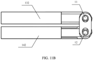
- FIG. 11A is a three-dimensional view when an opening and closing angle is 0° according to Embodiment 1.
- FIG. 11B is a side view when an opening and closing angle is 0° according to Embodiment 1 of this application.
- the first body fastening part 132 is disposed away from the first rotating shaft 11
- the second body fastening part 142 is disposed away from the second rotating shaft 12. Because of interference between the first interference part and the second interference part, the distance between the axis of the first rotating shaft 11 and the axis of the second rotating shaft 12 is the longest.
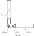
- FIG. 12A is a three-dimensional view when an opening and closing angle is 90° according to Embodiment 1.
- FIG. 12B is a side view when an opening and closing angle is 90° according to Embodiment 1 of this application.
- the first body fastening part 132 is disposed near the first rotating shaft 11, and the second body fastening part 142 is disposed away from the second rotating shaft 12.
- the distance between the axis of the first rotating shaft 11 and the axis of the second rotating shaft 12 is smaller than that in FIG. 11B .
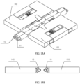
- FIG. 13A is a three-dimensional view when an opening and closing angle is 180° according to Embodiment 1.
- FIG. 13B is a side view when an opening and closing angle is 180° according to Embodiment 1 of this application.
- the first body fastening part 132 is disposed near the first rotating shaft 11
- the second body fastening part 142 is disposed near the second rotating shaft 12.
- no interference is generated between the first interference part and the second interference part
- the distance between the axis of the first rotating shaft 11 and the axis of the second rotating shaft 12 is smaller than that in FIG. 12B
- the distance between the axis of the first rotating shaft 11 and the axis of the second rotating shaft 12 is the smallest.
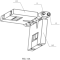
- FIG. 14A is a three-dimensional view when an opening and closing angle is 270° according to Embodiment 1.
- FIG. 14B is a side view when an opening and closing angle is 270° according to Embodiment 1 of this application.
- FIG. 15A is a three-dimensional view when an opening and closing angle is 360° according to Embodiment 1 of this application.
- FIG. 15B is a side view when an opening and closing angle is 360° according to Embodiment 1 of this application.
- the sliding structure is implemented by using components such as the first sliding part and the elastic component, so that the opening and closing mechanism can implement 360° opening and closing in a telescopic manner.
- the opening and closing angle of the opening and closing mechanism is 180°, it can be ensured that there is no gap or a small gap between two screens.
- a rotating shaft torsion force required by the opening and closing mechanism may be provided.
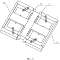
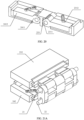
- FIG. 16 is a schematic diagram of an entire mechanism of an opening and closing mechanism according to Example 2, useful for understanding the invention, but not falling in the scope of the claim, of this application.
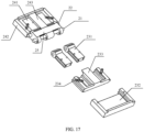
- FIG. 17 is a schematic exploded diagram of an opening and closing mechanism according to Example 2 of this application.
- the first telescopic part 23 includes a first connection part 231 connected to the first rotating shaft 21 and a first body fastening part 232 that may slide along the first connection part 231, and the first body fastening part 232 is configured to fasten a first display screen.
- the second telescopic part 24 includes a second connection part 241 connected to the second rotating shaft 22 and a second body fastening part 242 that may slide along the second connection part 241, and the second body fastening part 242 is configured to fasten a second display screen.
- the first body fastening part 232 slides toward the first rotating shaft 21, and the second body fastening part 242 slides toward the second rotating shaft 22.
- the opening and closing angle is an angle between the first body fastening part 132 and the second body fastening part 142.
- the first body fastening part 232 is an open box structure, and the first connection part 231 is slidingly disposed in the first body fastening part 232.
- the first telescopic part 23 further includes a first sliding part 233 that is slidingly connected to the first connection part 231, and the first sliding part 233 may slide along the first connection part 231, to drive the first body fastening part 232 to slide along the first connection part 231.
- the second telescopic part 24 further includes a second sliding part 243 that is slidingly connected to the second connection part 241, and the second sliding part 243 may slide along the second connection part 241, to drive the second body fastening part 242 to slide along the second connection part 241.
- a structure of the first rotating shaft is the same as a structure of the second rotating shaft
- the structure of the first telescopic part is the same as the structure of the second telescopic part. Therefore, this example is described by using the first rotating shaft and the first telescopic part as an example, and structures of the second rotating shaft and the second telescopic part are not described in detail again.
- the opening and closing mechanism further includes a joint part 25, a part of the first rotating shaft 21 is rotationally disposed in the joint part 25, and a part of the second rotating shaft 22 is rotationally disposed in the joint part 25.
- the joint part 25 includes a first rotating hole 251 and a second rotating hole 252.
- the part of the first rotating shaft 21 is located in the first rotating hole 251, and the part of the second rotating shaft 22 is located in the second rotating hole 252.
- a diameter of the first rotating hole 251 is greater than a diameter of the first rotating shaft 21, and a diameter of the second rotating hole 252 is greater than a diameter of the second rotating shaft 22.
- a first surface of the sharp convex part 2331 and a surface of the joint part 25 are located in a same plane, and a second surface of the sharp convex part 2331 is fitted to the joint part 25.
- the sharp convex part 2331 In a process in which the opening and closing angle is changed from 0° to 180°, because the sharp convex part 2331 is a part protruding from the first sliding part 233, the sharp convex part 2331 interferes with the surface of the joint part 25, so that the first body fastening part 232 is disposed away from the first rotating shaft 21.
- the first telescopic part 23 further includes a chain part 234, and the chain part 234 is configured to connect the first body fastening part 232, the first connection part 231, and the first sliding part 233, and drives the first body fastening part 232 to slide when the first sliding part 233 slides along the first connection part 231.
- a hole is disposed on the chain part 234, and protrusions that can be fastened on the hole are disposed on the first connection part 231, the first sliding part 233, and the first body fastening part 232.
- Three holes are disposed on the chain part 234, a protrusion on the first sliding part 233 is disposed in a middle hole, a protrusion on the first connection part 231 is disposed in an inner side hole, and a protrusion on the first body fastening part 232 is disposed in an outer side hole.
- the first sliding part 233 may slide relative to the first connection part 231, and the first body fastening part 232 may slide relative to the first sliding part 233.
- a first groove is disposed on the first connection part 231, and a sliding cavity accommodating the first sliding part 233 is disposed on the second sliding part 233.
- a first convex part matching the first groove is disposed in the sliding cavity, and the first convex part may slide in the first groove.
- a second convex part is disposed on an outer side of the first sliding part 233, a second groove matching the second convex part is disposed on the first body fastening part 232, and the second groove may slide along the second convex part.
- the sharp convex part 2331 interferes with the surface of the joint part 25, and the first sliding part 233 slides outward relative to the first connection part 231.
- the first sliding part 233 slides outward, because of a function of the chain part 234, the first body fastening part 232 slides outward.
- the interference also occurs between the sharp convex part 2331 and the surface of the joint part 25, but the first sliding part 233 slides inward relative to the first connection part 231.
- the first body fastening part 232 slides inward.
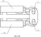
- FIG. 19 is a schematic diagram of an interference structure according to example 2 of this application.
- FIG. 20 is a sectional view of an interference part according to example 2 of this application.
- the first connection part 231 includes a first interference part 2311 sleeved on the first rotating shaft 21 and a first supporting part 2312 connected to the first interference part 2311, and the first body fastening part 232 may slide along the first supporting part 2312.
- the second connection part 241 includes a second interference part 2411 sleeved on the second rotating shaft 22 and a second supporting part 2412 connected to the second interference part 2411, and the second body fastening part 242 may slide along the second supporting part 2412. In a process in which the opening and closing angle is changed from 0° to 180°, the first interference part 2311 and the second interference part 2411 are in an interference state.
- a third interference part 253 is disposed on one side of the joint part 25.
- the opening and closing angle is 180°
- a structure of the third interference part 253 and the first interference part 2311 is shown in FIG. 20 .
- the third interference part 253 is fitted to the first interference part 2311.
- the first interference part 2311 interferes with the third interference part 253, to generate a torsion force, and maintain the opening and closing angle between the first display screen and the second display screen.
- first interference part 1311 and the third interference part 253 exist, a distance between an axis of the first rotating shaft 21 and an axis of the second rotating shaft 22 changes.
- the distance between two axes is a first distance
- the opening and closing angle is 0°
- the distance between the two axes is a second distance.
- the first distance is less than the second distance.
- the diameter of the first rotating hole 251 is greater than the diameter of the first rotating shaft 21, and the diameter of the second rotating hole 252 is greater than the diameter of the second rotating shaft 22, which provides distance space for the foregoing distance change, and ensures generation of an interference process.
- FIG. 21A is a three-dimensional view when an opening and closing angle is 0° according to example 2 of this application.
- FIG. 21B is a side view when an opening and closing angle is 0° according to example 2 of this application.
- the first body fastening part 232 is disposed away from the first rotating shaft 21
- the second body fastening part 242 is disposed away from the second rotating shaft 22. Because of the interference between the first interference part and the third interference part and interference between the second interference part and the third interference part, the distance between the axis of the first rotating shaft 21 and the axis of the second rotating shaft 22 is the longest.
- FIG. 22A is a three-dimensional view when an opening and closing angle is 90° according to example 2 of this application.
- FIG. 22B is a side view when an opening and closing angle is 90° according to example 2 of this application.
- the first body fastening part 232 is disposed near the first rotating shaft 21, and the second body fastening part 242 is disposed away from the second rotating shaft 22.
- the distance between the axis of the first rotating shaft 21 and the axis of the second rotating shaft 22 is smaller than that in FIG. 21B .
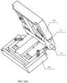
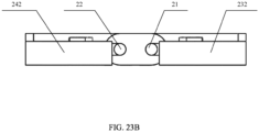
- FIG. 23A is a three-dimensional view when an opening and closing angle is 180° according to example 2 of this application.
- FIG. 23B is a side view when an opening and closing angle is 180° according to example 2 of this application.
- the first body fastening part 232 is disposed near the first rotating shaft 21, and the second body fastening part 242 is disposed near the second rotating shaft 22.
- no interference is generated between the first interference part and the third interference part
- no interference is generated between the second interference part and the third interference part
- the distance between the axis of the first rotating shaft 21 and the axis of the second rotating shaft 22 is smaller than that in FIG. 22B
- the distance between the axis of the first rotating shaft 21 and the axis of the second rotating shaft 22 is the smallest.
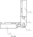
- FIG. 24A is a three-dimensional view when an opening and closing angle is 270° according to example 2 of this application.
- FIG. 24B is a side view when an opening and closing angle is 270° according to example 2 of this application.
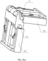
- FIG. 25A is a three-dimensional view when an opening and closing angle is 360° according to example 2 of this application.
- FIG. 25B is a side view when an opening and closing angle is 360° according to example 2 of this application.
- the sliding structure is implemented by using components such as the sharp convex part and the joint part on the first sliding part, so that the opening and closing mechanism can implement 360° opening and closing in a telescopic manner.
- the opening and closing angle of the opening and closing mechanism is 180°, it can be ensured that there is no gap or a small gap between two screens.
- a rotating shaft torsion force required by the opening and closing mechanism may be provided.
- the electronic device includes a first body, a second body, and the opening and closing mechanism that is of a notebook computer and that is described above.
- the first body is connected to the first body fastening part
- the second body is connected to the second body fastening part.
- an example in which the electronic device is a notebook computer the first body is the first display screen
- the second body is the second display screen is used for detailed description.
- the Embodiment 1 and example 2 the following describes a structure of the notebook computer in detail by using Embodiment 3 and example 4.
- the notebook computer in Embodiment 3 uses the opening and closing mechanism in Embodiment 1, and the notebook computer in example 4 uses the opening and closing mechanism in example 2.
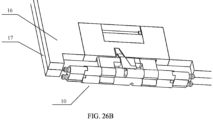
- FIG. 26A is a schematic structural diagram of a notebook computer when an opening and closing angle is 0° according to Embodiment 3 of this invention.
- FIG. 26B is a partial enlarged diagram of FIG. 26A according to an embodiment of this invention. As shown in FIG. 26A and FIG. 26B , when the opening and closing angle is 0°, a first display screen 16 and a second display screen 17 extend outward, and a rotating shaft of an opening and closing mechanism 10 is located outside the first display screen 16 and the second display screen 17.
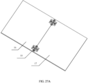
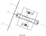
- FIG. 27A is a schematic structural diagram of a notebook computer when an opening and closing angle is 180° according to Embodiment 3 of this invention.
- FIG. 27B is a partial enlarged diagram of FIG. 27A according to an embodiment of this invention. As shown in FIG. 27A and FIG. 27B , the first display screen 16 and the second display screen 17 are aligned, and the opening and closing mechanism 10 is invisible from a screen side (for illustration, the opening and closing mechanism is illustrated in this embodiment).
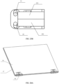
- FIG. 28A is a schematic structural diagram of a notebook computer when an opening and closing angle is 360° according to Embodiment 3 of this invention.
- FIG. 28B is a partial enlarged diagram of FIG. 28A according to an embodiment of this invention. As shown in FIG. 28A and FIG. 28B , the opening and closing mechanism is accommodated in a body, so that the notebook computer can be used as a tablet computer.
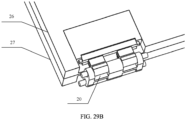
- FIG. 29A is a schematic structural diagram of a notebook computer when an opening and closing angle is 0° according to Example 4, useful for understanding the invention, but not falling in the scope of the claim, of this application.
- FIG. 29B is a partial enlarged diagram of FIG. 29A according to an example of this application. As shown in FIG. 29A and FIG. 29B , when the opening and closing angle is 0°, a first display screen 26 and a second display screen 27 extend outward, and a rotating shaft of an opening and closing mechanism 20 is located outside the first display screen 26 and the second display screen 27.
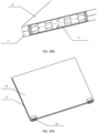
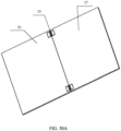
- FIG. 30A is a schematic structural diagram of a notebook computer when an opening and closing angle is 180° according to example 4 of this application.
- FIG. 30B is a partial enlarged diagram of FIG. 30A according to an example of this application. As shown in FIG. 30A and FIG. 30B , the first display screen 26 and the second display screen 27 are aligned, the opening and closing mechanism 20 is invisible from a screen side (for illustration, the opening and closing mechanism is illustrated in this example).
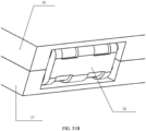
- FIG. 31A is a schematic structural diagram of a notebook computer when an opening and closing angle is 360° according to example 4 of this application.
- FIG. 31B is a partial enlarged diagram of FIG. 31A according to an example of this application.
- the opening and closing mechanism is accommodated in a body, so that the notebook computer can be used as a tablet computer.
- Embodiment 3 and example 4 when the opening and closing angle between the first display screen and the second display screen is 180°, the first display screen and the second display screen are disposed side by side, and there is no gap between the first display screen and the second display screen, so that a full-screen effect can be achieved.
- the opening and closing angle between the first display screen and the second display screen is changed from 180° to 360°, a distance between the first display screen and the first rotating shaft remains unchanged, and a distance between the second display screen and the second rotating shaft remains unchanged.
- the notebook computer is used as a tablet computer.
- the opening and closing angle between the first display screen and the second display screen is changed from 180° to 0°, the first display screen moves away from the first rotating shaft, and the second display screen moves away from the second rotating shaft, to avoid interference of the first rotating shaft and the second rotating shaft on the first display screen and the second display screen, avoid scratching the display screen, and ensure that the notebook computer is opened and closed at 360°.
Landscapes
- Engineering & Computer Science (AREA)
- Computer Hardware Design (AREA)
- Theoretical Computer Science (AREA)
- Physics & Mathematics (AREA)
- Human Computer Interaction (AREA)
- General Engineering & Computer Science (AREA)
- General Physics & Mathematics (AREA)
- Mathematical Physics (AREA)
- Pivots And Pivotal Connections (AREA)
- Casings For Electric Apparatus (AREA)
- Telephone Set Structure (AREA)
Claims (8)
- Öffnungs- und Schließmechanismus, umfassend eine erste Drehwelle (11) und eine zweite Drehwelle (12), die parallel angeordnet sind, ein erstes teleskopisches Teil (13), das auf der ersten Drehwelle (11) angeordnet ist, und ein zweites teleskopisches Teil (14), das auf der zweiten Drehwelle (12) angeordnet ist, wobei die erste Drehwelle (11) und die zweite Drehwelle (12) drehverbunden sind;das erste teleskopische Teil (13) ein erstes Verbindungsteil (131) umfasst, das mit der ersten Drehwelle (11) verbunden ist, und ein erstes Körperbefestigungsteil (132) dazu konfiguriert ist, entlang des ersten Verbindungsteils (131) zu gleiten, wobei das erste Körperbefestigungsteil (132) dazu konfiguriert ist, einen ersten Körper einer elektronischen Vorrichtung zu befestigen,wobei das erste teleskopische Teil (13) ferner ein erstes Gleitteil (133) umfasst, das gleitend mit dem ersten Verbindungsteil (131) verbunden ist, und das erste Gleitteil (133) dazu konfiguriert ist, entlang des ersten Verbindungsteils (131) zu gleiten, um das erste Körperbefestigungsteil (132) dazu anzutreiben, entlang des ersten Verbindungsteils (131) zu gleiten,wobei das erste Verbindungsteil (131) ein erstes Interferenzteil (1311), das auf der ersten Drehwelle (11) umhüllt ist, und ein erstes Stützteil (1312), das mit dem ersten Interferenzteil (1311) verbunden ist, umfasst und das erste Körperbefestigungsteil (132) dazu konfiguriert ist, entlang des ersten Stützteils (1312) zu gleiten,wobei ein Schrägkörper (1333) auf einer Oberfläche des ersten Gleitteils (133) angeordnet ist und eine Gleitöffnung (1321), die zu dem Schrägkörper (1333) passt, auf dem ersten Körperbefestigungsteil (132) angeordnet ist;wobei eine Gleitwelle auf einer Außenumfangsfläche der ersten Drehwelle (11) angeordnet ist, eine Gleitnut (1111) auf der Gleitwelle angeordnet ist und das erste Gleitteil (133) dazu konfiguriert ist, um die Gleitnut (1111) herum zu gleiten, sodass das erste Gleitteil (133) entlang des ersten Verbindungsteils (131) gleitet, um das erste Körperbefestigungsteil (132) dazu anzutreiben, entlang des ersten Verbindungsteils (131) zu gleiten, wobei die Gleitnut (1111) eine schräge Nut (1111A) und eine gerade Nut (1111B), die verbunden sind, umfasst und ein Gleitpunkt (1331) auf einer ersten Seitenfläche des ersten Gleitteils (133) angeordnet ist;das zweite teleskopische Teil (14) ein zweites Verbindungsteil (141), das mit der zweiten Drehwelle (12) verbunden ist, und ein zweites Körperbefestigungsteil (142), das dazu konfiguriert ist, entlang des zweiten Verbindungsteils (141) zu gleiten, umfasst, wobei das zweite Körperbefestigungsteil (142) dazu konfiguriert ist, einen zweiten Körper der elektronischen Vorrichtung zu befestigen; wobei das zweite teleskopische Teil (24) ferner ein zweites Gleitteil (243) umfasst, das gleitend mit dem zweiten Verbindungsteil (241) verbunden ist, und das zweite Gleitteil (243) dazu konfiguriert ist, entlang des zweiten Verbindungsteils (241) zu gleiten, um das zweite Körperbefestigungsteil (142) dazu anzutreiben, entlang des zweiten Verbindungsteils (241) zu gleiten;wobei das zweite Verbindungsteil (241) ein zweites Interferenzteil (1411), das auf der zweiten Drehwelle (12) umhüllt ist, und ein zweites Stützteil (1412), das mit dem zweiten Interferenzteil (1411) verbunden ist, umfasst und das zweite Körperbefestigungsteil (142) dazu konfiguriert ist, entlang des zweiten Stützteils (2412) zu gleiten;wobei, wenn ein Öffnungs- und Schließwinkel von 0° auf 180° verändert wird, das erste Körperbefestigungsteil (132) in Richtung der ersten Drehwelle (11) gleitet und das zweite Körperbefestigungsteil (142) in Richtung der zweiten Drehwelle (12) gleitet, weil der Gleitpunkt (1331) in der schrägen Nut (1111A) gleitet, sodass das erste Gleitteil (133) entlang des ersten Verbindungsteils (131) gleitet, die Gleitöffnung (1321) entlang des Schrägkörpers (1333) gleitet und sich das erste Interferenzteil (1311) und das zweite Interferenzteil (1411) in einem Interferenzzustand befinden; undwobei, wenn der Öffnungs- und Schließwinkel von 180° auf 360° verändert wird, die Gleitöffnung (1312) und der Schrägkörper (1333) relativ stationär sind, ein Abstand zwischen dem ersten Körperbefestigungsteil (132) und der ersten Drehwelle (11) unverändert bleibt, weil der Gleitpunkt (1331) in der geraden Nut gleitet, sodass das erste Gleitteil (133) und das erste Verbindungsteil (131) relativ stationär sind, und ein Abstand zwischen dem zweiten Körperbefestigungsteil (142) und der zweiten Drehwelle (12) unverändert bleibt, wobei der Öffnungs- und Schließwinkel ein Winkel zwischen dem ersten Körperbefestigungsteil (132) und dem zweiten Körperbefestigungsteil (142) ist.
- Mechanismus nach Anspruch 1, wobei eine Nut auf einer zweiten Seitenfläche des ersten Gleitteils (133) angeordnet ist, die Nut dazu konfiguriert ist, entlang des ersten Verbindungsteils (131) zu gleiten, und die zweite Seitenfläche gegenüber der ersten Seitenfläche angeordnet ist.
- Mechanismus nach einem der vorhergehenden Ansprüche, wobei das erste teleskopische Teil ferner eine elastische Komponente und ein positionsbegrenzendes Teil umfasst;das positionsbegrenzende Teil an einem Ende angeordnet ist, das dem ersten Verbindungsteil (131) angehört und das von der ersten Drehwelle (11) weg ist;ein Ende der elastischen Komponente gegen das erste Körperbefestigungsteil (132) drückt und das andere Ende der elastischen Komponente gegen das positionsbegrenzende Teil drückt; unddie elastische Komponente dazu konfiguriert ist, das erste Körperbefestigungsteil (132) aus einer Position, die von der ersten Drehwelle (11) weg ist, in eine Position, die nahe der ersten Drehwelle (11) ist, zurückzuziehen.
- Mechanismus nach Anspruch 3, wobei eine positionsbegrenzende Stufe auf einer Seitenfläche des positionsbegrenzenden Teiles angeordnet ist und, wenn der Öffnungs- und Schließwinkel 0° beträgt, ein Teil des ersten Körperbefestigungsteils (132) gegen die positionsbegrenzende Stufe drückt.
- Mechanismus nach einem der vorhergehenden Ansprüche, wobei das erste Interferenzteil ein C-förmiges Interferenzteil ist; und
wenn der Öffnungs- und Schließwinkel 0° bis 180° beträgt, das erste Interferenzteil mit dem zweiten Interferenzteil interferiert. - Mechanismus nach einem der vorhergehenden Ansprüche, wobei das erste Körperbefestigungsteil (132) eine Gehäusestruktur ist und das erste Körperbefestigungsteil (132) außerhalb des ersten Verbindungsteils (131) umhüllt ist.
- Mechanismus nach einem der Ansprüche 1 bis 6, ferner umfassend ein Gelenkteil, wobei
ein Teil der ersten Drehwelle (11) drehend in dem Gelenkteil angeordnet ist und ein Teil der zweiten Drehwelle (12) drehend in dem Gelenkteil angeordnet ist. - Elektronische Vorrichtung, umfassend einen ersten Körper, einen zweiten Körper und den Öffnungs- und Schließmechanismus nach einem der Ansprüche 1 bis 7, wobeider erste Körper mit dem ersten Körperbefestigungsteil (132) verbunden ist; undder zweite Körper mit dem zweiten Körperbefestigungsteil (142) verbunden ist.
Applications Claiming Priority (1)
| Application Number | Priority Date | Filing Date | Title |
|---|---|---|---|
| PCT/CN2018/083440 WO2019200549A1 (zh) | 2018-04-17 | 2018-04-17 | 开合机构及电子设备 |
Publications (3)
| Publication Number | Publication Date |
|---|---|
| EP3757409A1 EP3757409A1 (de) | 2020-12-30 |
| EP3757409A4 EP3757409A4 (de) | 2021-03-10 |
| EP3757409B1 true EP3757409B1 (de) | 2024-11-27 |
Family
ID=68239308
Family Applications (1)
| Application Number | Title | Priority Date | Filing Date |
|---|---|---|---|
| EP18915360.4A Active EP3757409B1 (de) | 2018-04-17 | 2018-04-17 | Öffnungs- und schliessmechanismus und elektronische vorrichtung |
Country Status (4)
| Country | Link |
|---|---|
| US (1) | US11868186B2 (de) |
| EP (1) | EP3757409B1 (de) |
| CN (1) | CN111556931B (de) |
| WO (1) | WO2019200549A1 (de) |
Families Citing this family (13)
| Publication number | Priority date | Publication date | Assignee | Title |
|---|---|---|---|---|
| CN111095158B (zh) * | 2018-06-20 | 2021-07-16 | 华为技术有限公司 | 一种具有开合性能的设备 |
| EP3809678B1 (de) * | 2018-08-07 | 2023-05-17 | Huawei Technologies Co., Ltd. | Drehwellenverbindungsmechanismus und faltbare vorrichtung |
| CN109992054B (zh) * | 2019-03-30 | 2021-04-13 | 联想(北京)有限公司 | 一种电子设备、连接装置 |
| CN110703857B (zh) * | 2019-09-26 | 2021-04-13 | 联想(北京)有限公司 | 转轴和电子设备 |
| TWI739561B (zh) * | 2019-12-23 | 2021-09-11 | 仁寶電腦工業股份有限公司 | 電子裝置 |
| CN113498284B (zh) * | 2020-04-08 | 2023-03-14 | 富世达股份有限公司 | 双屏转轴结构 |
| TWI751764B (zh) * | 2020-10-30 | 2022-01-01 | 宏碁股份有限公司 | 轉軸機構 |
| EP4250693B1 (de) * | 2021-02-18 | 2026-01-14 | Samsung Electronics Co., Ltd. | Elektronische vorrichtung mit scharniermodul |
| KR102814980B1 (ko) * | 2021-02-18 | 2025-05-30 | 삼성전자 주식회사 | 힌지 모듈을 포함하는 전자 장치 |
| CN114356035B (zh) * | 2022-01-19 | 2024-07-02 | 合肥联宝信息技术有限公司 | 一种双向开合机构及电子设备 |
| CN119301937A (zh) * | 2022-06-10 | 2025-01-10 | 三星电子株式会社 | 包括铰链装置的电子装置 |
| CN218882773U (zh) * | 2022-07-21 | 2023-04-18 | 华为技术有限公司 | 转轴组件和电子设备 |
| CN118728836A (zh) * | 2023-03-31 | 2024-10-01 | 华为技术有限公司 | 一种转轴机构及电子设备 |
Family Cites Families (14)
| Publication number | Priority date | Publication date | Assignee | Title |
|---|---|---|---|---|
| CN101388918B (zh) * | 2007-09-14 | 2013-10-09 | 京瓷株式会社 | 电子设备 |
| KR20100107999A (ko) * | 2009-03-27 | 2010-10-06 | 이태진 | 이동통신기기용 슬라이드 힌지모듈 |
| CN102635627B (zh) * | 2011-11-28 | 2014-09-03 | 联想(北京)有限公司 | 铰链装置及便携终端 |
| KR102034585B1 (ko) * | 2013-07-09 | 2019-10-21 | 엘지전자 주식회사 | 디스플레이 장치 |
| US9500013B2 (en) | 2013-07-25 | 2016-11-22 | Hewlett-Packard Development Company, L.P. | Hinge assembly for a computing device |
| CN105202010A (zh) * | 2014-06-12 | 2015-12-30 | 加藤电机(香港)有限公司 | 双轴铰链及应用此双轴铰链的终端机器 |
| JP6544734B2 (ja) * | 2015-01-14 | 2019-07-17 | 株式会社ナチュラレーザ・ワン | 2軸ヒンジ及びこの2軸ヒンジを用いた電子機器 |
| CN205895879U (zh) * | 2016-01-27 | 2017-01-18 | 杭州安费诺飞凤通信部品有限公司 | 一种铰链机构及移动终端 |
| US10364598B2 (en) * | 2016-09-02 | 2019-07-30 | Microsoft Technology Licensing, Llc | Hinged device |
| CN206723246U (zh) * | 2017-03-20 | 2017-12-08 | 杭州安费诺飞凤通信部品有限公司 | 移动终端的新型铰链机构及移动终端 |
| CN207200775U (zh) * | 2017-04-06 | 2018-04-06 | 杭州安费诺飞凤通信部品有限公司 | 柔性屏移动终端的铰链、铰链装置及柔性屏移动终端 |
| CN206918043U (zh) | 2017-04-19 | 2018-01-23 | 广东欧珀移动通信有限公司 | 转轴组件及可折叠终端 |
| CN207117712U (zh) * | 2017-09-06 | 2018-03-16 | 广东欧珀移动通信有限公司 | 可折叠移动终端 |
| CN107654484A (zh) * | 2017-09-26 | 2018-02-02 | 联想(北京)有限公司 | 一种连接部件及柔性显示屏、柔性电子设备 |
-
2018
- 2018-04-17 EP EP18915360.4A patent/EP3757409B1/de active Active
- 2018-04-17 US US15/733,633 patent/US11868186B2/en active Active
- 2018-04-17 CN CN201880085227.7A patent/CN111556931B/zh active Active
- 2018-04-17 WO PCT/CN2018/083440 patent/WO2019200549A1/zh not_active Ceased
Also Published As
| Publication number | Publication date |
|---|---|
| US20210018960A1 (en) | 2021-01-21 |
| EP3757409A1 (de) | 2020-12-30 |
| CN111556931B (zh) | 2021-10-15 |
| WO2019200549A1 (zh) | 2019-10-24 |
| CN111556931A (zh) | 2020-08-18 |
| US11868186B2 (en) | 2024-01-09 |
| EP3757409A4 (de) | 2021-03-10 |
Similar Documents
| Publication | Publication Date | Title |
|---|---|---|
| EP3757409B1 (de) | Öffnungs- und schliessmechanismus und elektronische vorrichtung | |
| US12399534B2 (en) | Folding mechanism and electronic device | |
| CN112527049B (zh) | 折叠式电子装置 | |
| US9500013B2 (en) | Hinge assembly for a computing device | |
| TWI656433B (zh) | 轉軸模組與應用其的電子裝置 | |
| CN102597904B (zh) | 显示区域可变型显示装置 | |
| US10656685B2 (en) | Hinge module and electronic device using the same | |
| US8978209B1 (en) | Hinge structure | |
| KR102353779B1 (ko) | 폴딩부 길이조절이 가능한 폴더블 휴대폰용 케이스 | |
| CN107370848B (zh) | 可折叠移动终端及其折叠机构和折叠组件 | |
| US9122454B2 (en) | Hinge module and electronic device | |
| EP3985268B1 (de) | Doppeldrehwellenmechanismus, faltanordnung und elektronisches gerät | |
| US20250097330A1 (en) | Folding mechanism and electronic device | |
| US10146269B2 (en) | Computing device with a rotatable display member | |
| CN113534893B (zh) | 折叠式电子装置 | |
| US12535864B2 (en) | Electronic device | |
| WO2020177708A1 (zh) | 链节、铰链以及移动终端 | |
| KR20190067401A (ko) | 폴더블 디스플레이 장치의 듀얼힌지장치 | |
| US20180188781A1 (en) | Linking mechanism for a computing device with a rotatable display member | |
| CN115398374B (zh) | 升降式双轴铰链及应用此升降式双轴铰链的终端机器 | |
| JPWO2021210075A5 (de) | ||
| KR102527980B1 (ko) | 양방향 폴딩 힌지장치 | |
| JP4576568B2 (ja) | ヒンジ構造、及び折り畳み式電子機器 | |
| TWM539065U (zh) | 電子裝置 | |
| CN100507803C (zh) | 转轴制约装置 |
Legal Events
| Date | Code | Title | Description |
|---|---|---|---|
| STAA | Information on the status of an ep patent application or granted ep patent |
Free format text: STATUS: THE INTERNATIONAL PUBLICATION HAS BEEN MADE |
|
| PUAI | Public reference made under article 153(3) epc to a published international application that has entered the european phase |
Free format text: ORIGINAL CODE: 0009012 |
|
| STAA | Information on the status of an ep patent application or granted ep patent |
Free format text: STATUS: REQUEST FOR EXAMINATION WAS MADE |
|
| 17P | Request for examination filed |
Effective date: 20200923 |
|
| AK | Designated contracting states |
Kind code of ref document: A1 Designated state(s): AL AT BE BG CH CY CZ DE DK EE ES FI FR GB GR HR HU IE IS IT LI LT LU LV MC MK MT NL NO PL PT RO RS SE SI SK SM TR |
|
| AX | Request for extension of the european patent |
Extension state: BA ME |
|
| A4 | Supplementary search report drawn up and despatched |
Effective date: 20210204 |
|
| RIC1 | Information provided on ipc code assigned before grant |
Ipc: F16C 11/04 20060101AFI20210129BHEP Ipc: G06F 1/16 20060101ALI20210129BHEP |
|
| DAV | Request for validation of the european patent (deleted) | ||
| DAX | Request for extension of the european patent (deleted) | ||
| STAA | Information on the status of an ep patent application or granted ep patent |
Free format text: STATUS: EXAMINATION IS IN PROGRESS |
|
| 17Q | First examination report despatched |
Effective date: 20220608 |
|
| GRAP | Despatch of communication of intention to grant a patent |
Free format text: ORIGINAL CODE: EPIDOSNIGR1 |
|
| STAA | Information on the status of an ep patent application or granted ep patent |
Free format text: STATUS: GRANT OF PATENT IS INTENDED |
|
| INTG | Intention to grant announced |
Effective date: 20240705 |
|
| GRAS | Grant fee paid |
Free format text: ORIGINAL CODE: EPIDOSNIGR3 |
|
| GRAA | (expected) grant |
Free format text: ORIGINAL CODE: 0009210 |
|
| STAA | Information on the status of an ep patent application or granted ep patent |
Free format text: STATUS: THE PATENT HAS BEEN GRANTED |
|
| AK | Designated contracting states |
Kind code of ref document: B1 Designated state(s): AL AT BE BG CH CY CZ DE DK EE ES FI FR GB GR HR HU IE IS IT LI LT LU LV MC MK MT NL NO PL PT RO RS SE SI SK SM TR |
|
| REG | Reference to a national code |
Ref country code: GB Ref legal event code: FG4D |
|
| REG | Reference to a national code |
Ref country code: CH Ref legal event code: EP |
|
| REG | Reference to a national code |
Ref country code: IE Ref legal event code: FG4D |
|
| REG | Reference to a national code |
Ref country code: DE Ref legal event code: R096 Ref document number: 602018077120 Country of ref document: DE |
|
| REG | Reference to a national code |
Ref country code: LT Ref legal event code: MG9D |
|
| REG | Reference to a national code |
Ref country code: NL Ref legal event code: MP Effective date: 20241127 |
|
| PG25 | Lapsed in a contracting state [announced via postgrant information from national office to epo] |
Ref country code: IS Free format text: LAPSE BECAUSE OF FAILURE TO SUBMIT A TRANSLATION OF THE DESCRIPTION OR TO PAY THE FEE WITHIN THE PRESCRIBED TIME-LIMIT Effective date: 20250327 Ref country code: HR Free format text: LAPSE BECAUSE OF FAILURE TO SUBMIT A TRANSLATION OF THE DESCRIPTION OR TO PAY THE FEE WITHIN THE PRESCRIBED TIME-LIMIT Effective date: 20241127 Ref country code: PT Free format text: LAPSE BECAUSE OF FAILURE TO SUBMIT A TRANSLATION OF THE DESCRIPTION OR TO PAY THE FEE WITHIN THE PRESCRIBED TIME-LIMIT Effective date: 20250327 |
|
| PG25 | Lapsed in a contracting state [announced via postgrant information from national office to epo] |
Ref country code: NL Free format text: LAPSE BECAUSE OF FAILURE TO SUBMIT A TRANSLATION OF THE DESCRIPTION OR TO PAY THE FEE WITHIN THE PRESCRIBED TIME-LIMIT Effective date: 20241127 Ref country code: FI Free format text: LAPSE BECAUSE OF FAILURE TO SUBMIT A TRANSLATION OF THE DESCRIPTION OR TO PAY THE FEE WITHIN THE PRESCRIBED TIME-LIMIT Effective date: 20241127 |
|
| REG | Reference to a national code |
Ref country code: AT Ref legal event code: MK05 Ref document number: 1745972 Country of ref document: AT Kind code of ref document: T Effective date: 20241127 |
|
| PG25 | Lapsed in a contracting state [announced via postgrant information from national office to epo] |
Ref country code: BG Free format text: LAPSE BECAUSE OF FAILURE TO SUBMIT A TRANSLATION OF THE DESCRIPTION OR TO PAY THE FEE WITHIN THE PRESCRIBED TIME-LIMIT Effective date: 20241127 |
|
| PG25 | Lapsed in a contracting state [announced via postgrant information from national office to epo] |
Ref country code: ES Free format text: LAPSE BECAUSE OF FAILURE TO SUBMIT A TRANSLATION OF THE DESCRIPTION OR TO PAY THE FEE WITHIN THE PRESCRIBED TIME-LIMIT Effective date: 20241127 |
|
| PG25 | Lapsed in a contracting state [announced via postgrant information from national office to epo] |
Ref country code: NO Free format text: LAPSE BECAUSE OF FAILURE TO SUBMIT A TRANSLATION OF THE DESCRIPTION OR TO PAY THE FEE WITHIN THE PRESCRIBED TIME-LIMIT Effective date: 20250227 |
|
| PG25 | Lapsed in a contracting state [announced via postgrant information from national office to epo] |
Ref country code: LV Free format text: LAPSE BECAUSE OF FAILURE TO SUBMIT A TRANSLATION OF THE DESCRIPTION OR TO PAY THE FEE WITHIN THE PRESCRIBED TIME-LIMIT Effective date: 20241127 Ref country code: AT Free format text: LAPSE BECAUSE OF FAILURE TO SUBMIT A TRANSLATION OF THE DESCRIPTION OR TO PAY THE FEE WITHIN THE PRESCRIBED TIME-LIMIT Effective date: 20241127 Ref country code: GR Free format text: LAPSE BECAUSE OF FAILURE TO SUBMIT A TRANSLATION OF THE DESCRIPTION OR TO PAY THE FEE WITHIN THE PRESCRIBED TIME-LIMIT Effective date: 20250228 |
|
| PG25 | Lapsed in a contracting state [announced via postgrant information from national office to epo] |
Ref country code: PL Free format text: LAPSE BECAUSE OF FAILURE TO SUBMIT A TRANSLATION OF THE DESCRIPTION OR TO PAY THE FEE WITHIN THE PRESCRIBED TIME-LIMIT Effective date: 20241127 |
|
| PGFP | Annual fee paid to national office [announced via postgrant information from national office to epo] |
Ref country code: GB Payment date: 20250306 Year of fee payment: 8 |
|
| PG25 | Lapsed in a contracting state [announced via postgrant information from national office to epo] |
Ref country code: RS Free format text: LAPSE BECAUSE OF FAILURE TO SUBMIT A TRANSLATION OF THE DESCRIPTION OR TO PAY THE FEE WITHIN THE PRESCRIBED TIME-LIMIT Effective date: 20250227 |
|
| PG25 | Lapsed in a contracting state [announced via postgrant information from national office to epo] |
Ref country code: SM Free format text: LAPSE BECAUSE OF FAILURE TO SUBMIT A TRANSLATION OF THE DESCRIPTION OR TO PAY THE FEE WITHIN THE PRESCRIBED TIME-LIMIT Effective date: 20241127 |
|
| PGFP | Annual fee paid to national office [announced via postgrant information from national office to epo] |
Ref country code: DE Payment date: 20250305 Year of fee payment: 8 |
|
| PG25 | Lapsed in a contracting state [announced via postgrant information from national office to epo] |
Ref country code: DK Free format text: LAPSE BECAUSE OF FAILURE TO SUBMIT A TRANSLATION OF THE DESCRIPTION OR TO PAY THE FEE WITHIN THE PRESCRIBED TIME-LIMIT Effective date: 20241127 |
|
| PG25 | Lapsed in a contracting state [announced via postgrant information from national office to epo] |
Ref country code: EE Free format text: LAPSE BECAUSE OF FAILURE TO SUBMIT A TRANSLATION OF THE DESCRIPTION OR TO PAY THE FEE WITHIN THE PRESCRIBED TIME-LIMIT Effective date: 20241127 |
|
| PG25 | Lapsed in a contracting state [announced via postgrant information from national office to epo] |
Ref country code: RO Free format text: LAPSE BECAUSE OF FAILURE TO SUBMIT A TRANSLATION OF THE DESCRIPTION OR TO PAY THE FEE WITHIN THE PRESCRIBED TIME-LIMIT Effective date: 20241127 |
|
| PG25 | Lapsed in a contracting state [announced via postgrant information from national office to epo] |
Ref country code: SK Free format text: LAPSE BECAUSE OF FAILURE TO SUBMIT A TRANSLATION OF THE DESCRIPTION OR TO PAY THE FEE WITHIN THE PRESCRIBED TIME-LIMIT Effective date: 20241127 |
|
| PG25 | Lapsed in a contracting state [announced via postgrant information from national office to epo] |
Ref country code: CZ Free format text: LAPSE BECAUSE OF FAILURE TO SUBMIT A TRANSLATION OF THE DESCRIPTION OR TO PAY THE FEE WITHIN THE PRESCRIBED TIME-LIMIT Effective date: 20241127 |
|
| PG25 | Lapsed in a contracting state [announced via postgrant information from national office to epo] |
Ref country code: IT Free format text: LAPSE BECAUSE OF FAILURE TO SUBMIT A TRANSLATION OF THE DESCRIPTION OR TO PAY THE FEE WITHIN THE PRESCRIBED TIME-LIMIT Effective date: 20241127 |
|
| REG | Reference to a national code |
Ref country code: DE Ref legal event code: R097 Ref document number: 602018077120 Country of ref document: DE |
|
| PG25 | Lapsed in a contracting state [announced via postgrant information from national office to epo] |
Ref country code: SE Free format text: LAPSE BECAUSE OF FAILURE TO SUBMIT A TRANSLATION OF THE DESCRIPTION OR TO PAY THE FEE WITHIN THE PRESCRIBED TIME-LIMIT Effective date: 20241127 |
|
| PLBE | No opposition filed within time limit |
Free format text: ORIGINAL CODE: 0009261 |
|
| STAA | Information on the status of an ep patent application or granted ep patent |
Free format text: STATUS: NO OPPOSITION FILED WITHIN TIME LIMIT |
|
| REG | Reference to a national code |
Ref country code: CH Ref legal event code: L10 Free format text: ST27 STATUS EVENT CODE: U-0-0-L10-L00 (AS PROVIDED BY THE NATIONAL OFFICE) Effective date: 20251008 |
|
| 26N | No opposition filed |
Effective date: 20250828 |
|
| REG | Reference to a national code |
Ref country code: CH Ref legal event code: H13 Free format text: ST27 STATUS EVENT CODE: U-0-0-H10-H13 (AS PROVIDED BY THE NATIONAL OFFICE) Effective date: 20251125 |
|
| PG25 | Lapsed in a contracting state [announced via postgrant information from national office to epo] |
Ref country code: LU Free format text: LAPSE BECAUSE OF NON-PAYMENT OF DUE FEES Effective date: 20250417 |
|
| PG25 | Lapsed in a contracting state [announced via postgrant information from national office to epo] |
Ref country code: MC Free format text: LAPSE BECAUSE OF FAILURE TO SUBMIT A TRANSLATION OF THE DESCRIPTION OR TO PAY THE FEE WITHIN THE PRESCRIBED TIME-LIMIT Effective date: 20241127 |
|
| REG | Reference to a national code |
Ref country code: BE Ref legal event code: MM Effective date: 20250430 |
|
| PG25 | Lapsed in a contracting state [announced via postgrant information from national office to epo] |
Ref country code: FR Free format text: LAPSE BECAUSE OF NON-PAYMENT OF DUE FEES Effective date: 20250430 |
|
| PG25 | Lapsed in a contracting state [announced via postgrant information from national office to epo] |
Ref country code: BE Free format text: LAPSE BECAUSE OF NON-PAYMENT OF DUE FEES Effective date: 20250430 |
|
| PG25 | Lapsed in a contracting state [announced via postgrant information from national office to epo] |
Ref country code: CH Free format text: LAPSE BECAUSE OF NON-PAYMENT OF DUE FEES Effective date: 20250430 |