EP3757373A1 - Straddled vehicle - Google Patents
Straddled vehicle Download PDFInfo
- Publication number
- EP3757373A1 EP3757373A1 EP20182576.7A EP20182576A EP3757373A1 EP 3757373 A1 EP3757373 A1 EP 3757373A1 EP 20182576 A EP20182576 A EP 20182576A EP 3757373 A1 EP3757373 A1 EP 3757373A1
- Authority
- EP
- European Patent Office
- Prior art keywords
- torque
- mode
- internal combustion
- engine
- combustion engine
- Prior art date
- Legal status (The legal status is an assumption and is not a legal conclusion. Google has not performed a legal analysis and makes no representation as to the accuracy of the status listed.)
- Granted
Links
- 239000000446 fuel Substances 0.000 claims abstract description 101
- 238000002485 combustion reaction Methods 0.000 claims abstract description 96
- 239000000654 additive Substances 0.000 claims abstract description 93
- 230000000996 additive effect Effects 0.000 claims abstract description 93
- 238000002347 injection Methods 0.000 claims description 24
- 239000007924 injection Substances 0.000 claims description 24
- 230000005540 biological transmission Effects 0.000 claims description 14
- 238000000034 method Methods 0.000 claims description 12
- 230000008859 change Effects 0.000 claims description 11
- 230000007423 decrease Effects 0.000 claims description 4
- 238000010586 diagram Methods 0.000 description 16
- 230000001133 acceleration Effects 0.000 description 10
- 230000002238 attenuated effect Effects 0.000 description 4
- 238000001514 detection method Methods 0.000 description 3
- 230000008569 process Effects 0.000 description 3
- 230000004044 response Effects 0.000 description 3
- 239000002826 coolant Substances 0.000 description 2
- 230000000881 depressing effect Effects 0.000 description 2
- 230000000994 depressogenic effect Effects 0.000 description 2
- 230000009467 reduction Effects 0.000 description 2
- 230000001419 dependent effect Effects 0.000 description 1
- 230000000694 effects Effects 0.000 description 1
- 239000002828 fuel tank Substances 0.000 description 1
Images


Classifications
-
- B—PERFORMING OPERATIONS; TRANSPORTING
- B62—LAND VEHICLES FOR TRAVELLING OTHERWISE THAN ON RAILS
- B62L—BRAKES SPECIALLY ADAPTED FOR CYCLES
- B62L3/00—Brake-actuating mechanisms; Arrangements thereof
-
- F—MECHANICAL ENGINEERING; LIGHTING; HEATING; WEAPONS; BLASTING
- F02—COMBUSTION ENGINES; HOT-GAS OR COMBUSTION-PRODUCT ENGINE PLANTS
- F02D—CONTROLLING COMBUSTION ENGINES
- F02D11/00—Arrangements for, or adaptations to, non-automatic engine control initiation means, e.g. operator initiated
- F02D11/06—Arrangements for, or adaptations to, non-automatic engine control initiation means, e.g. operator initiated characterised by non-mechanical control linkages, e.g. fluid control linkages or by control linkages with power drive or assistance
- F02D11/10—Arrangements for, or adaptations to, non-automatic engine control initiation means, e.g. operator initiated characterised by non-mechanical control linkages, e.g. fluid control linkages or by control linkages with power drive or assistance of the electric type
- F02D11/105—Arrangements for, or adaptations to, non-automatic engine control initiation means, e.g. operator initiated characterised by non-mechanical control linkages, e.g. fluid control linkages or by control linkages with power drive or assistance of the electric type characterised by the function converting demand to actuation, e.g. a map indicating relations between an accelerator pedal position and throttle valve opening or target engine torque
-
- B—PERFORMING OPERATIONS; TRANSPORTING
- B60—VEHICLES IN GENERAL
- B60T—VEHICLE BRAKE CONTROL SYSTEMS OR PARTS THEREOF; BRAKE CONTROL SYSTEMS OR PARTS THEREOF, IN GENERAL; ARRANGEMENT OF BRAKING ELEMENTS ON VEHICLES IN GENERAL; PORTABLE DEVICES FOR PREVENTING UNWANTED MOVEMENT OF VEHICLES; VEHICLE MODIFICATIONS TO FACILITATE COOLING OF BRAKES
- B60T7/00—Brake-action initiating means
- B60T7/12—Brake-action initiating means for automatic initiation; for initiation not subject to will of driver or passenger
-
- B—PERFORMING OPERATIONS; TRANSPORTING
- B60—VEHICLES IN GENERAL
- B60T—VEHICLE BRAKE CONTROL SYSTEMS OR PARTS THEREOF; BRAKE CONTROL SYSTEMS OR PARTS THEREOF, IN GENERAL; ARRANGEMENT OF BRAKING ELEMENTS ON VEHICLES IN GENERAL; PORTABLE DEVICES FOR PREVENTING UNWANTED MOVEMENT OF VEHICLES; VEHICLE MODIFICATIONS TO FACILITATE COOLING OF BRAKES
- B60T8/00—Arrangements for adjusting wheel-braking force to meet varying vehicular or ground-surface conditions, e.g. limiting or varying distribution of braking force
- B60T8/17—Using electrical or electronic regulation means to control braking
- B60T8/1701—Braking or traction control means specially adapted for particular types of vehicles
- B60T8/1706—Braking or traction control means specially adapted for particular types of vehicles for single-track vehicles, e.g. motorcycles
-
- F—MECHANICAL ENGINEERING; LIGHTING; HEATING; WEAPONS; BLASTING
- F02—COMBUSTION ENGINES; HOT-GAS OR COMBUSTION-PRODUCT ENGINE PLANTS
- F02D—CONTROLLING COMBUSTION ENGINES
- F02D41/00—Electrical control of supply of combustible mixture or its constituents
- F02D41/0002—Controlling intake air
- F02D41/0005—Controlling intake air during deceleration
-
- F—MECHANICAL ENGINEERING; LIGHTING; HEATING; WEAPONS; BLASTING
- F02—COMBUSTION ENGINES; HOT-GAS OR COMBUSTION-PRODUCT ENGINE PLANTS
- F02D—CONTROLLING COMBUSTION ENGINES
- F02D41/00—Electrical control of supply of combustible mixture or its constituents
- F02D41/02—Circuit arrangements for generating control signals
- F02D41/04—Introducing corrections for particular operating conditions
- F02D41/045—Detection of accelerating or decelerating state
-
- B—PERFORMING OPERATIONS; TRANSPORTING
- B60—VEHICLES IN GENERAL
- B60T—VEHICLE BRAKE CONTROL SYSTEMS OR PARTS THEREOF; BRAKE CONTROL SYSTEMS OR PARTS THEREOF, IN GENERAL; ARRANGEMENT OF BRAKING ELEMENTS ON VEHICLES IN GENERAL; PORTABLE DEVICES FOR PREVENTING UNWANTED MOVEMENT OF VEHICLES; VEHICLE MODIFICATIONS TO FACILITATE COOLING OF BRAKES
- B60T2201/00—Particular use of vehicle brake systems; Special systems using also the brakes; Special software modules within the brake system controller
- B60T2201/06—Hill holder; Start aid systems on inclined road
-
- F—MECHANICAL ENGINEERING; LIGHTING; HEATING; WEAPONS; BLASTING
- F02—COMBUSTION ENGINES; HOT-GAS OR COMBUSTION-PRODUCT ENGINE PLANTS
- F02B—INTERNAL-COMBUSTION PISTON ENGINES; COMBUSTION ENGINES IN GENERAL
- F02B61/00—Adaptations of engines for driving vehicles or for driving propellers; Combinations of engines with gearing
- F02B61/02—Adaptations of engines for driving vehicles or for driving propellers; Combinations of engines with gearing for driving cycles
-
- F—MECHANICAL ENGINEERING; LIGHTING; HEATING; WEAPONS; BLASTING
- F02—COMBUSTION ENGINES; HOT-GAS OR COMBUSTION-PRODUCT ENGINE PLANTS
- F02D—CONTROLLING COMBUSTION ENGINES
- F02D2200/00—Input parameters for engine control
- F02D2200/02—Input parameters for engine control the parameters being related to the engine
- F02D2200/10—Parameters related to the engine output, e.g. engine torque or engine speed
- F02D2200/1002—Output torque
-
- F—MECHANICAL ENGINEERING; LIGHTING; HEATING; WEAPONS; BLASTING
- F02—COMBUSTION ENGINES; HOT-GAS OR COMBUSTION-PRODUCT ENGINE PLANTS
- F02D—CONTROLLING COMBUSTION ENGINES
- F02D2200/00—Input parameters for engine control
- F02D2200/02—Input parameters for engine control the parameters being related to the engine
- F02D2200/10—Parameters related to the engine output, e.g. engine torque or engine speed
- F02D2200/101—Engine speed
-
- F—MECHANICAL ENGINEERING; LIGHTING; HEATING; WEAPONS; BLASTING
- F02—COMBUSTION ENGINES; HOT-GAS OR COMBUSTION-PRODUCT ENGINE PLANTS
- F02D—CONTROLLING COMBUSTION ENGINES
- F02D2200/00—Input parameters for engine control
- F02D2200/60—Input parameters for engine control said parameters being related to the driver demands or status
- F02D2200/602—Pedal position
-
- F—MECHANICAL ENGINEERING; LIGHTING; HEATING; WEAPONS; BLASTING
- F02—COMBUSTION ENGINES; HOT-GAS OR COMBUSTION-PRODUCT ENGINE PLANTS
- F02D—CONTROLLING COMBUSTION ENGINES
- F02D2200/00—Input parameters for engine control
- F02D2200/60—Input parameters for engine control said parameters being related to the driver demands or status
- F02D2200/604—Engine control mode selected by driver, e.g. to manually start particle filter regeneration or to select driving style
-
- F—MECHANICAL ENGINEERING; LIGHTING; HEATING; WEAPONS; BLASTING
- F02—COMBUSTION ENGINES; HOT-GAS OR COMBUSTION-PRODUCT ENGINE PLANTS
- F02D—CONTROLLING COMBUSTION ENGINES
- F02D41/00—Electrical control of supply of combustible mixture or its constituents
- F02D41/02—Circuit arrangements for generating control signals
- F02D41/021—Introducing corrections for particular conditions exterior to the engine
- F02D41/0215—Introducing corrections for particular conditions exterior to the engine in relation with elements of the transmission
- F02D41/0225—Introducing corrections for particular conditions exterior to the engine in relation with elements of the transmission in relation with the gear ratio or shift lever position
-
- F—MECHANICAL ENGINEERING; LIGHTING; HEATING; WEAPONS; BLASTING
- F02—COMBUSTION ENGINES; HOT-GAS OR COMBUSTION-PRODUCT ENGINE PLANTS
- F02D—CONTROLLING COMBUSTION ENGINES
- F02D41/00—Electrical control of supply of combustible mixture or its constituents
- F02D41/02—Circuit arrangements for generating control signals
- F02D41/04—Introducing corrections for particular operating conditions
- F02D41/12—Introducing corrections for particular operating conditions for deceleration
- F02D41/123—Introducing corrections for particular operating conditions for deceleration the fuel injection being cut-off
-
- F—MECHANICAL ENGINEERING; LIGHTING; HEATING; WEAPONS; BLASTING
- F02—COMBUSTION ENGINES; HOT-GAS OR COMBUSTION-PRODUCT ENGINE PLANTS
- F02D—CONTROLLING COMBUSTION ENGINES
- F02D41/00—Electrical control of supply of combustible mixture or its constituents
- F02D41/24—Electrical control of supply of combustible mixture or its constituents characterised by the use of digital means
- F02D41/2406—Electrical control of supply of combustible mixture or its constituents characterised by the use of digital means using essentially read only memories
- F02D41/2409—Addressing techniques specially adapted therefor
- F02D41/2422—Selective use of one or more tables
Definitions
- the present invention relates to a straddled vehicle and to a method for controlling a straddled vehicle.
- JP 2016-17517 A discloses such a vehicle.
- the vehicle includes an accelerator sensor that detects the amount of depression of the accelerator pedal, and a controller device that controls the engine based on the accelerator opening signal output from the accelerator sensor.
- an amplified accelerator opening signal is output in response to a normal amount of depression of the accelerator pedal.
- an attenuated accelerator opening signal is output in response to a normal amount of depression of the accelerator pedal.
- a sharp acceleration is obtained for a small amount of depression of the accelerator pedal.
- a mild acceleration is obtained for a large amount of depression of the accelerator pedal.
- the vehicle is also capable of an engine brake control for controlling the degree of engine braking while decelerating.
- the vehicle is configured so that it is possible to turn ON/OFF the engine brake control.
- the engine brake control is provided for the purpose of eliminating awkwardness, which is felt upon actuation of engine brake when the passenger inadvertently releases the accelerator while the vehicle is running.
- the accelerator sensor When it is detected that the passenger was depressing the accelerator pedal and is no longer depressing the accelerator pedal, the accelerator sensor outputs a pseudo-accelerator opening signal.
- the controller device controls the degree of engine braking so that engine brake is not actuated until the accelerator pedal is depressed again or the brake pedal is depressed. This eliminates awkwardness, allowing the passenger to enjoy a smooth driveability.
- the vehicle disclosed in JP 2016-17517 A is an automobile having an accelerator pedal.
- a straddled vehicle has a small weight than an automobile.
- the driveability varies significantly depending on the degree of engine braking not only when the amount of operation of the accelerator (hereinafter referred to as the accelerator operation amount) is zero but also when it is greater than zero. That is, with a straddled vehicle, as compared with an automobile, the driveability is influenced more significantly by the degree of engine braking. Therefore, one may consider controlling the degree of engine braking also when the accelerator operation amount is greater than zero.
- the throttle opening S may be controlled to be a constant value Sc when engine brake is actuated (i.e., when decelerating), as shown in FIG. 13 , for example. Then, the throttle opening S is prevented from becoming less than Sc while an engine brake control is on. Note that the horizontal axis of FIG. 13 represents the accelerator operation amount A, and the vertical axis thereof represents the throttle opening S. With such a control, however, when the passenger increases the accelerator operation amount A from zero, the throttle opening S does not increase until the accelerator operation amount A reaches a predetermined value Ac. Even if the accelerator is operated, the engine torque does not increase for a while. Therefore, the accelerator operation by the passenger does not feel matching with the behavior of the engine torque, failing to realize a desirable driveability.
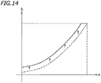
- the throttle opening S may be controlled to be increased uniformly by a certain amount, irrespective of the accelerator operation amount A.
- the throttle opening S for the accelerator operation amount A changes similarly in a region where the accelerator operation amount A is large as well as in a region where the accelerator operation amount A is small.
- the throttle opening S for the accelerator operation amount A is pre-configured so as to realize a desirable driveability. The driveability deteriorates if the throttle opening S changes in a region where the accelerator operation amount A is large.
- said object is solved by a straddled vehicle having the features of independent claim 1.
- said object is solved by method for controlling a straddled vehicle having the features of independent claim 13. Preferred embodiments are laid down in the dependent claims.
- a straddled vehicle disclosed herein includes: an internal combustion engine including an electronic throttle valve provided in an intake passage and a fuel injector that injects fuel; an accelerator that is operated by a passenger; an accelerator sensor that detects an amount of operation of the accelerator; an engine torque sensor that detects a torque of the internal combustion engine; an engine controller device that controls the torque of the internal combustion engine; an engine brake controller device that controls a degree of engine braking, which is actuated by the torque of the internal combustion engine becoming less than zero; and a mode setter that selectively sets one of at least a normal mode in which the degree of engine braking is not reduced and a first reduced mode in which the degree of engine braking is reduced.
- the engine controller device includes a calculator that calculates a target torque based at least on the amount of operation of the accelerator, and a controller that controls the electronic throttle valve and the fuel injector so that the torque of the internal combustion engine is equal to the target torque.
- the engine brake controller device includes a target torque corrector that corrects the target torque by adding a first additive torque to the target torque, which is calculated by the calculator when the torque of the internal combustion engine is less than zero while in the first reduced mode.
- the first additive torque is set so as to be smaller as the amount of operation of the accelerator becomes larger so that an opening of the electronic throttle valve increases as the amount of operation of the accelerator increases.
- the first reduced mode it is possible to reduce the degree of engine braking relative to the normal mode. It is possible to realize a desirable engine brake for a passenger who wishes to reduce the degree of engine braking.
- the degree by which engine braking is reduced decreases as the amount of operation of the accelerator increases.
- the accelerator operation by the passenger feels matching with the behavior of the engine torque, thereby realizing a desirable driveability.
- the engine controller device is configured to perform a similar control when the torque of the internal combustion engine is greater than or equal to zero while in the normal mode and while in the first reduced mode.
- the engine controller device is configured to stop fuel injection from the fuel injector and set the opening of the electronic throttle valve to a predetermined opening when the torque of the internal combustion engine is less than zero and a rotation speed of the internal combustion engine is equal to a predetermined rotation speed while in the normal mode; and the engine controller device is configured to stop fuel injection from the fuel injector and set the opening of the electronic throttle valve to a first opening, which is larger than the predetermined opening, when the torque of the internal combustion engine is less than zero and a rotation speed of the internal combustion engine is equal to the predetermined rotation speed while in the first reduced mode.
- the mode setter is configured to selectively set one of at least the normal mode, the first reduced mode and a second reduced mode in which the degree of engine braking is reduced.
- the target torque corrector is configured to correct the target torque by adding a second additive torque, which is larger than the first additive torque, to the target torque calculated by the calculator when the torque of the internal combustion engine is less than zero while in the second reduced mode.
- the second additive torque is set so as to be smaller as the amount of operation of the accelerator becomes larger so that the opening of the electronic throttle valve increases as the amount of operation of the accelerator increases.
- the engine controller device is configured to stop fuel injection from the fuel injector and set the opening of the electronic throttle valve to a predetermined opening when the torque of the internal combustion engine is less than zero and a rotation speed of the internal combustion engine is equal to a predetermined rotation speed while in the normal mode; the engine controller device is configured to stop fuel injection from the fuel injector and set the opening of the electronic throttle valve to a first opening, which is larger than the predetermined opening, when the torque of the internal combustion engine is less than zero and a rotation speed of the internal combustion engine is equal to the predetermined rotation speed while in the first reduced mode; and the engine controller device is configured to allow fuel to be injected from the fuel injector and set the opening of the electronic throttle valve to a second opening, which is smaller than the first opening, when the torque of the internal combustion engine is less than zero and a rotation speed of the internal combustion engine is equal to the predetermined rotation speed while in the second reduced mode.
- the mode setter is configured to selectively set one of at least the normal mode, the first reduced mode, the second reduced mode and a third reduced mode in which the degree of engine braking is reduced.
- the target torque corrector is configured to correct the target torque by adding a third additive torque, which is larger than the second additive torque, to the target torque calculated by the calculator when the torque of the internal combustion engine is less than zero while in the third reduced mode.
- the third additive torque is set so as to be smaller as the amount of operation of the accelerator becomes larger so that the opening of the electronic throttle valve increases as the amount of operation of the accelerator increases.
- the engine controller device is configured to allow fuel to be injected from the fuel injector and set the opening of the electronic throttle valve to a third opening, which is larger than the first opening, when the torque of the internal combustion engine is less than zero and the rotation speed of the internal combustion engine is equal to the predetermined rotation speed while in the third reduced mode.
- the mode setter is configured to selectively set one of at least the normal mode, the first reduced mode and a fourth reduced mode in which the degree of engine braking is reduced.
- the target torque corrector is configured to correct the target torque by adding a fourth additive torque, which is smaller than the first additive torque, to the target torque calculated by the calculator when the torque of the internal combustion engine is less than zero while in the fourth reduced mode.
- the fourth additive torque is set so as to be smaller as the amount of operation of the accelerator becomes larger so that the opening of the electronic throttle valve increases as the amount of operation of the accelerator increases.
- the engine controller device is configured to stop fuel injection from the fuel injector and set the opening of the electronic throttle valve to a fourth opening, which is larger than the predetermined opening and smaller than the first opening, when the torque of the internal combustion engine is less than zero and the rotation speed of the internal combustion engine is equal to the predetermined rotation speed while in the fourth reduced mode.
- the internal combustion engine includes a plurality of cylinders.
- the fuel injector is configured to inject fuel to an air supplied to one of the plurality of cylinders.
- the internal combustion engine includes another fuel injector that injects fuel to an air supplied to another one of the plurality of cylinders.
- the mode setter is configured to selectively set one of at least the normal mode, the first reduced mode and a fifth reduced mode in which the degree of engine braking is reduced.
- the target torque corrector is configured to correct the target torque by adding a fifth additive torque to the target torque calculated by the calculator when the torque of the internal combustion engine is less than zero while in the fifth reduced mode.
- the fifth additive torque is set so as to be smaller as the amount of operation of the accelerator becomes larger so that the opening of the electronic throttle valve increases as the amount of operation of the accelerator increases.
- the engine controller device is configured to allow fuel to be injected from one of the fuel injectors while stopping fuel injection from the other fuel injector when the torque of the internal combustion engine is less than zero and the rotation speed of the internal combustion engine is equal to the predetermined rotation speed while in the fifth reduced mode.
- the mode setter includes: a mode selection switch that is operated by the passenger for selecting a mode; a determining device that determines whether to allow or prohibit a mode change based on a predetermined condition, when the mode selection switch is operated; and a mode switching device that changes the mode in accordance with the operation performed on the mode selection switch when it is determined by the determining device that the condition is satisfied, and that does not change the mode, irrespective of the operation performed on the mode selection switch, when it is determined by the determining device that the condition is not satisfied.
- the condition may include at least one of the torque of the internal combustion engine being greater than zero and a bank angle being less than or equal to a predetermined angle.
- the condition may include at least one of a traction control being not performed, a slide control being not performed and a lift control being not performed.
- the straddled vehicle includes a transmission having a plurality of gear positions; a gear position sensor that detects a gear position of the transmission; a rotation speed sensor that detects a rotation speed of the internal combustion engine; and a throttle sensor that detects an opening of the electronic throttle valve.
- the engine brake controller device includes an additive torque storage device that stores information of a predetermined relationship between a gear position of the transmission, the rotation speed of the internal combustion engine and a reference additive torque, and a correction coefficient storage device that stores information of a predetermined relationship between the rotation speed of the internal combustion engine, the amount of operation of the accelerator and a correction coefficient.
- the target torque corrector includes: a first calculator that calculates the reference additive torque from the rotation speed of the internal combustion engine detected by the rotation speed sensor and the gear position of the transmission detected by the gear position sensor based on the information stored in the additive torque storage device; a second calculator that calculates the correction coefficient from the rotation speed of the internal combustion engine detected by the rotation speed sensor and the amount of operation of the accelerator detected by the accelerator sensor based on the information stored in the correction coefficient storage device; and a third calculator that calculates the first additive torque by multiplying the reference additive torque calculated by the first calculator by the correction coefficient calculated by the second calculator.
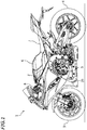
- FIG. 1 is a left side view showing the motorcycle 1 according to the present embodiment.
- the motorcycle 1 includes a vehicle frame 2, an internal combustion engine (hereinafter referred to as the engine) 5 supported on the vehicle frame 2, a front wheel 3, a rear wheel 4 driven by the engine 5, a fuel tank 6, a sheet 7, and a handle 8.
- the engine an internal combustion engine
- the front wheel 3 a rear wheel 4 driven by the engine 5
- a fuel tank 6 a sheet 7, and a handle 8.
- the handle 8 includes an accelerator grip 9, which is an example of an accelerator.
- the accelerator grip 9 is configured to be turned by the right hand of the passenger.
- the handle 8 further includes a left grip 10 held by the left hand of the passenger, a clutch lever 11 arranged forward of the left grip 10, and a brake lever 12 arranged forward of the accelerator grip 9.
- the engine 5 includes a main shaft 26, a drive shaft 27, a clutch 28, and a transmission 30.
- the clutch 28 is linked to a crankshaft 15 and the main shaft 26. With the clutch 28 engaged, a torque can be transmitted between the crankshaft 15 and the main shaft 26. With the clutch 28 disengaged, a torque cannot transmitted between the crankshaft 15 and the main shaft 26.
- the transmission 30 is a multi-gear transmission having a plurality of gears.
- the transmission 30 includes a plurality of drive gears 31 attached to the main shaft 26, a plurality of driven gears 32 attached to the drive shaft 27, a shift fork 33 that moves the drive gear 31 or the driven gear 32 in the axial direction, and a shift cam 34 that moves the shift fork 33 in the axial direction.
- the engine 5 can be a single-cylinder engine, it is a multi-cylinder engine in the present embodiment.
- the engine 5 is a four-cylinder engine including four cylinders 13.
- FIG. 3 a diagram schematically showing the configuration of each cylinder of the engine 5.
- the engine 5 includes a piston 14 arranged inside the cylinder 13, the crankshaft 15 linked to the piston 14, a combustion chamber 16, an intake passage 18 connected to the combustion chamber 16 through an intake port 17, an exhaust passage 20 connected to the combustion chamber 16 through an exhaust port 19, an intake valve 21 that covers the intake port 17 so that it can open/close the intake port 17, an exhaust valve 22 that covers the exhaust port 19 so that it can open/close the exhaust port 19, an electronic throttle valve 23 provided in the intake passage 18, a fuel injector 24 provided in the intake passage 18, and an ignitor 25.
- the electronic throttle valve 23 refers to a throttle valve that is actuated by an electric actuator.
- the engine 5 according to the present embodiment includes a motor 35 linked to the electronic throttle valve 23.
- the motor 35 is an example of an electric actuator that actuates the electronic throttle valve 23. Note however that an electric actuator is not limited to the motor 35.
- the motorcycle 1 includes an electronic control unit (hereinafter referred to as the ECU) 40.
- the ECU 40 includes a CPU, a ROM and a RAM.
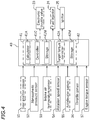
- the ECU 40 functions as an engine controller 41 that performs an engine control and as an engine brake controller 42 that performs an engine brake control (see FIG. 4 ).
- the ECU 40 includes the engine controller 41 and the engine brake controller 42.
- the motorcycle 1 includes a gear position sensor 51 that detects the gear (hereinafter referred to as the gear position) of the transmission 30, an atmospheric pressure sensor 52 that detects the atmospheric pressure, an intake air temperature sensor 53 that detects the intake air temperature of the engine 5, a rotation speed sensor 54 that detects the rotation speed (hereinafter referred to as the engine rotation speed) of the crankshaft 15, an accelerator sensor 55 that detects the amount of operation of the accelerator grip 9 (hereinafter referred to as the accelerator operation amount), and a throttle sensor 56 that detects the opening of the electronic throttle valve 23 (hereinafter referred to as the throttle opening).
- the ECU 40 is communicably connected to these sensors 51 to 56, the motor 35, the fuel injector 24 and the ignitor 25.
- the ECU 40 controls the motor 35, the fuel injector 24 and the ignitor 25 based on the detection results of these sensors 51 to 56.
- the engine controller 41 includes a calculator 41A that calculates the target torque based at least on the accelerator operation amount detected by the accelerator sensor 55, and a controller 41C that controls the electronic throttle valve 23, the fuel injector 24 and the ignitor 25 so that the torque of the engine 5 (hereinafter referred to as the engine torque) is equal to the target torque.
- the engine torque takes a positive value while the engine 5 is outputting a torque to the outside (herein, the rear wheel 4), and takes a negative value while a torque is input to the engine 5 from outside.
- the engine torque is greater than zero while the motorcycle 1 is accelerating, and the engine torque is less than zero while the motorcycle 1 is decelerating.
- the motorcycle 1 includes an engine torque sensor 57 that detects the engine torque (see FIG. 4 ).
- the engine torque sensor 57 is a device that detects the engine torque directly or indirectly, and there is no limitation on the configuration or the detection method thereof.
- the "detection of the engine torque" as used herein includes presuming the engine torque.
- the engine torque sensor 57 may be implemented as a single sensor attached to the crankshaft 15, or the like, and may directly detect the engine torque.
- the engine torque sensor 57 may be implemented as a device that calculates the engine torque based on, for example, the engine rotation speed and the throttle opening, and may indirectly detect the engine torque. By performing the calculation described above, the ECU 40 may function as the engine torque sensor.
- the engine brake controller 42 controls the degree of engine braking, which is actuated in response to the engine torque becoming less than zero. In the present embodiment, it is possible to select from three modes of engine brake control. Specifically, it is possible to select one of the normal mode in which the degree of engine braking is not reduced, the first reduced mode in which the degree of engine braking is reduced, and the second reduced mode in which engine braking is more reduced than in the first reduced mode.
- the motorcycle 1 includes a mode setter 36 for setting a mode of engine brake control. As shown in FIG. 2 , the mode setter 36 includes a mode selection switch 36A.
- the mode selection switch 36A is operated by the passenger.
- the mode selection switch 36A may be arranged on the side of the accelerator grip 9, for example. Note however that there is no particular limitation to the position of the mode selection switch 36A.
- the mode selection switch 36A may be a push switch or may be a switch of any other type.
- FIG. 5 is a diagram illustrating an engine brake control according to the present embodiment.
- the horizontal axis represents the accelerator operation amount A and the vertical axis represents the throttle opening S.
- Am represents the accelerator operation amount when the engine torque is zero.
- the engine torque is greater than zero in the region where A>Am, and the engine torque is less than zero in the region where A ⁇ Am.
- M0 denotes the normal mode
- M1 denotes the first reduced mode
- M2 denotes the second reduced mode.
- the engine brake control according to the present embodiment is a control that is performed only when the engine torque is less than zero. In the region where the engine torque is greater than or equal to zero, a similar engine control is performed in the normal mode, in the first reduced mode and in the second reduced mode.
- the characteristic curve of the normal mode M0, the characteristic curve of the first reduced mode M1 and the characteristic curve of the second reduced mode M2 do not coincide with each other in the region where the engine torque is less than zero (the region where A ⁇ Am), but coincide with each other in the region where the engine torque is greater than or equal to zero (the region where A ⁇ Am).
- the engine brake controller 42 includes a target torque corrector 42A that corrects the target torque while in the first reduced mode or the second reduced mode. While in the first reduced mode, the target torque corrector 42A corrects the target torque by adding a first additive torque to the target torque when the engine torque is less than zero. This increases the target torque, and the engine torque becomes higher than in the normal mode. As shown in FIG. 5 , in the region where the engine torque is less than zero, the throttle opening S in the first reduced mode M1 is larger than the throttle opening S in the normal mode M0. Thus, the degree of engine braking is reduced.
- the target torque corrector 42A corrects the target torque by adding a second additive torque to the target torque when the engine torque is less than zero.
- the second additive torque is greater than the first additive torque. This increases the target torque even more than in the first reduced mode, and the engine torque becomes even higher than in the first reduced mode.
- the throttle opening S in the second reduced mode M2 is larger than the throttle opening S in the first reduced mode M1.
- the degree of engine braking is further reduced.
- the first additive torque and the second additive torque are set so as to be smaller as the accelerator operation amount becomes larger. Also, as shown in FIG. 5 , the first additive torque and the second additive torque are set so that the throttle opening S is larger as the accelerator operation amount A increases. The throttle opening S increases monotonously with the increase in the accelerator operation amount A. According to the present embodiment, the accelerator operation by the passenger feels matching with the behavior of the engine torque, thereby achieving a desirable driveability.
- the engine controller 41 includes a storage 41 M.
- the storage 41M stores a target torque map (see FIG. 6 ) that defines the relationship between the engine rotation speed N, the throttle opening S and the target torque T.
- the target torque T is corrected by adding an additive torque to the target torque T.
- the additive torque to be the reference (hereinafter referred to as the reference additive torque) is set for each gear position.
- the engine brake controller 42 includes a storage 42M.
- the storage 42M is an example of the additive torque storage device, and stores an additive torque map (see FIG. 7 ) that defines the relationship between the gear position G, the engine rotation speed N and the reference additive torque TA.
- the storage 42M is also an example of the correction coefficient storage device, and stores a correction coefficient map (see FIG. 8 ) that defines the relationship between the engine rotation speed N, the accelerator operation amount A and the correction coefficient K.
- the correction coefficient K is for such an adjustment that the additive torque becomes smaller as the accelerator operation amount A becomes larger.
- the correction coefficient K is a number that is 0 or more and 1 or less, and is set so as to be smaller as the accelerator operation amount A becomes larger. For example, K31>K32>K33>K34>K35 in FIG. 8 .
- the calculator 41A of the engine controller 41 calculates the target torque T from the engine rotation speed N detected by the rotation speed sensor 54 and the throttle opening S detected by the throttle sensor 56 based on the information of the target torque map of FIG. 6 .
- the target torque is T33. Note that while the motorcycle 1 is decelerating, i.e., in the region where the engine torque is less than zero, the target torque T takes a negative value.
- FIG. 9 is a control block diagram for this calculation example.
- the target torque corrector 42A of the engine brake controller 42 calculates the reference additive torque TA from the gear position G detected by the gear position sensor 51 and the engine rotation speed N detected by the rotation speed sensor 54 based on the information of the additive torque map of FIG. 7 .
- the target torque corrector 42A functions as a first calculator 42A1. For example, as shown in FIG. 7 , where the gear position is 1 and the engine rotation speed is N3, the reference additive torque is TA13.
- the reference additive torque takes a positive value.
- the target torque corrector 42A calculates the correction coefficient K from the engine rotation speed N detected by the rotation speed sensor 54 and the accelerator operation amount A detected by the accelerator sensor 55 based on the information of the correction coefficient map of FIG. 8 .
- the target torque corrector 42A functions as a second calculator 42A2.
- the correction coefficient is K32.
- the correction coefficient K is a number that is 0 or more and 1 or less.
- the target torque corrector 42A obtains the first additive torque by multiplying the reference additive torque TA by the correction coefficient K.
- the target torque corrector 42A functions as a third calculator 42A3.
- the reference additive torque is TA13 and the correction coefficient is K32
- the first additive torque H1 K32 x TA13.
- the target torque corrector 42A corrects the target torque T by adding the first additive torque H1 to the target torque T.
- T denotes the uncorrected target torque
- T' denotes the corrected target torque
- T' T+H1 holds.
- the controller 41C of the engine controller 41 controls the motor 35, the fuel injector 24 and the ignitor 25 so that the engine torque coincides with the corrected target torque T'.
- the controller 41C of the engine controller 41 controls the motor 35, the fuel injector 24 and the ignitor 25 so that the engine torque coincides with the uncorrected target torque T.
- the calculation of the reference additive torque TA may use the atmospheric pressure detected by the atmospheric pressure sensor 52 and the intake air temperature detected by the intake air temperature sensor 53. That is, the reference additive torque TA may be corrected based on the atmospheric pressure and the intake air temperature. Similarly, the calculation of the correction coefficient K may use information of the atmospheric pressure and the intake air temperature. Where the engine 5 is a water-cooled engine, information of the coolant temperature may be used.
- the second additive torque can be calculated similarly.
- the storage 42M of the engine brake controller 42 may store, as maps for use in the second reduced mode, an additive torque map and a correction coefficient map that are different from those in the first reduced mode. That is, the first reduced mode and the second reduced mode may use different additive torque maps and different correction coefficient maps. Alternatively, the first reduced mode and the second reduced mode may use the same additive torque map and different correction coefficient maps.
- calculator 41A and the controller 41C of the engine controller 41 and the target torque corrector 42A of the engine brake controller 42 are shown in FIG. 4 to be separate from each other, they may be implemented by the same arithmetic unit or may be implemented by different arithmetic units.
- the storage 41 M of the engine controller 41 and the storage 42M of the engine brake controller 42 may be implemented by the same storage device or may be implemented by different storage devices.
- the engine torque can be changed by adjusting the opening of the electronic throttle valve 23, the amount of injection of the fuel injector 24 and the ignition timing of the ignitor 25.
- the fuel injector 24 in the normal mode and in the first reduced mode, the fuel injector 24 does not inject fuel and the opening of the electronic throttle valve 23 is adjusted to control the degree of engine braking while the engine rotation speed N is greater than or equal to Nc1.
- the fuel injector 24 injects fuel while the engine rotation speed N is greater than or equal to Nc2
- the fuel injector 24 does not inject fuel while the engine rotation speed N is greater than or equal to Nc1 and less than Nc2.
- the fuel injector 24 injects fuel while the engine rotation speed is high (when it is greater than or equal to Nc2), and it is possible to significantly reduce the engine brake.
- the fuel injection from the fuel injector 24 is stopped and the opening of the electronic throttle valve 23 is set to a predetermined opening Ss while in the normal mode.
- the specific condition while in the first reduced mode, the fuel injection from the fuel injector 24 is stopped and the opening of the electronic throttle valve 23 is set to a first opening Ss1, which is larger than the predetermined opening Ss.
- the specific condition while in the second reduced mode, the fuel is injected from the fuel injector 24 and the opening of the electronic throttle valve 23 is set to a second opening Ss2, which is smaller than the first opening Ss1.
- the mode of engine brake control may be switched while the motorcycle 1 is running. Note however that depending on the driving state, changing the mode while the motorcycle 1 is running may detract from the driveability.
- the mode of engine brake control can be changed while the motorcycle 1 is running only if a predetermined condition (hereinafter referred to as the mode switching condition) is satisfied.
- the mode setter 36 includes a determiner 36B and a mode switcher 36C, in addition to the mode selection switch 36A described above.
- the ECU 40 functions as the determiner 36B and the mode switcher 36C.
- the determiner 36B determines whether the mode switching condition is satisfied.
- the mode switcher 36C changes the mode in accordance with the operation performed on the mode selection switch 36A. For example, assume that while the motorcycle 1 is running, the passenger operates the mode selection switch 36A so as to give an instruction to switch from the normal mode to the first reduced mode. In this case, the determiner 36B determines whether the mode switching condition is satisfied. When it is determined that the mode switching condition is satisfied, the mode switcher 36C switches the mode from the normal mode to the first reduced mode. When it is determined that the mode switching condition is not satisfied, the mode switcher 36C does not switch the mode but maintains the normal mode.
- the mode switching condition may include one of the first to sixth conditions below, for example.
- the condition is to meet all of the first to sixth conditions.
- the bank angle refers to the inclination angle of the motorcycle 1 from the vertical line.
- the traction control is a control for preventing wheelspin of the rear wheel 4 of the motorcycle 1 when starting or when rapidly accelerating, for example. That is, it is a control for preventing the slip of the driving wheel against the road surface.
- the slide control is a control for preventing the motorcycle 1 from skidding sideway.
- the lift control is a control for preventing the front wheel 3 from being lifted while accelerating.
- the switching of the mode may be allowed only while the motorcycle 1 is standing. That is, the switching of the mode may be prohibited while the motorcycle 1 is running.
- the determiner 36B may be configured to determine whether the motorcycle 1 is running, and determine that the mode switching condition is not satisfied while the motorcycle 1 is running.
- the present engine brake control is performed when the engine torque is less than zero (see FIG. 5 ).
- the present engine brake control is independent of the engine control that is performed when the engine torque is greater than or equal to zero. Also for this engine control, it may be possible to select from among some modes. For example, as shown in FIG. 12 , for the engine control, it may be possible to select from the reference mode D2, the high acceleration mode D1 in which the degree of acceleration for the accelerator operation amount is greater than that in the reference mode D2, and the low acceleration mode D3 in which the degree of acceleration for the accelerator operation amount is less than that in the reference mode D2.
- the present engine brake control is independent of the engine control, it is possible to select any of the normal mode M0, the first reduced mode M1 and the second reduced mode M2 as the engine brake control, while in any of the high acceleration mode D1, the reference mode D2 and the low acceleration mode D3, in the present embodiment.
- the characteristic curve of D1 is obtained in the region where the engine torque is greater than or equal to zero, whereas the characteristic curve of M0 is obtained in the region where the engine torque is less than zero.
- the characteristic curve of D1 is obtained in the region where the engine torque is greater than or equal to zero, whereas the characteristic curve of M1 is obtained in the region where the engine torque is less than zero.
- the configuration of the motorcycle 1 and the details of the engine brake control according to the present embodiment have been described above. Since the motorcycle 1 is lighter than an automobile, the driveability is influenced more significantly by subtle degrees of engine braking. However, according to the present embodiment, it is possible to subtly adjust the degree of engine braking in accordance with the liking of the passenger.
- the mode of engine brake control By selecting the first reduced mode, it is possible to reduce the degree of engine braking than in the normal mode. By selecting the second reduced mode, it is possible to further reduce the degree of engine braking.
- the degree by which engine braking is reduced decreases as the accelerator operation amount increases.
- the accelerator operation by the passenger feels matching with the behavior of the engine torque. Therefore, it is possible to realize a desirable driveability.
- the number of modes is relatively large, realizing a wide variety of mode changes, and it is possible to sufficiently improve the driveability.
- a similar control is performed when the engine torque is greater than or equal to zero. It is possible to change only the degree of engine braking, with no change to the control while accelerating. Therefore, it is possible to improve the driveability while engine braking is actuated without detracting from the driveability while accelerating.
- the change of mode is prohibited if the mode switching condition is not satisfied. This prohibits such mode changes that may detract from the driveability. Thus, it is possible to maintain a desirable driveability even when the mode is changed.
- the throttle opening S is controlled based on the accelerator operation amount A (see FIG. 5 ), and the correction coefficient K is calculated based on the accelerator operation amount A (see FIG. 8 ).
- a rider torque to be described below is used instead of the accelerator operation amount.
- the passenger operates the accelerator grip 9 to adjust the engine torque.
- the rider torque is a parameter obtained by converting the accelerator operation amount into the engine torque while taking the driving state of the motorcycle 1 into consideration.
- Parameters representing the driving state include information such as the engine rotation speed, the throttle opening and the gear position.
- the rider torque is determined by the accelerator operation amount, the engine rotation speed, the throttle opening and the gear position. Note that the rider torque may be corrected by using information such as the atmospheric pressure, the intake air temperature and the coolant temperature.
- controlling the throttle opening S based on the rider torque is generally equal to controlling the throttle opening S based on the accelerator operation amount.
- correcting the target torque based on the rider torque is generally equal to correcting the target torque based on the accelerator operation amount.
- the correction coefficient map defines the relationship between the engine rotation speed N, the accelerator operation amount A and the correction coefficient K in the first embodiment (see FIG. 8 )
- the correction coefficient map according to the second embodiment is a map that defines the relationship between the engine rotation speed N, the rider torque and the correction coefficient K.
- the horizontal axis of the characteristic curve represents the accelerator operation amount A in the first embodiment
- the horizontal axis of the characteristic curve represents the rider torque in the second embodiment.
- the number of modes is not limited to three.
- the number of modes of engine brake control may be four or more.
- the target torque corrector 42A of the engine brake controller 42 while in the third reduced mode, the target torque is corrected by adding a third additive torque to the target torque when the engine torque is less than zero.
- the third additive torque is greater than the second additive torque.
- the third additive torque is set so as to be smaller as the accelerator operation amount becomes larger so that the throttle opening increases as the accelerator operation amount increases.
- the injection from the fuel injector 24 is stopped when the engine rotation speed is in a predetermined range, but the fuel is injected from the fuel injector 24 when the engine rotation speed is below the predetermined range or above the predetermined range.
- the fuel is injected from the fuel injector 24, and the opening of the electronic throttle valve 23 is set to a third opening Ss3, which is larger than the first opening Ss1.
- the variety of modes of engine brake control is further increased, and the passenger can select a mode that matches the liking of the passenger. Therefore, it is possible to further improve the driveability.
- the fourth reduced mode there may be a reduced mode (hereinafter referred to as the fourth reduced mode) in which engine braking is reduced relative to the normal mode but is not as much reduced as in the first reduced mode.
- the target torque corrector 42A of the engine brake controller 42 while in the fourth reduced mode, the target torque is corrected by adding a fourth additive torque to the target torque when the engine torque is less than zero.
- the fourth additive torque is smaller than the first additive torque.
- the fourth additive torque is set so as to be smaller as the accelerator operation amount becomes larger so that the throttle opening increases as the accelerator operation amount increases.
- the injection from the fuel injector 24 is stopped.
- the opening of the electronic throttle valve 23 is set to a fourth opening Ss4, which is larger than the predetermined opening Ss and less than the first opening Ss1.
- the variety of modes of engine brake control is further increased, and the passenger can select a mode that matches the liking of the passenger. Therefore, it is possible to further improve the driveability.
- the engine brake control described above is performed for each cylinder 13 (see FIG. 3 ).
- the engine torque can be adjusted by only operating some cylinders 13 while having the other cylinders 13 inoperative.
- the fifth embodiment is similar to any of the first to fourth embodiments, wherein there is a mode (hereinafter referred to as the fifth reduced mode) in which engine braking is reduced by only operating some cylinders 13 while having the other cylinders 13 inoperative.
- the target torque corrector 42A of the engine brake controller 42 while in the fifth reduced mode, the target torque is corrected by adding a fifth additive torque to the target torque when the engine torque is less than zero.
- the fifth additive torque may be greater than or less than the first additive torque.
- the fifth additive torque is set so as to be smaller as the accelerator operation amount becomes larger so that the throttle opening increases as the accelerator operation amount increases.
- the fuel is injected from the fuel injector 24 for some cylinders 13 while stopping the fuel injection from the fuel injector 24 for the other cylinders 13.
- the variety of modes of engine brake control is further increased, and the passenger can select a mode that matches the liking of the passenger. Therefore, it is possible to further improve the driveability.
- an engine brake control is performed across the entire region where the engine torque is less than zero.
- an engine brake control is performed across the entire region where the accelerator operation amount A is less than Am.
- An engine brake control may be performed only in a partial region where the engine torque is less than zero.
- an engine brake control may be performed only in a partial region where the accelerator operation amount A is less than Am.
- the characteristic curves of the normal mode M0, the first reduced mode M1 and the second reduced mode M2 merge together at a point where the accelerator operation amount A is equal to Am. However, these characteristic curves may merge at a point where the accelerator operation amount A is less than Am.
- a straddled vehicle refers to a vehicle that is straddled by a passenger. While a motorcycle is an example straddled vehicle, a straddled vehicle is not limited to a motorcycle.
- a straddled vehicle may include an auto tricycle, an ATV (All Terrain Vehicle), and the like, as well as a motorcycle.
- the internal combustion engine is not limited to a multi-cylinder engine but may be a single-cylinder engine.
- the internal combustion engine may be a water-cooled internal combustion engine or may be an air-cooled internal combustion engine.
Landscapes
- Engineering & Computer Science (AREA)
- Mechanical Engineering (AREA)
- Chemical & Material Sciences (AREA)
- Combustion & Propulsion (AREA)
- General Engineering & Computer Science (AREA)
- Transportation (AREA)
- Control Of Throttle Valves Provided In The Intake System Or In The Exhaust System (AREA)
- Electrical Control Of Air Or Fuel Supplied To Internal-Combustion Engine (AREA)
- Combined Controls Of Internal Combustion Engines (AREA)
- Control Of Transmission Device (AREA)
- Output Control And Ontrol Of Special Type Engine (AREA)
- Control Of Vehicle Engines Or Engines For Specific Uses (AREA)
Abstract
Description
- The present invention relates to a straddled vehicle and to a method for controlling a straddled vehicle.
- Conventional vehicles are known in the art, with which it is possible to configure adjustments to the engine power for different amounts of operation performed on the accelerator pedal while accelerating. For example,
JP 2016-17517 A - With the vehicle disclosed in
JP 2016-17517 A - The vehicle is also capable of an engine brake control for controlling the degree of engine braking while decelerating. The vehicle is configured so that it is possible to turn ON/OFF the engine brake control. The engine brake control is provided for the purpose of eliminating awkwardness, which is felt upon actuation of engine brake when the passenger inadvertently releases the accelerator while the vehicle is running. When it is detected that the passenger was depressing the accelerator pedal and is no longer depressing the accelerator pedal, the accelerator sensor outputs a pseudo-accelerator opening signal. When the pseudo-accelerator opening signal is received, the controller device controls the degree of engine braking so that engine brake is not actuated until the accelerator pedal is depressed again or the brake pedal is depressed. This eliminates awkwardness, allowing the passenger to enjoy a smooth driveability.
- The vehicle disclosed in
JP 2016-17517 A - The throttle opening S may be controlled to be a constant value Sc when engine brake is actuated (i.e., when decelerating), as shown in
FIG. 13 , for example. Then, the throttle opening S is prevented from becoming less than Sc while an engine brake control is on. Note that the horizontal axis ofFIG. 13 represents the accelerator operation amount A, and the vertical axis thereof represents the throttle opening S. With such a control, however, when the passenger increases the accelerator operation amount A from zero, the throttle opening S does not increase until the accelerator operation amount A reaches a predetermined value Ac. Even if the accelerator is operated, the engine torque does not increase for a while. Therefore, the accelerator operation by the passenger does not feel matching with the behavior of the engine torque, failing to realize a desirable driveability. - As shown in
FIG. 14 , the throttle opening S may be controlled to be increased uniformly by a certain amount, irrespective of the accelerator operation amount A. With such a control, however, the throttle opening S for the accelerator operation amount A changes similarly in a region where the accelerator operation amount A is large as well as in a region where the accelerator operation amount A is small. However, the throttle opening S for the accelerator operation amount A is pre-configured so as to realize a desirable driveability. The driveability deteriorates if the throttle opening S changes in a region where the accelerator operation amount A is large. - It is an object of the present invention, to provide a straddled vehicle and a method for controlling a straddled vehicle that can realizes an improved driveability while engine braking is actuated. According to the present invention said object is solved by a straddled vehicle having the features of
independent claim 1. Moreover, According to the present invention said object is solved by method for controlling a straddled vehicle having the features ofindependent claim 13. Preferred embodiments are laid down in the dependent claims. - Accordingly, a straddled vehicle disclosed herein includes: an internal combustion engine including an electronic throttle valve provided in an intake passage and a fuel injector that injects fuel; an accelerator that is operated by a passenger; an accelerator sensor that detects an amount of operation of the accelerator; an engine torque sensor that detects a torque of the internal combustion engine; an engine controller device that controls the torque of the internal combustion engine; an engine brake controller device that controls a degree of engine braking, which is actuated by the torque of the internal combustion engine becoming less than zero; and a mode setter that selectively sets one of at least a normal mode in which the degree of engine braking is not reduced and a first reduced mode in which the degree of engine braking is reduced. The engine controller device includes a calculator that calculates a target torque based at least on the amount of operation of the accelerator, and a controller that controls the electronic throttle valve and the fuel injector so that the torque of the internal combustion engine is equal to the target torque. The engine brake controller device includes a target torque corrector that corrects the target torque by adding a first additive torque to the target torque, which is calculated by the calculator when the torque of the internal combustion engine is less than zero while in the first reduced mode. The first additive torque is set so as to be smaller as the amount of operation of the accelerator becomes larger so that an opening of the electronic throttle valve increases as the amount of operation of the accelerator increases.
- With the straddled vehicle described above, by setting the first reduced mode, it is possible to reduce the degree of engine braking relative to the normal mode. It is possible to realize a desirable engine brake for a passenger who wishes to reduce the degree of engine braking. In the first reduced mode, the degree by which engine braking is reduced decreases as the amount of operation of the accelerator increases. Thus, the accelerator operation by the passenger feels matching with the behavior of the engine torque, thereby realizing a desirable driveability.
- According to one preferred embodiment, the engine controller device is configured to perform a similar control when the torque of the internal combustion engine is greater than or equal to zero while in the normal mode and while in the first reduced mode.
- According to the embodiment described above, it is possible to change only the degree of engine braking, with no change to the control while accelerating. Therefore, it is possible to improve the driveability while engine braking is actuated without detracting from the driveability while accelerating.
- According to one preferred embodiment, the engine controller device is configured to stop fuel injection from the fuel injector and set the opening of the electronic throttle valve to a predetermined opening when the torque of the internal combustion engine is less than zero and a rotation speed of the internal combustion engine is equal to a predetermined rotation speed while in the normal mode; and the engine controller device is configured to stop fuel injection from the fuel injector and set the opening of the electronic throttle valve to a first opening, which is larger than the predetermined opening, when the torque of the internal combustion engine is less than zero and a rotation speed of the internal combustion engine is equal to the predetermined rotation speed while in the first reduced mode.
- According to the embodiment described above, when the rotation speed of the internal combustion engine is equal to a predetermined rotation speed, in the normal mode, it is possible to realize a relatively strong engine brake by stopping the fuel injection from the fuel injector. On the other hand, in the first reduced mode, the opening of the electronic throttle valve is increased relative to the normal mode, thereby reducing engine braking.
- According to one preferred embodiment, the mode setter is configured to selectively set one of at least the normal mode, the first reduced mode and a second reduced mode in which the degree of engine braking is reduced. The target torque corrector is configured to correct the target torque by adding a second additive torque, which is larger than the first additive torque, to the target torque calculated by the calculator when the torque of the internal combustion engine is less than zero while in the second reduced mode. The second additive torque is set so as to be smaller as the amount of operation of the accelerator becomes larger so that the opening of the electronic throttle valve increases as the amount of operation of the accelerator increases.
- According to the embodiment described above, it is possible to select from at least three modes, i.e., the normal mode, the first reduced mode and the second reduced mode. The variety of mode changes is increased, and it is possible to further improve the driveability.
- According to one preferred embodiment, the engine controller device is configured to stop fuel injection from the fuel injector and set the opening of the electronic throttle valve to a predetermined opening when the torque of the internal combustion engine is less than zero and a rotation speed of the internal combustion engine is equal to a predetermined rotation speed while in the normal mode; the engine controller device is configured to stop fuel injection from the fuel injector and set the opening of the electronic throttle valve to a first opening, which is larger than the predetermined opening, when the torque of the internal combustion engine is less than zero and a rotation speed of the internal combustion engine is equal to the predetermined rotation speed while in the first reduced mode; and the engine controller device is configured to allow fuel to be injected from the fuel injector and set the opening of the electronic throttle valve to a second opening, which is smaller than the first opening, when the torque of the internal combustion engine is less than zero and a rotation speed of the internal combustion engine is equal to the predetermined rotation speed while in the second reduced mode.
- When the fuel injection from the fuel injector is stopped, there is a limit to the reduction of the engine brake by increasing the opening of the electronic throttle valve. However, according to the embodiment described above, in the second reduced mode, fuel is injected from the fuel injector, and it is possible to more reduce engine braking.
- According to one preferred embodiment, the mode setter is configured to selectively set one of at least the normal mode, the first reduced mode, the second reduced mode and a third reduced mode in which the degree of engine braking is reduced. The target torque corrector is configured to correct the target torque by adding a third additive torque, which is larger than the second additive torque, to the target torque calculated by the calculator when the torque of the internal combustion engine is less than zero while in the third reduced mode. The third additive torque is set so as to be smaller as the amount of operation of the accelerator becomes larger so that the opening of the electronic throttle valve increases as the amount of operation of the accelerator increases. The engine controller device is configured to allow fuel to be injected from the fuel injector and set the opening of the electronic throttle valve to a third opening, which is larger than the first opening, when the torque of the internal combustion engine is less than zero and the rotation speed of the internal combustion engine is equal to the predetermined rotation speed while in the third reduced mode.
- According to the embodiment described above, it is possible to select from at least four modes, i.e., the normal mode, the first reduced mode, the second reduced mode and the third reduced mode. The variety of mode changes is increased, and it is possible to further improve the driveability.
- According to one preferred embodiment, the mode setter is configured to selectively set one of at least the normal mode, the first reduced mode and a fourth reduced mode in which the degree of engine braking is reduced. The target torque corrector is configured to correct the target torque by adding a fourth additive torque, which is smaller than the first additive torque, to the target torque calculated by the calculator when the torque of the internal combustion engine is less than zero while in the fourth reduced mode. The fourth additive torque is set so as to be smaller as the amount of operation of the accelerator becomes larger so that the opening of the electronic throttle valve increases as the amount of operation of the accelerator increases. The engine controller device is configured to stop fuel injection from the fuel injector and set the opening of the electronic throttle valve to a fourth opening, which is larger than the predetermined opening and smaller than the first opening, when the torque of the internal combustion engine is less than zero and the rotation speed of the internal combustion engine is equal to the predetermined rotation speed while in the fourth reduced mode.
- According to the embodiment described above, it is possible to select from at least four modes, i.e., the normal mode, the first reduced mode, the second reduced mode and the fourth reduced mode. The variety of mode changes is increased, and it is possible to further improve the driveability.
- According to one preferred embodiment, the internal combustion engine includes a plurality of cylinders. The fuel injector is configured to inject fuel to an air supplied to one of the plurality of cylinders. The internal combustion engine includes another fuel injector that injects fuel to an air supplied to another one of the plurality of cylinders. The mode setter is configured to selectively set one of at least the normal mode, the first reduced mode and a fifth reduced mode in which the degree of engine braking is reduced. The target torque corrector is configured to correct the target torque by adding a fifth additive torque to the target torque calculated by the calculator when the torque of the internal combustion engine is less than zero while in the fifth reduced mode. The fifth additive torque is set so as to be smaller as the amount of operation of the accelerator becomes larger so that the opening of the electronic throttle valve increases as the amount of operation of the accelerator increases. The engine controller device is configured to allow fuel to be injected from one of the fuel injectors while stopping fuel injection from the other fuel injector when the torque of the internal combustion engine is less than zero and the rotation speed of the internal combustion engine is equal to the predetermined rotation speed while in the fifth reduced mode.
- According to the embodiment described above, it is possible to select from at least three modes, i.e., the normal mode, the first reduced mode and the fifth reduced mode. The variety of mode changes is increased, and it is possible to further improve the driveability.
- According to one preferred embodiment, the mode setter includes: a mode selection switch that is operated by the passenger for selecting a mode; a determining device that determines whether to allow or prohibit a mode change based on a predetermined condition, when the mode selection switch is operated; and a mode switching device that changes the mode in accordance with the operation performed on the mode selection switch when it is determined by the determining device that the condition is satisfied, and that does not change the mode, irrespective of the operation performed on the mode selection switch, when it is determined by the determining device that the condition is not satisfied. The condition may include at least one of the torque of the internal combustion engine being greater than zero and a bank angle being less than or equal to a predetermined angle. The condition may include at least one of a traction control being not performed, a slide control being not performed and a lift control being not performed.
- Depending on the driving state, changing the mode while running may detract from the driveability. According to the embodiment described above, such mode changes that may detract from the driveability are prohibited, and it is therefore possible to maintain a desirable driveability.
- According to one preferred embodiment, the straddled vehicle includes a transmission having a plurality of gear positions; a gear position sensor that detects a gear position of the transmission; a rotation speed sensor that detects a rotation speed of the internal combustion engine; and a throttle sensor that detects an opening of the electronic throttle valve. The engine brake controller device includes an additive torque storage device that stores information of a predetermined relationship between a gear position of the transmission, the rotation speed of the internal combustion engine and a reference additive torque, and a correction coefficient storage device that stores information of a predetermined relationship between the rotation speed of the internal combustion engine, the amount of operation of the accelerator and a correction coefficient. The target torque corrector includes: a first calculator that calculates the reference additive torque from the rotation speed of the internal combustion engine detected by the rotation speed sensor and the gear position of the transmission detected by the gear position sensor based on the information stored in the additive torque storage device; a second calculator that calculates the correction coefficient from the rotation speed of the internal combustion engine detected by the rotation speed sensor and the amount of operation of the accelerator detected by the accelerator sensor based on the information stored in the correction coefficient storage device; and a third calculator that calculates the first additive torque by multiplying the reference additive torque calculated by the first calculator by the correction coefficient calculated by the second calculator.
- According to the embodiment described above, it is possible to relatively easily perform the engine brake control described above.
- According to the present invention, it is possible to provide a straddled vehicle that realizes an improved driveability while engine braking is actuated.
-
-
FIG. 1 is a left side view showing a motorcycle according to an embodiment. -
FIG. 2 is a conceptual diagram showing a handle and a main part of an internal combustion engine. -
FIG. 3 is a conceptual diagram showing a main part of an internal combustion engine. -
FIG. 4 is a block diagram showing a control system of a motorcycle. -
FIG. 5 is a diagram illustrating an engine brake control, representing the throttle opening relative to the accelerator operation amount. -
FIG. 6 is a diagram representing a target torque map. -
FIG. 7 is a diagram representing an additive torque map. -
FIG. 8 is a diagram representing a correction coefficient map. -
FIG. 9 is a control block diagram for a calculation example with a first additive torque. -
FIG. 10 is a diagram showing the relationship between the engine rotation speed and the ON/OFF of the fuel injection for different engine brake control modes. -
FIG. 11 is a block diagram showing a mode setter. -
FIG. 12 is a diagram illustrating an engine brake control and an engine control, representing the throttle opening relative to the accelerator operation amount. -
FIG. 13 is a diagram representing the throttle opening relative to the accelerator operation amount for an engine brake control where the throttle opening is a constant value. -
FIG. 14 is a diagram representing the throttle opening relative to the accelerator operation amount for an engine brake control where the throttle opening is increased uniformly by a certain amount, irrespective of the accelerator operation amount. - A preferred embodiment will now be described with reference to the drawings.
FIG. 1 is a left side view showing themotorcycle 1 according to the present embodiment. - As shown in
FIG. 1 , themotorcycle 1 includes avehicle frame 2, an internal combustion engine (hereinafter referred to as the engine) 5 supported on thevehicle frame 2, afront wheel 3, arear wheel 4 driven by theengine 5, afuel tank 6, asheet 7, and ahandle 8. - As schematically shown in
FIG. 2 , thehandle 8 includes anaccelerator grip 9, which is an example of an accelerator. Theaccelerator grip 9 is configured to be turned by the right hand of the passenger. Thehandle 8 further includes aleft grip 10 held by the left hand of the passenger, aclutch lever 11 arranged forward of theleft grip 10, and abrake lever 12 arranged forward of theaccelerator grip 9. - The
engine 5 includes amain shaft 26, adrive shaft 27, a clutch 28, and atransmission 30. The clutch 28 is linked to acrankshaft 15 and themain shaft 26. With the clutch 28 engaged, a torque can be transmitted between thecrankshaft 15 and themain shaft 26. With the clutch 28 disengaged, a torque cannot transmitted between thecrankshaft 15 and themain shaft 26. Thetransmission 30 is a multi-gear transmission having a plurality of gears. Thetransmission 30 includes a plurality of drive gears 31 attached to themain shaft 26, a plurality of drivengears 32 attached to thedrive shaft 27, ashift fork 33 that moves thedrive gear 31 or the drivengear 32 in the axial direction, and ashift cam 34 that moves theshift fork 33 in the axial direction. - While the
engine 5 can be a single-cylinder engine, it is a multi-cylinder engine in the present embodiment. In the present embodiment, theengine 5 is a four-cylinder engine including fourcylinders 13.FIG. 3 a diagram schematically showing the configuration of each cylinder of theengine 5. Theengine 5 includes apiston 14 arranged inside thecylinder 13, thecrankshaft 15 linked to thepiston 14, acombustion chamber 16, anintake passage 18 connected to thecombustion chamber 16 through anintake port 17, anexhaust passage 20 connected to thecombustion chamber 16 through anexhaust port 19, anintake valve 21 that covers theintake port 17 so that it can open/close theintake port 17, anexhaust valve 22 that covers theexhaust port 19 so that it can open/close theexhaust port 19, anelectronic throttle valve 23 provided in theintake passage 18, afuel injector 24 provided in theintake passage 18, and anignitor 25. - The
electronic throttle valve 23 refers to a throttle valve that is actuated by an electric actuator. As shown inFIG. 2 , theengine 5 according to the present embodiment includes amotor 35 linked to theelectronic throttle valve 23. Themotor 35 is an example of an electric actuator that actuates theelectronic throttle valve 23. Note however that an electric actuator is not limited to themotor 35. - As shown in
FIG. 3 , themotorcycle 1 includes an electronic control unit (hereinafter referred to as the ECU) 40. Although not shown in the figure, theECU 40 includes a CPU, a ROM and a RAM. Although the details will be described later, theECU 40 functions as anengine controller 41 that performs an engine control and as anengine brake controller 42 that performs an engine brake control (seeFIG. 4 ). TheECU 40 includes theengine controller 41 and theengine brake controller 42. - As shown in
FIG. 4 , themotorcycle 1 includes agear position sensor 51 that detects the gear (hereinafter referred to as the gear position) of thetransmission 30, anatmospheric pressure sensor 52 that detects the atmospheric pressure, an intakeair temperature sensor 53 that detects the intake air temperature of theengine 5, arotation speed sensor 54 that detects the rotation speed (hereinafter referred to as the engine rotation speed) of thecrankshaft 15, anaccelerator sensor 55 that detects the amount of operation of the accelerator grip 9 (hereinafter referred to as the accelerator operation amount), and athrottle sensor 56 that detects the opening of the electronic throttle valve 23 (hereinafter referred to as the throttle opening). TheECU 40 is communicably connected to thesesensors 51 to 56, themotor 35, thefuel injector 24 and theignitor 25. TheECU 40 controls themotor 35, thefuel injector 24 and theignitor 25 based on the detection results of thesesensors 51 to 56. - The
engine controller 41 includes acalculator 41A that calculates the target torque based at least on the accelerator operation amount detected by theaccelerator sensor 55, and acontroller 41C that controls theelectronic throttle valve 23, thefuel injector 24 and theignitor 25 so that the torque of the engine 5 (hereinafter referred to as the engine torque) is equal to the target torque. Note that the engine torque takes a positive value while theengine 5 is outputting a torque to the outside (herein, the rear wheel 4), and takes a negative value while a torque is input to theengine 5 from outside. The engine torque is greater than zero while themotorcycle 1 is accelerating, and the engine torque is less than zero while themotorcycle 1 is decelerating. - The
motorcycle 1 includes anengine torque sensor 57 that detects the engine torque (seeFIG. 4 ). Theengine torque sensor 57 is a device that detects the engine torque directly or indirectly, and there is no limitation on the configuration or the detection method thereof. The "detection of the engine torque" as used herein includes presuming the engine torque. Theengine torque sensor 57 may be implemented as a single sensor attached to thecrankshaft 15, or the like, and may directly detect the engine torque. Theengine torque sensor 57 may be implemented as a device that calculates the engine torque based on, for example, the engine rotation speed and the throttle opening, and may indirectly detect the engine torque. By performing the calculation described above, theECU 40 may function as the engine torque sensor. - The
engine brake controller 42 controls the degree of engine braking, which is actuated in response to the engine torque becoming less than zero. In the present embodiment, it is possible to select from three modes of engine brake control. Specifically, it is possible to select one of the normal mode in which the degree of engine braking is not reduced, the first reduced mode in which the degree of engine braking is reduced, and the second reduced mode in which engine braking is more reduced than in the first reduced mode. Themotorcycle 1 includes amode setter 36 for setting a mode of engine brake control. As shown inFIG. 2 , themode setter 36 includes amode selection switch 36A. Themode selection switch 36A is operated by the passenger. Themode selection switch 36A may be arranged on the side of theaccelerator grip 9, for example. Note however that there is no particular limitation to the position of themode selection switch 36A. Themode selection switch 36A may be a push switch or may be a switch of any other type. -
FIG. 5 is a diagram illustrating an engine brake control according to the present embodiment. The horizontal axis represents the accelerator operation amount A and the vertical axis represents the throttle opening S. Am represents the accelerator operation amount when the engine torque is zero. The engine torque is greater than zero in the region where A>Am, and the engine torque is less than zero in the region where A<Am. M0 denotes the normal mode, M1 denotes the first reduced mode, and M2 denotes the second reduced mode. As shown inFIG. 5 , the engine brake control according to the present embodiment is a control that is performed only when the engine torque is less than zero. In the region where the engine torque is greater than or equal to zero, a similar engine control is performed in the normal mode, in the first reduced mode and in the second reduced mode. The characteristic curve of the normal mode M0, the characteristic curve of the first reduced mode M1 and the characteristic curve of the second reduced mode M2 do not coincide with each other in the region where the engine torque is less than zero (the region where A<Am), but coincide with each other in the region where the engine torque is greater than or equal to zero (the region where A≥Am). - As shown in
FIG. 4 , theengine brake controller 42 includes atarget torque corrector 42A that corrects the target torque while in the first reduced mode or the second reduced mode. While in the first reduced mode, thetarget torque corrector 42A corrects the target torque by adding a first additive torque to the target torque when the engine torque is less than zero. This increases the target torque, and the engine torque becomes higher than in the normal mode. As shown inFIG. 5 , in the region where the engine torque is less than zero, the throttle opening S in the first reduced mode M1 is larger than the throttle opening S in the normal mode M0. Thus, the degree of engine braking is reduced. - While in the second reduced mode, the
target torque corrector 42A corrects the target torque by adding a second additive torque to the target torque when the engine torque is less than zero. Note that the second additive torque is greater than the first additive torque. This increases the target torque even more than in the first reduced mode, and the engine torque becomes even higher than in the first reduced mode. As shown inFIG. 5 , in the region where the engine torque is less than zero, the throttle opening S in the second reduced mode M2 is larger than the throttle opening S in the first reduced mode M1. Thus, the degree of engine braking is further reduced. - The first additive torque and the second additive torque are set so as to be smaller as the accelerator operation amount becomes larger. Also, as shown in
FIG. 5 , the first additive torque and the second additive torque are set so that the throttle opening S is larger as the accelerator operation amount A increases. The throttle opening S increases monotonously with the increase in the accelerator operation amount A. According to the present embodiment, the accelerator operation by the passenger feels matching with the behavior of the engine torque, thereby achieving a desirable driveability. - Next, an example of a method for calculating the first additive torque will be described. As shown in
FIG. 4 , theengine controller 41 includes astorage 41 M. Thestorage 41M stores a target torque map (seeFIG. 6 ) that defines the relationship between the engine rotation speed N, the throttle opening S and the target torque T. - In the engine brake control, the target torque T is corrected by adding an additive torque to the target torque T. The additive torque to be the reference (hereinafter referred to as the reference additive torque) is set for each gear position. The
engine brake controller 42 includes astorage 42M. Thestorage 42M is an example of the additive torque storage device, and stores an additive torque map (seeFIG. 7 ) that defines the relationship between the gear position G, the engine rotation speed N and the reference additive torque TA. - As described above, the additive torque is set so as to be smaller as the accelerator operation amount becomes larger. The
storage 42M is also an example of the correction coefficient storage device, and stores a correction coefficient map (seeFIG. 8 ) that defines the relationship between the engine rotation speed N, the accelerator operation amount A and the correction coefficient K. The correction coefficient K is for such an adjustment that the additive torque becomes smaller as the accelerator operation amount A becomes larger. The correction coefficient K is a number that is 0 or more and 1 or less, and is set so as to be smaller as the accelerator operation amount A becomes larger. For example, K31>K32>K33>K34>K35 inFIG. 8 . - The
calculator 41A of theengine controller 41 calculates the target torque T from the engine rotation speed N detected by therotation speed sensor 54 and the throttle opening S detected by thethrottle sensor 56 based on the information of the target torque map ofFIG. 6 . For example, where the engine rotation speed is N3 and the throttle opening is S3, the target torque is T33. Note that while themotorcycle 1 is decelerating, i.e., in the region where the engine torque is less than zero, the target torque T takes a negative value. -
FIG. 9 is a control block diagram for this calculation example. Thetarget torque corrector 42A of theengine brake controller 42 calculates the reference additive torque TA from the gear position G detected by thegear position sensor 51 and the engine rotation speed N detected by therotation speed sensor 54 based on the information of the additive torque map ofFIG. 7 . In this process, thetarget torque corrector 42A functions as a first calculator 42A1. For example, as shown inFIG. 7 , where the gear position is 1 and the engine rotation speed is N3, the reference additive torque is TA13. The reference additive torque takes a positive value. - Next, the
target torque corrector 42A calculates the correction coefficient K from the engine rotation speed N detected by therotation speed sensor 54 and the accelerator operation amount A detected by theaccelerator sensor 55 based on the information of the correction coefficient map ofFIG. 8 . In this process, thetarget torque corrector 42A functions as a second calculator 42A2. For example, as shown inFIG. 8 , where the engine rotation speed is N3 and the accelerator operation amount is A2, the correction coefficient is K32. As described above, the correction coefficient K is a number that is 0 or more and 1 or less. - Then, the
target torque corrector 42A obtains the first additive torque by multiplying the reference additive torque TA by the correction coefficient K. In this process, thetarget torque corrector 42A functions as a third calculator 42A3. Herein, since the reference additive torque is TA13 and the correction coefficient is K32, the first additive torque H1 = K32 x TA13. - While in the first reduced mode, the
target torque corrector 42A corrects the target torque T by adding the first additive torque H1 to the target torque T. Where T denotes the uncorrected target torque and T' denotes the corrected target torque, T'=T+H1 holds. Then, thecontroller 41C of theengine controller 41 controls themotor 35, thefuel injector 24 and theignitor 25 so that the engine torque coincides with the corrected target torque T'. Note that while in the normal mode, the target torque T is not corrected. While in the normal mode, thecontroller 41C of theengine controller 41 controls themotor 35, thefuel injector 24 and theignitor 25 so that the engine torque coincides with the uncorrected target torque T. - Note that as shown in
FIG. 9 , the calculation of the reference additive torque TA may use the atmospheric pressure detected by theatmospheric pressure sensor 52 and the intake air temperature detected by the intakeair temperature sensor 53. That is, the reference additive torque TA may be corrected based on the atmospheric pressure and the intake air temperature. Similarly, the calculation of the correction coefficient K may use information of the atmospheric pressure and the intake air temperature. Where theengine 5 is a water-cooled engine, information of the coolant temperature may be used. - An example of a method for calculating the first additive torque has been described above. The second additive torque can be calculated similarly. The
storage 42M of theengine brake controller 42 may store, as maps for use in the second reduced mode, an additive torque map and a correction coefficient map that are different from those in the first reduced mode. That is, the first reduced mode and the second reduced mode may use different additive torque maps and different correction coefficient maps. Alternatively, the first reduced mode and the second reduced mode may use the same additive torque map and different correction coefficient maps. - Although the
calculator 41A and thecontroller 41C of theengine controller 41 and thetarget torque corrector 42A of theengine brake controller 42 are shown inFIG. 4 to be separate from each other, they may be implemented by the same arithmetic unit or may be implemented by different arithmetic units. Thestorage 41 M of theengine controller 41 and thestorage 42M of theengine brake controller 42 may be implemented by the same storage device or may be implemented by different storage devices. - The engine torque can be changed by adjusting the opening of the
electronic throttle valve 23, the amount of injection of thefuel injector 24 and the ignition timing of theignitor 25. In the present embodiment, as shown inFIG. 10 , in the normal mode and in the first reduced mode, thefuel injector 24 does not inject fuel and the opening of theelectronic throttle valve 23 is adjusted to control the degree of engine braking while the engine rotation speed N is greater than or equal to Nc1. On the other hand, in the second reduced mode, thefuel injector 24 injects fuel while the engine rotation speed N is greater than or equal to Nc2, whereas thefuel injector 24 does not inject fuel while the engine rotation speed N is greater than or equal to Nc1 and less than Nc2. There is a limit to the reduction of the engine brake only by controlling the ON/OFF of thefuel injector 24. That is, with thefuel injector 24 kept OFF, there is a limit to the addition of the engine torque even if the throttle opening is increased in accordance with an increase in the accelerator operation amount. However, in the present embodiment, in the second reduced mode, thefuel injector 24 injects fuel while the engine rotation speed is high (when it is greater than or equal to Nc2), and it is possible to significantly reduce the engine brake. - For example, where the engine torque is less than zero and the engine rotation speed N is equal to a predetermined rotation speed Np (hereinafter referred to as the specific condition), the fuel injection from the
fuel injector 24 is stopped and the opening of theelectronic throttle valve 23 is set to a predetermined opening Ss while in the normal mode. Under the specific condition, while in the first reduced mode, the fuel injection from thefuel injector 24 is stopped and the opening of theelectronic throttle valve 23 is set to a first opening Ss1, which is larger than the predetermined opening Ss. Under the specific condition, while in the second reduced mode, the fuel is injected from thefuel injector 24 and the opening of theelectronic throttle valve 23 is set to a second opening Ss2, which is smaller than the first opening Ss1. - Note however that this is merely illustrative. There is no particular limitation on the specific manner of control for the normal mode, the first reduced mode and the second reduced mode.
- The mode of engine brake control may be switched while the
motorcycle 1 is running. Note however that depending on the driving state, changing the mode while themotorcycle 1 is running may detract from the driveability. In the present embodiment, the mode of engine brake control can be changed while themotorcycle 1 is running only if a predetermined condition (hereinafter referred to as the mode switching condition) is satisfied. As shown inFIG. 11 , themode setter 36 includes adeterminer 36B and amode switcher 36C, in addition to themode selection switch 36A described above. In the present embodiment, theECU 40 functions as thedeterminer 36B and themode switcher 36C. - When the
mode selection switch 36A is operated, thedeterminer 36B determines whether the mode switching condition is satisfied. When it is determined by thedeterminer 36B that the mode switching condition is satisfied, themode switcher 36C changes the mode in accordance with the operation performed on themode selection switch 36A. For example, assume that while themotorcycle 1 is running, the passenger operates themode selection switch 36A so as to give an instruction to switch from the normal mode to the first reduced mode. In this case, thedeterminer 36B determines whether the mode switching condition is satisfied. When it is determined that the mode switching condition is satisfied, themode switcher 36C switches the mode from the normal mode to the first reduced mode. When it is determined that the mode switching condition is not satisfied, themode switcher 36C does not switch the mode but maintains the normal mode. - There is no particular limitation on the mode switching condition, and the mode switching condition may include one of the first to sixth conditions below, for example. Herein, the condition is to meet all of the first to sixth conditions.
- First condition: engine torque is greater than zero.
- Second condition: bank angle is less than or equal to predetermined angle (e.g., 15 degrees).
- Third condition: traction control is not on.
- Fourth condition: slide control is not on.
- Fifth condition: lift control is not on.
- Sixth condition: sensors are not broken.
- The bank angle refers to the inclination angle of the
motorcycle 1 from the vertical line. The traction control is a control for preventing wheelspin of therear wheel 4 of themotorcycle 1 when starting or when rapidly accelerating, for example. That is, it is a control for preventing the slip of the driving wheel against the road surface. The slide control is a control for preventing themotorcycle 1 from skidding sideway. The lift control is a control for preventing thefront wheel 3 from being lifted while accelerating. - Note however that there is no particular limitation to the timing for the switching of the mode of engine brake control. The switching of the mode may be allowed only while the
motorcycle 1 is standing. That is, the switching of the mode may be prohibited while themotorcycle 1 is running. Thedeterminer 36B may be configured to determine whether themotorcycle 1 is running, and determine that the mode switching condition is not satisfied while themotorcycle 1 is running. - As described above, the present engine brake control is performed when the engine torque is less than zero (see
FIG. 5 ). The present engine brake control is independent of the engine control that is performed when the engine torque is greater than or equal to zero. Also for this engine control, it may be possible to select from among some modes. For example, as shown inFIG. 12 , for the engine control, it may be possible to select from the reference mode D2, the high acceleration mode D1 in which the degree of acceleration for the accelerator operation amount is greater than that in the reference mode D2, and the low acceleration mode D3 in which the degree of acceleration for the accelerator operation amount is less than that in the reference mode D2. - Since the present engine brake control is independent of the engine control, it is possible to select any of the normal mode M0, the first reduced mode M1 and the second reduced mode M2 as the engine brake control, while in any of the high acceleration mode D1, the reference mode D2 and the low acceleration mode D3, in the present embodiment.
- For example, where the high acceleration mode D1 is selected as the mode of engine control and the normal mode M0 is selected as the mode of engine brake control, the characteristic curve of D1 is obtained in the region where the engine torque is greater than or equal to zero, whereas the characteristic curve of M0 is obtained in the region where the engine torque is less than zero. Where the high acceleration mode D1 is selected as the mode of engine control and the first reduced mode M1 is selected as the mode of engine brake control, the characteristic curve of D1 is obtained in the region where the engine torque is greater than or equal to zero, whereas the characteristic curve of M1 is obtained in the region where the engine torque is less than zero. For the
same motorcycle 1, it is possible to realize a common characteristic curve of D1 in the region where the engine torque is greater than or equal to zero, while it is possible to realize different characteristic curves of M0 and M1 in the region where the engine torque is less than zero. - The configuration of the
motorcycle 1 and the details of the engine brake control according to the present embodiment have been described above. Since themotorcycle 1 is lighter than an automobile, the driveability is influenced more significantly by subtle degrees of engine braking. However, according to the present embodiment, it is possible to subtly adjust the degree of engine braking in accordance with the liking of the passenger. - That is, according to the present embodiment, it is possible to select the mode of engine brake control. By selecting the first reduced mode, it is possible to reduce the degree of engine braking than in the normal mode. By selecting the second reduced mode, it is possible to further reduce the degree of engine braking. Thus, according to the present embodiment, it is possible to realize a desirable engine brake for the passenger who wishes to reduce the degree of engine braking. In the first reduced mode and in the second reduced mode, the degree by which engine braking is reduced decreases as the accelerator operation amount increases. Thus, the accelerator operation by the passenger feels matching with the behavior of the engine torque. Therefore, it is possible to realize a desirable driveability.
- While there may be two modes of engine brake control, there are three modes of engine brake control in the present embodiment. The number of modes is relatively large, realizing a wide variety of mode changes, and it is possible to sufficiently improve the driveability.
- In the present embodiment, in the normal mode, in the first reduced mode and in the second reduced mode, a similar control is performed when the engine torque is greater than or equal to zero. It is possible to change only the degree of engine braking, with no change to the control while accelerating. Therefore, it is possible to improve the driveability while engine braking is actuated without detracting from the driveability while accelerating.
- In the present embodiment, while it is possible to change the mode while the
motorcycle 1 is running, the change of mode is prohibited if the mode switching condition is not satisfied. This prohibits such mode changes that may detract from the driveability. Thus, it is possible to maintain a desirable driveability even when the mode is changed. - While one embodiment has been described above, the embodiment is merely illustrative. Various other embodiments are possible. Next, examples of other embodiments will be described.
- In the first embodiment, the throttle opening S is controlled based on the accelerator operation amount A (see
FIG. 5 ), and the correction coefficient K is calculated based on the accelerator operation amount A (seeFIG. 8 ). In contrast, in the second embodiment, a rider torque to be described below is used instead of the accelerator operation amount. - The passenger operates the
accelerator grip 9 to adjust the engine torque. There is a correlation between the accelerator operation amount and the engine torque, and the engine torque normally increases as the accelerator operation amount increases. The rider torque is a parameter obtained by converting the accelerator operation amount into the engine torque while taking the driving state of themotorcycle 1 into consideration. Parameters representing the driving state include information such as the engine rotation speed, the throttle opening and the gear position. In the present embodiment, the rider torque is determined by the accelerator operation amount, the engine rotation speed, the throttle opening and the gear position. Note that the rider torque may be corrected by using information such as the atmospheric pressure, the intake air temperature and the coolant temperature. - Since the rider torque is determined based at least on the accelerator operation amount, controlling the throttle opening S based on the rider torque is generally equal to controlling the throttle opening S based on the accelerator operation amount. Similarly, correcting the target torque based on the rider torque is generally equal to correcting the target torque based on the accelerator operation amount.
- As the accelerator operation amount is replaced by the rider torque, it is possible to similarly perform an engine control and an engine brake control as in the first embodiment. While the correction coefficient map defines the relationship between the engine rotation speed N, the accelerator operation amount A and the correction coefficient K in the first embodiment (see
FIG. 8 ), the correction coefficient map according to the second embodiment is a map that defines the relationship between the engine rotation speed N, the rider torque and the correction coefficient K. While the horizontal axis of the characteristic curve (seeFIG. 5 ) represents the accelerator operation amount A in the first embodiment, the horizontal axis of the characteristic curve represents the rider torque in the second embodiment. - Note that not only in the first embodiment but also in other embodiments to be described below, it is possible to use the rider torque instead of the accelerator operation amount.
- While there are three modes of engine brake control in the first embodiment, the number of modes is not limited to three. The number of modes of engine brake control may be four or more. For example, there may be a third reduced mode of engine brake control in which engine braking is more reduced than in the second reduced mode, in addition to the normal mode, the first reduced mode and the second reduced mode.
- With the
target torque corrector 42A of theengine brake controller 42 according to the third embodiment, while in the third reduced mode, the target torque is corrected by adding a third additive torque to the target torque when the engine torque is less than zero. Herein, the third additive torque is greater than the second additive torque. The third additive torque is set so as to be smaller as the accelerator operation amount becomes larger so that the throttle opening increases as the accelerator operation amount increases. - In the third reduced mode, as in the second reduced mode, the injection from the
fuel injector 24 is stopped when the engine rotation speed is in a predetermined range, but the fuel is injected from thefuel injector 24 when the engine rotation speed is below the predetermined range or above the predetermined range. For example, while in the third reduced mode, when the specific condition is satisfied where the engine rotation speed N is Np (seeFIG. 10 ), the fuel is injected from thefuel injector 24, and the opening of theelectronic throttle valve 23 is set to a third opening Ss3, which is larger than the first opening Ss1. - According to the third embodiment, the variety of modes of engine brake control is further increased, and the passenger can select a mode that matches the liking of the passenger. Therefore, it is possible to further improve the driveability.
- In the first to third embodiments, there may be a reduced mode (hereinafter referred to as the fourth reduced mode) in which engine braking is reduced relative to the normal mode but is not as much reduced as in the first reduced mode.
- With the
target torque corrector 42A of theengine brake controller 42 according to the fourth embodiment, while in the fourth reduced mode, the target torque is corrected by adding a fourth additive torque to the target torque when the engine torque is less than zero. Herein, the fourth additive torque is smaller than the first additive torque. The fourth additive torque is set so as to be smaller as the accelerator operation amount becomes larger so that the throttle opening increases as the accelerator operation amount increases. - In the fourth reduced mode, as in the first reduced mode, when the engine rotation speed is greater than or equal to a predetermined value, the injection from the
fuel injector 24 is stopped. For example, while in the fourth reduced mode, when the specific condition is satisfied where the engine rotation speed N is Np (seeFIG. 10 ), the fuel injection from thefuel injector 24 is stopped, and the opening of theelectronic throttle valve 23 is set to a fourth opening Ss4, which is larger than the predetermined opening Ss and less than the first opening Ss1. - According to the fourth embodiment, the variety of modes of engine brake control is further increased, and the passenger can select a mode that matches the liking of the passenger. Therefore, it is possible to further improve the driveability.
- In the first to fourth embodiments, the engine brake control described above is performed for each cylinder 13 (see
FIG. 3 ). With amulti-cylinder engine 5, the engine torque can be adjusted by only operating somecylinders 13 while having theother cylinders 13 inoperative. The fifth embodiment is similar to any of the first to fourth embodiments, wherein there is a mode (hereinafter referred to as the fifth reduced mode) in which engine braking is reduced by only operating somecylinders 13 while having theother cylinders 13 inoperative. - With the
target torque corrector 42A of theengine brake controller 42 according to the fifth embodiment, while in the fifth reduced mode, the target torque is corrected by adding a fifth additive torque to the target torque when the engine torque is less than zero. Note that the fifth additive torque may be greater than or less than the first additive torque. The fifth additive torque is set so as to be smaller as the accelerator operation amount becomes larger so that the throttle opening increases as the accelerator operation amount increases. - While in the fifth reduced mode, while the specific condition is satisfied where the engine rotation speed N is Np (see
FIG. 10 ), the fuel is injected from thefuel injector 24 for somecylinders 13 while stopping the fuel injection from thefuel injector 24 for theother cylinders 13. - According to the fifth embodiment, the variety of modes of engine brake control is further increased, and the passenger can select a mode that matches the liking of the passenger. Therefore, it is possible to further improve the driveability.
- In the embodiments described above, an engine brake control is performed across the entire region where the engine torque is less than zero. In
FIG. 5 , an engine brake control is performed across the entire region where the accelerator operation amount A is less than Am. However, there is no particular limitation thereto. An engine brake control may be performed only in a partial region where the engine torque is less than zero. For example, inFIG. 5 , an engine brake control may be performed only in a partial region where the accelerator operation amount A is less than Am. In the first embodiment, the characteristic curves of the normal mode M0, the first reduced mode M1 and the second reduced mode M2 merge together at a point where the accelerator operation amount A is equal to Am. However, these characteristic curves may merge at a point where the accelerator operation amount A is less than Am. - A straddled vehicle refers to a vehicle that is straddled by a passenger. While a motorcycle is an example straddled vehicle, a straddled vehicle is not limited to a motorcycle. A straddled vehicle may include an auto tricycle, an ATV (All Terrain Vehicle), and the like, as well as a motorcycle.
- As described above, the internal combustion engine is not limited to a multi-cylinder engine but may be a single-cylinder engine. The internal combustion engine may be a water-cooled internal combustion engine or may be an air-cooled internal combustion engine.
-
- 1
- Motorcycle (straddled vehicle)
- 5
- Internal combustion engine
- 9
- Accelerator grip (accelerator)
- 13
- Cylinder
- 18
- Intake passage
- 23
- Electronic throttle valve
- 24
- Fuel injector
- 30
- Transmission
- 36
- Mode setter
- 36A
- Mode selection switch
- 36B
- Determiner (determining device)
- 36C
- Mode switcher (mode switching device)
- 40
- ECU
- 41
- Engine controller (engine controller device)
- 41A
- Calculator
- 41C
- Controller
- 42
- Engine brake controller (engine brake controller device)
- 42A
- Target torque corrector
- 42A1
- First calculator
- 42A2
- Second calculator
- 42A3
- Third calculator
- 42M
- Storage (additive torque storage device, correction coefficient storage device)
- 51
- Gear position sensor
- 54
- Rotation speed sensor
- 55
- Accelerator sensor
- 56
- Throttle sensor
- 57
- Engine torque sensor
Claims (15)
- A straddled vehicle comprising:an internal combustion engine (5) including an electronic throttle valve (23) provided in an intake passage (18) and a fuel injector (24) configured to inject fuel;an accelerator (9) configured to be operated by a passenger;an accelerator sensor (55) configured to detect an amount of operation of the accelerator (9);an engine torque sensor (57) configured to detect a torque of the internal combustion engine (5);an engine controller device (41) configured to control the torque of the internal combustion engine (5);an engine brake controller device (42) configured to control a degree of engine braking, which is actuated by the torque of the internal combustion engine (5) becoming less than zero; anda mode setter (36) configured to selectively set one of at least a normal mode in which the degree of engine braking is not reduced and a first reduced mode in which the degree of engine braking is reduced, wherein:the engine controller device (41) includes a calculator (41A) configured to calculate a target torque based at least on the amount of operation of the accelerator (9), and a controller (41C) configured to control the electronic throttle valve (23) and the fuel injector (24) so that the torque of the internal combustion engine (5) is equal to the target torque;the engine brake controller device (42) includes a target torque corrector (42A) configured to correct the target torque by adding a first additive torque to the target torque, which is calculated by the calculator (41A) when the torque of the internal combustion engine (5) is less than zero while in the first reduced mode; andthe first additive torque is set so as to be smaller as the amount of operation of the accelerator (9) becomes larger so that an opening of the electronic throttle valve (23) increases as the amount of operation of the accelerator (9) increases.
- The straddled vehicle according to claim 1, wherein the engine controller device (41) is configured to perform a similar control when the torque of the internal combustion engine (5) is greater than or equal to zero while in the normal mode and while in the first reduced mode.
- The straddled vehicle according to claim 1 or 2, wherein:the engine controller device (41) is configured to stop fuel injection from the fuel injector (24) and to set the opening of the electronic throttle valve (23) to a predetermined opening when the torque of the internal combustion engine (5) is less than zero and a rotation speed of the internal combustion engine (5) is equal to a predetermined rotation speed (Np) while in the normal mode; andthe engine controller device (41) is configured to stop fuel injection from the fuel injector (24) and to set the opening of the electronic throttle valve (23) to a first opening, which is larger than the predetermined opening, when the torque of the internal combustion engine (5) is less than zero and a rotation speed of the internal combustion engine (5) is equal to the predetermined rotation speed (Np) while in the first reduced mode.
- The straddled vehicle according to claim 1 or 2, wherein:the mode setter (36) is configured to selectively set one of at least the normal mode, the first reduced mode and a second reduced mode in which the degree of engine braking is reduced;the target torque corrector (42A) is configured to correct the target torque by adding a second additive torque, which is larger than the first additive torque, to the target torque calculated by the calculator (41A) when the torque of the internal combustion engine (5) is less than zero while in the second reduced mode; andthe second additive torque is set so as to be smaller as the amount of operation of the accelerator (9) becomes larger so that the opening of the electronic throttle valve (23) increases as the amount of operation of the accelerator (9) increases.
- The straddled vehicle according to claim 4, wherein:the engine controller device (41) is configured to stop fuel injection from the fuel injector (24) and to set the opening of the electronic throttle valve (23) to a predetermined opening when the torque of the internal combustion engine (5) is less than zero and a rotation speed of the internal combustion engine (5) is equal to a predetermined rotation speed (Np) while in the normal mode;the engine controller device (41) is configured to stop fuel injection from the fuel injector (24) and to set the opening of the electronic throttle valve (23) to a first opening, which is larger than the predetermined opening, when the torque of the internal combustion engine (5) is less than zero and a rotation speed of the internal combustion engine (5) is equal to the predetermined rotation speed (Np) while in the first reduced mode; andthe engine controller device (41) is configured to allow fuel to be injected from the fuel injector (24) and to set the opening of the electronic throttle valve (23) to a second opening, which is smaller than the first opening, when the torque of the internal combustion engine (5) is less than zero and a rotation speed of the internal combustion engine (5) is equal to the predetermined rotation speed (Np) while in the second reduced mode.
- The straddled vehicle according to claim 5, wherein:the mode setter (36) is configured to selectively set one of at least the normal mode, the first reduced mode, the second reduced mode and a third reduced mode in which the degree of engine braking is reduced;the target torque corrector (42A) is configured to correct the target torque by adding a third additive torque, which is larger than the second additive torque, to the target torque calculated by the calculator (41A) when the torque of the internal combustion engine (5) is less than zero while in the third reduced mode;the third additive torque is set so as to be smaller as the amount of operation of the accelerator (9) becomes larger so that the opening of the electronic throttle valve (23) increases as the amount of operation of the accelerator (9) increases; andthe engine controller device (41) is configured to allow fuel to be injected from the fuel injector (24) and to set the opening of the electronic throttle valve (23) to a third opening, which is larger than the first opening, when the torque of the internal combustion engine (5) is less than zero and the rotation speed of the internal combustion engine (5) is equal to the predetermined rotation speed (Np) while in the third reduced mode.
- The straddled vehicle according to any one of claims 3, 5 and 6, wherein:the mode setter (36) is configured to selectively set one of at least the normal mode, the first reduced mode and a fourth reduced mode in which the degree of engine braking is reduced;the target torque corrector (42A) is configured to correct the target torque by adding a fourth additive torque, which is smaller than the first additive torque, to the target torque calculated by the calculator (41A) when the torque of the internal combustion engine (5) is less than zero while in the fourth reduced mode;the fourth additive torque is set so as to be smaller as the amount of operation of the accelerator (9) becomes larger so that the opening of the electronic throttle valve (23) increases as the amount of operation of the accelerator (9) increases; andthe engine controller device (41) is configured to stop fuel injection from the fuel injector (24) and to set the opening of the electronic throttle valve (23) to a fourth opening, which is larger than the predetermined opening and smaller than the first opening, when the torque of the internal combustion engine (5) is less than zero and the rotation speed of the internal combustion engine (5) is equal to the predetermined rotation speed (Np) while in the fourth reduced mode.
- The straddled vehicle according to any one of claims 1 to 7, wherein:the internal combustion engine (5) includes a plurality of cylinders (13);the fuel injector (24) is configured to inject fuel to an air supplied to one of the plurality of cylinders (13);the internal combustion engine (5) includes another fuel injector (24) that injects fuel to an air supplied to another one of the plurality of cylinders (13);the mode setter (36) is configured to selectively set one of at least the normal mode, the first reduced mode and a fifth reduced mode in which the degree of engine braking is reduced;the target torque corrector (42A) is configured to correct the target torque by adding a fifth additive torque to the target torque calculated by the calculator (41A) when the torque of the internal combustion engine (5) is less than zero while in the fifth reduced mode;the fifth additive torque is set so as to be smaller as the amount of operation of the accelerator (9) becomes larger so that the opening of the electronic throttle valve (23) increases as the amount of operation of the accelerator (9) increases; andthe engine controller device (41) is configured to allow fuel to be injected from one of the fuel injectors (24) while stopping fuel injection from the other fuel injector (24) when the torque of the internal combustion engine (5) is less than zero and the rotation speed of the internal combustion engine (5) is equal to the predetermined rotation speed (Np) while in the fifth reduced mode.
- The straddled vehicle according to any one of claims 1 to 8, wherein the mode setter (36) includes:a mode selection switch (36A) configured to be operated by the passenger for selecting a mode;a determining device (36B) configured to determine whether to allow or prohibit a mode change based on a predetermined condition, when the mode selection switch (36A) is operated; anda mode switching device (36C) configured to change the mode in accordance with the operation performed on the mode selection switch (36A) when it is determined by the determining device (36B) that the condition is satisfied, and configured to not change the mode, irrespective of the operation performed on the mode selection switch (36A), when it is determined by the determining device (36B) that the condition is not satisfied.
- The straddled vehicle according to claim 9, wherein the condition includes at least one of the torque of the internal combustion engine (5) being greater than zero and a bank angle being less than or equal to a predetermined angle.
- The straddled vehicle according to claim 9 or 10, wherein the condition includes at least one of a traction control being not performed, a slide control being not performed and a lift control being not performed.
- The straddled vehicle according to any one of claims 1 to 11, comprising:a transmission (30) having a plurality of gear positions;a gear position sensor (51) configured to detect a gear position of the transmission (30);a rotation speed sensor (54) configured to detect a rotation speed of the internal combustion engine (5); anda throttle sensor (56) configured to detect an opening of the electronic throttle valve (23), wherein:the engine brake controller device (42) includes an additive torque storage device (42M) configured to store information of a predetermined relationship between a gear position of the transmission (30), the rotation speed of the internal combustion engine (5) and a reference additive torque, and a correction coefficient storage device (42M) configured to store information of a predetermined relationship between the rotation speed of the internal combustion engine (5), the amount of operation of the accelerator (9) and a correction coefficient; andthe target torque corrector (42A) includes:a first calculator (42A1) configured to calculate the reference additive torque from the rotation speed of the internal combustion engine (5) detected by the rotation speed sensor (54) and the gear position of the transmission (30) detected by the gear position sensor (51) based on the information stored in the additive torque storage device (42M);a second calculator (42A2) configured to calculate the correction coefficient from the rotation speed of the internal combustion engine (5) detected by the rotation speed sensor (54) and the amount of operation of the accelerator (9) detected by the accelerator sensor (55) based on the information stored in the correction coefficient storage device (42M); anda third calculator (42A3) configured to calculate the first additive torque by multiplying the reference additive torque calculated by the first calculator (42A1) by the correction coefficient calculated by the second calculator (42A2).
- A method for controlling a straddled vehicle having an internal combustion engine (5) including an electronic throttle valve (23) provided in an intake passage (18), a fuel injector (24) configured to inject fuel, and an accelerator (9) configured to be operated by a passenger, the method comprises:detecting an amount of operation of the accelerator (9);detecting a torque of the internal combustion engine (5);controlling the torque of the internal combustion engine (5);controlling a degree of engine braking, which is actuated by the torque of the internal combustion engine (5) becoming less than zero; andselectively setting one of at least a normal mode in which the degree of engine braking is not reduced and a first reduced mode in which the degree of engine braking is reduced;calculating a target torque based at least on the amount of operation of the accelerator (9), and controlling the electronic throttle valve (23) and the fuel injector (24) so that the torque of the internal combustion engine (5) is equal to the target torque;correcting the target torque by adding a first additive torque to the target torque, when the torque of the internal combustion engine (5) is less than zero while in the first reduced mode, whereinthe first additive torque is set so as to decrease as the amount of operation of the accelerator (9) increases so that an opening of the electronic throttle valve (23) increases as the amount of operation of the accelerator (9) increases.
- The method for controlling a straddled vehicle according to claim 13, further comprises
performing a similar control when the torque of the internal combustion engine (5) is greater than or equal to zero while in the normal mode and while in the first reduced mode. - The method for controlling a straddled vehicle according to claim 13 or 14, further comprises
stopping fuel injection from the fuel injector (24) and setting the opening of the electronic throttle valve (23) to a predetermined opening when the torque of the internal combustion engine (5) is less than zero and a rotation speed of the internal combustion engine (5) is equal to a predetermined rotation speed (Np) while in the normal mode; and
stopping fuel injection from the fuel injector (24) and setting the opening of the electronic throttle valve (23) to a first opening, which is larger than the predetermined opening, when the torque of the internal combustion engine (5) is less than zero and a rotation speed of the internal combustion engine (5) is equal to the predetermined rotation speed (Np) while in the first reduced mode, or
selectively setting one of at least the normal mode, the first reduced mode and a second reduced mode in which the degree of engine braking is reduced;
correcting the target torque by adding a second additive torque, which is larger than the first additive torque, to the calculated target torque when the torque of the internal combustion engine (5) is less than zero while in the second reduced mode; and
setting the second additive torque so as to decrease as the amount of operation of the accelerator (9) increases so that the opening of the electronic throttle valve (23) increases as the amount of operation of the accelerator (9) increases.
Applications Claiming Priority (1)
| Application Number | Priority Date | Filing Date | Title |
|---|---|---|---|
| JP2019121054A JP2021006709A (en) | 2019-06-28 | 2019-06-28 | Saddle riding type vehicle |
Publications (2)
| Publication Number | Publication Date |
|---|---|
| EP3757373A1 true EP3757373A1 (en) | 2020-12-30 |
| EP3757373B1 EP3757373B1 (en) | 2022-06-29 |
Family
ID=71401572
Family Applications (1)
| Application Number | Title | Priority Date | Filing Date |
|---|---|---|---|
| EP20182576.7A Active EP3757373B1 (en) | 2019-06-28 | 2020-06-26 | Straddled vehicle |
Country Status (3)
| Country | Link |
|---|---|
| US (1) | US11541959B2 (en) |
| EP (1) | EP3757373B1 (en) |
| JP (1) | JP2021006709A (en) |
Cited By (1)
| Publication number | Priority date | Publication date | Assignee | Title |
|---|---|---|---|---|
| CN114670791A (en) * | 2022-03-30 | 2022-06-28 | 摩拜(北京)信息技术有限公司 | Vehicle braking method and vehicle |
Families Citing this family (4)
| Publication number | Priority date | Publication date | Assignee | Title |
|---|---|---|---|---|
| JPWO2022158162A1 (en) * | 2021-01-22 | 2022-07-28 | ||
| CN113047966B (en) * | 2021-03-04 | 2022-07-12 | 广西玉柴机器股份有限公司 | Method and system for adjusting braking power in engine cylinder and related device |
| US11725598B2 (en) * | 2021-04-23 | 2023-08-15 | Bombardier Recreational Products Inc. | Method for controlling engine braking in a vehicle |
| TW202304734A (en) * | 2021-07-16 | 2023-02-01 | 光陽工業股份有限公司 | Control switch mount structure of straddling fashion vehicle capable of enhancing operation performance of a vehicle |
Citations (6)
| Publication number | Priority date | Publication date | Assignee | Title |
|---|---|---|---|---|
| EP2161433A2 (en) * | 2008-09-05 | 2010-03-10 | Yamaha Hatsudoki Kabushiki Kaisha | Throttle control device and vehicle equipped with the same |
| JP2016017517A (en) | 2014-07-04 | 2016-02-01 | 株式会社ピボット | Engine brake control device for electronic control throttle vehicle |
| US9777656B1 (en) * | 2016-10-13 | 2017-10-03 | GM Global Technology Operations LLC | Method of varying vehicle engine braking torque using full authority active fuel management |
| EP3348816A1 (en) * | 2017-01-13 | 2018-07-18 | Honda Motor Co., Ltd. | Control apparatus for internal combustion engine |
| US10138823B2 (en) * | 2015-10-26 | 2018-11-27 | Kawasaki Jukogyo Kabushiki Kaisha | Combustion engine air intake system for motorcycle |
| US20180361853A1 (en) * | 2010-06-03 | 2018-12-20 | Polaris Industries Inc. | Electronic throttle control |
Family Cites Families (2)
| Publication number | Priority date | Publication date | Assignee | Title |
|---|---|---|---|---|
| JP5962767B2 (en) * | 2012-10-31 | 2016-08-03 | トヨタ自動車株式会社 | Vehicle travel control device |
| JP2018069743A (en) * | 2015-02-26 | 2018-05-10 | ヤマハ発動機株式会社 | Drive torque control device, driving source unit, and vehicle |
-
2019
- 2019-06-28 JP JP2019121054A patent/JP2021006709A/en active Pending
-
2020
- 2020-06-26 EP EP20182576.7A patent/EP3757373B1/en active Active
- 2020-06-28 US US16/914,417 patent/US11541959B2/en active Active
Patent Citations (6)
| Publication number | Priority date | Publication date | Assignee | Title |
|---|---|---|---|---|
| EP2161433A2 (en) * | 2008-09-05 | 2010-03-10 | Yamaha Hatsudoki Kabushiki Kaisha | Throttle control device and vehicle equipped with the same |
| US20180361853A1 (en) * | 2010-06-03 | 2018-12-20 | Polaris Industries Inc. | Electronic throttle control |
| JP2016017517A (en) | 2014-07-04 | 2016-02-01 | 株式会社ピボット | Engine brake control device for electronic control throttle vehicle |
| US10138823B2 (en) * | 2015-10-26 | 2018-11-27 | Kawasaki Jukogyo Kabushiki Kaisha | Combustion engine air intake system for motorcycle |
| US9777656B1 (en) * | 2016-10-13 | 2017-10-03 | GM Global Technology Operations LLC | Method of varying vehicle engine braking torque using full authority active fuel management |
| EP3348816A1 (en) * | 2017-01-13 | 2018-07-18 | Honda Motor Co., Ltd. | Control apparatus for internal combustion engine |
Cited By (1)
| Publication number | Priority date | Publication date | Assignee | Title |
|---|---|---|---|---|
| CN114670791A (en) * | 2022-03-30 | 2022-06-28 | 摩拜(北京)信息技术有限公司 | Vehicle braking method and vehicle |
Also Published As
| Publication number | Publication date |
|---|---|
| JP2021006709A (en) | 2021-01-21 |
| US11541959B2 (en) | 2023-01-03 |
| EP3757373B1 (en) | 2022-06-29 |
| US20200407010A1 (en) | 2020-12-31 |
Similar Documents
| Publication | Publication Date | Title |
|---|---|---|
| EP3757373B1 (en) | Straddled vehicle | |
| US7753156B2 (en) | Control system and vehicle including the same | |
| US6619258B2 (en) | System for controllably disabling cylinders in an internal combustion engine | |
| JP4654173B2 (en) | Vehicle control device | |
| US8078372B2 (en) | Output control device for internal combustion engine | |
| EP1832487B1 (en) | Power Train Control | |
| US9482170B2 (en) | Deceleration control system in a vehicle, vehicle including a deceleration control system, and deceleration control method | |
| US9988995B2 (en) | Output control system | |
| JP6252356B2 (en) | Engine speed control device | |
| JP2007278082A (en) | Motion control device for vehicle | |
| US8826885B2 (en) | Fuel injection control system | |
| JP5499882B2 (en) | ENGINE CONTROL METHOD AND CONTROL DEVICE | |
| US8112209B2 (en) | Vehicle driving force control device | |
| US7373920B2 (en) | Method for controlling an internal combustion engine | |
| JP4830550B2 (en) | Vehicle motion control device | |
| US9249739B2 (en) | Throttle behaviour | |
| JP3914122B2 (en) | Ignition timing control device for internal combustion engine | |
| JP4470758B2 (en) | Engine control device | |
| GB2312763A (en) | Cylinder cut-out control system | |
| US7172043B2 (en) | Constant speed running control apparatus for vehicle and method thereof | |
| JPH0237136A (en) | Throttle opening control device of vehicle mounted internal combustion engine | |
| JP4770812B2 (en) | Vehicle motion control device | |
| JP3803718B2 (en) | Output control device for internal combustion engine | |
| EP1205656A1 (en) | Device and method for engine control | |
| JP2013160162A (en) | Vehicle control unit |
Legal Events
| Date | Code | Title | Description |
|---|---|---|---|
| PUAI | Public reference made under article 153(3) epc to a published international application that has entered the european phase |
Free format text: ORIGINAL CODE: 0009012 |
|
| STAA | Information on the status of an ep patent application or granted ep patent |
Free format text: STATUS: THE APPLICATION HAS BEEN PUBLISHED |
|
| AK | Designated contracting states |
Kind code of ref document: A1 Designated state(s): AL AT BE BG CH CY CZ DE DK EE ES FI FR GB GR HR HU IE IS IT LI LT LU LV MC MK MT NL NO PL PT RO RS SE SI SK SM TR |
|
| AX | Request for extension of the european patent |
Extension state: BA ME |
|
| STAA | Information on the status of an ep patent application or granted ep patent |
Free format text: STATUS: REQUEST FOR EXAMINATION WAS MADE |
|
| 17P | Request for examination filed |
Effective date: 20210526 |
|
| RBV | Designated contracting states (corrected) |
Designated state(s): AL AT BE BG CH CY CZ DE DK EE ES FI FR GB GR HR HU IE IS IT LI LT LU LV MC MK MT NL NO PL PT RO RS SE SI SK SM TR |
|
| GRAP | Despatch of communication of intention to grant a patent |
Free format text: ORIGINAL CODE: EPIDOSNIGR1 |
|
| STAA | Information on the status of an ep patent application or granted ep patent |
Free format text: STATUS: GRANT OF PATENT IS INTENDED |
|
| RIC1 | Information provided on ipc code assigned before grant |
Ipc: F02D 41/24 20060101ALN20220118BHEP Ipc: F02D 41/02 20060101ALN20220118BHEP Ipc: F02D 41/12 20060101ALN20220118BHEP Ipc: F02D 41/04 20060101ALI20220118BHEP Ipc: F02D 41/00 20060101ALI20220118BHEP Ipc: F02B 61/02 20060101ALI20220118BHEP Ipc: F16H 61/21 20060101ALI20220118BHEP Ipc: F02D 11/10 20060101AFI20220118BHEP |
|
| INTG | Intention to grant announced |
Effective date: 20220221 |
|
| GRAS | Grant fee paid |
Free format text: ORIGINAL CODE: EPIDOSNIGR3 |
|
| GRAA | (expected) grant |
Free format text: ORIGINAL CODE: 0009210 |
|
| STAA | Information on the status of an ep patent application or granted ep patent |
Free format text: STATUS: THE PATENT HAS BEEN GRANTED |
|
| AK | Designated contracting states |
Kind code of ref document: B1 Designated state(s): AL AT BE BG CH CY CZ DE DK EE ES FI FR GB GR HR HU IE IS IT LI LT LU LV MC MK MT NL NO PL PT RO RS SE SI SK SM TR |
|
| REG | Reference to a national code |
Ref country code: CH Ref legal event code: EP |
|
| REG | Reference to a national code |
Ref country code: AT Ref legal event code: REF Ref document number: 1501502 Country of ref document: AT Kind code of ref document: T Effective date: 20220715 |
|
| REG | Reference to a national code |
Ref country code: IE Ref legal event code: FG4D |
|
| REG | Reference to a national code |
Ref country code: DE Ref legal event code: R096 Ref document number: 602020003733 Country of ref document: DE |
|
| REG | Reference to a national code |
Ref country code: LT Ref legal event code: MG9D |
|
| PG25 | Lapsed in a contracting state [announced via postgrant information from national office to epo] |
Ref country code: SE Free format text: LAPSE BECAUSE OF FAILURE TO SUBMIT A TRANSLATION OF THE DESCRIPTION OR TO PAY THE FEE WITHIN THE PRESCRIBED TIME-LIMIT Effective date: 20220629 Ref country code: NO Free format text: LAPSE BECAUSE OF FAILURE TO SUBMIT A TRANSLATION OF THE DESCRIPTION OR TO PAY THE FEE WITHIN THE PRESCRIBED TIME-LIMIT Effective date: 20220929 Ref country code: LT Free format text: LAPSE BECAUSE OF FAILURE TO SUBMIT A TRANSLATION OF THE DESCRIPTION OR TO PAY THE FEE WITHIN THE PRESCRIBED TIME-LIMIT Effective date: 20220629 Ref country code: HR Free format text: LAPSE BECAUSE OF FAILURE TO SUBMIT A TRANSLATION OF THE DESCRIPTION OR TO PAY THE FEE WITHIN THE PRESCRIBED TIME-LIMIT Effective date: 20220629 Ref country code: GR Free format text: LAPSE BECAUSE OF FAILURE TO SUBMIT A TRANSLATION OF THE DESCRIPTION OR TO PAY THE FEE WITHIN THE PRESCRIBED TIME-LIMIT Effective date: 20220930 Ref country code: FI Free format text: LAPSE BECAUSE OF FAILURE TO SUBMIT A TRANSLATION OF THE DESCRIPTION OR TO PAY THE FEE WITHIN THE PRESCRIBED TIME-LIMIT Effective date: 20220629 Ref country code: BG Free format text: LAPSE BECAUSE OF FAILURE TO SUBMIT A TRANSLATION OF THE DESCRIPTION OR TO PAY THE FEE WITHIN THE PRESCRIBED TIME-LIMIT Effective date: 20220929 |
|
| REG | Reference to a national code |
Ref country code: NL Ref legal event code: MP Effective date: 20220629 |
|
| REG | Reference to a national code |
Ref country code: AT Ref legal event code: MK05 Ref document number: 1501502 Country of ref document: AT Kind code of ref document: T Effective date: 20220629 |
|
| PG25 | Lapsed in a contracting state [announced via postgrant information from national office to epo] |
Ref country code: RS Free format text: LAPSE BECAUSE OF FAILURE TO SUBMIT A TRANSLATION OF THE DESCRIPTION OR TO PAY THE FEE WITHIN THE PRESCRIBED TIME-LIMIT Effective date: 20220629 Ref country code: LV Free format text: LAPSE BECAUSE OF FAILURE TO SUBMIT A TRANSLATION OF THE DESCRIPTION OR TO PAY THE FEE WITHIN THE PRESCRIBED TIME-LIMIT Effective date: 20220629 |
|
| PG25 | Lapsed in a contracting state [announced via postgrant information from national office to epo] |
Ref country code: NL Free format text: LAPSE BECAUSE OF FAILURE TO SUBMIT A TRANSLATION OF THE DESCRIPTION OR TO PAY THE FEE WITHIN THE PRESCRIBED TIME-LIMIT Effective date: 20220629 |
|
| PG25 | Lapsed in a contracting state [announced via postgrant information from national office to epo] |
Ref country code: SM Free format text: LAPSE BECAUSE OF FAILURE TO SUBMIT A TRANSLATION OF THE DESCRIPTION OR TO PAY THE FEE WITHIN THE PRESCRIBED TIME-LIMIT Effective date: 20220629 Ref country code: SK Free format text: LAPSE BECAUSE OF FAILURE TO SUBMIT A TRANSLATION OF THE DESCRIPTION OR TO PAY THE FEE WITHIN THE PRESCRIBED TIME-LIMIT Effective date: 20220629 Ref country code: RO Free format text: LAPSE BECAUSE OF FAILURE TO SUBMIT A TRANSLATION OF THE DESCRIPTION OR TO PAY THE FEE WITHIN THE PRESCRIBED TIME-LIMIT Effective date: 20220629 Ref country code: PT Free format text: LAPSE BECAUSE OF FAILURE TO SUBMIT A TRANSLATION OF THE DESCRIPTION OR TO PAY THE FEE WITHIN THE PRESCRIBED TIME-LIMIT Effective date: 20221031 Ref country code: ES Free format text: LAPSE BECAUSE OF FAILURE TO SUBMIT A TRANSLATION OF THE DESCRIPTION OR TO PAY THE FEE WITHIN THE PRESCRIBED TIME-LIMIT Effective date: 20220629 Ref country code: EE Free format text: LAPSE BECAUSE OF FAILURE TO SUBMIT A TRANSLATION OF THE DESCRIPTION OR TO PAY THE FEE WITHIN THE PRESCRIBED TIME-LIMIT Effective date: 20220629 Ref country code: AT Free format text: LAPSE BECAUSE OF FAILURE TO SUBMIT A TRANSLATION OF THE DESCRIPTION OR TO PAY THE FEE WITHIN THE PRESCRIBED TIME-LIMIT Effective date: 20220629 |
|
| PG25 | Lapsed in a contracting state [announced via postgrant information from national office to epo] |
Ref country code: PL Free format text: LAPSE BECAUSE OF FAILURE TO SUBMIT A TRANSLATION OF THE DESCRIPTION OR TO PAY THE FEE WITHIN THE PRESCRIBED TIME-LIMIT Effective date: 20220629 Ref country code: IS Free format text: LAPSE BECAUSE OF FAILURE TO SUBMIT A TRANSLATION OF THE DESCRIPTION OR TO PAY THE FEE WITHIN THE PRESCRIBED TIME-LIMIT Effective date: 20221029 |
|
| REG | Reference to a national code |
Ref country code: DE Ref legal event code: R097 Ref document number: 602020003733 Country of ref document: DE |
|
| PG25 | Lapsed in a contracting state [announced via postgrant information from national office to epo] |
Ref country code: AL Free format text: LAPSE BECAUSE OF FAILURE TO SUBMIT A TRANSLATION OF THE DESCRIPTION OR TO PAY THE FEE WITHIN THE PRESCRIBED TIME-LIMIT Effective date: 20220629 |
|
| PG25 | Lapsed in a contracting state [announced via postgrant information from national office to epo] |
Ref country code: DK Free format text: LAPSE BECAUSE OF FAILURE TO SUBMIT A TRANSLATION OF THE DESCRIPTION OR TO PAY THE FEE WITHIN THE PRESCRIBED TIME-LIMIT Effective date: 20220629 Ref country code: CZ Free format text: LAPSE BECAUSE OF FAILURE TO SUBMIT A TRANSLATION OF THE DESCRIPTION OR TO PAY THE FEE WITHIN THE PRESCRIBED TIME-LIMIT Effective date: 20220629 |
|
| PLBE | No opposition filed within time limit |
Free format text: ORIGINAL CODE: 0009261 |
|
| STAA | Information on the status of an ep patent application or granted ep patent |
Free format text: STATUS: NO OPPOSITION FILED WITHIN TIME LIMIT |
|
| 26N | No opposition filed |
Effective date: 20230330 |
|
| P01 | Opt-out of the competence of the unified patent court (upc) registered |
Effective date: 20230527 |
|
| PGFP | Annual fee paid to national office [announced via postgrant information from national office to epo] |
Ref country code: FR Payment date: 20230628 Year of fee payment: 4 Ref country code: DE Payment date: 20230620 Year of fee payment: 4 |
|
| PG25 | Lapsed in a contracting state [announced via postgrant information from national office to epo] |
Ref country code: SI Free format text: LAPSE BECAUSE OF FAILURE TO SUBMIT A TRANSLATION OF THE DESCRIPTION OR TO PAY THE FEE WITHIN THE PRESCRIBED TIME-LIMIT Effective date: 20220629 |
|
| PGFP | Annual fee paid to national office [announced via postgrant information from national office to epo] |
Ref country code: IT Payment date: 20230630 Year of fee payment: 4 |
|
| PG25 | Lapsed in a contracting state [announced via postgrant information from national office to epo] |
Ref country code: MC Free format text: LAPSE BECAUSE OF FAILURE TO SUBMIT A TRANSLATION OF THE DESCRIPTION OR TO PAY THE FEE WITHIN THE PRESCRIBED TIME-LIMIT Effective date: 20220629 |
|
| PG25 | Lapsed in a contracting state [announced via postgrant information from national office to epo] |
Ref country code: MC Free format text: LAPSE BECAUSE OF FAILURE TO SUBMIT A TRANSLATION OF THE DESCRIPTION OR TO PAY THE FEE WITHIN THE PRESCRIBED TIME-LIMIT Effective date: 20220629 |
|
| REG | Reference to a national code |
Ref country code: CH Ref legal event code: PL |
|
| REG | Reference to a national code |
Ref country code: BE Ref legal event code: MM Effective date: 20230630 |
|
| PG25 | Lapsed in a contracting state [announced via postgrant information from national office to epo] |
Ref country code: LU Free format text: LAPSE BECAUSE OF NON-PAYMENT OF DUE FEES Effective date: 20230626 |
|
| REG | Reference to a national code |
Ref country code: IE Ref legal event code: MM4A |
|
| PG25 | Lapsed in a contracting state [announced via postgrant information from national office to epo] |
Ref country code: LU Free format text: LAPSE BECAUSE OF NON-PAYMENT OF DUE FEES Effective date: 20230626 |
|
| PG25 | Lapsed in a contracting state [announced via postgrant information from national office to epo] |
Ref country code: IE Free format text: LAPSE BECAUSE OF NON-PAYMENT OF DUE FEES Effective date: 20230626 |
|
| PG25 | Lapsed in a contracting state [announced via postgrant information from national office to epo] |
Ref country code: IE Free format text: LAPSE BECAUSE OF NON-PAYMENT OF DUE FEES Effective date: 20230626 Ref country code: CH Free format text: LAPSE BECAUSE OF NON-PAYMENT OF DUE FEES Effective date: 20230630 |