EP3757070A1 - Photovoltaic device with thermal management - Google Patents
Photovoltaic device with thermal management Download PDFInfo
- Publication number
- EP3757070A1 EP3757070A1 EP19306239.5A EP19306239A EP3757070A1 EP 3757070 A1 EP3757070 A1 EP 3757070A1 EP 19306239 A EP19306239 A EP 19306239A EP 3757070 A1 EP3757070 A1 EP 3757070A1
- Authority
- EP
- European Patent Office
- Prior art keywords
- fluid
- water
- cooling
- water treatment
- electric heating
- Prior art date
- Legal status (The legal status is an assumption and is not a legal conclusion. Google has not performed a legal analysis and makes no representation as to the accuracy of the status listed.)
- Withdrawn
Links
- XLYOFNOQVPJJNP-UHFFFAOYSA-N water Substances O XLYOFNOQVPJJNP-UHFFFAOYSA-N 0.000 claims abstract description 158
- 239000012530 fluid Substances 0.000 claims abstract description 89
- 238000005485 electric heating Methods 0.000 claims abstract description 67
- 238000001816 cooling Methods 0.000 claims abstract description 52
- 238000000034 method Methods 0.000 claims abstract description 33
- 230000005611 electricity Effects 0.000 claims abstract description 21
- 230000008569 process Effects 0.000 claims abstract description 21
- 239000012809 cooling fluid Substances 0.000 claims description 27
- 238000010612 desalination reaction Methods 0.000 claims description 11
- 238000000926 separation method Methods 0.000 claims description 10
- 238000005338 heat storage Methods 0.000 claims description 7
- 238000010438 heat treatment Methods 0.000 claims description 7
- 239000007788 liquid Substances 0.000 claims description 7
- 239000000203 mixture Substances 0.000 claims description 7
- 239000012528 membrane Substances 0.000 claims description 6
- 239000003673 groundwater Substances 0.000 claims description 5
- 238000007254 oxidation reaction Methods 0.000 claims description 5
- 230000003647 oxidation Effects 0.000 claims description 4
- 238000007791 dehumidification Methods 0.000 claims description 3
- 238000001704 evaporation Methods 0.000 claims description 3
- 230000008020 evaporation Effects 0.000 claims description 3
- 230000005484 gravity Effects 0.000 claims description 3
- 239000002352 surface water Substances 0.000 claims description 2
- 238000007669 thermal treatment Methods 0.000 claims description 2
- 239000012782 phase change material Substances 0.000 description 10
- 238000012546 transfer Methods 0.000 description 9
- 238000006243 chemical reaction Methods 0.000 description 8
- 238000004519 manufacturing process Methods 0.000 description 8
- 230000008901 benefit Effects 0.000 description 7
- 230000033228 biological regulation Effects 0.000 description 7
- 239000000463 material Substances 0.000 description 7
- 238000001223 reverse osmosis Methods 0.000 description 7
- 239000000126 substance Substances 0.000 description 7
- 238000011144 upstream manufacturing Methods 0.000 description 7
- 230000007423 decrease Effects 0.000 description 6
- 238000003860 storage Methods 0.000 description 6
- 238000005457 optimization Methods 0.000 description 4
- 238000011084 recovery Methods 0.000 description 4
- 239000002826 coolant Substances 0.000 description 3
- 238000011065 in-situ storage Methods 0.000 description 3
- 230000015572 biosynthetic process Effects 0.000 description 2
- 230000008859 change Effects 0.000 description 2
- 230000007797 corrosion Effects 0.000 description 2
- 238000005260 corrosion Methods 0.000 description 2
- 238000013461 design Methods 0.000 description 2
- 238000000909 electrodialysis Methods 0.000 description 2
- 238000004146 energy storage Methods 0.000 description 2
- 238000000605 extraction Methods 0.000 description 2
- 150000002500 ions Chemical class 0.000 description 2
- 230000004048 modification Effects 0.000 description 2
- 238000012986 modification Methods 0.000 description 2
- 239000012071 phase Substances 0.000 description 2
- 238000010926 purge Methods 0.000 description 2
- 150000003839 salts Chemical class 0.000 description 2
- 239000007787 solid Substances 0.000 description 2
- 239000002028 Biomass Substances 0.000 description 1
- CBENFWSGALASAD-UHFFFAOYSA-N Ozone Chemical compound [O-][O+]=O CBENFWSGALASAD-UHFFFAOYSA-N 0.000 description 1
- 239000011149 active material Substances 0.000 description 1
- 238000009303 advanced oxidation process reaction Methods 0.000 description 1
- 238000006065 biodegradation reaction Methods 0.000 description 1
- 230000015556 catabolic process Effects 0.000 description 1
- 238000005119 centrifugation Methods 0.000 description 1
- 150000001875 compounds Chemical class 0.000 description 1
- 230000008878 coupling Effects 0.000 description 1
- 238000010168 coupling process Methods 0.000 description 1
- 238000005859 coupling reaction Methods 0.000 description 1
- 229910021419 crystalline silicon Inorganic materials 0.000 description 1
- 238000002425 crystallisation Methods 0.000 description 1
- 230000008025 crystallization Effects 0.000 description 1
- 238000006731 degradation reaction Methods 0.000 description 1
- 239000008367 deionised water Substances 0.000 description 1
- 229910021641 deionized water Inorganic materials 0.000 description 1
- 238000000502 dialysis Methods 0.000 description 1
- 238000004821 distillation Methods 0.000 description 1
- 239000003651 drinking water Substances 0.000 description 1
- 235000020188 drinking water Nutrition 0.000 description 1
- 238000001035 drying Methods 0.000 description 1
- 238000011066 ex-situ storage Methods 0.000 description 1
- 230000004907 flux Effects 0.000 description 1
- 230000004927 fusion Effects 0.000 description 1
- 238000007654 immersion Methods 0.000 description 1
- 230000006872 improvement Effects 0.000 description 1
- 230000006698 induction Effects 0.000 description 1
- 239000008235 industrial water Substances 0.000 description 1
- 229910052500 inorganic mineral Inorganic materials 0.000 description 1
- 238000009434 installation Methods 0.000 description 1
- 238000001471 micro-filtration Methods 0.000 description 1
- 239000011707 mineral Substances 0.000 description 1
- 238000001728 nano-filtration Methods 0.000 description 1
- 238000001556 precipitation Methods 0.000 description 1
- 239000008213 purified water Substances 0.000 description 1
- 230000009467 reduction Effects 0.000 description 1
- 239000013535 sea water Substances 0.000 description 1
- 239000007790 solid phase Substances 0.000 description 1
- 238000000638 solvent extraction Methods 0.000 description 1
- 238000010408 sweeping Methods 0.000 description 1
- 239000008399 tap water Substances 0.000 description 1
- 235000020679 tap water Nutrition 0.000 description 1
- 230000009466 transformation Effects 0.000 description 1
- 238000000108 ultra-filtration Methods 0.000 description 1
- 238000002604 ultrasonography Methods 0.000 description 1
- 238000013022 venting Methods 0.000 description 1
- 239000002351 wastewater Substances 0.000 description 1
- 239000002023 wood Substances 0.000 description 1
Images

Classifications
-
- C—CHEMISTRY; METALLURGY
- C02—TREATMENT OF WATER, WASTE WATER, SEWAGE, OR SLUDGE
- C02F—TREATMENT OF WATER, WASTE WATER, SEWAGE, OR SLUDGE
- C02F1/00—Treatment of water, waste water, or sewage
- C02F1/02—Treatment of water, waste water, or sewage by heating
- C02F1/04—Treatment of water, waste water, or sewage by heating by distillation or evaporation
- C02F1/14—Treatment of water, waste water, or sewage by heating by distillation or evaporation using solar energy
-
- C—CHEMISTRY; METALLURGY
- C02—TREATMENT OF WATER, WASTE WATER, SEWAGE, OR SLUDGE
- C02F—TREATMENT OF WATER, WASTE WATER, SEWAGE, OR SLUDGE
- C02F1/00—Treatment of water, waste water, or sewage
- C02F1/44—Treatment of water, waste water, or sewage by dialysis, osmosis or reverse osmosis
- C02F1/441—Treatment of water, waste water, or sewage by dialysis, osmosis or reverse osmosis by reverse osmosis
-
- H—ELECTRICITY
- H02—GENERATION; CONVERSION OR DISTRIBUTION OF ELECTRIC POWER
- H02S—GENERATION OF ELECTRIC POWER BY CONVERSION OF INFRARED RADIATION, VISIBLE LIGHT OR ULTRAVIOLET LIGHT, e.g. USING PHOTOVOLTAIC [PV] MODULES
- H02S40/00—Components or accessories in combination with PV modules, not provided for in groups H02S10/00 - H02S30/00
- H02S40/40—Thermal components
- H02S40/42—Cooling means
- H02S40/425—Cooling means using a gaseous or a liquid coolant, e.g. air flow ventilation, water circulation
-
- H—ELECTRICITY
- H02—GENERATION; CONVERSION OR DISTRIBUTION OF ELECTRIC POWER
- H02S—GENERATION OF ELECTRIC POWER BY CONVERSION OF INFRARED RADIATION, VISIBLE LIGHT OR ULTRAVIOLET LIGHT, e.g. USING PHOTOVOLTAIC [PV] MODULES
- H02S40/00—Components or accessories in combination with PV modules, not provided for in groups H02S10/00 - H02S30/00
- H02S40/40—Thermal components
- H02S40/44—Means to utilise heat energy, e.g. hybrid systems producing warm water and electricity at the same time
-
- C—CHEMISTRY; METALLURGY
- C02—TREATMENT OF WATER, WASTE WATER, SEWAGE, OR SLUDGE
- C02F—TREATMENT OF WATER, WASTE WATER, SEWAGE, OR SLUDGE
- C02F2103/00—Nature of the water, waste water, sewage or sludge to be treated
- C02F2103/001—Runoff or storm water
-
- C—CHEMISTRY; METALLURGY
- C02—TREATMENT OF WATER, WASTE WATER, SEWAGE, OR SLUDGE
- C02F—TREATMENT OF WATER, WASTE WATER, SEWAGE, OR SLUDGE
- C02F2103/00—Nature of the water, waste water, sewage or sludge to be treated
- C02F2103/007—Contaminated open waterways, rivers, lakes or ponds
-
- C—CHEMISTRY; METALLURGY
- C02—TREATMENT OF WATER, WASTE WATER, SEWAGE, OR SLUDGE
- C02F—TREATMENT OF WATER, WASTE WATER, SEWAGE, OR SLUDGE
- C02F2103/00—Nature of the water, waste water, sewage or sludge to be treated
- C02F2103/06—Contaminated groundwater or leachate
-
- C—CHEMISTRY; METALLURGY
- C02—TREATMENT OF WATER, WASTE WATER, SEWAGE, OR SLUDGE
- C02F—TREATMENT OF WATER, WASTE WATER, SEWAGE, OR SLUDGE
- C02F2103/00—Nature of the water, waste water, sewage or sludge to be treated
- C02F2103/08—Seawater, e.g. for desalination
-
- C—CHEMISTRY; METALLURGY
- C02—TREATMENT OF WATER, WASTE WATER, SEWAGE, OR SLUDGE
- C02F—TREATMENT OF WATER, WASTE WATER, SEWAGE, OR SLUDGE
- C02F2201/00—Apparatus for treatment of water, waste water or sewage
- C02F2201/009—Apparatus with independent power supply, e.g. solar cells, windpower or fuel cells
-
- C—CHEMISTRY; METALLURGY
- C02—TREATMENT OF WATER, WASTE WATER, SEWAGE, OR SLUDGE
- C02F—TREATMENT OF WATER, WASTE WATER, SEWAGE, OR SLUDGE
- C02F2209/00—Controlling or monitoring parameters in water treatment
- C02F2209/02—Temperature
-
- C—CHEMISTRY; METALLURGY
- C02—TREATMENT OF WATER, WASTE WATER, SEWAGE, OR SLUDGE
- C02F—TREATMENT OF WATER, WASTE WATER, SEWAGE, OR SLUDGE
- C02F2209/00—Controlling or monitoring parameters in water treatment
- C02F2209/40—Liquid flow rate
-
- C—CHEMISTRY; METALLURGY
- C02—TREATMENT OF WATER, WASTE WATER, SEWAGE, OR SLUDGE
- C02F—TREATMENT OF WATER, WASTE WATER, SEWAGE, OR SLUDGE
- C02F2303/00—Specific treatment goals
- C02F2303/10—Energy recovery
-
- Y—GENERAL TAGGING OF NEW TECHNOLOGICAL DEVELOPMENTS; GENERAL TAGGING OF CROSS-SECTIONAL TECHNOLOGIES SPANNING OVER SEVERAL SECTIONS OF THE IPC; TECHNICAL SUBJECTS COVERED BY FORMER USPC CROSS-REFERENCE ART COLLECTIONS [XRACs] AND DIGESTS
- Y02—TECHNOLOGIES OR APPLICATIONS FOR MITIGATION OR ADAPTATION AGAINST CLIMATE CHANGE
- Y02A—TECHNOLOGIES FOR ADAPTATION TO CLIMATE CHANGE
- Y02A20/00—Water conservation; Efficient water supply; Efficient water use
- Y02A20/20—Controlling water pollution; Waste water treatment
- Y02A20/208—Off-grid powered water treatment
- Y02A20/212—Solar-powered wastewater sewage treatment, e.g. spray evaporation
-
- Y—GENERAL TAGGING OF NEW TECHNOLOGICAL DEVELOPMENTS; GENERAL TAGGING OF CROSS-SECTIONAL TECHNOLOGIES SPANNING OVER SEVERAL SECTIONS OF THE IPC; TECHNICAL SUBJECTS COVERED BY FORMER USPC CROSS-REFERENCE ART COLLECTIONS [XRACs] AND DIGESTS
- Y02—TECHNOLOGIES OR APPLICATIONS FOR MITIGATION OR ADAPTATION AGAINST CLIMATE CHANGE
- Y02E—REDUCTION OF GREENHOUSE GAS [GHG] EMISSIONS, RELATED TO ENERGY GENERATION, TRANSMISSION OR DISTRIBUTION
- Y02E10/00—Energy generation through renewable energy sources
- Y02E10/50—Photovoltaic [PV] energy
-
- Y—GENERAL TAGGING OF NEW TECHNOLOGICAL DEVELOPMENTS; GENERAL TAGGING OF CROSS-SECTIONAL TECHNOLOGIES SPANNING OVER SEVERAL SECTIONS OF THE IPC; TECHNICAL SUBJECTS COVERED BY FORMER USPC CROSS-REFERENCE ART COLLECTIONS [XRACs] AND DIGESTS
- Y02—TECHNOLOGIES OR APPLICATIONS FOR MITIGATION OR ADAPTATION AGAINST CLIMATE CHANGE
- Y02E—REDUCTION OF GREENHOUSE GAS [GHG] EMISSIONS, RELATED TO ENERGY GENERATION, TRANSMISSION OR DISTRIBUTION
- Y02E10/00—Energy generation through renewable energy sources
- Y02E10/60—Thermal-PV hybrids
-
- Y—GENERAL TAGGING OF NEW TECHNOLOGICAL DEVELOPMENTS; GENERAL TAGGING OF CROSS-SECTIONAL TECHNOLOGIES SPANNING OVER SEVERAL SECTIONS OF THE IPC; TECHNICAL SUBJECTS COVERED BY FORMER USPC CROSS-REFERENCE ART COLLECTIONS [XRACs] AND DIGESTS
- Y02—TECHNOLOGIES OR APPLICATIONS FOR MITIGATION OR ADAPTATION AGAINST CLIMATE CHANGE
- Y02W—CLIMATE CHANGE MITIGATION TECHNOLOGIES RELATED TO WASTEWATER TREATMENT OR WASTE MANAGEMENT
- Y02W10/00—Technologies for wastewater treatment
- Y02W10/30—Wastewater or sewage treatment systems using renewable energies
-
- Y—GENERAL TAGGING OF NEW TECHNOLOGICAL DEVELOPMENTS; GENERAL TAGGING OF CROSS-SECTIONAL TECHNOLOGIES SPANNING OVER SEVERAL SECTIONS OF THE IPC; TECHNICAL SUBJECTS COVERED BY FORMER USPC CROSS-REFERENCE ART COLLECTIONS [XRACs] AND DIGESTS
- Y02—TECHNOLOGIES OR APPLICATIONS FOR MITIGATION OR ADAPTATION AGAINST CLIMATE CHANGE
- Y02W—CLIMATE CHANGE MITIGATION TECHNOLOGIES RELATED TO WASTEWATER TREATMENT OR WASTE MANAGEMENT
- Y02W10/00—Technologies for wastewater treatment
- Y02W10/30—Wastewater or sewage treatment systems using renewable energies
- Y02W10/37—Wastewater or sewage treatment systems using renewable energies using solar energy
Definitions
- the present invention concerns a photovoltaic device with thermal management and a method of managing a photovoltaic device with thermal management.
- Water from different sources should be treated for providing water for various uses, including drinkable water. Many devices for treating water are known in the art.
- One important treatment is water desalination. Desalination plays a pivotal role in the water industry and to mitigate water scarcity.
- US 2016/0362309 relates to systems and methods wherein hot fluids extracted from the geothermal well may be utilized to generate geothermal energy that can be utilized to power desalination devices to removal minerals and/or salt from produced water from another well. These hot fluids may be recirculated back into the geothermal well to gather heat and to form a closed-looped system that provides thermal energy to the desalination unit.
- the treated water may be stored for latter agricultural, municipal, and/or other use, or it may be utilized further hydraulic fracturing.
- US 2012/0211409 relates to a photovoltaic-powered reverse osmosis system.
- the system includes a photovoltaic panel for generating electricity and includes a heat exchanger in thermal contact with the photovoltaic panel.
- the salt-containing feed water is fed to a reverse osmosis unit to produce clean water therefrom.
- Fluid circuitry including a pump, circulates the feed water through the heat exchanger to cool the photovoltaic panel and to heat the feed water. It also delivers the heated feed water to the reverse osmosis unit for desalination.
- the present invention aims to solve the technical problem of providing a device and method for treating water having improved efficiency, notably in term of energy saving.
- the present invention also aims to solve the technical problem of providing a device and method for improving electrical energy production efficiency of a solar panel.
- the present invention aims to solve the technical problem of providing a device and method for treating water having improved efficiency, notably in term of energy saving, wherein said device and method also improves electrical energy production efficiency of a solar panel.
- the present invention aims to solve the technical problem set forth by the present invention in isolated sites, not connected to an electricity grid and not having sufficient energy heat available to work a water treatment system.
- the present invention aims to solve the technical problem of water desalination, in particular of water desalination in isolated sites, not connected to an electricity grid and not having sufficient energy heat available to work a water treatment system, such as for example in geographical area remote from coastal areas.
- the present invention relates to a device 1 comprising a photovoltaic system 12, a water treatment system 22, a cooling system 14, an electric heating system 24, and a fluidic circuit 26 for circulating said fluid 27 in contact with said electric heating system 24 and through said water treatment system 22 (see for example figure 1 ), said photovoltaic system 12 providing electricity 121 to said electric heating system 24, and said photovoltaic system 12 exchanging heat with said cooling system 14.
- said photovoltaic system 12 and said cooling system 14 form a photovoltaic unit 10 and said water treatment system 22, said electric heating system 24 and said fluidic circuit 26 form a water treatment unit 20.
- the present invention relates also to a device 1 comprising a photovoltaic system 12, a water treatment system 22, an electric heating system 24, a pressure exchanger 60, a fluidic circuit 46 for circulating a fluid 47 in contact with said electric heating system 24 and through said water treatment system 22, said electric heating system 24 being in electric contact with said photovoltaic system 12, said device comprising a temperature controller 50 controlling the temperature of the fluid in said fluidic circuit 46, said fluid circulating through said pressure exchanger 60 downstream the water treatment system 22, said pressure exchanger 60 feeding said fluid upstream said water treatment system 22 (see for example figure 3 ).
- the present invention relates also to a process for treating water, wherein said process implements a device 1 according to the present invention, comprising a photovoltaic system 12, a water treatment system 22, a cooling system 14, an electric heating system 24, a fluidic circuit 26, , wherein said process comprises circulating a fluid 27 in said fluidic circuit 26, in contact with said electric heating system 24 and through said water treatment system 22, said photovoltaic system 12 providing electricity 121 to said electric heating system 24, and wherein said photovoltaic system 12 exchanges heat with said cooling system 14.
- a device 1 comprising a photovoltaic system 12, a water treatment system 22, a cooling system 14, an electric heating system 24, a fluidic circuit 26, , wherein said process comprises circulating a fluid 27 in said fluidic circuit 26, in contact with said electric heating system 24 and through said water treatment system 22, said photovoltaic system 12 providing electricity 121 to said electric heating system 24, and wherein said photovoltaic system 12 exchanges heat with said cooling system 14.
- Said electricity 121 is provided as electrical input to operate said electric heating system 24.
- said electric heating system 24 is in electrical contact with said photovoltaic system 12 and in fluidic contact with said water treatment system 22.
- the fluidic circuit 26 comprises electric heating system 24, for example an electrical resistance heating equipment, to transfer heat to the fluid 27 prior to said water treatment system 22.
- the fluid used to reduce the temperature of photovoltaic systems are collected for heating a defined space (heating in a building) or for production of domestic hot water. Cooling of solar panels by water circulation to recover this water for thermal purposes (central heating or production of domestic hot water) is known. The solar panels are also air-cooled either to ensure the drying of wet material (biomass/wood/etc.) or for domestic heating. Photovoltaic devices are well known but need further improvement in terms of thermal management. Indeed, the skilled person knows that the electric conversion performance of most PV devices, incl. devices based on crystalline silicon, decreases with increasing temperature. There are efforts to decrease the operating temperature of photovoltaic modules.
- the present invention improves the thermal management of solar panels.
- typically said fluid 27 contains water and are thus aqueous fluids.
- said fluid 27 is water optionally containing other components.
- the present invention allows heat (calories) to be removed from said photovoltaic system 12 in order to improve the efficiency of the water treatment.
- the present invention improves at the same time the efficiency of a photovoltaic system and of a water treatment system.
- said fluid 27 is heated by said electric heating system 24 before entering said water treatment system 22.
- electrical energy collected from said photovoltaic system 12 is used in addition for a different purpose than providing only electricity to said electric heating system 24.
- electrical energy collected from said photovoltaic system 12 is used in part for providing electricity 121 to said electric heating system 24 and in part for a different purpose.
- said photovoltaic system 12 comprises a plurality of solar panels.
- said photovoltaic system 12 provides electric energy 122 to said water treatment system 22 as electrical input to operate said water treatment system 22.
- the electric energy of said photovoltaic system 12 is used to transfer heat to said fluid 27.
- said photovoltaic system 12 provides electric energy to electrically powered devices.
- said photovoltaic system 12 provides electric energy 122 to said water treatment system 22 and electric energy 121 to said electric heating system 24.
- the present invention improves electrical energy production efficiency of solar panels.
- increasing the temperature of said fluid 27 reduces the dynamic viscosity of said fluid 27.
- increasing the temperature of said fluid 27 reduces the consumption of electrical energy required to transfer a given quantity of fluid 27 through said water treatment system 22.
- the lower the solar panel temperature the better the electrical production efficiency.
- a solar panel with a temperature coefficient of -0.5%/°C loses 0.5% relative in power output with 1°C increase in temperature for typical operating temperatures.
- increasing the temperature of said fluid 27 reduces the consumption of energy on thermal water treatment system or method.
- increasing the temperature of said fluid 27 increases the mobility of ions typically contained in said fluid 27 and improves the transfer through said water treatment system 22, for example in particular in case of treatment involving one or more electrodialysis membranes.
- ion mobility increases with temperature thereby improving performance of dialysis of 85% between 25 and 70°C.
- said water treatment comprises a chemical and/or biological reaction in said water treatment system 22, thereby modifying the composition of said fluid 27. It is referred to as fluid modification in the present invention.
- fluid modification in the present invention.
- increasing the temperature of said fluid 27 increases the reaction kinetics of said fluid 27 when said fluid 27 is modified by chemical and/or biological reaction.
- the present invention improves chemical and/or biological reactions by improving reaction kinetics.
- the present invention improves the electrical energy production efficiency, the water treatment efficiency and the global process (or method or system) efficiency.
- the water treatment benefits from a temperature increase either by modifying the dynamic viscosity or by modifying the reaction kinetics, in particular in case of a chemical and/or biological oxidation reaction.
- An example of the modification of the dynamic viscosity between 25 and 85°C the dynamic viscosity decreases from 0.000891 kg/ms to 0.000334 kg/ms, a decrease of 62.5%.
- a heat transfer between said photovoltaic system 12 and said water treatment system 22 benefits to both unitary systems (12 and 22) (and to both unitary operations).
- the coupling and integrated photovoltaic - water treatment systems and methods according to the present invention offer a better energy efficiency than the installation not benefiting from heat exchange between the photovoltaic and water treatment systems.
- Operational expenditure (OPEXs) can be expected to decrease through the implementation of heat exchange
- said electric heating system 24 is used to facilitate the thermal optimization of the system 1.
- the present invention allows the electrical energy provided by the cooling of the PV panel to be used for working the electric heating system 24.
- the surface temperatures of the photovoltaic panels of the photovoltaic system 12 and the temperature of the fluid 27 are optimized separately.
- the preferred parameters to be adjusted or monitored to control the temperature of the photovoltaic panels in the photvoltaic system 12 and the temperature of the water treatment system 22 are the heat exchange surface, the materials and design of the cooling system 14, and of the electric heating system 24, the circulation rate in the cooling circuit 16, the circulation rate in the fluidic circuit 26 and the flow rate of the fluid 27 in contact with said electric heating system 24 (or the circulation rate in the fluidic circuit 26).
- An advantage of the present invention is to implement photovoltaic panels that do not require the use of materials that are resistant to corrosion.
- said electric heating system 24 is resistant to corrosion. Appropriate material are known by the skilled person.
- the present invention limits the influence of intermittency related to solar resources, typically without using battery electricity storage, or by limiting the use of a battery to completely replace photovoltaic panels.
- said electric heating system (24) is a water heating system.
- said electric heating system 24 is selected from the group consisting of immersion heaters, circulation heaters, electrode heaters, induction heaters, etc.
- the electric contact between said PV system 12 and said electric heating system 24 comprises a modulator 21 modulating the electricity provided to said electric heating system 24, and thereby advantageously improves the electric heating system by better supporting intermittencies in the electricity 121, 122 provided by the PV system 12.
- modulator 21 is only represented on figure 3 , but a device or process according to figure 1 , 2 , 3 or any other embodiment according to the invention may comprise such a modulator 21.
- said electric heating system 24 comprises a heat storage system.
- a heat storage system (comprising or not active materials storing heat or a passive heat storage system (like for Domestic Hot Water)) improves the electric heating system by better supporting intermittencies in the electricity 121, 122 provided by the PV system 12.
- a device or process according to figure 1 , 2 , 3 or any other embodiment according to the invention may comprise such a heat storage system.
- a heat storage system is in contact with the fluidic circuit 26.
- said device comprises a buffer reservoir in a position to feed said fluid 27 by gravity flow to said water treatment system 22.
- a buffer reservoir allows the system to run with or without pump and may allow to bring water by gravity flow.
- the electric heating system 24 is used to heat up the fluid 27 which is fed to the water treatment system 22.
- said cooling system 14 comprises or consists of a passive air cooling.
- said cooling system 14 comprises or consists of a cooling fluid 17 circulating in a cooling circuit 16.
- said cooling system 14 comprises a heat exchanger with a cooling circuit 16 for circulating a cooling fluid 17 through said heat exchanger.
- said cooling system 14 is selected from the group consisting of plate heat exchanger, solid thermal exchanger, solid phase change material coupled with solid thermal exchanger, flat coil polymeric exchanger etc.
- the cooling system 14 is a system added to one or more photovoltaic panels.
- the cooling fluid 17 typically circulates to extract heat and cool down the panel.
- said cooling fluid 17 and said fluid 27 are different in their chemical composition.
- the present invention has the technical advantage of controlling the quality of the cooling fluid 17 thereby controlling or optimizing operating conditions of the cooling system 14 and/or the electric heating system 24.
- An advantage of the present invention is also to limit or even eliminate the formation of a biofilm in the cooling fluid 17.
- the cooling fluid 17 is selected from the group consisting of a mono- or multi-phases aqueous or non-aqueous fluid, for example water, a gaz, for example air, a coolant, a liquid with one or more phase change materials (PCM), and any mixture of at least two of these components.
- a mono- or multi-phases aqueous or non-aqueous fluid for example water, a gaz, for example air, a coolant, a liquid with one or more phase change materials (PCM), and any mixture of at least two of these components.
- PCM phase change materials
- said cooling fluid 17 comprises or consists of a gas, for example air.
- the cooling fluid 17 is a coolant.
- said cooling fluid 17 comprises or consists of one or more heat transfer compound, for example one or more phase change materials (PCM).
- PCM phase change materials
- the cooling circuit 16 comprises one or more phase change materials either suspended in the cooling fluid 17 (and part of the fluid composition) or fixed in the cooling system 14 in contact with said cooling fluid 17 to exchange easily heat with said cooling fluid 17.
- the fluid circuit 26 comprises one or more phase change materials either suspended in the fluid 27 (and part of the fluid composition) or fixed in a dedicated area of the fluidic circuit 26 in contact with said fluid 27 to easily exchange heat with said fluid 27.
- phase change material By using a phase change material, heat recovery is maximized by recovering the latent heat of fusion from the phase change material chosen to change phase at a temperature below the surface temperature of the photovoltaic panel(s) of the photovoltaic system 12 and corresponding to the operating temperature of the water treatment system 22 (e. g. 45°C for reverse osmosis).
- this constant temperature heat recovery is obtained without prejudice to the recovery of the heat corresponding to the temperature difference between the surface temperature of the photovoltaic panel(s) of the photovoltaic system 12 and the temperature of the cooling fluid, containing the phase change material according to this embodiment.
- said cooling fluid 17 circulates in closed loop in said cooling circuit 16.
- An advantage of a closed loop of said cooling circuit 16 during operation is to avoid clogging problems with the cooling circuit 16, notably by limiting the formation of deposits in the cooling circuit 16.
- said cooling fluid 17 exchanges heat with photovoltaic system 12 through said cooling system 14.
- said cooling system 14 reduces the temperature of said photovoltaic system 12.
- said fluid 27 exchanges heat with said electric heating system 24 before entering said water treatment system 22.
- said water treatment system 22 improve its performances at higher temperature or require a process step at higher temperature than feed temperature.
- said water treatment system 22 is a treatment of industrial or domestic water in all aspects of transformation (including for example chemical (oxidation, reduction), physics (ultrasound, precipitation) or separation (membrane techniques, evapo concentrations, evapo crystallization), humidification, dehumidification).
- transformation including for example chemical (oxidation, reduction), physics (ultrasound, precipitation) or separation (membrane techniques, evapo concentrations, evapo crystallization), humidification, dehumidification).
- said water treatment system 22 is implemented where the application benefit from a heat supply, such as for example pump and treat, venting, sparging, in situ oxidation, in situ electrical treatment, such as for example for supplying hot water to an electrode, in situ or ex situ biodegradation, mobilisation by steam sweeping.
- a heat supply such as for example pump and treat, venting, sparging, in situ oxidation, in situ electrical treatment, such as for example for supplying hot water to an electrode, in situ or ex situ biodegradation, mobilisation by steam sweeping.
- said water treatment system 22 is selected from the group consisting of a desalination system (microfiltration, ultrafiltration, reverse osmosis, nanofiltration, electrodialysis, distillation/evaporation, humidification-deshumidification, solvent extraction, clathrate based desalination), an oxidation system (ozone, any advanced oxidation processes), a bioreactor, a solid-liquid-liquid separation process (flotator, hydrocyclone, settling tanks, centrifugation), a liquid-liquid separation process, a liquid gas separation process, a thermal treatment such as evaporation, evapo-concentration, humidification-dehumidification, a membrane separation system, a treatment of industrial or domestic water, of natural surface or groundwater including contaminated groundwater, and combination thereof.
- a desalination system microfiltration, ultrafiltration, reverse osmosis, nanofiltration, electrodialysis, distillation/evaporation, humidification-deshumidification, solvent extraction, clathrate based desalination
- said device comprises one or more controller selected from the group consisting of a controller of the flow rate of the cooling fluid 17 in the cooling circuit 16, a controller of the flow rate of the fluid 27 in the fluidic circuit 26, a controller of the temperature of the cooling fluid 17 in the cooling circuit 16, a controller of the temperature of the photovoltaic system 12, a controller of the temperature of the fluid 27 in the fluidic circuit 26.
- controllers are not specifically shown on the figures, except the temperature controller 50 on figure 3 as an illustrative purpose of an embodiment.
- a control system is used to optimize and/or enhance the efficiency and the flux of water treated based on a double loop heat extraction system according to the present invention.
- the control system is designed to maximize the heat recovery from the panel of the photovoltaic unit 10 and adjust the required amount of heat to manage the water treatment unit 20.
- the control system allows setting the flow rates and/or the temperatures to the selected values.
- the control system adjusts all required parameters for the designed water treatment unit 20 including pressure of unit 20.
- the fluidic circuit 26 includes a purge 25 and a pressure control system.
- the fluidic circuit 26 comprises a temperature controller 50 controlling the temperature of the fluid in said fluidic circuit 26.
- the device 1 comprises a pressure exchanger 60, said fluid 27 circulating through said pressure exchanger 60 downstream the water treatment system 22, said pressure exchanger 60 feeding said fluid upstream said water treatment system 22.
- the device 1 comprises a pressure controller (not shown in the figures).
- One closed loop for heat extraction from the PV panels is represented by said cooling circuit 16 and one loop for the water treatment is represented by said fluidic circuit 26.
- the fluid 27 is fed to said water treatment system 22 after temperature increase in contact with said electric heating system 24.
- This control system is designed for thermal management of the photovoltaic system 12 and the feed in fluid 27 before the water treatment system 22, for pressure regulation of the cooling circuit 16, and the fluidic circuit 26, for the optimization of the production and/or efficiency of the photovoltaic system 12 and of the water treatment system 22.
- control system comprises a storage device storing the electrical energy produced by the photovoltaic system 12 for the optimization or extension of the functioning of said water treatment system 22 for example further the sunset or in case of variation to solar exposition of the photovoltaic system 12.
- energy storage comprises or consists of one or more batteries for storing electricity produced by the photovoltaic system 12.
- control system comprises a storage device storing the heat produced by the photovoltaic system 12 though the heater 14 for the optimization or extension of the functioning of said water treatment system 22 for example further the sunset or in case of variation to solar exposition of the photovoltaic system 12.
- the energy storage comprises or consists of one or more heat storage devices, such as for example coolant, or water tanks or device working with PCM, for storing heat produced by said water treatment system 22.
- heat storage devices such as for example coolant, or water tanks or device working with PCM, for storing heat produced by said water treatment system 22.
- the thermal management comprises one or more devices measuring as input the temperature of one or more solar panels of the photovoltaic system 12, the temperature of the electric heating system 24, the temperature of the water source 30 or the fluid 27 before upstream the electric heating system 24 and the temperature of the fluid 27 before water treatment system 22 and after the electric heating system 24.
- the regulation of the thermal management is performed by controlling the speed of the flow through the closed cooling circuit 16, of the flow through the fluidic circuit 26, in relation with the dimensions of the heat exchanger 14, and in relation with the dimensions of the electric heating system 24, in order to keep the temperature of the PV panel(s) of the photovoltaic system 12 at the minimum or optimal temperature, and the temperature at the input of the water treatment system 22 at a maximum or optimal temperature, respecting constraint of such water treatment system 22 such as for example a reverse osmosis system to avoid any degradation thereof.
- the speed and the flow of the fluids is controlled by pumps and valves in the fluidic circuits.
- a system of valves and purge can be used to regulate the temperature in the fluidic circuit 26.
- the device 1 comprises a pressure regulation system.
- the pressure regulation system controls the pressure of the cooling fluid 17 inside the cooling system 14 (typically on the back of the PV panels) and/or of the fluid 27 in contact with said electric heating system 24, within limits defined by the design of the cooling system 14, and/or electric heating system 24.
- the pressure regulation system monitors the pressure of fluid 27 feeding the water treatment system 22, thereby adjusting the flow at the optimal pressure for operating the water treatment system 22, typically depending on the treatment to perform.
- the pressure regulation system regulates (or controls) the pressure to compensate intermittency of the solar irradiance of the photovoltaic system 12.
- the pressure regulation system comprises one or more clark pumps or any type of pressure exchanger.
- said photovoltaic unit 10 and/or said water treatment unit 20 comprise storage tank.
- one or more storage tanks smooth out the intermittency of photovoltaic system performance and/or the cooling system performance. In such an embodiment, it is possible to extend the optimal heat exchange conditions beyond the moment when the irradiation decreases rapidly and becomes less than optimal for the photovoltaic system.
- said fluidic circuit 26 is fed by a source 30 of water to be treated, and said fluid 27 comprises or consists of water to be treated.
- Water source 30 is ground water, produced water, process water, industrial water, drinking water, purified water, deionized water, rain water, domestic water, tap water, river or lake water, waste water, sea water, brackish water, steam condensate, melted ice, contaminated water, etc.
- the treated fluid 28 forms a modified fluid, typically fluid having undergone a chemical and/or biological reaction.
- the treated fluid 28 forms a clean fluid, typically clean water.
- said clean or modified fluid is collected and/or stored in a tank 40.
- the device 1 comprises one or more water tank for the collection of (clean) water after its treatment in the water treatment system 22.
- the process of the invention comprises desalinizing water from a water source 30 by said water treatment system 22.
- the process of the invention comprises modifying the composition or the quality of a water from a water source 30 by said water treatment system 22.
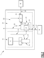
- Figure 1 is a schematic representation of a system 1 or process according to one embodiment of the present invention.
- water is collected from a source 30. Said water is circulated in a fluidic circuit 26. Such water represents a fluid 27 according to the invention and circulates in contact with an electric heating system 24. Downstream said electric heating system 24, said fluid 27 passes through a water treatment system 22, for example a desalination system comprising a reverse osmosis membrane, wherein said fluid 27 is modified as a treated fluid 28 by said water treatment system 22. Downstream said water treatment system 22, the treated fluid 28 is sent to a tank 40 and/or to a recirculation pipe for circulating upstream and/or downstream said electric heating system 24. The fluid 27 coming directly from the source 30 passes through the electric heating system 24 . In an embodiment, said electric heating system 24 is controlled by a controller to regulate the temperature at the input of the water treatment system.
- the PV panel 12 provides electricity 121 to the electric heating system 24.
- the PV panel 12 provides electricity 122 to the water treatment system 22.
- said device 1 comprises at least one pipe 23 to evacuate said fluid 27 downstream said electric heating system 24 and thereby by-passing said electric heating system 24, for example to regulate pressure and temperature of the fluid in contact with the electric heating system 24 and at the input of the water treatment system 22.
- the water treatment unit 20 may also comprise a recirculation pipe 29 downstream the electric heating system 24 and upstream the water treatment system 22, said recirculation pipe 29 feeding the fluidic circuit 26 upstream the electric heating system 24.
- Solar energy is transformed into electricity by the photovoltaic system 12.
- the solar panels of the photovoltaic system 12 are cooled by extracting heat by the cooling system 14. Heat is extracted from the photovoltaic system 12 at the level of the cooling system 14.
- the electric heating system 24 is transferring heat to the fluid 27. Electricity 121 is provided to the electric heating system 24 by the photovoltaic system 12.
- a cooling circuit 16 containing said cooling fluid 17 circulates in the cooling system to extrat heat from the photovoltaic system 12.
- the cooling fluid 17 is physically separate from the fluidic circuit 26 containing said fluid 27.
- this specific configuration of the two fluidic circuits improves the thermal management by separating the function of the fluids.
- the cooling fluid 17 is dedicated to the transfer of heat from the photovoltaic system 12 through the cooling system 14 and the fluid 27 is dedicated to the water treatment system 22.
- the photovoltaic unit 10 comprises one or more materials improving adhesion of the heat exchanger and/or improving heat transfer between the photovoltaic system 12 and the heat exchanger 14
- Circulation pumps allows circulating the fluids properly according to the skilled person knowledge. Control of temperature, pressure, flow rate, quality of the fluids, etc. are also performed according to the skilled person knowledge.
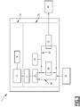
- Figure 3 is a schematic representation of a system 1 or process according to one embodiment of the present invention.
- device 1 comprises a photovoltaic system 12, a water treatment system 22, an electric heating system 24, a pressure exchanger 60, a fluidic circuit 46 for circulating a fluid 47 in contact with said electric heating system 24 and through said water treatment system 22, said photovoltaic system 12 providing electricity to work said electric heating system 24, said device comprising a temperature controller 50 controlling the temperature of the fluid in said fluidic circuit 46, said fluid circulating through said pressure exchanger 60 downstream the water treatment system 22, said pressure exchanger 60 feeding said fluid upstream said water treatment system 22.
- the fluid to be treated by water treatment system 22 may be fed from a water source 30.
- the fluid 46 after water treatment may be sent to a storage tank 40.
- the photovoltaic unit 10 comprises one or more materials improving heat transfer between the photovoltaic system 12 and the heat exchanger 14.
Landscapes
- Life Sciences & Earth Sciences (AREA)
- Engineering & Computer Science (AREA)
- Hydrology & Water Resources (AREA)
- Environmental & Geological Engineering (AREA)
- Water Supply & Treatment (AREA)
- Chemical & Material Sciences (AREA)
- Organic Chemistry (AREA)
- Sustainable Development (AREA)
- Sustainable Energy (AREA)
- Separation Using Semi-Permeable Membranes (AREA)
- Photovoltaic Devices (AREA)
Abstract
The present invention relates to a device (1) comprising a photovoltaic system (12), a water treatment system (22), a cooling system (14), an electric heating system (24), and a fluidic circuit (26) for circulating said fluid (27) in contact with said electric heating system (24) and through said water treatment system (22), said photovoltaic system (12) providing electricity (121) to said electric heating system (24) and said photovoltaic system (12) exchanging heat with said cooling system (14).
The present invention also relates to a process for treating water, wherein said process implements said device (1).
Description
- The present invention concerns a photovoltaic device with thermal management and a method of managing a photovoltaic device with thermal management.
- Water from different sources should be treated for providing water for various uses, including drinkable water. Many devices for treating water are known in the art. One important treatment is water desalination. Desalination plays a pivotal role in the water industry and to mitigate water scarcity.
-
US 2016/0362309 relates to systems and methods wherein hot fluids extracted from the geothermal well may be utilized to generate geothermal energy that can be utilized to power desalination devices to removal minerals and/or salt from produced water from another well. These hot fluids may be recirculated back into the geothermal well to gather heat and to form a closed-looped system that provides thermal energy to the desalination unit. The treated water may be stored for latter agricultural, municipal, and/or other use, or it may be utilized further hydraulic fracturing. -
US 2012/0211409 relates to a photovoltaic-powered reverse osmosis system. The system includes a photovoltaic panel for generating electricity and includes a heat exchanger in thermal contact with the photovoltaic panel. The salt-containing feed water is fed to a reverse osmosis unit to produce clean water therefrom. Fluid circuitry, including a pump, circulates the feed water through the heat exchanger to cool the photovoltaic panel and to heat the feed water. It also delivers the heated feed water to the reverse osmosis unit for desalination. - However, performance of devices of the prior art for treating water can still be improved.
- The present invention aims to solve the technical problem of providing a device and method for treating water having improved efficiency, notably in term of energy saving.
- The present invention also aims to solve the technical problem of providing a device and method for improving electrical energy production efficiency of a solar panel.
- The present invention aims to solve the technical problem of providing a device and method for treating water having improved efficiency, notably in term of energy saving, wherein said device and method also improves electrical energy production efficiency of a solar panel.
- In particular, the present invention aims to solve the technical problem set forth by the present invention in isolated sites, not connected to an electricity grid and not having sufficient energy heat available to work a water treatment system.
- In particular, the present invention aims to solve the technical problem of water desalination, in particular of water desalination in isolated sites, not connected to an electricity grid and not having sufficient energy heat available to work a water treatment system, such as for example in geographical area remote from coastal areas.
- The detailed description is given by reference to the figures for explanatory purposes only, as the invention extends beyond the limited embodiments of the figures. An embodiment, preferred or advantageous feature described, for example in relation to a figure, is combinable with any device or process according to the invention, unless technically impossible.
- The present invention relates to a device 1 comprising a
photovoltaic system 12, awater treatment system 22, acooling system 14, anelectric heating system 24, and afluidic circuit 26 for circulating saidfluid 27 in contact with saidelectric heating system 24 and through said water treatment system 22 (see for examplefigure 1 ), saidphotovoltaic system 12 providingelectricity 121 to saidelectric heating system 24, and saidphotovoltaic system 12 exchanging heat with saidcooling system 14. - Typically, said
photovoltaic system 12 and saidcooling system 14 form aphotovoltaic unit 10 and saidwater treatment system 22, saidelectric heating system 24 and saidfluidic circuit 26 form awater treatment unit 20. - The present invention relates also to a device 1 comprising a
photovoltaic system 12, awater treatment system 22, anelectric heating system 24, apressure exchanger 60, afluidic circuit 46 for circulating afluid 47 in contact with saidelectric heating system 24 and through saidwater treatment system 22, saidelectric heating system 24 being in electric contact with saidphotovoltaic system 12, said device comprising atemperature controller 50 controlling the temperature of the fluid in saidfluidic circuit 46, said fluid circulating through saidpressure exchanger 60 downstream thewater treatment system 22, saidpressure exchanger 60 feeding said fluid upstream said water treatment system 22 (see for examplefigure 3 ). - The present invention relates also to a process for treating water, wherein said process implements a device 1 according to the present invention, comprising a
photovoltaic system 12, awater treatment system 22, acooling system 14, anelectric heating system 24, afluidic circuit 26, , wherein said process comprises circulating afluid 27 in saidfluidic circuit 26, in contact with saidelectric heating system 24 and through saidwater treatment system 22, saidphotovoltaic system 12 providingelectricity 121 to saidelectric heating system 24, and wherein saidphotovoltaic system 12 exchanges heat with saidcooling system 14. - Said
electricity 121 is provided as electrical input to operate saidelectric heating system 24. - Typically, said
electric heating system 24 is in electrical contact with saidphotovoltaic system 12 and in fluidic contact with saidwater treatment system 22.. Typically, thefluidic circuit 26 compriseselectric heating system 24, for example an electrical resistance heating equipment, to transfer heat to thefluid 27 prior to saidwater treatment system 22. - In the prior art, the fluid used to reduce the temperature of photovoltaic systems are collected for heating a defined space (heating in a building) or for production of domestic hot water. Cooling of solar panels by water circulation to recover this water for thermal purposes (central heating or production of domestic hot water) is known. The solar panels are also air-cooled either to ensure the drying of wet material (biomass/wood/etc.) or for domestic heating. Photovoltaic devices are well known but need further improvement in terms of thermal management. Indeed, the skilled person knows that the electric conversion performance of most PV devices, incl. devices based on crystalline silicon, decreases with increasing temperature. There are efforts to decrease the operating temperature of photovoltaic modules.
- The present invention improves the thermal management of solar panels.
- In the present invention, typically said
fluid 27 contains water and are thus aqueous fluids. - In one embodiment, said
fluid 27 is water optionally containing other components. - It has been discovered that a device or method according to the present invention improves the efficiency of said
water treatment system 22 by implementing saidphotovoltaic system 12. - Advantageously, the present invention allows heat (calories) to be removed from said
photovoltaic system 12 in order to improve the efficiency of the water treatment. - Accordingly, the present invention improves at the same time the efficiency of a photovoltaic system and of a water treatment system.
- In one embodiment, heat produced by said
photovoltaic system 12 and collected by a heat exchanger and is transferred to saidwater treatment system 22. - In one embodiment, said
fluid 27 is heated by saidelectric heating system 24 before entering saidwater treatment system 22. - In one embodiment, electrical energy collected from said
photovoltaic system 12 is used in addition for a different purpose than providing only electricity to saidelectric heating system 24. - In one embodiment, electrical energy collected from said
photovoltaic system 12 is used in part for providingelectricity 121 to saidelectric heating system 24 and in part for a different purpose. - Typically, said
photovoltaic system 12 comprises a plurality of solar panels. - Preferably, said
photovoltaic system 12 provideselectric energy 122 to saidwater treatment system 22 as electrical input to operate saidwater treatment system 22. - Advantageously, the electric energy of said
photovoltaic system 12 is used to transfer heat to saidfluid 27. - In one embodiment, said
photovoltaic system 12 provides electric energy to electrically powered devices. - In one embodiment, said
photovoltaic system 12 provideselectric energy 122 to saidwater treatment system 22 andelectric energy 121 to saidelectric heating system 24. - Advantageously, by reducing the temperature of solar panels by way of
saidcooling system 14, the present invention improves electrical energy production efficiency of solar panels. - Advantageously, in an embodiment, increasing the temperature of said
fluid 27 reduces the dynamic viscosity of saidfluid 27. - Advantageously, in an embodiment, increasing the temperature of said
fluid 27 reduces the consumption of electrical energy required to transfer a given quantity offluid 27 through saidwater treatment system 22. - Advantageously, in an embodiment, the lower the solar panel temperature, the better the electrical production efficiency. For example, a solar panel with a temperature coefficient of -0.5%/°C loses 0.5% relative in power output with 1°C increase in temperature for typical operating temperatures.
- Advantageously, increasing the temperature of said
fluid 27 reduces the consumption of energy on thermal water treatment system or method. - Advantageously, increasing the temperature of said
fluid 27 increases the mobility of ions typically contained in saidfluid 27 and improves the transfer through saidwater treatment system 22, for example in particular in case of treatment involving one or more electrodialysis membranes. Indeed, ion mobility increases with temperature thereby improving performance of dialysis of 85% between 25 and 70°C. - In one embodiment, said water treatment comprises a chemical and/or biological reaction in said
water treatment system 22, thereby modifying the composition of saidfluid 27. It is referred to as fluid modification in the present invention. Advantageously, increasing the temperature of saidfluid 27 increases the reaction kinetics of saidfluid 27 when saidfluid 27 is modified by chemical and/or biological reaction. Accordingly, in one embodiment the present invention improves chemical and/or biological reactions by improving reaction kinetics. - Advantageously, the present invention improves the electrical energy production efficiency, the water treatment efficiency and the global process (or method or system) efficiency.
- Advantageously, the water treatment benefits from a temperature increase either by modifying the dynamic viscosity or by modifying the reaction kinetics, in particular in case of a chemical and/or biological oxidation reaction. An example of the modification of the dynamic viscosity: between 25 and 85°C the dynamic viscosity decreases from 0.000891 kg/ms to 0.000334 kg/ms, a decrease of 62.5%.
- In the case of membrane separation, the transmembrane flow depends on the temperature and therefore on the viscosity of the fluid according to the relationship :
JT = JT0 µT/µT0 either by considering the temperatures of 25 and 85°C J85= 0.000891/000334.J25, i.e. J85 = 2.67.J25. - A heat transfer between said
photovoltaic system 12 and saidwater treatment system 22 benefits to both unitary systems (12 and 22) (and to both unitary operations). - Advantageously, the coupling and integrated photovoltaic - water treatment systems and methods according to the present invention offer a better energy efficiency than the installation not benefiting from heat exchange between the photovoltaic and water treatment systems. Advantageously, Operational expenditure (OPEXs) can be expected to decrease through the implementation of heat exchange
- Advantageously, said
electric heating system 24 is used to facilitate the thermal optimization of the system 1. In particular, the present invention allows the electrical energy provided by the cooling of the PV panel to be used for working theelectric heating system 24. Advantageously, the surface temperatures of the photovoltaic panels of thephotovoltaic system 12 and the temperature of the fluid 27 are optimized separately. The preferred parameters to be adjusted or monitored to control the temperature of the photovoltaic panels in thephotvoltaic system 12 and the temperature of thewater treatment system 22 are the heat exchange surface, the materials and design of thecooling system 14, and of theelectric heating system 24, the circulation rate in thecooling circuit 16, the circulation rate in thefluidic circuit 26 and the flow rate of the fluid 27 in contact with said electric heating system 24 (or the circulation rate in the fluidic circuit 26). - An advantage of the present invention is to implement photovoltaic panels that do not require the use of materials that are resistant to corrosion.
- In one embodiment, said
electric heating system 24 is resistant to corrosion. Appropriate material are known by the skilled person. - Advantageously, the present invention limits the influence of intermittency related to solar resources, typically without using battery electricity storage, or by limiting the use of a battery to completely replace photovoltaic panels.
- In one embodiment, said electric heating system (24) is a water heating system.
- Typically, said
electric heating system 24 is selected from the group consisting of immersion heaters, circulation heaters, electrode heaters, induction heaters, etc. - In one embodiment, the electric contact between said
PV system 12 and saidelectric heating system 24 comprises amodulator 21 modulating the electricity provided to saidelectric heating system 24, and thereby advantageously improves the electric heating system by better supporting intermittencies in theelectricity PV system 12.Such modulator 21 is only represented onfigure 3 , but a device or process according tofigure 1 ,2 ,3 or any other embodiment according to the invention may comprise such amodulator 21. - In one embodiment, said
electric heating system 24 comprises a heat storage system. Advantageously, a heat storage system (comprising or not active materials storing heat or a passive heat storage system (like for Domestic Hot Water)) improves the electric heating system by better supporting intermittencies in theelectricity PV system 12. - A device or process according to
figure 1 ,2 ,3 or any other embodiment according to the invention may comprise such a heat storage system. Typically, a heat storage system is in contact with thefluidic circuit 26. - In one embodiment, said device comprises a buffer reservoir in a position to feed said
fluid 27 by gravity flow to saidwater treatment system 22. Advantageously, such buffer reservoir allows the system to run with or without pump and may allow to bring water by gravity flow. - Typically, the
electric heating system 24 is used to heat up the fluid 27 which is fed to thewater treatment system 22. - In one embodiment, said
cooling system 14 comprises or consists of a passive air cooling. - In one embodiment, said
cooling system 14 comprises or consists of a coolingfluid 17 circulating in acooling circuit 16. Typically, in such an embodiment, saidcooling system 14 comprises a heat exchanger with acooling circuit 16 for circulating a coolingfluid 17 through said heat exchanger. - Typically, said
cooling system 14 is selected from the group consisting of plate heat exchanger, solid thermal exchanger, solid phase change material coupled with solid thermal exchanger, flat coil polymeric exchanger etc. - Typically, the
cooling system 14 is a system added to one or more photovoltaic panels. The coolingfluid 17 typically circulates to extract heat and cool down the panel. - In one embodiment, said cooling
fluid 17 and saidfluid 27 are different in their chemical composition. - The present invention has the technical advantage of controlling the quality of the cooling
fluid 17 thereby controlling or optimizing operating conditions of thecooling system 14 and/or theelectric heating system 24. - An advantage of the present invention is also to limit or even eliminate the formation of a biofilm in the cooling
fluid 17. - Typically, the cooling
fluid 17 is selected from the group consisting of a mono- or multi-phases aqueous or non-aqueous fluid, for example water, a gaz, for example air, a coolant, a liquid with one or more phase change materials (PCM), and any mixture of at least two of these components. - In one embodiment, said cooling
fluid 17 comprises or consists of a gas, for example air. - In one embodiment, the cooling
fluid 17 is a coolant. - In one embodiment, said cooling
fluid 17 comprises or consists of one or more heat transfer compound, for example one or more phase change materials (PCM). - In one embodiment, the cooling
circuit 16 comprises one or more phase change materials either suspended in the cooling fluid 17 (and part of the fluid composition) or fixed in thecooling system 14 in contact with said coolingfluid 17 to exchange easily heat with said coolingfluid 17. - In one embodiment, the
fluid circuit 26 comprises one or more phase change materials either suspended in the fluid 27 (and part of the fluid composition) or fixed in a dedicated area of thefluidic circuit 26 in contact with saidfluid 27 to easily exchange heat with saidfluid 27. - By using a phase change material, heat recovery is maximized by recovering the latent heat of fusion from the phase change material chosen to change phase at a temperature below the surface temperature of the photovoltaic panel(s) of the
photovoltaic system 12 and corresponding to the operating temperature of the water treatment system 22 (e. g. 45°C for reverse osmosis). Advantageously, this constant temperature heat recovery is obtained without prejudice to the recovery of the heat corresponding to the temperature difference between the surface temperature of the photovoltaic panel(s) of thephotovoltaic system 12 and the temperature of the cooling fluid, containing the phase change material according to this embodiment. - Advantageously, said cooling
fluid 17 circulates in closed loop in said coolingcircuit 16. - An advantage of a closed loop of said
cooling circuit 16 during operation is to avoid clogging problems with thecooling circuit 16, notably by limiting the formation of deposits in thecooling circuit 16. - In one embodiment, said cooling
fluid 17 exchanges heat withphotovoltaic system 12 through saidcooling system 14. - In one embodiment, said
cooling system 14 reduces the temperature of saidphotovoltaic system 12. - Advantageously, said
fluid 27 exchanges heat with saidelectric heating system 24 before entering saidwater treatment system 22. - Preferably, said
water treatment system 22 improve its performances at higher temperature or require a process step at higher temperature than feed temperature. - Typically, said
water treatment system 22 is a treatment of industrial or domestic water in all aspects of transformation (including for example chemical (oxidation, reduction), physics (ultrasound, precipitation) or separation (membrane techniques, evapo concentrations, evapo crystallization), humidification, dehumidification). - Advantageously, said
water treatment system 22 is implemented where the application benefit from a heat supply, such as for example pump and treat, venting, sparging, in situ oxidation, in situ electrical treatment, such as for example for supplying hot water to an electrode, in situ or ex situ biodegradation, mobilisation by steam sweeping. - In one embodiment, said
water treatment system 22 is selected from the group consisting of a desalination system (microfiltration, ultrafiltration, reverse osmosis, nanofiltration, electrodialysis, distillation/evaporation, humidification-deshumidification, solvent extraction, clathrate based desalination), an oxidation system (ozone, any advanced oxidation processes), a bioreactor, a solid-liquid-liquid separation process (flotator, hydrocyclone, settling tanks, centrifugation), a liquid-liquid separation process, a liquid gas separation process, a thermal treatment such as evaporation, evapo-concentration, humidification-dehumidification, a membrane separation system, a treatment of industrial or domestic water, of natural surface or groundwater including contaminated groundwater, and combination thereof. - Typically, said device comprises one or more controller selected from the group consisting of a controller of the flow rate of the cooling
fluid 17 in thecooling circuit 16, a controller of the flow rate of the fluid 27 in thefluidic circuit 26, a controller of the temperature of the coolingfluid 17 in thecooling circuit 16, a controller of the temperature of thephotovoltaic system 12, a controller of the temperature of the fluid 27 in thefluidic circuit 26. The controllers are not specifically shown on the figures, except thetemperature controller 50 onfigure 3 as an illustrative purpose of an embodiment. - A control system is used to optimize and/or enhance the efficiency and the flux of water treated based on a double loop heat extraction system according to the present invention. The control system is designed to maximize the heat recovery from the panel of the
photovoltaic unit 10 and adjust the required amount of heat to manage thewater treatment unit 20. In an embodiment, the control system allows setting the flow rates and/or the temperatures to the selected values. In an embodiment, the control system adjusts all required parameters for the designedwater treatment unit 20 including pressure ofunit 20. - In an embodiment, the
fluidic circuit 26 includes apurge 25 and a pressure control system. - In an embodiment, the
fluidic circuit 26 comprises atemperature controller 50 controlling the temperature of the fluid in saidfluidic circuit 26. - In an embodiment, the device 1 comprises a
pressure exchanger 60, saidfluid 27 circulating through saidpressure exchanger 60 downstream thewater treatment system 22, saidpressure exchanger 60 feeding said fluid upstream saidwater treatment system 22. Typically the device 1 comprises a pressure controller (not shown in the figures). - One closed loop for heat extraction from the PV panels is represented by said cooling
circuit 16 and one loop for the water treatment is represented by saidfluidic circuit 26. The fluid 27 is fed to saidwater treatment system 22 after temperature increase in contact with saidelectric heating system 24. This control system is designed for thermal management of thephotovoltaic system 12 and the feed influid 27 before thewater treatment system 22, for pressure regulation of thecooling circuit 16, and thefluidic circuit 26, for the optimization of the production and/or efficiency of thephotovoltaic system 12 and of thewater treatment system 22. - In one embodiment, the control system comprises a storage device storing the electrical energy produced by the
photovoltaic system 12 for the optimization or extension of the functioning of saidwater treatment system 22 for example further the sunset or in case of variation to solar exposition of thephotovoltaic system 12. In one embodiment, the energy storage comprises or consists of one or more batteries for storing electricity produced by thephotovoltaic system 12. - In one embodiment, the control system comprises a storage device storing the heat produced by the
photovoltaic system 12 though theheater 14 for the optimization or extension of the functioning of saidwater treatment system 22 for example further the sunset or in case of variation to solar exposition of thephotovoltaic system 12. - In one embodiment, the energy storage comprises or consists of one or more heat storage devices, such as for example coolant, or water tanks or device working with PCM, for storing heat produced by said
water treatment system 22. - In one embodiment, the thermal management comprises one or more devices measuring as input the temperature of one or more solar panels of the
photovoltaic system 12, the temperature of theelectric heating system 24, the temperature of thewater source 30 or the fluid 27 before upstream theelectric heating system 24 and the temperature of the fluid 27 beforewater treatment system 22 and after theelectric heating system 24. - Preferably, the regulation of the thermal management is performed by controlling the speed of the flow through the
closed cooling circuit 16, of the flow through thefluidic circuit 26, in relation with the dimensions of theheat exchanger 14, and in relation with the dimensions of theelectric heating system 24, in order to keep the temperature of the PV panel(s) of thephotovoltaic system 12 at the minimum or optimal temperature, and the temperature at the input of thewater treatment system 22 at a maximum or optimal temperature, respecting constraint of suchwater treatment system 22 such as for example a reverse osmosis system to avoid any degradation thereof. Typically, the speed and the flow of the fluids is controlled by pumps and valves in the fluidic circuits. - A system of valves and purge can be used to regulate the temperature in the
fluidic circuit 26. - In one embodiment, the device 1 comprises a pressure regulation system.
- In one embodiment, the pressure regulation system controls the pressure of the cooling
fluid 17 inside the cooling system 14 (typically on the back of the PV panels) and/or of the fluid 27 in contact with saidelectric heating system 24, within limits defined by the design of thecooling system 14, and/orelectric heating system 24. - In one embodiment, the pressure regulation system monitors the pressure of
fluid 27 feeding thewater treatment system 22, thereby adjusting the flow at the optimal pressure for operating thewater treatment system 22, typically depending on the treatment to perform. - Advantageously the pressure regulation system regulates (or controls) the pressure to compensate intermittency of the solar irradiance of the
photovoltaic system 12. - For example, the pressure regulation system comprises one or more clark pumps or any type of pressure exchanger.
- In one embodiment, said
photovoltaic unit 10 and/or saidwater treatment unit 20 comprise storage tank. Advantageously, one or more storage tanks smooth out the intermittency of photovoltaic system performance and/or the cooling system performance. In such an embodiment, it is possible to extend the optimal heat exchange conditions beyond the moment when the irradiation decreases rapidly and becomes less than optimal for the photovoltaic system. - Typically, said
fluidic circuit 26 is fed by asource 30 of water to be treated, and saidfluid 27 comprises or consists of water to be treated. -
Water source 30 is ground water, produced water, process water, industrial water, drinking water, purified water, deionized water, rain water, domestic water, tap water, river or lake water, waste water, sea water, brackish water, steam condensate, melted ice, contaminated water, etc. - In one embodiment, the treated fluid 28 forms a modified fluid, typically fluid having undergone a chemical and/or biological reaction.
- In one embodiment, the treated fluid 28 forms a clean fluid, typically clean water.
- In one embodiment, said clean or modified fluid is collected and/or stored in a
tank 40. - Accordingly, the device 1 comprises one or more water tank for the collection of (clean) water after its treatment in the
water treatment system 22. - In one embodiment the process of the invention comprises desalinizing water from a
water source 30 by saidwater treatment system 22. - In one embodiment the process of the invention comprises modifying the composition or the quality of a water from a
water source 30 by saidwater treatment system 22. -
Figure 1 is a schematic representation of a system 1 or process according to one embodiment of the present invention. - In an example, water is collected from a
source 30. Said water is circulated in afluidic circuit 26. Such water represents a fluid 27 according to the invention and circulates in contact with anelectric heating system 24. Downstream saidelectric heating system 24, saidfluid 27 passes through awater treatment system 22, for example a desalination system comprising a reverse osmosis membrane, wherein saidfluid 27 is modified as a treatedfluid 28 by saidwater treatment system 22. Downstream saidwater treatment system 22, the treatedfluid 28 is sent to atank 40 and/or to a recirculation pipe for circulating upstream and/or downstream saidelectric heating system 24. The fluid 27 coming directly from thesource 30 passes through theelectric heating system 24 . In an embodiment, saidelectric heating system 24 is controlled by a controller to regulate the temperature at the input of the water treatment system. ThePV panel 12 provideselectricity 121 to theelectric heating system 24. ThePV panel 12 provideselectricity 122 to thewater treatment system 22. - In one embodiment, said device 1 comprises at least one
pipe 23 to evacuate saidfluid 27 downstream saidelectric heating system 24 and thereby by-passing saidelectric heating system 24, for example to regulate pressure and temperature of the fluid in contact with theelectric heating system 24 and at the input of thewater treatment system 22. - The
water treatment unit 20 may also comprise arecirculation pipe 29 downstream theelectric heating system 24 and upstream thewater treatment system 22, saidrecirculation pipe 29 feeding thefluidic circuit 26 upstream theelectric heating system 24. - Solar energy is transformed into electricity by the
photovoltaic system 12. The solar panels of thephotovoltaic system 12 are cooled by extracting heat by thecooling system 14. Heat is extracted from thephotovoltaic system 12 at the level of thecooling system 14. - The
electric heating system 24 is transferring heat to thefluid 27.Electricity 121 is provided to theelectric heating system 24 by thephotovoltaic system 12. - In one embodiment, as illustrated on
Figure 2 , acooling circuit 16 containing said coolingfluid 17 circulates in the cooling system to extrat heat from thephotovoltaic system 12. Advantageously, the coolingfluid 17 is physically separate from thefluidic circuit 26 containing saidfluid 27. Advantageously, according to the invention this specific configuration of the two fluidic circuits improves the thermal management by separating the function of the fluids. The coolingfluid 17 is dedicated to the transfer of heat from thephotovoltaic system 12 through thecooling system 14 and the fluid 27 is dedicated to thewater treatment system 22. In one embodiment, thephotovoltaic unit 10 comprises one or more materials improving adhesion of the heat exchanger and/or improving heat transfer between thephotovoltaic system 12 and theheat exchanger 14 - Circulation pumps allows circulating the fluids properly according to the skilled person knowledge. Control of temperature, pressure, flow rate, quality of the fluids, etc. are also performed according to the skilled person knowledge.
-
Figure 3 is a schematic representation of a system 1 or process according to one embodiment of the present invention. - In
figure 3 , device 1 comprises aphotovoltaic system 12, awater treatment system 22, anelectric heating system 24, apressure exchanger 60, afluidic circuit 46 for circulating a fluid 47 in contact with saidelectric heating system 24 and through saidwater treatment system 22, saidphotovoltaic system 12 providing electricity to work saidelectric heating system 24, said device comprising atemperature controller 50 controlling the temperature of the fluid in saidfluidic circuit 46, said fluid circulating through saidpressure exchanger 60 downstream thewater treatment system 22, saidpressure exchanger 60 feeding said fluid upstream saidwater treatment system 22. The fluid to be treated bywater treatment system 22 may be fed from awater source 30. The fluid 46 after water treatment may be sent to astorage tank 40. In one embodiment, thephotovoltaic unit 10 comprises one or more materials improving heat transfer between thephotovoltaic system 12 and theheat exchanger 14.
Claims (15)
- A device (1) comprising a photovoltaic system (12), a water treatment system (22), a cooling system (14), an electric heating system (24), and a fluidic circuit (26) for circulating said fluid (27) in contact with said electric heating system (24) and through said water treatment system (22), said photovoltaic system (12) providing electricity (121) to said electric heating system (24) and said photovoltaic system (12) exchanging heat with said cooling system (14).
- The device according to claim 1, wherein said fluid (27) exchanges heat with said electric heating system (24) before entering said water treatment system (22).
- The device according to any one of claims 1 to 2, wherein said cooling system (14) comprisses a cooling fluid (17) cooling said photovoltaic system (12) by exchanging heat between said cooling fluid (17) and said photovoltaic system (12).
- The device according to claim 3, wherein said cooling system (14) comprises or consists of a cooling fluid (17) circulating in a cooling circuit (16).
- The device according to any one of claims 1 to 4, wherein said photovoltaic system (12) provides electric energy to said water treatment system (22).
- The device according to any one of claims 1 to 5, wherein said electric heating system (24) is a water heating system.
- The device according to any one of claims 1 to 6, wherein said electric heating system (24) comprises a heat storage system .
- The device according to any one of claims 1 to 7, wherein said device comprises a buffer reservoir in a position to feed said fluid (27) by gravity flow to said water treatment system (22).
- The device according to any one of claims 1 to 8, wherein said cooling system (14) is controlled by a controller to reduce temperature variations of said photovoltaic system (12).
- The device according to any one of claims 1 to 9, wherein said fluidic circuit (26) is fed by a source (30) of water to be treated, and said fluid (27) comprises or consists of water to be treated.
- The device according to any one of claims 1 to 10, wherein said water treatment system (22) is selected from the group consisting of a desalination system, an oxidation system, a bioreactor, a solid-liquid-liquid separation process a liquid-liquid separation process, a liquid gas separation process, a thermal treatment such as evaporation, evapo-concentration, humidification-dehumidification, a membrane separation system, a treatment of industrial or domestic water, of natural surface or groundwater including contaminated groundwater, and combination thereof.
- The device according to any one of claims 1 to 11, wherein said device comprises one or more controller selected from the group consisting of a controller of the flow rate of the cooling fluid (17) in the cooling circuit (16), a controller of the flow rate of the fluid (27) in the fluidic circuit (26), a controller of the temperature of the cooling fluid (17) in the cooling circuit (16), a controller of the temperature of the photovoltaic system (12), a controller of the temperature of the fluid (27) in the fluidic circuit (26).
- A process for treating water, wherein said process implements a device (1) according to any one of claims 1 to 12, comprising a photovoltaic system (12), a water treatment system (22), a cooling system (14), an electric heating system (24), a fluidic circuit (26), wherein said process comprises circulating a fluid (27) in said fluidic circuit (26), in contact with said electric heating system (24) and through said water treatment system (22), said photovoltaic system (12) providing electricity (121) to said electric heating system (24) and wherein said photovoltaic system (12) exchanges heat with said cooling system (14).
- The process according to claim 13, wherein said process comprises desalinizing water from a water source (30) by said water treatment system (22).
- The process according to claim 14, wherein said process comprises modifying the composition or the quality of a water from a water source (30) by said water treatment system (22).
Priority Applications (3)
| Application Number | Priority Date | Filing Date | Title |
|---|---|---|---|
| US17/621,975 US20220242750A1 (en) | 2019-06-25 | 2020-06-25 | Photovoltaic device with thermal management |
| PCT/IB2020/056025 WO2020261175A1 (en) | 2019-06-25 | 2020-06-25 | Photovoltaic device with thermal management |
| EP20744126.2A EP3990392A1 (en) | 2019-06-25 | 2020-06-25 | Photovoltaic device with thermal management |
Applications Claiming Priority (1)
| Application Number | Priority Date | Filing Date | Title |
|---|---|---|---|
| FR2019051563 | 2019-06-25 |
Publications (1)
| Publication Number | Publication Date |
|---|---|
| EP3757070A1 true EP3757070A1 (en) | 2020-12-30 |
Family
ID=68290194
Family Applications (1)
| Application Number | Title | Priority Date | Filing Date |
|---|---|---|---|
| EP19306239.5A Withdrawn EP3757070A1 (en) | 2019-06-25 | 2019-09-30 | Photovoltaic device with thermal management |
Country Status (1)
| Country | Link |
|---|---|
| EP (1) | EP3757070A1 (en) |
Citations (5)
| Publication number | Priority date | Publication date | Assignee | Title |
|---|---|---|---|---|
| US20120211409A1 (en) | 2011-02-23 | 2012-08-23 | Massachusetts Institute Of Technology | Photovoltaic reverse osmosis system with thermal management |
| US20150251923A1 (en) * | 2012-10-02 | 2015-09-10 | Desolenator B.V. | Method and device for treating a fluid |
| US20160268967A1 (en) * | 2013-09-17 | 2016-09-15 | Roger Webb | Modular unit for attachment to solar panel |
| US20160362309A1 (en) | 2015-06-12 | 2016-12-15 | University Of Houston System | Systems and methods for geothermal energy harnessing from wells for water treatment |
| CN107178910B (en) * | 2017-05-22 | 2019-06-11 | 东北电力大学 | A kind of solar energy heat distribution system based on CPVT and step accumulation of heat |
-
2019
- 2019-09-30 EP EP19306239.5A patent/EP3757070A1/en not_active Withdrawn
Patent Citations (5)
| Publication number | Priority date | Publication date | Assignee | Title |
|---|---|---|---|---|
| US20120211409A1 (en) | 2011-02-23 | 2012-08-23 | Massachusetts Institute Of Technology | Photovoltaic reverse osmosis system with thermal management |
| US20150251923A1 (en) * | 2012-10-02 | 2015-09-10 | Desolenator B.V. | Method and device for treating a fluid |
| US20160268967A1 (en) * | 2013-09-17 | 2016-09-15 | Roger Webb | Modular unit for attachment to solar panel |
| US20160362309A1 (en) | 2015-06-12 | 2016-12-15 | University Of Houston System | Systems and methods for geothermal energy harnessing from wells for water treatment |
| CN107178910B (en) * | 2017-05-22 | 2019-06-11 | 东北电力大学 | A kind of solar energy heat distribution system based on CPVT and step accumulation of heat |
Similar Documents
| Publication | Publication Date | Title |
|---|---|---|
| US8323491B2 (en) | Combination of a desalination plant and a salinity gradient power reverse electrodialysis plant and use thereof | |
| KR102274447B1 (en) | Energy self-sufficient system for treating high density salty waste water and side stream using membrane capacitive deionization (mcdi) module, and method for the same | |
| Garg | Renewable energy-powered membrane technology: cost analysis and energy consumption | |
| US20160002073A1 (en) | Renewable desalination of brines | |
| CN108793571B (en) | Enhanced desalination high-salinity wastewater treatment system | |
| JP2013063360A (en) | Seawater desalination plant | |
| CN106186200A (en) | A kind of indirect air cooling unit recuperation of heat and water treatment facilities and method | |
| CN214400132U (en) | System of clean energy sea water desalination coupling salt difference energy power generation facility | |
| KR101338187B1 (en) | Sea to fresh water and binary cycle generation system using solar energy | |
| US20190144308A1 (en) | Systems and Methods for Geothermal Energy Harnessing from Wells for Water Treatment | |
| WO2014091199A1 (en) | Electricity generation using a reverse electrodialysis cell with means agains fouling | |
| Albloushi et al. | Renewable energy-powered membrane systems for water desalination | |
| CN113233680A (en) | Capacitance type membrane distillation seawater desalination device | |
| WO2026060816A1 (en) | Seawater electrolysis hydrogen production system and control method therefor | |
| CN103274546B (en) | Printing and dyeing wastewater pure-turbid separating and waste heat utilizing system | |
| Warkad et al. | Different desalination techniques and it’s economic analysis: a review | |
| US20220242750A1 (en) | Photovoltaic device with thermal management | |
| CN205635216U (en) | Concentrated processing apparatus of desulfurization waste water | |
| KR20110068728A (en) | Energy saving seawater desalination system using heat exchanger and seawater desalination method using the same | |
| JPS60168504A (en) | Salt water desalination method | |
| Tashtoush et al. | Performance analysis and optimization of solar-powered hybrid desalination systems using nitrogen-doped graphene composite phase change materials | |
| CN212292942U (en) | Desulfurization wastewater concentration decrement processing system based on directional driving electrodialysis technology | |
| JPS59154187A (en) | Desalting method utilizing waste heat of diesel engine | |
| CN111573948B (en) | Zero-emission fracturing flow-back fluid treatment system and adjusting method thereof | |
| Eid | Using solar energy technology in sea water desalination in North Sinai according to the Egyptian sustainable development plan 2030 |
Legal Events
| Date | Code | Title | Description |
|---|---|---|---|
| PUAI | Public reference made under article 153(3) epc to a published international application that has entered the european phase |
Free format text: ORIGINAL CODE: 0009012 |
|
| STAA | Information on the status of an ep patent application or granted ep patent |
Free format text: STATUS: THE APPLICATION HAS BEEN PUBLISHED |
|
| AK | Designated contracting states |
Kind code of ref document: A1 Designated state(s): AL AT BE BG CH CY CZ DE DK EE ES FI FR GB GR HR HU IE IS IT LI LT LU LV MC MK MT NL NO PL PT RO RS SE SI SK SM TR |
|
| AX | Request for extension of the european patent |
Extension state: BA ME |
|
| STAA | Information on the status of an ep patent application or granted ep patent |
Free format text: STATUS: THE APPLICATION IS DEEMED TO BE WITHDRAWN |
|
| 18D | Application deemed to be withdrawn |
Effective date: 20210701 |