EP3757018B1 - Systeme und verfahren zur additiven herstellung und reparaturen durch kaltgasspritzen mit gasrückgewinnung - Google Patents
Systeme und verfahren zur additiven herstellung und reparaturen durch kaltgasspritzen mit gasrückgewinnung Download PDFInfo
- Publication number
- EP3757018B1 EP3757018B1 EP20171967.1A EP20171967A EP3757018B1 EP 3757018 B1 EP3757018 B1 EP 3757018B1 EP 20171967 A EP20171967 A EP 20171967A EP 3757018 B1 EP3757018 B1 EP 3757018B1
- Authority
- EP
- European Patent Office
- Prior art keywords
- gas
- nozzle
- gas recovery
- supersonic
- cold spray
- Prior art date
- Legal status (The legal status is an assumption and is not a legal conclusion. Google has not performed a legal analysis and makes no representation as to the accuracy of the status listed.)
- Active
Links
Images




Classifications
-
- B—PERFORMING OPERATIONS; TRANSPORTING
- B05—SPRAYING OR ATOMISING IN GENERAL; APPLYING FLUENT MATERIALS TO SURFACES, IN GENERAL
- B05B—SPRAYING APPARATUS; ATOMISING APPARATUS; NOZZLES
- B05B14/00—Arrangements for collecting, re-using or eliminating excess spraying material
- B05B14/30—Arrangements for collecting, re-using or eliminating excess spraying material comprising enclosures close to, or in contact with, the object to be sprayed and surrounding or confining the discharged spray or jet but not the object to be sprayed
-
- B—PERFORMING OPERATIONS; TRANSPORTING
- B05—SPRAYING OR ATOMISING IN GENERAL; APPLYING FLUENT MATERIALS TO SURFACES, IN GENERAL
- B05D—PROCESSES FOR APPLYING FLUENT MATERIALS TO SURFACES, IN GENERAL
- B05D1/00—Processes for applying liquids or other fluent materials
- B05D1/02—Processes for applying liquids or other fluent materials performed by spraying
- B05D1/025—Processes for applying liquids or other fluent materials performed by spraying using gas close to its critical state
-
- B—PERFORMING OPERATIONS; TRANSPORTING
- B05—SPRAYING OR ATOMISING IN GENERAL; APPLYING FLUENT MATERIALS TO SURFACES, IN GENERAL
- B05D—PROCESSES FOR APPLYING FLUENT MATERIALS TO SURFACES, IN GENERAL
- B05D5/00—Processes for applying liquids or other fluent materials to surfaces to obtain special surface effects, finishes or structures
- B05D5/005—Repairing damaged coatings
-
- B—PERFORMING OPERATIONS; TRANSPORTING
- B22—CASTING; POWDER METALLURGY
- B22F—WORKING METALLIC POWDER; MANUFACTURE OF ARTICLES FROM METALLIC POWDER; MAKING METALLIC POWDER; APPARATUS OR DEVICES SPECIALLY ADAPTED FOR METALLIC POWDER
- B22F10/00—Additive manufacturing of workpieces or articles from metallic powder
- B22F10/20—Direct sintering or melting
- B22F10/25—Direct deposition of metal particles, e.g. direct metal deposition [DMD] or laser engineered net shaping [LENS]
-
- B—PERFORMING OPERATIONS; TRANSPORTING
- B22—CASTING; POWDER METALLURGY
- B22F—WORKING METALLIC POWDER; MANUFACTURE OF ARTICLES FROM METALLIC POWDER; MAKING METALLIC POWDER; APPARATUS OR DEVICES SPECIALLY ADAPTED FOR METALLIC POWDER
- B22F10/00—Additive manufacturing of workpieces or articles from metallic powder
- B22F10/70—Recycling
- B22F10/77—Recycling of gas
-
- B—PERFORMING OPERATIONS; TRANSPORTING
- B22—CASTING; POWDER METALLURGY
- B22F—WORKING METALLIC POWDER; MANUFACTURE OF ARTICLES FROM METALLIC POWDER; MAKING METALLIC POWDER; APPARATUS OR DEVICES SPECIALLY ADAPTED FOR METALLIC POWDER
- B22F12/00—Apparatus or devices specially adapted for additive manufacturing; Auxiliary means for additive manufacturing; Combinations of additive manufacturing apparatus or devices with other processing apparatus or devices
- B22F12/10—Auxiliary heating means
-
- B—PERFORMING OPERATIONS; TRANSPORTING
- B22—CASTING; POWDER METALLURGY
- B22F—WORKING METALLIC POWDER; MANUFACTURE OF ARTICLES FROM METALLIC POWDER; MAKING METALLIC POWDER; APPARATUS OR DEVICES SPECIALLY ADAPTED FOR METALLIC POWDER
- B22F12/00—Apparatus or devices specially adapted for additive manufacturing; Auxiliary means for additive manufacturing; Combinations of additive manufacturing apparatus or devices with other processing apparatus or devices
- B22F12/22—Driving means
-
- B—PERFORMING OPERATIONS; TRANSPORTING
- B22—CASTING; POWDER METALLURGY
- B22F—WORKING METALLIC POWDER; MANUFACTURE OF ARTICLES FROM METALLIC POWDER; MAKING METALLIC POWDER; APPARATUS OR DEVICES SPECIALLY ADAPTED FOR METALLIC POWDER
- B22F12/00—Apparatus or devices specially adapted for additive manufacturing; Auxiliary means for additive manufacturing; Combinations of additive manufacturing apparatus or devices with other processing apparatus or devices
- B22F12/70—Gas flow means
-
- B—PERFORMING OPERATIONS; TRANSPORTING
- B33—ADDITIVE MANUFACTURING TECHNOLOGY
- B33Y—ADDITIVE MANUFACTURING, i.e. MANUFACTURING OF THREE-DIMENSIONAL [3D] OBJECTS BY ADDITIVE DEPOSITION, ADDITIVE AGGLOMERATION OR ADDITIVE LAYERING, e.g. BY 3D PRINTING, STEREOLITHOGRAPHY OR SELECTIVE LASER SINTERING
- B33Y10/00—Processes of additive manufacturing
-
- B—PERFORMING OPERATIONS; TRANSPORTING
- B33—ADDITIVE MANUFACTURING TECHNOLOGY
- B33Y—ADDITIVE MANUFACTURING, i.e. MANUFACTURING OF THREE-DIMENSIONAL [3D] OBJECTS BY ADDITIVE DEPOSITION, ADDITIVE AGGLOMERATION OR ADDITIVE LAYERING, e.g. BY 3D PRINTING, STEREOLITHOGRAPHY OR SELECTIVE LASER SINTERING
- B33Y30/00—Apparatus for additive manufacturing; Details thereof or accessories therefor
-
- B—PERFORMING OPERATIONS; TRANSPORTING
- B64—AIRCRAFT; AVIATION; COSMONAUTICS
- B64F—GROUND OR AIRCRAFT-CARRIER-DECK INSTALLATIONS SPECIALLY ADAPTED FOR USE IN CONNECTION WITH AIRCRAFT; DESIGNING, MANUFACTURING, ASSEMBLING, CLEANING, MAINTAINING OR REPAIRING AIRCRAFT, NOT OTHERWISE PROVIDED FOR; HANDLING, TRANSPORTING, TESTING OR INSPECTING AIRCRAFT COMPONENTS, NOT OTHERWISE PROVIDED FOR
- B64F5/00—Designing, manufacturing, assembling, cleaning, maintaining or repairing aircraft, not otherwise provided for; Handling, transporting, testing or inspecting aircraft components, not otherwise provided for
- B64F5/40—Maintaining or repairing aircraft
-
- C—CHEMISTRY; METALLURGY
- C23—COATING METALLIC MATERIAL; COATING MATERIAL WITH METALLIC MATERIAL; CHEMICAL SURFACE TREATMENT; DIFFUSION TREATMENT OF METALLIC MATERIAL; COATING BY VACUUM EVAPORATION, BY SPUTTERING, BY ION IMPLANTATION OR BY CHEMICAL VAPOUR DEPOSITION, IN GENERAL; INHIBITING CORROSION OF METALLIC MATERIAL OR INCRUSTATION IN GENERAL
- C23C—COATING METALLIC MATERIAL; COATING MATERIAL WITH METALLIC MATERIAL; SURFACE TREATMENT OF METALLIC MATERIAL BY DIFFUSION INTO THE SURFACE, BY CHEMICAL CONVERSION OR SUBSTITUTION; COATING BY VACUUM EVAPORATION, BY SPUTTERING, BY ION IMPLANTATION OR BY CHEMICAL VAPOUR DEPOSITION, IN GENERAL
- C23C24/00—Coating starting from inorganic powder
- C23C24/02—Coating starting from inorganic powder by application of pressure only
- C23C24/04—Impact or kinetic deposition of particles
-
- B—PERFORMING OPERATIONS; TRANSPORTING
- B05—SPRAYING OR ATOMISING IN GENERAL; APPLYING FLUENT MATERIALS TO SURFACES, IN GENERAL
- B05B—SPRAYING APPARATUS; ATOMISING APPARATUS; NOZZLES
- B05B1/00—Nozzles, spray heads or other outlets, with or without auxiliary devices such as valves, heating means
- B05B1/002—Nozzles, spray heads or other outlets, with or without auxiliary devices such as valves, heating means designed to reduce the generation or the transmission of noise or to produce a particular sound; associated with noise monitoring means
-
- B—PERFORMING OPERATIONS; TRANSPORTING
- B05—SPRAYING OR ATOMISING IN GENERAL; APPLYING FLUENT MATERIALS TO SURFACES, IN GENERAL
- B05B—SPRAYING APPARATUS; ATOMISING APPARATUS; NOZZLES
- B05B7/00—Spraying apparatus for discharge of liquids or other fluent materials from two or more sources, e.g. of liquid and air, of powder and gas
- B05B7/14—Spraying apparatus for discharge of liquids or other fluent materials from two or more sources, e.g. of liquid and air, of powder and gas designed for spraying particulate materials
- B05B7/1481—Spray pistols or apparatus for discharging particulate material
- B05B7/1486—Spray pistols or apparatus for discharging particulate material for spraying particulate material in dry state
-
- B—PERFORMING OPERATIONS; TRANSPORTING
- B22—CASTING; POWDER METALLURGY
- B22F—WORKING METALLIC POWDER; MANUFACTURE OF ARTICLES FROM METALLIC POWDER; MAKING METALLIC POWDER; APPARATUS OR DEVICES SPECIALLY ADAPTED FOR METALLIC POWDER
- B22F10/00—Additive manufacturing of workpieces or articles from metallic powder
- B22F10/30—Process control
- B22F10/32—Process control of the atmosphere, e.g. composition or pressure in a building chamber
- B22F10/322—Process control of the atmosphere, e.g. composition or pressure in a building chamber of the gas flow, e.g. rate or direction
-
- B—PERFORMING OPERATIONS; TRANSPORTING
- B22—CASTING; POWDER METALLURGY
- B22F—WORKING METALLIC POWDER; MANUFACTURE OF ARTICLES FROM METALLIC POWDER; MAKING METALLIC POWDER; APPARATUS OR DEVICES SPECIALLY ADAPTED FOR METALLIC POWDER
- B22F12/00—Apparatus or devices specially adapted for additive manufacturing; Auxiliary means for additive manufacturing; Combinations of additive manufacturing apparatus or devices with other processing apparatus or devices
- B22F12/50—Means for feeding of material, e.g. heads
- B22F12/53—Nozzles
-
- B—PERFORMING OPERATIONS; TRANSPORTING
- B22—CASTING; POWDER METALLURGY
- B22F—WORKING METALLIC POWDER; MANUFACTURE OF ARTICLES FROM METALLIC POWDER; MAKING METALLIC POWDER; APPARATUS OR DEVICES SPECIALLY ADAPTED FOR METALLIC POWDER
- B22F2999/00—Aspects linked to processes or compositions used in powder metallurgy
-
- Y—GENERAL TAGGING OF NEW TECHNOLOGICAL DEVELOPMENTS; GENERAL TAGGING OF CROSS-SECTIONAL TECHNOLOGIES SPANNING OVER SEVERAL SECTIONS OF THE IPC; TECHNICAL SUBJECTS COVERED BY FORMER USPC CROSS-REFERENCE ART COLLECTIONS [XRACs] AND DIGESTS
- Y02—TECHNOLOGIES OR APPLICATIONS FOR MITIGATION OR ADAPTATION AGAINST CLIMATE CHANGE
- Y02P—CLIMATE CHANGE MITIGATION TECHNOLOGIES IN THE PRODUCTION OR PROCESSING OF GOODS
- Y02P10/00—Technologies related to metal processing
- Y02P10/25—Process efficiency
-
- Y—GENERAL TAGGING OF NEW TECHNOLOGICAL DEVELOPMENTS; GENERAL TAGGING OF CROSS-SECTIONAL TECHNOLOGIES SPANNING OVER SEVERAL SECTIONS OF THE IPC; TECHNICAL SUBJECTS COVERED BY FORMER USPC CROSS-REFERENCE ART COLLECTIONS [XRACs] AND DIGESTS
- Y02—TECHNOLOGIES OR APPLICATIONS FOR MITIGATION OR ADAPTATION AGAINST CLIMATE CHANGE
- Y02P—CLIMATE CHANGE MITIGATION TECHNOLOGIES IN THE PRODUCTION OR PROCESSING OF GOODS
- Y02P70/00—Climate change mitigation technologies in the production process for final industrial or consumer products
- Y02P70/10—Greenhouse gas [GHG] capture, material saving, heat recovery or other energy efficient measures, e.g. motor control, characterised by manufacturing processes, e.g. for rolling metal or metal working
Definitions
- CCM cold spray additive manufacturing
- Helium is particularly effective.
- Helium supply is finite; Helium is an expensive resource that has been increasing in cost over time.
- CSAM deployment becomes increasingly less viable. Without the ability to reuse Helium from one CSAM repair session to the next, the acquisition cost of fresh Helium typically represents the bulk of total repair costs.
- US 5 795 626 A in accordance with its abstract, states an environmentally compliant triboelectric applicator and process for coating or ablating a substrate and for retrieving excess or ejected material from the substrate.
- the applicator comprises an inner supersonic nozzle for accelerating triboelectrically charged projectile particles entrained in a supersonic gas to speeds sufficiently high to coat or ablate a substrate and an outer evacuator nozzle coaxially surrounding the inner supersonic nozzle for retrieving excess projectile particles, ablated substrate powders, or other environmentally hazardous materials.
- a fluid dynamic coupling uses the efficacy of the Mach turning angle associated with a supersonic boundary layer of carrier gas to aspirate the central core of the supersonic two-phase jet. This fluid coupling and spacing between the outlet of the supersonic nozzle and the substrate also permits the projectile particles and substrate to triboelectrically charge to levels which induce electrostatic discharges at the substrate simultaneous to the impacts.
- a cold spray system in accordance with its abstract, states that a cold spray system includes a spray nozzle for depositing material onto a substrate.
- a collection assembly at least partially surrounds the spray nozzle for vacuuming undeposited material and gases in the work area.
- the collection assembly includes a transparent collection tube at an end portion of the collection assembly to provide visibility to the work area.
- the collection assembly includes a shield having a flange that extends radially outwardly from the collection assembly and is generally parallel to a substrate. An angled portion of the shield extends from the collection assembly. A radius portion adjoins the flange and the angled portion. A ring is spaced between the spray nozzle and the shield.
- An inner surface of the ring deflects material that typically would otherwise not become adhered to the substrate back into the collection assembly to minimize the material that must be vacuumed at the substrate.
- a curved surface of the ring extends from a surface spaced from the substrate toward the shield to provide a smooth transition for materials flowing along the substrate back into the collection assembly.
- WO 2017/223236 A1 in accordance with its abstract, states limitations with methods, systems and processes for integrating multiple advanced technologies into a single automated manufacturing and repair cell.
- the methods, systems and processes of WO' 236 A1 leverage unique software and hardware to configure a manufacturing cell that is capable of conducting process development and planning, dimensional analysis, pre-machining, surface preparation, cold spray (supersonic particle deposition), dust collection, helium recovery, and post machining in a single integrated manufacturing and repair cell.
- a gas recovery nozzle and a method for performing cold spray additive manufacturing as defined in the independent claims are provided. Further embodiments of the claimed invention are defined in the dependent claims. Although the claimed invention is only defined by the claims, the below embodiments, examples, and aspects are present for aiding in understanding the background and advantages of the claimed invention.
- Cold spray additive manufacturing is a material-deposition process where metal or metal-ceramic mixtures of powders (also referred to as “particles” herein) suspended in a gas propelled at supersonic speed are used to form a coating or freestanding structure.
- cold spraying is defined herein as spraying a material at a temperature that is below the melting point of the material being sprayed.
- CSAM is a solid state process: neither the powders nor the substrate to which the powders are applied are melted during the process.
- use of CSAM provides material-deposition that does not cause thermally induced alterations to the substrate or powder (e.g., deformation, crystallization, imperfections, or other types of damage). Due to the direct impingement of the gases carrying the powders upon the substrate, cold spray generates a stationary shock wave and also a lateral flow of gas along the surface of the part subject to CSAM.
- a stationary shock wave in the context of the flow of supersonic gas is a discontinuity that forms in order for the flow to meet some downstream condition (e.g., an obstacle or back pressure).
- some downstream condition e.g., an obstacle or back pressure.
- the back pressure becomes too great, the flow of gas cannot achieve supersonic speeds and is compressed at the nozzle before expanding.
- the presence of stationary shock waves thus detracts from optimal supersonic gas flow in CSAM systems and methods. Implementations of the disclosure also mitigate such stationary shock waves.
- High- and low-pressure cold spray is an emerging technology finding increasing applications in various types of structural repairs.
- cold spray is usable to repair metallic structures (e.g., airplane or helicopter components).
- a closer examination of an implantation of a CSAM apparatus and process is provided in the discussion of FIG. 5 herein.
- implementations of the disclosure include systems and methods for cold spray additive manufacturing with gas recovery that provide a superior cost/benefit ratio in comparison to conventional cold spray implementations.
- Recapturing and reusing the gas enables potentially large cost savings and renders cold spray additive manufacturing far more commercially viable and efficient.
- the various implementations not only allow for the reuse of the gas, but also enable cold spray additive manufacturing to occur in situ in an open environment (e.g., repairs on an airplane in an airplane hangar). Because no cold spray booth is required, the implementations completely avoid the need for disassembly, shipping a damaged part to a repair facility, conducting repairs in a booth fitted with a gas recovery system, shipping back to the point of origin, and reassembly. Comparatively, conducting cold spray additive manufacturing -based repairs in situ in an open environment is efficient, far less expensive, and avoids entirely multiple vectors for new damage to parts involved in contemporary pre-existing cold spray processes as well as the associated follow-up costly repairs or replacements.
- the elements described herein in various implementations operate in an unconventional manner to provide systems and methods for cold spray additive manufacturing with gas recovery by utilizing a gas recovery nozzle.
- Implementations of the gas recovery nozzle are configured to attach to a supersonic nozzle used to conduct cold spray additive manufacturing.
- the gas recovery nozzle captures a lateral flow of gas from a part under repair and circulates the gas to a gas recovery sub-system.
- the gas recovery nozzle accomplishes this by creating an envelope over the supersonic nozzle that captures at least some of the gas that is deflected laterally on impact with the part under repair during cold spray additive manufacturing.
- the captured gas is circulated to the gas recovery sub-system.
- the gas recovery sub-system collects the captured gas into storage devices for later treatment (e.g., purification) and reuse in future cold spray additive manufacturing processes.
- Some implementations of the gas recovery nozzle further comprise a flexible coupling to control the standout distance from the gas recovery nozzle to the substrate of the part. Maintaining an efficient standout distance between the gas recovery nozzle and the substrate of the part: (1) prevents additive particles from clogging either the supersonic nozzle or the gas recovery nozzle, allowing for a higher sustained rate of gas recovery per unit time; (2) prevents a stationary shock wave of the gas recovery nozzle from interfering with a supersonic flow of gas; (3) focuses or redirects the supersonic flow of gas in a useful and beneficial way; and (4) provides an adequate sealing that increases the gas capture rate. Effects of various standout distances on various implementations of the disclosure are discussed elsewhere herein.
- the gas recovery nozzle acts as a suppressor for the supersonic nozzle, significantly reducing the very high decibel noise, and the associated disruption (e.g., from hearing damage or an inability to hear shouted warnings in a work area), typical of cold spray additive manufacturing solutions.
- the flexible coupling is a single component; in other implementations the flexible coupling is a mechanism with more than one component. Multi-part flexible couplings include but are not limited to flexible couplings assembled using petal joins.
- implementations of the present disclosure are thus superior to typical implementations of cold spray additive manufacturing systems and methods that fail completely to capture and reuse gas when repairs are conducted in situ without disassembly and use of a repair booth.
- the disclosure is thus mechanically more robust and more cost effective to implement, while at the same time being more effective than conventional systems and methods for cold spray additive manufacturing at both enabling reuse of supersonically-propelled gas and in-situ repairs.
- a cross-sectional side elevation view illustrates an implementation of a gas recovery nozzle 100 in accordance with an implementation.
- the gas recovery nozzle 100 comprises a main body 102 configured to attach to a supersonic nozzle 180 and a first end 104 having angled walls 106 at an opening 108 defining a gas flow path 110 from the supersonic nozzle 180.
- a larger diameter opening is thereby defined at the distal end by an angled wall portion between laterally or longitudinally (e.g., straight) extending wall portions extending outward from a distal end of the supersonic nozzle.
- the first end 104 can take different shapes and configurations, such as having curved or arcuate walls that are continuously or gradually increasing or decreasing in curvature. That is, the present disclosure contemplates different conical shaped ends, or ends having different angled openings.
- first end 104 is illustrated as being located within the main body 102. However, the first end 104 in some implementations extends to the end of the main body 102. In various implementations the first end 104 is co-axial with the main body 102.
- the gas recovery nozzle 100 further comprises a passage 112 extending from the first end 104 to a second end 114.
- the first end 104 is a distal end and the second end 114 is a proximal end relative to the supersonic nozzle 180.
- the gas recovery nozzle 100 further comprises a cavity 116 surrounding the passage 112.
- the cavity 116 is configured to collect at least some gas 160 expelled from the supersonic nozzle 180.
- an open end 140 of the cavity 116 at a part side 142 comprises curved walls 144 (e.g., arcuate shaped).
- the open end 140 of the cavity 116 extends farther distally than the opening 108 at the first end 104 (and has a greater diameter than the first end 104 such that a space is defined between a gas flow path having the opening 108, and an inner surface of the main body 102). That is, the conical shaped first end 104 is positioned concentrically within the main body 102 and does not extend to the open end 140.
- the curved wall 144 is shaped and/or configured to facilitate capture of the expelled gas 160 after impinging on a part 152.
- the gas 160 comprises an at least one of Helium or Nitrogen gas.
- Helium is the preferred gas 160.
- the speed of the gas 160 correlates with the speed of sound and the Mach number of the gas 160.
- the speed of sound at standard atmospheric conditions is 1007 m/s (1620 k/s).
- the speed of sound at standard atmospheric conditions is only 349 m/s (561 k/s). This translates into higher particle velocities when Helium is used versus when Nitrogen is used.
- cost and availability that is, if the disclosure herein is implemented such that the gas 160 is reusable across cold spray sessions), then Helium provides superior performance in CSAM applications versus Nitrogen.
- the cavity 116 defines a gas recovery path 162 that leads to an outlet 118. That is, the gas recovery nozzle 100 further comprises the outlet 118 within the main body 102 configured to connect to a gas recovery sub-system 190. In some implementations, the outlet 118 comprises an opening 120 configured to connect to a compressor pump 192 of the gas recovery sub-system 190. In some implementations including the compressor pump 192, a gas diffuser 196 is provided at the opening 120 of the cavity 116, which can be located inside, outside, or both inside and outside the cavity 116.
- the gas diffuser is constructed of an open pore metallic foam (e.g., ALUPOR TM cast aluminum metallic foam) or any mechanically equivalent material or component (e.g., a RADNOR ® 14 Series gas diffuser).
- the gas diffuser 196 is configured to slow the flow of the gas 160 inside the cavity 116 to the opening 120.
- the gas diffuser 196 facilitates at least one of slowing the flow of gas 160 or directing the flow of gas 160 to the compressor
- the outlet 118 comprises an opening 120 configured to connect to a movable gas recovery tank 194.
- more than one moveable gas recovery tank 194 is connected to the opening 120.
- the compressor pump 192, other suitable type of pump, the turbofan, vacuum, or any other mechanically suitable mechanism configured to both intake the gas 160 into the gas recovery sub-system 190 is further configured to ensure that the greatest possible volume of the gas 160 is compressed into and stored in the moveable gas recovery tank 194.
- purification includes removal of Oxygen and other matter that is not the gas 160.
- the main body 102 is tubular and configured to surround an end 182 of the supersonic nozzle 180 (not illustrated).
- the main body 102 is configured as a removable cover 130 to capture a flow of gas 160 from the supersonic nozzle 180 and circulate the gas 160 to the gas recovery sub-system 190. That is, the main body 102 is removably coupled to the supersonic nozzle 180, which may include mechanical attachment (e.g., bolt or screw attachment to a portion of the base of the supersonic nozzle 180) to secure the main body 102 thereto. That is, in some implementations, the gas recovery nozzle 100 is fixed proximate to the supersonic nozzle 180 by at least one screw or other mechanically suitable fastener.
- the gas recovery nozzle 100 further comprise a flexible coupling 150 attached to the first end 104 and configured to engage the part 152.
- the part 152 is any item (e.g., portion of an aircraft or helicopter) requiring CSAM repair processes.
- the flexible coupling 150 is ring-shaped and positioned proximate to the substrate of the part 152 and forms at least a partial seal between the gas recovery nozzle 100 and the part 152.
- the flexible coupling 150 comprises a gas capture cover 154.
- the flexible coupling 150 is constructed of at least one of an elastomer, flexible metallic material, or other mechanically suitable material that is sufficiently durable to provide an acceptable service lifetime before needing replacement, and also able to conform to the contours and dimensions of variously shaped parts 152.
- the flexible coupling 150 which is configured as a gas capture cover 154 in the illustrated implementation, addresses the standout distance effect, which has considerable performance implications for any implementation of CSAM in general and the gas recovery nozzle 100 in particular. If the standout distance between the gas recovery nozzle 100 and the part 152 is too small, the gas recovery nozzle 100 will be subject to clogging and other phenomenon having a deleterious performance impact and eventually requiring cleaning or even replacement.
- the flexible coupling 150 addresses the standout distance effect by (1) providing superior control of the exact standout distance during any CSAM repair session versus implementations not using the flexible coupling 150, and (2) in some implementations, directly contacting or almost contacting the substrate of the part 152 to further reduce the amount of used gas able to escape recapture.
- the flexible coupling 150 further comprises a spring or mechanical or electrical actuator to maintain such contact or partial contact.
- the flexible coupling 150 is a single component; in other implementations the flexible coupling 150 is a mechanism with more than one component. Multi-part flexible couplings 150 include but are not limited to flexible couplings 150 assembled using petal joins.
- FIG. 1 illustrates the gas recovery nozzle 100 comprising the flexible coupling 150 configured to mitigate the standout distance effect described above.
- FIG. 5 as discussed elsewhere herein illustrates an implementation of a gas recovery nozzle not including the flexible coupling 150, demonstrating that implementations of the disclosure are still functional even when a flexible coupling or gas capture cover is not present to mitigate the standout distance effect.
- the gas recovery nozzle 100 further comprise a heat transfer device 170 proximate to the supersonic nozzle 180 and the main body 102.
- the heat transfer device 170 is configured to regulate a temperature of the gas 160 such that the gas recovery nozzle 100 is protected from heat-induced damage from a flow of the gas 160.
- the heat transfer device 170 further comprises a liquid cooling system.
- the heat transfer device 170 is any suitable device for transferring waste heat.
- the heat transfer device 170 is at least one of a heat pipe, heat sink, liquid cooling tube, or any other suitable heat transfer device or mechanism that is capable of transferring waste heat away from the gas 160 and or the gas recovery nozzle 100.
- the gas expansion will reduce the temperature of the gas proximate to the first end 104, cooling is more relevant close to the second end 114.
- the heat transfer device 170 is an open system, such as a liquid cooling tube wherein the fluid flowing through the liquid cooling tube is in thermal communication with one or more additional heat transfer devices, such as a heat sink such that heat may be transferred from the heat transfer device 170 to the heat sink.
- a heat sink can be cooled with air, liquid, or a fan, or the heat sink can be a cold plate, or any other suitable heat sink.
- waste heat carried by the heat transfer device 170 is dissipated into space using protrusions in thermal communication with the heat transfer device 170.
- the heat transfer device 170 is a closed system (e.g., a pulsating heat pipe (“PHP”) or loop heat pipe (“LHP”)).
- PPP pulsating heat pipe
- LHP loop heat pipe
- Each of the PHP and LHP are passive devices that operate under pressure differences caused by heat to force heated fluid to propagate toward a heat sink or other location where waste heat is withdrawn from the fluid.
- the heat transfer device 170 utilizes various configurations of heat pipes, such as straight, curved, crossing, or any number of configurations for achieving a desired amount of cooling.
- the heat transfer device 170 is configuration in various implementations to surround at least a portion of the main body 102 and be positioned between the main body 102 and the supersonic nozzle 180.
- FIG. 2 is a side elevation illustration of a spray path of an implementation of a cold spray additive manufacturing system 200 in use in accordance with an implementation.
- the cold spray additive manufacturing system 200 does not show a gas recovery nozzle (e.g., the gas recovery nozzle 100 of FIG. 1 ), but instead illustrates how gas 208 (e.g., the gas 160 of FIG. 1 ) is lost when the gas recovery nozzle is not present.
- a nozzle 202 e.g., the supersonic nozzle 180 of FIG. 1 ) propels additive particles 204 along the additive vector 210 to a substrate 206 through the nozzle 202 at a supersonic speed using the gas 208 to perform cold spray additive manufacturing of a part 212.
- the used gas escapes laterally along the substrate of the part 212, on the escape vector 220. Without use of the gas recovery nozzle as disclosed elsewhere herein, all of the gas 208 is lost along the escape vector 220 and cannot be reused. In some implementations, there are multiple escape vectors 220, each with a different direction. Gas traversing along any of the escape vectors 220 is permanently lost.
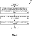
- FIG. 3 is a flowchart illustrating a method 300 for performing cold spray additive manufacturing of a part (e.g., the part 152) in accordance with an implementation.
- the process shown in FIG. 3 is performed by, at least in part, a gas recovery nozzle, a supersonic nozzle, a heat transfer device, and a gas recovery sub-system, such as the gas recovery nozzle 100, the supersonic nozzle 180, the heat transfer device 170, and the gas recovery sub-system 190 in FIG. 1 .
- the method 300 propels particles to a substrate through a nozzle at a supersonic speed using a gas to perform cold spray additive manufacturing of a part at operation 302, captures a flow of the gas propelled from an end of the nozzle at operation 304, and circulates the flow of the gas to a gas recovery system at operation 306.
- the method 300 allows for in-situ cold spray additive manufacturing of a part.
- the substrate comprises at least one of the original substrate of a part or material (e.g., particles) applied previously to the original substrate (e.g., via a previous application of a CSAM method).
- a cloud service performs one or more of the operations (e.g., by controlling the nozzle to cause particles to be propelled to a substrate through a nozzle at a supersonic speed using a gas to perform cold spray additive manufacturing of a part).
- the propelling of particles comprises structurally repairing the part in situ as further described elsewhere in this disclosure.
- the gas comprises an at least one of a high-pressure Helium or Nitrogen gas.
- the gas comprises an at least one of a low-pressure Helium or Nitrogen gas.
- FIG. 4 is a flow chart illustrating another method 400 for performing cold spray additive manufacturing of a part (e.g., the part 152) in accordance with an implementation.
- the method shown in FIG. 4 is performed by, at least in part, a gas recovery nozzle, a supersonic nozzle, a heat transfer device, a gas recovery sub-system, a flexible coupling, and a gas capture cover, such as the gas recovery nozzle 100, the supersonic nozzle 180, the heat transfer device 170, the gas recovery sub-system 190, the flexible coupling 150, and the gas capture cover 154 in FIG. 1 .
- the method 400 uses a flexible coupling attached to an end of the nozzle to seal a gas capture cover, coupled to the nozzle, to the part at operation 402.
- Operations 404, 406, and 408 are similar to operations 302, 304, and 306 of the method 300 depicted in FIG. 3 , and accordingly the description will not be repeated.
- the method 400 accommodates for variations in standout distances as described in more detail herein.
- a cloud service performs one or more of the operations (e.g., by controlling the nozzle to cause particles to be propelled to a substrate through a nozzle at a supersonic speed using a gas to perform cold spray additive manufacturing of a part).
- FIG. 5 An operating environment is illustrated in FIG. 5 showing a block diagram of an implementation of a system 500 for performing cold spray additive manufacturing with gas recovery in accordance with an implementation.
- the system 500 comprises a robotic control system 502 configured to control a cold spray apparatus 504.
- the robotic control system further comprises a robotic positioning arm 516 (e.g., robotically controlled mechanical arm).
- the robotic control system 502 is a manual or at least partially automated apparatus.
- the robotic control system is controllable using a computing device, such as the computing device 800 of FIG. 8 herein.
- the robotic positioning arm 516 is at least a five-axis positioning system that includes two axes for positioning in a plane of the part under repair, one axis for the standout distance, and two additional axes for additional requisite positioning.
- the robotic positioning arm 516 is at least a two axis positioning system for XY positioning in the plane of part under repair and a rolling system that maintains parallelism and standout distance with the substrate of the part under repair.
- the robotic positioning arm 516 in some implementations, is an ADEPT ® Viper robot from Omron Adept Technologies, Inc.
- the cold spray apparatus 504 of the system 500 further comprises a supersonic nozzle 535 (e.g., implemented as the supersonic nozzle 180 of FIG. 1 ) and is configured to perform cold spray additive manufacturing of a part 506 (e.g., the part 152 of FIG. 1 ).
- the cold spray apparatus 504 is further configured to cold spray a powder 530 onto a substrate 551 of the part 506.
- the cold spray apparatus 504 further comprises a source 518 of gas 512 connected to a gas control module 520.
- the gas control module 520 controls the flow of the gas 512 through a first line 515 connected to the supersonic nozzle 535 and through a second line 520 connected to a powder chamber 531 and then to the supersonic nozzle 535.
- the cold spray apparatus 504 additionally comprises a heater 525 that heats the gas 512 to a requisite temperature prior to entrance of the gas 512 into the supersonic nozzle 535.
- the substrate 551 is also heated to further facilitate mechanical bonding.
- the gas 512 flows through the first line 515 and the second line 520 causing the powder 530 located within the powder chamber 531 to be sprayed in a supersonic gas jet from the supersonic nozzle 535 as a particle stream 540.
- the particle stream 540 is sprayed at a temperature below the melting point of the powder 530 and travels at a supersonic velocity from the supersonic nozzle 535.
- the particle stream 540 travels at several times the speed of sound. (The exact speed of sound at a given time varies depending on local conditions). In some implementations, the particle stream 540 travels at least two- to four-times the speed of sound.
- the particle stream is deposited on the substrate 551 of the part 506, whereby on impact on the substrate 551, particles of the particle stream 540 undergo plastic deformation due to the supersonic velocity of the particle stream 540 and bond to each other and the substrate 551 of the part 506 using mechanical energy.
- the heater 525 accelerates the speed of the particle stream 540, but the heat from the heated gas 512 is not transferred to the bonding of the particles of the particle stream 540. Thus, the heat cannot cause deformities, warping, stresses, or other deleterious impacts to the bonding.
- the substrate 551 is further processes, such as polished to create or restore a smooth finish.
- the system 500 further comprises a gas recovery nozzle 508 (e.g., implemented as the gas recovery nozzle 100 of FIG. 1 ).
- the gas recovery nozzle 508 comprises a main body (e.g., implemented as the main body 102 of FIG. 1 ) configured to attach to the supersonic nozzle; a first end (e.g., implemented as the first end 104 of FIG. 1 ) having angled walls (e.g., implemented as the angled walls 106 of FIG. 1 ) at an opening (e.g., implemented as the opening 108 of FIG. 1 ) defining a gas flow path (e.g., implemented as the gas flow path 110 of FIG.
- a gas flow path e.g., implemented as the gas flow path 110 of FIG.
- a passage e.g., implemented as the passage 112 of FIG. 1
- a second end e.g., implemented as the second end 114 of FIG. 1
- the first end being a distal end and the second end being a proximal end relative to the supersonic nozzle.
- the gas recovery nozzle 508 further comprises a cavity (e.g., implemented as the cavity 116 of FIG. 1 ) surrounding the passage and configured to collect at least some gas 512 (e.g., such as the gas 160 of FIG. 1 ) expelled from the supersonic nozzle and defining a gas recovery path (e.g., implemented as the gas recovery path 162 of FIG. 1 ), and an outlet (e.g., implemented as the outlet 118 of FIG. 1 ) within the main body configured to connect to a gas recovery sub-system 510 (e.g., implemented the gas recovery sub-system 190 of FIG. 1 ).
- a cavity e.g., implemented as the cavity 116 of FIG. 1
- gas recovery path e.g., implemented as the gas recovery path 162 of FIG. 1
- an outlet e.g., implemented as the outlet 118 of FIG. 1
- a gas recovery sub-system 510 e.g., implemented the gas recovery sub-system 190 of FIG. 1 .
- the gas recovery sub-system 510 is configured to connect to the outlet and also configured to collect at least some gas 512 expelled from the supersonic nozzle 535 through the gas recovery path into a storage device 514 (e.g., implemented as the moveable gas recovery tank 194 of FIG. 1 ). The gas 512 is thereby collected into the storage device 514 and is stored for treatment and reuse in the cold spray apparatus 504.
- a storage device 514 e.g., implemented as the moveable gas recovery tank 194 of FIG. 1 .
- the gas recovery sub-system 510 further comprises a gas condenser 560 configured to condense at least some gas 512 in the storage device 514, such that storage device 514 stores the greatest possible volume of at least some gas 512.
- the gas condenser 560 is the compressor pump 192 of FIG. 1 or an equivalent device.
- the storage device 514 is configured to be transportable to a purifier configured to remove all contaminants from at least some gas 512 such that at least some gas 512 is suitable for re-use in the cold spray apparatus 504.
- Non-Structural Cold Spray is concerned with adding thickness to a part. This technology has been developed and matured to the point that the United States Department of Defense has installed Non-Structural Cold Spray repair systems at many depots. Non-structural cold spray does not require the use of Helium carrier gas, due to less demanding mechanical requirements.
- Various implementations of the disclosure herein are targeted to Structural Cold Spray, which is concerned not merely with adding thickness to existing parts but reconditioning and repair of damaged, worn, or otherwise out of spec parts.
- Structural Cold Spray is suitable to repair corrosion, repair cracks, or restore tolerances/exact dimensions. Additionally, some implementations of Structural Cold Spray do not require stripping and reapply the finish of the part subject to repair.
- CSAM mechanically bonds particles to a substrate using purely mechanical energy, with no need for added adhesives.
- the implementations herein provide apparatuses, methods, and systems for using cold spray technology to conduct structural repairs in situ by capturing the flow of gas from the supersonic nozzle during a cold spray process and circulating the gas to a gas recovery sub-system for later reuse in additional cold spray processes.
- Some implementations of the gas recovery nozzle incorporate a cover (e.g., a flexible coupling) to capture the flow of gas and circulate the gas to the gas recovery sub-system.
- the disclosure herein operates at the point of repair to capture spent gas proximate to a supersonic nozzle via a gas recovery nozzle and store the gas for later purification and reuse.
- any implementation described herein as being incorporated into or being used in combination with a specific type of vehicle e.g., an aircraft or helicopter
- a specific type of vehicle e.g., an aircraft or helicopter
- any other type of vehicle e.g., trains, submersibles, tanks, armored personnel carriers, watercraft, etc.
- Implementations of the disclosure herein are well-suited to repairing aircraft in-situ as described elsewhere herein, allowing the service life of such aircraft to be maximally extended at lesser cost.
- Cold spray is recognized by various organizations as a solution distinct from and advantageous over thermal spray.
- MIL-STD-3021 DOD Manufacturing Process Standard, Materials Deposition, Cold Spray
- the cost of each cold spray additive manufacturing repair session can include at least $1,000-$2,000 per hour in unrecoverable, single-use Helium expenditures. In many instances, this comprises the majority of the expense for such cold spray additive manufacturing repair sessions. Such sessions take more time and cost more money the more complex the part is that is under repair. Without a means to reuse the Helium, the commercial economic viability of CSAM repair is severely curtailed.
- a gas recovery sub-system e.g., the gas recovery sub-system 190 of FIG. 1 or 510 of FIG. 5
- the disclosure is usable with a number of commercially available purification/purifier systems, including those both presently available and not yet released.
- the disclosure is usable with QUANTUMPURE CS TM and QuantumPure CS-TRI GAS TM Helium recovery and purification systems by Quantum Technology Corporation.
- the operations illustrated in FIG. 3 and FIG. 4 are performed by a single person, a group of persons, a fully- or partially-automated cold spray additive manufacturing with gas recovery system, or any combination of the foregoing.
- the gas recovery nozzle, supersonic nozzle, heat transfer device, and gas recovery sub-system are each be provided by distinct suppliers to a wholly separate assembler who couples the gas recovery nozzle to the supersonic nozzle.
- the present disclosure is operable within an aircraft manufacturing and service method according to an implementation as a method 600 in FIG. 6 .
- some implementations of method 600 include specification and design of the aircraft at operation 602, and material procurement at operation 604.
- some implementations of method 600 include component and subassembly manufacturing at operation 606 and aircraft system integration at operation 608.
- the aircraft undergoes certification and delivery at operation 610 in order to be placed in service at operation 612. While in service of a customer, the aircraft is scheduled for routine maintenance and service at operation 614.
- operation 614 comprises modification, reconfiguration, refurbishment, and other operations associated with maintaining the aircraft in acceptable, safe condition during ongoing flight operations. Systems and methods for cold spray additive manufacturing as disclosed herein are used during operation 614.
- a system integrator comprises any number of aircraft manufacturers and major-system subcontractors
- a third party comprises any number of vendors, subcontractors, and suppliers
- an operator comprises an airline, leasing company, military entity, service organization, and similar entities providing similar sales and leasing services.
- the present disclosure is operable in a variety of terrestrial and extra-terrestrial environments for a variety of applications.
- the following exemplary operating environment is presented.
- the present disclosure is operable within an aircraft operating environment according to an implementation as an aircraft 700 in FIG. 7 .
- Implementations of the aircraft 700 include but are not limited to an airframe 702, a plurality of high-level systems 704, and an interior 706.
- Some implementations of the aircraft 700 incorporate high-level systems 704 including but not limited to: one or more of a propulsion system 708, an electrical system 710, a hydraulic system 712, and an environmental system 714. Any number of other systems may be included in implementations of the aircraft 700.
- an aerospace implementation is shown, the principles are applicable to other industries, such as the automotive and nautical industries.
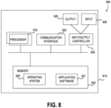
- the present disclosure is operable with a computing apparatus according to an implementation as a functional block diagram 800 in FIG. 8 .
- components of a computing apparatus 818 may be implemented as a part of an electronic device according to one or more implementations described in this specification.
- the computing apparatus 818 comprises one or more processors 819 which may be microprocessors, controllers or any other suitable type of processors for processing computer executable instructions to control the operation of the electronic device.
- Platform software comprising an operating system 820 or any other suitable platform software may be provided on the apparatus 818 to enable application software 821 to be executed on the device.
- the cold spray additive manufacturing system as described herein may be implemented at least partially by software.
- Computer executable instructions may be provided using any computer-readable media that are accessible by the computing apparatus 818.
- Computer-readable media may include, without limitation, computer storage media such as a memory 822 and communications media.
- Computer storage media, such as a memory 822 include volatile and non-volatile, removable and non-removable media implemented in any method or technology for storage of information such as computer readable instructions, data structures, program modules or the like.
- Computer storage media include, but are not limited to, RAM, ROM, EPROM, EEPROM, flash memory or other memory technology, CD-ROM, digital versatile disks (DVD) or other optical storage, magnetic cassettes, magnetic tape, magnetic disk storage or other magnetic storage devices, or any other non-transmission medium that is usable to store information for access by a computing apparatus.
- communication media may embody computer readable instructions, data structures, program modules, or the like in a modulated data signal, such as a carrier wave, or other transport mechanism.
- computer storage media do not include communication media. Therefore, a computer storage medium should not be interpreted to be a propagating signal per se. Propagated signals per se are not examples of computer storage media.
- the computer storage medium (the memory 822) is shown within the computing apparatus 818, it will be appreciated by a person skilled in the art, that the storage may be distributed or located remotely and accessed via a network or other communication link (e.g., using a communication interface 823).
- the computing apparatus 818 may comprise an input/output controller 824 configured to output information to one or more output devices 825, in some implementations a display or a speaker, which may be separate from or integral to the electronic device.
- the input/output controller 824 may also be configured to receive and process an input from one or more input devices 826, in some implementations a keyboard, a microphone or a touchpad.
- the output device 825 may also act as the input device.
- a touch sensitive display is one such device.
- the input/output controller 824 may also output data to devices other than the output device, e.g., a locally connected printing device.
- a user may provide input to the input device(s) 826 and/or receive output from the output device(s) 825.
- the functionality described herein is performable, at least in part, by one or more hardware logic components.
- the computing apparatus 818 is configured by the program code when executed by the processor 819 to execute the implementations of the operations and functionality described.
- the functionality described herein is performable, at least in part, by one or more hardware logic components.
- illustrative types of hardware logic components include Field-programmable Gate Arrays (FPGAs), Application-specific Integrated Circuits (ASICs), Program-specific Standard Products (ASSPs), System-on-a-chip systems (SOCs), Complex Programmable Logic Devices (CPLDs), Graphics Processing Units (GPUs).
- various implementations include systems and methods for performing cold spray additive manufacturing with gas recovery comprising propelling particles to a substrate through a nozzle at a supersonic speed using a gas to perform cold spray additive manufacturing of a part; capturing a flow of the gas propelled from an end of the nozzle; and circulating the flow of the gas to a gas recovery system.
- the present disclosure provides systems and methods for cold spray additive manufacturing with gas recovery.
- the systems and methods herein efficiently and effectively construct and deploy within cold spray additive manufacturing with gas recovery system suitable for use in connection with repairs in situ of a number of moving vehicles, including but not limited to the above exemplary operating environment.
- a structure, limitation, or element that is "configured to” perform a task or operation is particularly structurally formed, constructed, or adapted in a manner corresponding to the task or operation.
- an object that is merely capable of being modified to perform the task or operation is not “configured to” perform the task or operation as used herein.
- the outlet comprises an opening configured to connect to a compressor pump of the gas recovery sub-system
- the outlet comprises an opening configured to connect to a movable gas recovery tank.
- the gas comprises an at least one of Helium or Nitrogen gas.
- the main body is tubular and configured to surround an end of the supersonic nozzle.
- the main body is configured as a removable cover to capture a flow of gas from the supersonic nozzle and circulate the gas to the gas recovery sub-system.
- the main body is configured as a removable cover to suppress noise during a cold spray process wherein gas is expelled from the supersonic nozzle.
- an open end of the cavity at a part side comprises curved walls.
- the open end of the cavity extends farther distally than the opening at the first end.
- the gas recovery nozzle further comprises a flexible coupling attached to the first end and configured to engage a part.
- the gas recovery nozzle further comprises a heat transfer device proximate to the supersonic nozzle and the main body, the heat transfer device configured to regulate a temperature of the gas such that the recovery nozzle is protected from heat-induced damage from a flow of the gas.
- the heat transfer device further comprises a liquid cooling system.
- the propelling of particles comprises structurally repairing the part in situ.
- the gas comprises an at least one a of a high-pressure Helium or Nitrogen gas.
- the method further comprises using a flexible coupling attached to an end of the nozzle to seal a gas capture cover, coupled to the nozzle, to the part.
- a system for performing cold spray additive manufacturing with gas recovery comprising:
- the robotic control system further comprises a robotic positioning arm.
- the cold spray apparatus is further configured to cold spray a powder onto a substrate of a part, the cold spray apparatus further comprising:
- the gas recovery sub-system further comprises:
Landscapes
- Engineering & Computer Science (AREA)
- Chemical & Material Sciences (AREA)
- Materials Engineering (AREA)
- Manufacturing & Machinery (AREA)
- Mechanical Engineering (AREA)
- Organic Chemistry (AREA)
- Chemical Kinetics & Catalysis (AREA)
- Metallurgy (AREA)
- Sustainable Development (AREA)
- Life Sciences & Earth Sciences (AREA)
- Transportation (AREA)
- Aviation & Aerospace Engineering (AREA)
- Nozzles (AREA)
- Other Surface Treatments For Metallic Materials (AREA)
Claims (15)
- Gasrückgewinnungsdüse (100) zum Durchführen einer additiven Kaltsprühfertigung eines Teils (152), die aufweist:einen Hauptkörper (102), der eingerichtet ist, an einer Ultraschalldüse (180) angebracht zu werden, wobei ein Teil des Hauptkörpers (102) eine Passage (112) bildet, die eingerichtet ist, die Ultraschalldüse (180), wenn die Ultraschalldüse angebracht ist, innerhalb eines Hohlraums (116), der durch den Hauptkörper (102) definiert ist, umgebend zu berühren;ein erstes Ende (104) der Passage (112) mit angewinkelten Wänden (106) bei einer Öffnung (108), die einen Gasströmungspfad (110) von der Ultraschalldüse (180) in Richtung des Teils (152) definiert;wobei sich die Passage (112) von dem ersten Ende (104) zu einem zweiten Ende (114) erstreckt, wobei das erste Ende (104) ein distales Ende ist und das zweite Ende (114) ein proximales Ende relativ zur Ultraschalldüse (180) ist;wobei der Hohlraum (116) die Passage (112) umgibt und eingerichtet ist, zumindest einen Teil des Gases (160) zu sammeln, das aus der Ultraschalldüse (180) ausgestoßen wird und das lateral entlang eines Substrats des Teils (152) entweicht, und einen Gasrückgewinnungspfad (162) zu definieren, wobei der Hohlraum (116) ein offenes Ende (140) aufweist, das dem Teil (152) zugewandt ist; undeinen Auslass (118), der zusätzlich zum offenen Ende (140) vorgesehen ist, innerhalb des Hauptkörpers (102), der zur Verbindung mit einem Gasrückgewinnungssubsystem (190) eingerichtet ist.
- Gasrückgewinnungsdüse (100) nach Anspruch 1, wobei der Auslass (118) eine Öffnung (120) aufweist, die zum Verbinden mit einer Kompressorpumpe (192) des Gasrückgewinnungssubsystems (190) eingerichtet ist; undwobei der Hohlraum (116) ferner einen Gasdiffusor (196) aufweist;wobei der Gasdiffusor (196) eingerichtet ist, die Strömung von zumindest dem einen Teil des Gases (160) innerhalb des Hohlraums (116) zur Öffnung (120) zu verlangsamen;wodurch der Gasdiffusor (196) die Strömung von zumindest dem einen Teil des Gases (160) verlangsamt und/oder die Strömung von zumindest dem einen Teil des Gases (160) zur Kompressorpumpe (192) lenkt.
- Gasrückgewinnungsdüse (100) nach Anspruch 1 oder 2, wobei der Auslass (118) eine Öffnung (120) aufweist, die zum Verbinden mit einem beweglichen Gasrückgewinnungstank (194) eingerichtet ist.
- Gasrückgewinnungsdüse (100) nach einem der Ansprüche 1 bis 3, wobei der Hauptkörper (102) rohrförmig ist und eingerichtet ist, ein Ende der Ultraschalldüse (180) zu umgeben.
- Gasrückgewinnungsdüse (100) nach einem der Ansprüche 1 bis 4, wobei der Hauptkörper (102) als entfernbare Abdeckung (130) eingerichtet ist, um eine Strömung eines Gases (160) von der Ultraschalldüse (180) einzufangen und um das Gas (160) zum Gasrückgewinnungssubsystem (190) zu zirkulieren.
- Gasrückgewinnungsdüse (100) nach einem der Ansprüche 1 bis 5, wobei der Hauptkörper (102) als entfernbare Abdeckung (130) eingerichtet ist, um ein Geräusch während eines Kaltsprühvorgangs zu unterdrücken, wobei ein Gas (160) aus der Ultraschalldüse (180) ausgestoßen wird.
- Gasrückgewinnungsdüse (100) nach einem der Ansprüche 1 bis 6, wobei das offene Ende (140) des Hohlraums (116) auf einer Seite (142) des Teils gekrümmte Wände (144) aufweist.
- Gasrückgewinnungsdüse (100) nach Anspruch 7, wobei sich das offene Ende (140) des Hohlraums (116) weiter distal erstreckt als die Öffnung (108) des Gasströmungspfads bei dem ersten Ende (104) der Passage (112).
- Gasrückgewinnungsdüse (100) nach einem der Ansprüche 1 bis 8, die ferner eine flexible Kupplung (150) aufweist, die an dem ersten Ende (104) angebracht ist und die eingerichtet ist, in das Teil (152) einzugreifen.
- Gasrückgewinnungsdüse (100) nach einem der Ansprüche 1 bis 9, die ferner eine Wärmeübertragungsvorrichtung (170) nahe der Ultraschalldüse (180) und des Hauptkörpers (102) aufweist, wobei die Wärmeübertragungsvorrichtung (170) eingerichtet ist, eine Temperatur des Gases (160) derart zu regeln, dass die Rückgewinnungsdüse (100) gegenüber einer durch eine Strömung des Gases (160) wärmeinduzierten Beschädigung geschützt ist.
- Gasrückgewinnungsdüse (100) nach Anspruch 10, wobei die Wärmeübertragungsvorrichtung (170) ferner ein Flüssigkühlsystem aufweist.
- Verfahren (300) zum Durchführen einer additiven Kaltsprühfertigung, wobei das Verfahren aufweist:Treiben von Partikeln (204) auf ein Substrat (206) durch eine Ultraschalldüse (180) mit einer Ultraschallgeschwindigkeit unter Verwendung eines Gases (160), um eine additive Kaltsprühfertigung eines Teils (152) durchzuführen;Einfangen einer Strömung des Gases (160), die von einem Ende der Ultraschalldüse (180) ausgestoßen wird, mittels einer Gasrückgewinnungsdüse (100) nach einem der Ansprüche 1-11; undZirkulieren der Strömung des Gases (160) zu einem Gasrückgewinnungssubsystem (190).
- Verfahren (300) nach Anspruch 12, wobei das Treiben der Partikel (204) ein strukturelles Reparieren des Teils (152) in situ aufweist.
- Verfahren (300) nach Anspruch 12 oder 13, wobei das Gas (16) Heliumgas und/oder Stickstoffgas unter Hochdruck aufweist.
- Verfahren (300) nach einem der Ansprüche 12 bis 14, das ferner ein Verwenden einer flexiblen Kupplung (150) aufweist, die an ein Ende der Ultraschalldüse (180) angebracht ist, um eine Gaseinfangabdeckung (154) für das Teil (152) abzudichten, die an die Düse (180) gekoppelt ist.
Applications Claiming Priority (2)
| Application Number | Priority Date | Filing Date | Title |
|---|---|---|---|
| US201962867221P | 2019-06-26 | 2019-06-26 | |
| US16/557,892 US11857990B2 (en) | 2019-06-26 | 2019-08-30 | Systems and methods for cold spray additive manufacturing and repair with gas recovery |
Publications (2)
| Publication Number | Publication Date |
|---|---|
| EP3757018A1 EP3757018A1 (de) | 2020-12-30 |
| EP3757018B1 true EP3757018B1 (de) | 2024-09-18 |
Family
ID=70476102
Family Applications (1)
| Application Number | Title | Priority Date | Filing Date |
|---|---|---|---|
| EP20171967.1A Active EP3757018B1 (de) | 2019-06-26 | 2020-04-29 | Systeme und verfahren zur additiven herstellung und reparaturen durch kaltgasspritzen mit gasrückgewinnung |
Country Status (2)
| Country | Link |
|---|---|
| US (1) | US11857990B2 (de) |
| EP (1) | EP3757018B1 (de) |
Families Citing this family (2)
| Publication number | Priority date | Publication date | Assignee | Title |
|---|---|---|---|---|
| WO2022251910A1 (en) * | 2021-05-31 | 2022-12-08 | Composite Technology R & D Pty Limited | Additively manufactured metal casings |
| CN116587089A (zh) * | 2023-05-19 | 2023-08-15 | 江西省科学院应用物理研究所 | 一种冷喷涂和超声微锻复合修复阴极钛辊表面凹坑的方法 |
Citations (2)
| Publication number | Priority date | Publication date | Assignee | Title |
|---|---|---|---|---|
| US6074135A (en) * | 1996-09-25 | 2000-06-13 | Innovative Technologies, Inc. | Coating or ablation applicator with debris recovery attachment |
| EP1383610B1 (de) * | 2001-04-24 | 2006-03-29 | Innovative Technology, Inc. | Vorrichtung und verfahren zur festkörper aufbringung und verdichtung von pulverteilchen mittels hochgeschwindigkeit und thermisch plastischer verformung |
Family Cites Families (9)
| Publication number | Priority date | Publication date | Assignee | Title |
|---|---|---|---|---|
| DE69016433T2 (de) * | 1990-05-19 | 1995-07-20 | Papyrin Anatolij Nikiforovic | Beschichtungsverfahren und -vorrichtung. |
| US5795626A (en) * | 1995-04-28 | 1998-08-18 | Innovative Technology Inc. | Coating or ablation applicator with a debris recovery attachment |
| US20060081174A1 (en) * | 2004-10-15 | 2006-04-20 | Doben Limited | Vacuum nozzle for spray system |
| JP5004171B2 (ja) * | 2007-06-21 | 2012-08-22 | 国立大学法人東北大学 | コールドスプレー用ノズル |
| US8020509B2 (en) | 2009-01-08 | 2011-09-20 | General Electric Company | Apparatus, systems, and methods involving cold spray coating |
| US8052074B2 (en) * | 2009-08-27 | 2011-11-08 | General Electric Company | Apparatus and process for depositing coatings |
| JP5501803B2 (ja) | 2010-02-26 | 2014-05-28 | 三菱重工業株式会社 | フランジシート面補修装置およびフランジシート面補修方法 |
| US10272382B2 (en) * | 2016-05-31 | 2019-04-30 | United Technologies Corporation | Carrier gas reclamation system and method |
| US10921784B2 (en) * | 2016-06-21 | 2021-02-16 | South Dakota Board Of Regents | Cold spray manufacturing and repair cell |
-
2019
- 2019-08-30 US US16/557,892 patent/US11857990B2/en active Active
-
2020
- 2020-04-29 EP EP20171967.1A patent/EP3757018B1/de active Active
Patent Citations (2)
| Publication number | Priority date | Publication date | Assignee | Title |
|---|---|---|---|---|
| US6074135A (en) * | 1996-09-25 | 2000-06-13 | Innovative Technologies, Inc. | Coating or ablation applicator with debris recovery attachment |
| EP1383610B1 (de) * | 2001-04-24 | 2006-03-29 | Innovative Technology, Inc. | Vorrichtung und verfahren zur festkörper aufbringung und verdichtung von pulverteilchen mittels hochgeschwindigkeit und thermisch plastischer verformung |
Also Published As
| Publication number | Publication date |
|---|---|
| US20200407855A1 (en) | 2020-12-31 |
| US11857990B2 (en) | 2024-01-02 |
| EP3757018A1 (de) | 2020-12-30 |
Similar Documents
| Publication | Publication Date | Title |
|---|---|---|
| Widener et al. | Application of high-pressure cold spray for an internal bore repair of a navy valve actuator | |
| Bogue | The growing use of robots by the aerospace industry | |
| CN109807886B (zh) | 一种基于预测的空间非合作目标抓捕策略 | |
| Vogel et al. | Simulation of volcanic ash ingestion into a large aero engine: particle–fan interactions | |
| Champagne | The repair of magnesium rotorcraft components by cold spray | |
| US11857990B2 (en) | Systems and methods for cold spray additive manufacturing and repair with gas recovery | |
| Saric et al. | Experiments on discrete roughness element technology for swept-wing laminar flow control | |
| EP3057869B1 (de) | Frostschutzsystem und verfahren für flugzeug | |
| US10099322B2 (en) | Methods for cold spray repair | |
| EP3245007B1 (de) | Kaltgasspritzverfahren zum reparieren oder in bestimmten fällen zum verfestigen von metallen | |
| EP3066232B1 (de) | Schadenverminderung für getriebe | |
| US20250345985A1 (en) | Apparatuses, methods, and products for cold spray additive manufacturing of multi curved and reinforced components | |
| EP3066233B1 (de) | Korrosionsverminderung für getriebe | |
| EP3539759B1 (de) | Reparatursystem und -verfahren für verbundstruktur | |
| Yalçın et al. | ET-class: An energy transfer-based classification of space debris removal methods and missions | |
| Yin et al. | Cold spray additive manufacture and component restoration | |
| US11628499B2 (en) | Systems, methods, and products for creating gas atomized metal matrix composite-based feedstock for cold spray | |
| Pinier et al. | Advances in the Characterization of NASAā€™ s Space Launch System Aerodynamic Environments | |
| Cai et al. | Research on path generation and stability control method for UAV‐based intelligent spray painting of ships | |
| Liu et al. | A robotic system for steel bridge maintenance: Research challenges and system design | |
| Zhu et al. | Integral numerical modeling of the deposition profile of a cold spraying process as an additive manufacturing technology | |
| US10829845B2 (en) | Selective thermal coating of cooling holes with air flow | |
| Cardona et al. | Investigation of shock/shock interferences on the aerodynamics of a fragment in the wake of debris in a rarefied regime/at high altitude | |
| CN104520054A (zh) | 用于飞机涡轮喷气发动机的金属部件的整个镀覆的方法和用于实施该方法的整个保护工具 | |
| Ameduri et al. | Design and realisation of a Wind Tunnel model for ice protection system demonstration |
Legal Events
| Date | Code | Title | Description |
|---|---|---|---|
| PUAI | Public reference made under article 153(3) epc to a published international application that has entered the european phase |
Free format text: ORIGINAL CODE: 0009012 |
|
| STAA | Information on the status of an ep patent application or granted ep patent |
Free format text: STATUS: THE APPLICATION HAS BEEN PUBLISHED |
|
| AK | Designated contracting states |
Kind code of ref document: A1 Designated state(s): AL AT BE BG CH CY CZ DE DK EE ES FI FR GB GR HR HU IE IS IT LI LT LU LV MC MK MT NL NO PL PT RO RS SE SI SK SM TR |
|
| AX | Request for extension of the european patent |
Extension state: BA ME |
|
| STAA | Information on the status of an ep patent application or granted ep patent |
Free format text: STATUS: REQUEST FOR EXAMINATION WAS MADE |
|
| 17P | Request for examination filed |
Effective date: 20210511 |
|
| RBV | Designated contracting states (corrected) |
Designated state(s): AL AT BE BG CH CY CZ DE DK EE ES FI FR GB GR HR HU IE IS IT LI LT LU LV MC MK MT NL NO PL PT RO RS SE SI SK SM TR |
|
| STAA | Information on the status of an ep patent application or granted ep patent |
Free format text: STATUS: EXAMINATION IS IN PROGRESS |
|
| 17Q | First examination report despatched |
Effective date: 20221104 |
|
| RAP3 | Party data changed (applicant data changed or rights of an application transferred) |
Owner name: THE BOEING COMPANY |
|
| RIN1 | Information on inventor provided before grant (corrected) |
Inventor name: YOUNG, KENNETH Inventor name: ZAMORANO SENDEROS, BRUNO Inventor name: NICHOLAS, MICHAEL |
|
| GRAP | Despatch of communication of intention to grant a patent |
Free format text: ORIGINAL CODE: EPIDOSNIGR1 |
|
| STAA | Information on the status of an ep patent application or granted ep patent |
Free format text: STATUS: GRANT OF PATENT IS INTENDED |
|
| RIC1 | Information provided on ipc code assigned before grant |
Ipc: B22F 10/322 20210101ALN20240417BHEP Ipc: B22F 12/53 20210101ALN20240417BHEP Ipc: B05B 7/14 20060101ALN20240417BHEP Ipc: B05B 1/00 20060101ALN20240417BHEP Ipc: B22F 10/25 20210101ALI20240417BHEP Ipc: B05D 1/02 20060101ALI20240417BHEP Ipc: B33Y 10/00 20150101ALI20240417BHEP Ipc: B22F 10/77 20210101ALI20240417BHEP Ipc: B22F 12/00 20210101ALI20240417BHEP Ipc: B22F 12/70 20210101ALI20240417BHEP Ipc: B22F 12/10 20210101ALI20240417BHEP Ipc: B33Y 30/00 20150101ALI20240417BHEP Ipc: C23C 24/04 20060101ALI20240417BHEP Ipc: B22F 3/00 20060101ALI20240417BHEP Ipc: B05D 5/00 20060101ALI20240417BHEP Ipc: B05B 14/30 20180101ALI20240417BHEP Ipc: B64F 5/40 20170101AFI20240417BHEP |
|
| INTG | Intention to grant announced |
Effective date: 20240510 |
|
| GRAS | Grant fee paid |
Free format text: ORIGINAL CODE: EPIDOSNIGR3 |
|
| P01 | Opt-out of the competence of the unified patent court (upc) registered |
Free format text: CASE NUMBER: APP_39885/2024 Effective date: 20240704 |
|
| GRAA | (expected) grant |
Free format text: ORIGINAL CODE: 0009210 |
|
| STAA | Information on the status of an ep patent application or granted ep patent |
Free format text: STATUS: THE PATENT HAS BEEN GRANTED |
|
| AK | Designated contracting states |
Kind code of ref document: B1 Designated state(s): AL AT BE BG CH CY CZ DE DK EE ES FI FR GB GR HR HU IE IS IT LI LT LU LV MC MK MT NL NO PL PT RO RS SE SI SK SM TR |
|
| REG | Reference to a national code |
Ref country code: GB Ref legal event code: FG4D |
|
| REG | Reference to a national code |
Ref country code: CH Ref legal event code: EP |
|
| REG | Reference to a national code |
Ref country code: DE Ref legal event code: R096 Ref document number: 602020037801 Country of ref document: DE |
|
| REG | Reference to a national code |
Ref country code: IE Ref legal event code: FG4D |
|
| REG | Reference to a national code |
Ref country code: LT Ref legal event code: MG9D |
|
| PG25 | Lapsed in a contracting state [announced via postgrant information from national office to epo] |
Ref country code: NO Free format text: LAPSE BECAUSE OF FAILURE TO SUBMIT A TRANSLATION OF THE DESCRIPTION OR TO PAY THE FEE WITHIN THE PRESCRIBED TIME-LIMIT Effective date: 20241218 |
|
| PG25 | Lapsed in a contracting state [announced via postgrant information from national office to epo] |
Ref country code: GR Free format text: LAPSE BECAUSE OF FAILURE TO SUBMIT A TRANSLATION OF THE DESCRIPTION OR TO PAY THE FEE WITHIN THE PRESCRIBED TIME-LIMIT Effective date: 20241219 Ref country code: FI Free format text: LAPSE BECAUSE OF FAILURE TO SUBMIT A TRANSLATION OF THE DESCRIPTION OR TO PAY THE FEE WITHIN THE PRESCRIBED TIME-LIMIT Effective date: 20240918 |
|
| PG25 | Lapsed in a contracting state [announced via postgrant information from national office to epo] |
Ref country code: BG Free format text: LAPSE BECAUSE OF FAILURE TO SUBMIT A TRANSLATION OF THE DESCRIPTION OR TO PAY THE FEE WITHIN THE PRESCRIBED TIME-LIMIT Effective date: 20240918 |
|
| PG25 | Lapsed in a contracting state [announced via postgrant information from national office to epo] |
Ref country code: LV Free format text: LAPSE BECAUSE OF FAILURE TO SUBMIT A TRANSLATION OF THE DESCRIPTION OR TO PAY THE FEE WITHIN THE PRESCRIBED TIME-LIMIT Effective date: 20240918 |
|
| PG25 | Lapsed in a contracting state [announced via postgrant information from national office to epo] |
Ref country code: HR Free format text: LAPSE BECAUSE OF FAILURE TO SUBMIT A TRANSLATION OF THE DESCRIPTION OR TO PAY THE FEE WITHIN THE PRESCRIBED TIME-LIMIT Effective date: 20240918 |
|
| REG | Reference to a national code |
Ref country code: NL Ref legal event code: MP Effective date: 20240918 |
|
| PG25 | Lapsed in a contracting state [announced via postgrant information from national office to epo] |
Ref country code: RS Free format text: LAPSE BECAUSE OF FAILURE TO SUBMIT A TRANSLATION OF THE DESCRIPTION OR TO PAY THE FEE WITHIN THE PRESCRIBED TIME-LIMIT Effective date: 20241218 |
|
| PG25 | Lapsed in a contracting state [announced via postgrant information from national office to epo] |
Ref country code: RS Free format text: LAPSE BECAUSE OF FAILURE TO SUBMIT A TRANSLATION OF THE DESCRIPTION OR TO PAY THE FEE WITHIN THE PRESCRIBED TIME-LIMIT Effective date: 20241218 Ref country code: NO Free format text: LAPSE BECAUSE OF FAILURE TO SUBMIT A TRANSLATION OF THE DESCRIPTION OR TO PAY THE FEE WITHIN THE PRESCRIBED TIME-LIMIT Effective date: 20241218 Ref country code: LV Free format text: LAPSE BECAUSE OF FAILURE TO SUBMIT A TRANSLATION OF THE DESCRIPTION OR TO PAY THE FEE WITHIN THE PRESCRIBED TIME-LIMIT Effective date: 20240918 Ref country code: HR Free format text: LAPSE BECAUSE OF FAILURE TO SUBMIT A TRANSLATION OF THE DESCRIPTION OR TO PAY THE FEE WITHIN THE PRESCRIBED TIME-LIMIT Effective date: 20240918 Ref country code: GR Free format text: LAPSE BECAUSE OF FAILURE TO SUBMIT A TRANSLATION OF THE DESCRIPTION OR TO PAY THE FEE WITHIN THE PRESCRIBED TIME-LIMIT Effective date: 20241219 Ref country code: FI Free format text: LAPSE BECAUSE OF FAILURE TO SUBMIT A TRANSLATION OF THE DESCRIPTION OR TO PAY THE FEE WITHIN THE PRESCRIBED TIME-LIMIT Effective date: 20240918 Ref country code: BG Free format text: LAPSE BECAUSE OF FAILURE TO SUBMIT A TRANSLATION OF THE DESCRIPTION OR TO PAY THE FEE WITHIN THE PRESCRIBED TIME-LIMIT Effective date: 20240918 |
|
| REG | Reference to a national code |
Ref country code: AT Ref legal event code: MK05 Ref document number: 1724514 Country of ref document: AT Kind code of ref document: T Effective date: 20240918 |
|
| PG25 | Lapsed in a contracting state [announced via postgrant information from national office to epo] |
Ref country code: NL Free format text: LAPSE BECAUSE OF FAILURE TO SUBMIT A TRANSLATION OF THE DESCRIPTION OR TO PAY THE FEE WITHIN THE PRESCRIBED TIME-LIMIT Effective date: 20240918 |
|
| PG25 | Lapsed in a contracting state [announced via postgrant information from national office to epo] |
Ref country code: PT Free format text: LAPSE BECAUSE OF FAILURE TO SUBMIT A TRANSLATION OF THE DESCRIPTION OR TO PAY THE FEE WITHIN THE PRESCRIBED TIME-LIMIT Effective date: 20250120 Ref country code: IS Free format text: LAPSE BECAUSE OF FAILURE TO SUBMIT A TRANSLATION OF THE DESCRIPTION OR TO PAY THE FEE WITHIN THE PRESCRIBED TIME-LIMIT Effective date: 20250118 |
|
| PG25 | Lapsed in a contracting state [announced via postgrant information from national office to epo] |
Ref country code: RO Free format text: LAPSE BECAUSE OF FAILURE TO SUBMIT A TRANSLATION OF THE DESCRIPTION OR TO PAY THE FEE WITHIN THE PRESCRIBED TIME-LIMIT Effective date: 20240918 Ref country code: SM Free format text: LAPSE BECAUSE OF FAILURE TO SUBMIT A TRANSLATION OF THE DESCRIPTION OR TO PAY THE FEE WITHIN THE PRESCRIBED TIME-LIMIT Effective date: 20240918 |
|
| PG25 | Lapsed in a contracting state [announced via postgrant information from national office to epo] |
Ref country code: ES Free format text: LAPSE BECAUSE OF FAILURE TO SUBMIT A TRANSLATION OF THE DESCRIPTION OR TO PAY THE FEE WITHIN THE PRESCRIBED TIME-LIMIT Effective date: 20240918 |
|
| PG25 | Lapsed in a contracting state [announced via postgrant information from national office to epo] |
Ref country code: EE Free format text: LAPSE BECAUSE OF FAILURE TO SUBMIT A TRANSLATION OF THE DESCRIPTION OR TO PAY THE FEE WITHIN THE PRESCRIBED TIME-LIMIT Effective date: 20240918 Ref country code: AT Free format text: LAPSE BECAUSE OF FAILURE TO SUBMIT A TRANSLATION OF THE DESCRIPTION OR TO PAY THE FEE WITHIN THE PRESCRIBED TIME-LIMIT Effective date: 20240918 |
|
| PG25 | Lapsed in a contracting state [announced via postgrant information from national office to epo] |
Ref country code: PL Free format text: LAPSE BECAUSE OF FAILURE TO SUBMIT A TRANSLATION OF THE DESCRIPTION OR TO PAY THE FEE WITHIN THE PRESCRIBED TIME-LIMIT Effective date: 20240918 Ref country code: CZ Free format text: LAPSE BECAUSE OF FAILURE TO SUBMIT A TRANSLATION OF THE DESCRIPTION OR TO PAY THE FEE WITHIN THE PRESCRIBED TIME-LIMIT Effective date: 20240918 |
|
| PG25 | Lapsed in a contracting state [announced via postgrant information from national office to epo] |
Ref country code: SK Free format text: LAPSE BECAUSE OF FAILURE TO SUBMIT A TRANSLATION OF THE DESCRIPTION OR TO PAY THE FEE WITHIN THE PRESCRIBED TIME-LIMIT Effective date: 20240918 Ref country code: IT Free format text: LAPSE BECAUSE OF FAILURE TO SUBMIT A TRANSLATION OF THE DESCRIPTION OR TO PAY THE FEE WITHIN THE PRESCRIBED TIME-LIMIT Effective date: 20240918 |
|
| REG | Reference to a national code |
Ref country code: DE Ref legal event code: R097 Ref document number: 602020037801 Country of ref document: DE |
|
| PGFP | Annual fee paid to national office [announced via postgrant information from national office to epo] |
Ref country code: DE Payment date: 20250429 Year of fee payment: 6 |
|
| PG25 | Lapsed in a contracting state [announced via postgrant information from national office to epo] |
Ref country code: DK Free format text: LAPSE BECAUSE OF FAILURE TO SUBMIT A TRANSLATION OF THE DESCRIPTION OR TO PAY THE FEE WITHIN THE PRESCRIBED TIME-LIMIT Effective date: 20240918 |
|
| PGFP | Annual fee paid to national office [announced via postgrant information from national office to epo] |
Ref country code: GB Payment date: 20250428 Year of fee payment: 6 |
|
| PGFP | Annual fee paid to national office [announced via postgrant information from national office to epo] |
Ref country code: FR Payment date: 20250425 Year of fee payment: 6 |
|
| PLBE | No opposition filed within time limit |
Free format text: ORIGINAL CODE: 0009261 |
|
| STAA | Information on the status of an ep patent application or granted ep patent |
Free format text: STATUS: NO OPPOSITION FILED WITHIN TIME LIMIT |
|
| 26N | No opposition filed |
Effective date: 20250619 |
|
| PG25 | Lapsed in a contracting state [announced via postgrant information from national office to epo] |
Ref country code: SE Free format text: LAPSE BECAUSE OF FAILURE TO SUBMIT A TRANSLATION OF THE DESCRIPTION OR TO PAY THE FEE WITHIN THE PRESCRIBED TIME-LIMIT Effective date: 20240918 |
|
| REG | Reference to a national code |
Ref country code: CH Ref legal event code: H13 Free format text: ST27 STATUS EVENT CODE: U-0-0-H10-H13 (AS PROVIDED BY THE NATIONAL OFFICE) Effective date: 20251125 |
|
| PG25 | Lapsed in a contracting state [announced via postgrant information from national office to epo] |
Ref country code: LU Free format text: LAPSE BECAUSE OF NON-PAYMENT OF DUE FEES Effective date: 20250429 |
|
| PG25 | Lapsed in a contracting state [announced via postgrant information from national office to epo] |
Ref country code: MC Free format text: LAPSE BECAUSE OF FAILURE TO SUBMIT A TRANSLATION OF THE DESCRIPTION OR TO PAY THE FEE WITHIN THE PRESCRIBED TIME-LIMIT Effective date: 20240918 |
|
| REG | Reference to a national code |
Ref country code: BE Ref legal event code: MM Effective date: 20250430 |
|
| PG25 | Lapsed in a contracting state [announced via postgrant information from national office to epo] |
Ref country code: BE Free format text: LAPSE BECAUSE OF NON-PAYMENT OF DUE FEES Effective date: 20250430 |
|
| PG25 | Lapsed in a contracting state [announced via postgrant information from national office to epo] |
Ref country code: CH Free format text: LAPSE BECAUSE OF NON-PAYMENT OF DUE FEES Effective date: 20250430 |
|
| PG25 | Lapsed in a contracting state [announced via postgrant information from national office to epo] |
Ref country code: IE Free format text: LAPSE BECAUSE OF NON-PAYMENT OF DUE FEES Effective date: 20250429 |