EP3756920A1 - Electric vehicle and dual-motor planet gear power transmission system thereof - Google Patents
Electric vehicle and dual-motor planet gear power transmission system thereof Download PDFInfo
- Publication number
- EP3756920A1 EP3756920A1 EP19758233.1A EP19758233A EP3756920A1 EP 3756920 A1 EP3756920 A1 EP 3756920A1 EP 19758233 A EP19758233 A EP 19758233A EP 3756920 A1 EP3756920 A1 EP 3756920A1
- Authority
- EP
- European Patent Office
- Prior art keywords
- power transmission
- gear
- reduction mechanism
- electric vehicle
- transmission system
- Prior art date
- Legal status (The legal status is an assumption and is not a legal conclusion. Google has not performed a legal analysis and makes no representation as to the accuracy of the status listed.)
- Granted
Links
Images


Classifications
-
- B—PERFORMING OPERATIONS; TRANSPORTING
- B60—VEHICLES IN GENERAL
- B60K—ARRANGEMENT OR MOUNTING OF PROPULSION UNITS OR OF TRANSMISSIONS IN VEHICLES; ARRANGEMENT OR MOUNTING OF PLURAL DIVERSE PRIME-MOVERS IN VEHICLES; AUXILIARY DRIVES FOR VEHICLES; INSTRUMENTATION OR DASHBOARDS FOR VEHICLES; ARRANGEMENTS IN CONNECTION WITH COOLING, AIR INTAKE, GAS EXHAUST OR FUEL SUPPLY OF PROPULSION UNITS IN VEHICLES
- B60K1/00—Arrangement or mounting of electrical propulsion units
- B60K1/02—Arrangement or mounting of electrical propulsion units comprising more than one electric motor
-
- B—PERFORMING OPERATIONS; TRANSPORTING
- B60—VEHICLES IN GENERAL
- B60K—ARRANGEMENT OR MOUNTING OF PROPULSION UNITS OR OF TRANSMISSIONS IN VEHICLES; ARRANGEMENT OR MOUNTING OF PLURAL DIVERSE PRIME-MOVERS IN VEHICLES; AUXILIARY DRIVES FOR VEHICLES; INSTRUMENTATION OR DASHBOARDS FOR VEHICLES; ARRANGEMENTS IN CONNECTION WITH COOLING, AIR INTAKE, GAS EXHAUST OR FUEL SUPPLY OF PROPULSION UNITS IN VEHICLES
- B60K17/00—Arrangement or mounting of transmissions in vehicles
- B60K17/04—Arrangement or mounting of transmissions in vehicles characterised by arrangement, location or kind of gearing
-
- F—MECHANICAL ENGINEERING; LIGHTING; HEATING; WEAPONS; BLASTING
- F16—ENGINEERING ELEMENTS AND UNITS; GENERAL MEASURES FOR PRODUCING AND MAINTAINING EFFECTIVE FUNCTIONING OF MACHINES OR INSTALLATIONS; THERMAL INSULATION IN GENERAL
- F16H—GEARING
- F16H37/00—Combinations of mechanical gearings, not provided for in groups F16H1/00 - F16H35/00
- F16H37/02—Combinations of mechanical gearings, not provided for in groups F16H1/00 - F16H35/00 comprising essentially only toothed or friction gearings
- F16H37/04—Combinations of toothed gearings only
- F16H37/042—Combinations of toothed gearings only change gear transmissions in group arrangement
- F16H37/046—Combinations of toothed gearings only change gear transmissions in group arrangement with an additional planetary gear train, e.g. creep gear, overdrive
-
- B—PERFORMING OPERATIONS; TRANSPORTING
- B60—VEHICLES IN GENERAL
- B60Y—INDEXING SCHEME RELATING TO ASPECTS CROSS-CUTTING VEHICLE TECHNOLOGY
- B60Y2400/00—Special features of vehicle units
- B60Y2400/70—Gearings
- B60Y2400/73—Planetary gearings
-
- F—MECHANICAL ENGINEERING; LIGHTING; HEATING; WEAPONS; BLASTING
- F16—ENGINEERING ELEMENTS AND UNITS; GENERAL MEASURES FOR PRODUCING AND MAINTAINING EFFECTIVE FUNCTIONING OF MACHINES OR INSTALLATIONS; THERMAL INSULATION IN GENERAL
- F16H—GEARING
- F16H2200/00—Transmissions for multiple ratios
- F16H2200/0021—Transmissions for multiple ratios specially adapted for electric vehicles
-
- F—MECHANICAL ENGINEERING; LIGHTING; HEATING; WEAPONS; BLASTING
- F16—ENGINEERING ELEMENTS AND UNITS; GENERAL MEASURES FOR PRODUCING AND MAINTAINING EFFECTIVE FUNCTIONING OF MACHINES OR INSTALLATIONS; THERMAL INSULATION IN GENERAL
- F16H—GEARING
- F16H2200/00—Transmissions for multiple ratios
- F16H2200/20—Transmissions using gears with orbital motion
- F16H2200/2002—Transmissions using gears with orbital motion characterised by the number of sets of orbital gears
- F16H2200/2005—Transmissions using gears with orbital motion characterised by the number of sets of orbital gears with one sets of orbital gears
-
- F—MECHANICAL ENGINEERING; LIGHTING; HEATING; WEAPONS; BLASTING
- F16—ENGINEERING ELEMENTS AND UNITS; GENERAL MEASURES FOR PRODUCING AND MAINTAINING EFFECTIVE FUNCTIONING OF MACHINES OR INSTALLATIONS; THERMAL INSULATION IN GENERAL
- F16H—GEARING
- F16H2200/00—Transmissions for multiple ratios
- F16H2200/20—Transmissions using gears with orbital motion
- F16H2200/203—Transmissions using gears with orbital motion characterised by the engaging friction means not of the freewheel type, e.g. friction clutches or brakes
- F16H2200/2033—Transmissions using gears with orbital motion characterised by the engaging friction means not of the freewheel type, e.g. friction clutches or brakes with one engaging means
-
- F—MECHANICAL ENGINEERING; LIGHTING; HEATING; WEAPONS; BLASTING
- F16—ENGINEERING ELEMENTS AND UNITS; GENERAL MEASURES FOR PRODUCING AND MAINTAINING EFFECTIVE FUNCTIONING OF MACHINES OR INSTALLATIONS; THERMAL INSULATION IN GENERAL
- F16H—GEARING
- F16H3/00—Toothed gearings for conveying rotary motion with variable gear ratio or for reversing rotary motion
- F16H3/44—Toothed gearings for conveying rotary motion with variable gear ratio or for reversing rotary motion using gears having orbital motion
- F16H3/46—Gearings having only two central gears, connected by orbital gears
- F16H3/48—Gearings having only two central gears, connected by orbital gears with single orbital gears or pairs of rigidly-connected orbital gears
- F16H3/52—Gearings having only two central gears, connected by orbital gears with single orbital gears or pairs of rigidly-connected orbital gears comprising orbital spur gears
- F16H3/54—Gearings having only two central gears, connected by orbital gears with single orbital gears or pairs of rigidly-connected orbital gears comprising orbital spur gears one of the central gears being internally toothed and the other externally toothed
-
- F—MECHANICAL ENGINEERING; LIGHTING; HEATING; WEAPONS; BLASTING
- F16—ENGINEERING ELEMENTS AND UNITS; GENERAL MEASURES FOR PRODUCING AND MAINTAINING EFFECTIVE FUNCTIONING OF MACHINES OR INSTALLATIONS; THERMAL INSULATION IN GENERAL
- F16H—GEARING
- F16H57/00—General details of gearing
- F16H57/08—General details of gearing of gearings with members having orbital motion
- F16H57/10—Braking arrangements
Definitions
- the invention belongs to the field of vehicles, and specifically provides an electric vehicle and a power transmission system with dual electric motors and planetary gears therefor.
- driving systems applicable to a single axle of an electric vehicle mainly include two solutions, i.e. single- motor driving and multi-motor driving.
- the single-motor driving means that the power output of a single electric motor is distributed to left and right axle shafts by a differential, and the left and right axle shafts then respectively transmit the power output to a wheel corresponding to each of the axle shafts, such that the two wheels rotate synchronously. Since neither of the two wheels can rotate independently, the driving torque of each of the wheels cannot be separately adjusted such that the vehicle cannot obtain a good operating performance.
- the multi-motor driving solution means that each of the wheels is separately provided with a hub motor such that each of the wheels can rotate separately and obtain the required driving torque thereof. Since the hub motor cannot be matched to a speed reducer, the rotational speed of the wheel depends only on the range of rotational speeds of the hub motor, and a large torque output is impossible. Moreover, the hub motor connected to the wheel is arranged below a shock-absorbing spring of the vehicle, and belongs to unsprung mass. An excessive increase in the unsprung mass will increase an inertial force when the wheel is running over an uneven ground to cause a relatively large impact to the vehicle itself, thereby affecting the driving comfort of the vehicle and lowering the driving reliability of the vehicle.
- the invention provides a power transmission system with dual electric motors and planetary gears for an electric vehicle.
- the power transmission system comprises at least one power transmission subsystem, the power transmission subsystem comprising an electric motor and a speed reducer, wherein the speed reducer comprises a first reduction mechanism and a second reduction mechanism, the first reduction mechanism has an input end connected to an output shaft of the electric motor, the first reduction mechanism has an output end connected to an input end of the second reduction mechanism, and the second reduction mechanism has an output end connected to an axle shaft of the electric vehicle.
- the speed reducer comprises a first reduction mechanism and a second reduction mechanism
- the first reduction mechanism has an input end connected to an output shaft of the electric motor
- the first reduction mechanism has an output end connected to an input end of the second reduction mechanism
- the second reduction mechanism has an output end connected to an axle shaft of the electric vehicle.
- the first reduction mechanism is a single-stage cylindrical gear reduction mechanism.
- the single-stage cylindrical gear reduction mechanism comprises a first input gear and a first output gear which are engaged with each other, wherein the first input gear is in driving connection with the output shaft of the electric motor, and the first output gear is in driving connection with the input end of the second reduction mechanism.
- the singe-stage cylindrical gear reduction mechanism further comprises a first input shaft coaxially fixed to the first input gear, and the first input shaft is coaxially fixed and connected to the output shaft of the electric motor.
- the second reduction mechanism is a planetary gear reduction mechanism.
- the planetary gear reduction mechanism comprises a housing, and a ring gear, planetary gears and a sun gear which are arranged inside the housing in sequence from the outside to the inside, wherein the sun gear is connected to the output end of the first reduction mechanism; the planetary gears are respectively engaged with the sun gear and the ring gear, and are connected to the axle shaft via a planet carrier; and the ring gear is connected to the housing.
- the planetary gear reduction mechanism further comprises a ring gear lock arranged on the housing, when the ring gear lock is locked, the ring gear is circumferentially fixed to the housing via the ring gear lock; and when the ring gear lock is unlocked, the ring gear is capable of rotating about its own axis.
- the ring gear lock is an electrically controlled lock.
- the planetary gear reduction mechanism further comprises an intermediate reversing gear coaxially fixed to the sun gear, and the sun gear is connected to the output end of the first reduction mechanism via the intermediate reversing gear.
- the power transmission system comprises two identical power transmission subsystems, and the two power transmission subsystems are arranged symmetrically.
- the invention also provides an electric vehicle comprising a power transmission system with dual electric motors and planetary gears for an electric vehicle according to any one of the preferable technical solutions of the power transmission system.
- the electric motor and the speed reducer are both arranged on a subframe of the electric vehicle.
- each of the power transmission subsystems respectively drive two wheels of the electric vehicle such that the driving torque of each of the wheels (driving wheels) of the electric vehicle can be separately adjusted.
- each of the power transmission subsystems comprises an electric motor and a speed reducer, and the speed reducer connected to the electric motor is connected to a wheel of the electric vehicle via an axle shaft such that the electric motor and the speed reducer can be mounted on the subframe of the electric vehicle.
- the power transmission system of the invention reduces the unsprung mass of the electric vehicle and therefore reduces the inertial force when the wheel is running over the uneven ground, thereby reducing the impact of the uneven ground on the vehicle body and enhancing the driving comfort of the electric vehicle.
- the speed reducer comprises a single-stage cylindrical gear reduction mechanism and a planetary gear reduction mechanism which are in driving connection.
- the configuration of the two reduction mechanisms enables the speed reducer to have a relatively high reduction ratio while ensuring a compact layout space of the speed reducer, such that the electric vehicle can obtain a better low-speed performance.
- the housing of the planetary gear reduction mechanism is provided with the ring gear lock such that the ring gear can rotate freely when the corresponding electric motor malfunctions, and therefore the planet carrier can also rotate freely.
- the torque of the output end (planet carrier) of the speed reducer is released, and the wheel corresponding to the output end can rotate freely.
- the electric vehicle of the invention not only can the electric motor be mounted on the subframe to reduce the unsprung mass of the electric vehicle; but also the electric motor can output a relatively large torque via the speed reducer to meet the demand of the electric vehicle on the driving force.
- the electric vehicle driven by a single electric motor in the electric vehicle of the invention, not only can each of the wheels obtain a separate rotational speed, thereby improving the steering performance of the electric vehicle; but also when a certain electric motor malfunctions, the corresponding wheel can slip, thereby reducing the running resistance of the electric vehicle.
- Second speed reducer 131. Second input shaft; 132. Second input gear; 133. Second output gear; 134. Second intermediate reversing gear; 135. Second sun gear; 136. Second planetary gear; 137. Second planet carrier; 138. Second ring gear; 139. Second ring gear lock; 210. First electric motor; 220. Second electric motor; 300. First axle shaft; 400. Second axle shaft.
- the terms “mount”, “engage” and “connect” should be interpreted in a broad sense unless explicitly defined and limited otherwise, which, for example, can mean a fixed connection, a detachable connection or an integral connection; can mean a mechanical connection or an electrical connection; and can mean a direct connection, an indirect connection by means of an intermediary, or internal communication between two elements.
- the specific meaning of the above terms in the invention can be interpreted according to the specific situation.
- a power transmission system with dual electric motors and planetary gears for an electric vehicle of the invention mainly comprises a first power transmission subsystem (not labelled in the figure) and a second power transmission subsystem (not labelled in the figure) which are identical.
- the power transmission subsystem mainly comprises a first speed reducer 120 and a first electric motor 210.
- the first speed reducer 120 has an input end connected to an output shaft of the first electric motor 210, and the first speed reducer 120 has an output end connected to a wheel of an electric vehicle via a first axle shaft 300.
- the second power transmission subsystem mainly comprises a second speed reducer 130 and a second electric motor 220.
- the second speed reducer 130 has an input end connected to an output shaft of the second electric motor 220, and the second speed reducer 130 has an output end connected to another wheel of the electric vehicle via a second axle shaft 400.
- first speed reducer 120, the second speed reducer 130, the first electric motor 210 and the second electric motor 220 of the invention are all arranged on a subframe of the electric vehicle such that the first speed reducer 120, the second speed reducer 130, the first electric motor 210 and the second electric motor 220 are all positioned above a shock-absorbing spring of the electric vehicle.
- the power transmission system with dual electric motors and planetary gears of the invention lowers the unsprung mass of the electric vehicle when applied thereto, so as to reduce the inertial force when the wheel is running over the uneven ground, thereby reducing the impact of the uneven ground on the vehicle body and enhancing the driving comfort of the electric vehicle.
- the first power transmission subsystem and the second power transmission subsystem are identical.
- those skilled in the art can make appropriate adjustments on the first power transmission subsystem and the second power transmission subsystem according to requirements, for example, appropriate adjustments on the shapes and structures of the first speed reducer 120 and the second speed reducer 130.
- the adjusted technical solutions do not deviate from the principle of the invention, and therefore should still fall within the scope of protection of the invention.
- the first speed reducer 120 and the second speed reducer 130 are preferably provided as an integrated speed reducer 100 such that the whole speed reducer has a more compact structure so as to reduce the space occupied by the whole speed reducer.
- the first speed reducer 120 and the second speed reducer 130 are symmetrically provided inside a speed reducer housing 110.
- the first speed reducer 120 of the invention mainly comprises a first reduction mechanism (not labelled in the figure) and a second reduction mechanism (not labelled in the figure).
- the first reduction mechanism is a single-stage cylindrical gear reduction mechanism, which mainly comprises a first input shaft 121, a first input gear 122 and a first output gear 123.
- the first input shaft 121 is pivotally provided on the speed reducer housing 110, and is also coaxially fixed to the first input gear 122, and the first input gear 122 and the first output gear 123 are engaged with each other.
- the second reduction mechanism is a planetary gear reduction mechanism, which mainly comprises a first intermediate reversing gear 124, a first sun gear 125, first planetary gears 126, a first planet carrier 127 and a first ring gear 128.
- the first intermediate reversing gear 124 is engaged with the first output gear 123, and is also coaxially fixed to the first sun gear 125.
- the first ring gear 128 is connected to the first sun gear 125 via the first planetary gears 126, and the first planetary gears 126 are then pivotally connected to the first planet carrier 127, respectively.
- the first speed reducer 120 further comprises a first ring gear lock 129 provided on the speed reducer housing 110, and the first ring gear lock 129 is used to circumferentially fix the first ring gear 128.
- a bolt of the first ring gear lock 129 extends out, an end portion of the bolt can abut against and be tightly compressed against an outer side of the first ring gear 128 such that the first gear ring 128 is circumferentially fixed.
- the bolt of the first ring gear lock 129 retracts back, the end portion of the bolt is separated from the outer side of the first ring gear 128 such that the first gear ring 128 can rotate freely.
- the locking between the bolt of the first ring gear lock 129 and the first ring gear 128 may be in any feasible way, for example, the locking by means of a friction force and by inserting the end portion of the bolt into a lock groove provided on the outer side of the first ring gear 128.
- the first ring gear lock 129 is an electrically controlled lock such that a controller of the electric vehicle can control the telescoping movement of the bolt of the first ring gear 129.
- the second reduction mechanism of the invention may be further provided with a separate housing for accommodating the first sun gear 125, the first planetary gears 126, the first planet carrier 127 and the first ring gear 128.
- the first ring gear lock 129 is provided on this housing.
- the power transmission process of the first speed reducer 120 is described below in conjunction with Fig. 2 .
- the first ring gear lock 129 locks the first ring gear 128 to prevent the first ring gear 128 from rotating.
- the output shaft of the first electric motor 210 is coaxially fixed to the first input shaft 121, and drives the first input gear 122 to rotate via the first input shaft 121.
- the rotating first input gear 122 drives the first output gear 123 to rotate by means of the engaged connection of the first input gear and the first output gear 123.
- the rotating first output gear 123 drives the first sun gear 125 to rotate by means of the engaged connection of the first output gear and the first intermediate reversing gear 124.
- the rotating first sun gear 125 drives the first planetary gears 126 to rotate in an opposite direction by means of the engaged connection of the first sun gear and the first planetary gears 126.
- the rotating first planetary gears 126 drive the first planet carrier 127 to rotate.
- the rotating first planet carrier 127 drives the wheel to rotate via the first axle shaft 300 which is connected to the left end of the first planet carrier 127 as shown in Fig. 2 .
- the controller of the electric vehicle unlocks the first ring gear lock 129 to release the first ring gear 128, such that the first ring gear 128 can rotate freely.
- the first sun gear 125 cannot drive the first planet carrier 127 to rotate by means of the first ring gear 128 and the first planetary gears 126.
- the power transmission between the first electric motor 210 in driving connection with the first sun gear 125 and the wheel in driving connection with the first planet carrier 127 is therefore interrupted, such that the wheel can rotate freely, thereby eliminating the resistance applied by the malfunctioned first electric motor 210 to the electric vehicle when the electric vehicle is running.
- the second speed reducer 130 of the invention mainly comprises a third reduction mechanism (not labelled in the figures) symmetric to the first reduction mechanism and a fourth reduction mechanism (not labelled in the figures) symmetric to the second reduction mechanism.
- the third reduction mechanism is a single-stage cylindrical gear reduction mechanism, which mainly comprises a second input shaft 131, a second input gear 132 and a second output gear 133.
- the second input shaft 131 is pivotally provided on the speed reducer housing 110, and is also coaxially fixed to the second input gear 132, and the second input gear 132 and the second output gear 133 are engaged with each other.
- the fourth reduction mechanism is a planetary gear reduction mechanism, which mainly comprises a second intermediate reversing gear 134, a second sun gear 135, second planetary gears 136, a second planet carrier 137 and a second ring gear 138.
- the second intermediate reversing gear 134 is engaged with the second output gear 133, and is also coaxially fixed to the second sun gear 135.
- the second ring gear 138 is connected to the second sun gear 135 via the second planetary gears 136, and the second planetary gears 136 are then pivotally connected to the second planet carrier 137, respectively.
- the second speed reducer 130 further comprises a second ring gear lock 139 provided on the speed reducer housing 110, and the second ring gear lock 139 is used to circumferentially fix the second ring gear 138.
- a bolt of the second ring gear lock 139 extends out, an end portion of the bolt can abut against and be tightly compressed against an outer side of the second ring gear 138 such that the second gear ring 138 is circumferentially fixed.
- the bolt of the second ring gear lock 139 retracts back, the end portion of the bolt is separated from the outer side of the second ring gear 138 such that the second gear ring 138 can rotate freely.
- the locking between the bolt of the second ring gear lock 139 and the second ring gear 138 may be in any feasible way, for example, the locking by means of a friction force and by inserting the end portion of the bolt into a lock groove provided on the outer side of the second ring gear 138.
- the second ring gear lock 139 is an electrically controlled lock such that a controller of the electric vehicle can control the telescoping movement of the bolt of the second ring gear 139.
- the second reduction mechanism of the invention may be further provided with a separate housing for accommodating the second sun gear 135, the second planetary gears 136, the second planet carrier 137 and the second ring gear 138.
- the second ring gear lock 139 is provided on this housing.
- the power transmission process of the second speed reducer 130 is described below in conjunction with Fig. 2 .
- the second ring gear lock 139 locks the second ring gear 138 to prevent the second ring gear 138 from rotating.
- the output shaft of the second electric motor 220 is coaxially fixed to the second input shaft 131, and drives the second input gear 132 to rotate via the second input shaft 131.
- the rotating second input gear 132 drives the second output gear 133 to rotate by means of the engaged connection of the second input gear and the second output gear 133.
- the rotating second output gear 133 drives the second sun gear 135 to rotate by means of the engaged connection of the second output gear and the second intermediate reversing gear 134.
- the rotating second sun gear 135 drives the second planetary gears 136 to rotate in an opposite direction by means of the engaged connection of the second sun gear and the second planetary gears 136.
- the rotating second planetary gears 136 drive the second planet carrier 137 to rotate.
- the rotating second planet carrier 137 drives the wheel to rotate via the second axle shaft 400 which is connected to the left end of the second planet carrier 137 as shown in Fig. 2 .
- the controller of the electric vehicle unlocks the second ring gear lock 139 to release the second ring gear 138, such that the second ring gear 138 can rotate freely.
- the second sun gear 135 cannot drive the second planet carrier 137 to rotate by means of the second ring gear 138 and the second planetary gears 136.
- the power transmission between the second electric motor 220 in driving connection with the second sun gear 135 and the wheel in driving connection with the second planet carrier 137 is therefore interrupted, such that the wheel can rotate freely, thereby eliminating the resistance applied by the malfunctioned second electric motor 220 to the electric vehicle when the electric vehicle is running.
- the power transmission system with dual electric motors and planetary gears of the invention can ensure that, during the normal running of the electric vehicle, and when a certain power motor (the first electric motor 210 or the second electric motor 220) malfunctions, unlocking the ring gear (the first ring gear 128 or the second ring gear 138) from the ring gear lock (the first ring gear lock 129 or the second ring gear lock 139) can interrupt the power connection between the power motor and the corresponding wheel. In this way, it is ensured that the malfunctioned power motor does not apply resistance to the running electric vehicle, and the running resistance to the vehicle is thus reduced.
- a certain power motor the first electric motor 210 or the second electric motor 220
- unlocking the ring gear the first ring gear 128 or the second ring gear 138
- the ring gear lock the first ring gear lock 129 or the second ring gear lock 139
- the power transmission system with dual electric motors and planetary gears of the invention can not only be applied to battery electric vehicles to allow the battery electric vehicles to have front-wheel drive, rear-wheel drive or four-wheel drive power output, but also be applied to oil-electric hybrid vehicles and gas-electric hybrid vehicles.
- the first electric motor 210 and the second electric motor 220 are two permanent magnet synchronous motors which are identical in structure and performance.
- those skilled in the art can replace the first electric motor 210 and the second electric motor 220 described above by electric motors in any other form such as servo motors according to requirements.
- the power transmission system with dual electric motors and planetary gears of the invention can allow each of the driving wheels of the electric vehicle to be respectively driven by a separate electric motor so as to effectively control the output torque of each of the wheels; moreover, the configuration of the single-stage cylindrical gear reduction mechanism and the planetary gear reduction mechanisms can also enable the speed reducer 100 to have a relatively high reduction ratio while having a compact layout space, such that the electric vehicle can obtain a higher low-speed performance.
Landscapes
- Engineering & Computer Science (AREA)
- Mechanical Engineering (AREA)
- General Engineering & Computer Science (AREA)
- Chemical & Material Sciences (AREA)
- Combustion & Propulsion (AREA)
- Transportation (AREA)
- Retarders (AREA)
- Electric Propulsion And Braking For Vehicles (AREA)
- Connection Of Motors, Electrical Generators, Mechanical Devices, And The Like (AREA)
- Arrangement Or Mounting Of Propulsion Units For Vehicles (AREA)
Abstract
Description
- The invention belongs to the field of vehicles, and specifically provides an electric vehicle and a power transmission system with dual electric motors and planetary gears therefor.
- At present, driving systems applicable to a single axle of an electric vehicle mainly include two solutions, i.e. single- motor driving and multi-motor driving. The single-motor driving means that the power output of a single electric motor is distributed to left and right axle shafts by a differential, and the left and right axle shafts then respectively transmit the power output to a wheel corresponding to each of the axle shafts, such that the two wheels rotate synchronously. Since neither of the two wheels can rotate independently, the driving torque of each of the wheels cannot be separately adjusted such that the vehicle cannot obtain a good operating performance.
- The multi-motor driving solution means that each of the wheels is separately provided with a hub motor such that each of the wheels can rotate separately and obtain the required driving torque thereof. Since the hub motor cannot be matched to a speed reducer, the rotational speed of the wheel depends only on the range of rotational speeds of the hub motor, and a large torque output is impossible. Moreover, the hub motor connected to the wheel is arranged below a shock-absorbing spring of the vehicle, and belongs to unsprung mass. An excessive increase in the unsprung mass will increase an inertial force when the wheel is running over an uneven ground to cause a relatively large impact to the vehicle itself, thereby affecting the driving comfort of the vehicle and lowering the driving reliability of the vehicle.
- Correspondingly, there is a need for a novel power transmission system in the art to solve the problems described above.
- To solve the problems in the prior art, that is, to solve at least one of the problem of wheels of an electric vehicle that are driven by a plurality of hub motors failing to output relatively large torque via a speed reducer and the problem of the driving toques of wheels of an electric vehicle that are driven by a single motor failing to be separately adjusted, the invention provides a power transmission system with dual electric motors and planetary gears for an electric vehicle. The power transmission system comprises at least one power transmission subsystem, the power transmission subsystem comprising an electric motor and a speed reducer, wherein the speed reducer comprises a first reduction mechanism and a second reduction mechanism, the first reduction mechanism has an input end connected to an output shaft of the electric motor, the first reduction mechanism has an output end connected to an input end of the second reduction mechanism, and the second reduction mechanism has an output end connected to an axle shaft of the electric vehicle.
- In a preferable technical solution of the above power transmission system, the first reduction mechanism is a single-stage cylindrical gear reduction mechanism.
- In a preferable technical solution of the above power transmission system, the single-stage cylindrical gear reduction mechanism comprises a first input gear and a first output gear which are engaged with each other, wherein the first input gear is in driving connection with the output shaft of the electric motor, and the first output gear is in driving connection with the input end of the second reduction mechanism.
- In a preferable technical solution of the above power transmission system, the singe-stage cylindrical gear reduction mechanism further comprises a first input shaft coaxially fixed to the first input gear, and the first input shaft is coaxially fixed and connected to the output shaft of the electric motor.
- In a preferable technical solution of the above power transmission system, the second reduction mechanism is a planetary gear reduction mechanism.
- In a preferable technical solution of the above power transmission system, the planetary gear reduction mechanism comprises a housing, and a ring gear, planetary gears and a sun gear which are arranged inside the housing in sequence from the outside to the inside, wherein the sun gear is connected to the output end of the first reduction mechanism; the planetary gears are respectively engaged with the sun gear and the ring gear, and are connected to the axle shaft via a planet carrier; and the ring gear is connected to the housing.
- In a preferable technical solution of the above power transmission system, the planetary gear reduction mechanism further comprises a ring gear lock arranged on the housing, when the ring gear lock is locked, the ring gear is circumferentially fixed to the housing via the ring gear lock; and when the ring gear lock is unlocked, the ring gear is capable of rotating about its own axis.
- In a preferable technical solution of the above power transmission system, the ring gear lock is an electrically controlled lock.
- In a preferable technical solution of the above power transmission system, the planetary gear reduction mechanism further comprises an intermediate reversing gear coaxially fixed to the sun gear, and the sun gear is connected to the output end of the first reduction mechanism via the intermediate reversing gear.
- In a preferable technical solution of the above power transmission system, the power transmission system comprises two identical power transmission subsystems, and the two power transmission subsystems are arranged symmetrically.
- In addition, the invention also provides an electric vehicle comprising a power transmission system with dual electric motors and planetary gears for an electric vehicle according to any one of the preferable technical solutions of the power transmission system.
- In a preferable technical solution of the above electric vehicle, the electric motor and the speed reducer are both arranged on a subframe of the electric vehicle.
- Those skilled in the art can understand that, in a preferable technical solution of the invention, two power transmission subsystems respectively drive two wheels of the electric vehicle such that the driving torque of each of the wheels (driving wheels) of the electric vehicle can be separately adjusted. Further, each of the power transmission subsystems comprises an electric motor and a speed reducer, and the speed reducer connected to the electric motor is connected to a wheel of the electric vehicle via an axle shaft such that the electric motor and the speed reducer can be mounted on the subframe of the electric vehicle. Since the subframe is positioned above the shock-absorbing spring of the vehicle body of the electric vehicle, compared to the electric vehicle of which the wheel is provided with the hub motor in the prior art, the power transmission system of the invention reduces the unsprung mass of the electric vehicle and therefore reduces the inertial force when the wheel is running over the uneven ground, thereby reducing the impact of the uneven ground on the vehicle body and enhancing the driving comfort of the electric vehicle.
- Further, the speed reducer comprises a single-stage cylindrical gear reduction mechanism and a planetary gear reduction mechanism which are in driving connection. The configuration of the two reduction mechanisms enables the speed reducer to have a relatively high reduction ratio while ensuring a compact layout space of the speed reducer, such that the electric vehicle can obtain a better low-speed performance.
- Still further, the housing of the planetary gear reduction mechanism is provided with the ring gear lock such that the ring gear can rotate freely when the corresponding electric motor malfunctions, and therefore the planet carrier can also rotate freely. In other words, after the ring gear lock is unlocked, the torque of the output end (planet carrier) of the speed reducer is released, and the wheel corresponding to the output end can rotate freely. The phenomenon that the whole electric vehicle is out of control occurring when a malfunction and jamming of a certain electric motor causes the corresponding wheel to jam is avoided.
- Therefore, compared to the electric vehicle driven by a plurality of hub motors, in the electric vehicle of the invention, not only can the electric motor be mounted on the subframe to reduce the unsprung mass of the electric vehicle; but also the electric motor can output a relatively large torque via the speed reducer to meet the demand of the electric vehicle on the driving force. Compared to the electric vehicle driven by a single electric motor, in the electric vehicle of the invention, not only can each of the wheels obtain a separate rotational speed, thereby improving the steering performance of the electric vehicle; but also when a certain electric motor malfunctions, the corresponding wheel can slip, thereby reducing the running resistance of the electric vehicle.
- Preferable embodiments of the invention are described below with reference to the accompanying drawings and in conjunction with a battery electric vehicle. In the accompanying drawings:
-
Fig. 1 shows a schematic structural diagram of a power transmission system with dual electric motors and planetary gears according to the invention; -
Fig.2 is a schematic diagram of a speed reducer according to the invention; and -
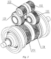
Fig. 3 is a schematic diagram of the internal structure of the speed reducer according to the invention. - 100. Integrated speed reducer; 110. Speed reducer housing; 120. First speed reducer; 121. First input shaft; 122. First input gear; 123. First output gear; 124. First intermediate reversing gear; 125. First sun gear; 126. First planetary gear; 127. First planet carrier; 128. First ring gear; 129. First ring gear lock; 130. Second speed reducer; 131. Second input shaft; 132. Second input gear; 133. Second output gear; 134. Second intermediate reversing gear; 135. Second sun gear; 136. Second planetary gear; 137. Second planet carrier; 138. Second ring gear; 139. Second ring gear lock; 210. First electric motor; 220. Second electric motor; 300. First axle shaft; 400. Second axle shaft.
- It should be understood by those skilled in the art that embodiments in this section are merely used to explain the technical principle of the invention and are not intended to limit the scope of protection of the invention. For example, although the power transmission system with dual electric motors and planetary gears of the invention is described in conjunction with a battery electric vehicle, the power transmission system with dual electric motors and planetary gears of the invention may also be applied to oil-electric hybrid vehicles and gas-electric hybrid vehicles. Those skilled in the art can make adjustments according to requirements, such that the power transmission system with dual electric motors and planetary gears can adapt to specific application occasions, and the adjusted technical solutions should still fall within the scope of protection of the invention.
- It should be noted that the terms herein that indicate the direction or positional relationship, such as "centre", "upper", "lower", "left", "right", "vertical", "horizontal", "inner" and "outer", are based on the direction or positional relationship shown in the figures, which is merely for ease of description and not to indicate or imply that the device or element must have a particular orientation and be constructed and operated in a particular orientation, and therefore, should not be construed as limiting the invention. In addition, the terms "first", "second" and "third" are for descriptive purposes only and should not be construed as indicating or implying relative importance.
- In addition, it should also be noted that, in the description of the invention, the terms "mount", "engage" and "connect" should be interpreted in a broad sense unless explicitly defined and limited otherwise, which, for example, can mean a fixed connection, a detachable connection or an integral connection; can mean a mechanical connection or an electrical connection; and can mean a direct connection, an indirect connection by means of an intermediary, or internal communication between two elements. For those skilled in the art, the specific meaning of the above terms in the invention can be interpreted according to the specific situation.
- As shown in
Fig. 1 , a power transmission system with dual electric motors and planetary gears for an electric vehicle of the invention mainly comprises a first power transmission subsystem (not labelled in the figure) and a second power transmission subsystem (not labelled in the figure) which are identical. The power transmission subsystem mainly comprises afirst speed reducer 120 and a firstelectric motor 210. Thefirst speed reducer 120 has an input end connected to an output shaft of the firstelectric motor 210, and thefirst speed reducer 120 has an output end connected to a wheel of an electric vehicle via afirst axle shaft 300. The second power transmission subsystem mainly comprises asecond speed reducer 130 and a secondelectric motor 220. Thesecond speed reducer 130 has an input end connected to an output shaft of the secondelectric motor 220, and thesecond speed reducer 130 has an output end connected to another wheel of the electric vehicle via asecond axle shaft 400. - Further, although not shown in the figure, the
first speed reducer 120, thesecond speed reducer 130, the firstelectric motor 210 and the secondelectric motor 220 of the invention are all arranged on a subframe of the electric vehicle such that thefirst speed reducer 120, thesecond speed reducer 130, the firstelectric motor 210 and the secondelectric motor 220 are all positioned above a shock-absorbing spring of the electric vehicle. Compared to the prior art where a hub motor is arranged below the shock-absorbing spring of the electric vehicle, the power transmission system with dual electric motors and planetary gears of the invention lowers the unsprung mass of the electric vehicle when applied thereto, so as to reduce the inertial force when the wheel is running over the uneven ground, thereby reducing the impact of the uneven ground on the vehicle body and enhancing the driving comfort of the electric vehicle. - In a preferable solution for carrying out the invention, the first power transmission subsystem and the second power transmission subsystem are identical. However, those skilled in the art can make appropriate adjustments on the first power transmission subsystem and the second power transmission subsystem according to requirements, for example, appropriate adjustments on the shapes and structures of the
first speed reducer 120 and thesecond speed reducer 130. The adjusted technical solutions do not deviate from the principle of the invention, and therefore should still fall within the scope of protection of the invention. - As shown in
Figs. 1 and2 , thefirst speed reducer 120 and thesecond speed reducer 130 are preferably provided as anintegrated speed reducer 100 such that the whole speed reducer has a more compact structure so as to reduce the space occupied by the whole speed reducer. - Preferably, as shown in
Fig. 2 , thefirst speed reducer 120 and thesecond speed reducer 130 are symmetrically provided inside aspeed reducer housing 110. - As shown in
Figs. 2 and3 , thefirst speed reducer 120 of the invention mainly comprises a first reduction mechanism (not labelled in the figure) and a second reduction mechanism (not labelled in the figure). The first reduction mechanism is a single-stage cylindrical gear reduction mechanism, which mainly comprises afirst input shaft 121, afirst input gear 122 and afirst output gear 123. Thefirst input shaft 121 is pivotally provided on thespeed reducer housing 110, and is also coaxially fixed to thefirst input gear 122, and thefirst input gear 122 and thefirst output gear 123 are engaged with each other. The second reduction mechanism is a planetary gear reduction mechanism, which mainly comprises a first intermediate reversinggear 124, afirst sun gear 125, firstplanetary gears 126, afirst planet carrier 127 and afirst ring gear 128. The first intermediate reversinggear 124 is engaged with thefirst output gear 123, and is also coaxially fixed to thefirst sun gear 125. Thefirst ring gear 128 is connected to thefirst sun gear 125 via the firstplanetary gears 126, and the firstplanetary gears 126 are then pivotally connected to thefirst planet carrier 127, respectively. - With continued reference to
Fig. 2 , thefirst speed reducer 120 further comprises a firstring gear lock 129 provided on thespeed reducer housing 110, and the firstring gear lock 129 is used to circumferentially fix thefirst ring gear 128. Specifically, when a bolt of the firstring gear lock 129 extends out, an end portion of the bolt can abut against and be tightly compressed against an outer side of thefirst ring gear 128 such that thefirst gear ring 128 is circumferentially fixed. When the bolt of the firstring gear lock 129 retracts back, the end portion of the bolt is separated from the outer side of thefirst ring gear 128 such that thefirst gear ring 128 can rotate freely. Those skilled in the art can understand that the locking between the bolt of the firstring gear lock 129 and thefirst ring gear 128 may be in any feasible way, for example, the locking by means of a friction force and by inserting the end portion of the bolt into a lock groove provided on the outer side of thefirst ring gear 128. - In a preferable technical solution of the invention, the first
ring gear lock 129 is an electrically controlled lock such that a controller of the electric vehicle can control the telescoping movement of the bolt of thefirst ring gear 129. - In addition, although not shown in the figures, the second reduction mechanism of the invention may be further provided with a separate housing for accommodating the
first sun gear 125, the firstplanetary gears 126, thefirst planet carrier 127 and thefirst ring gear 128. In this case, the firstring gear lock 129 is provided on this housing. - The power transmission process of the
first speed reducer 120 is described below in conjunction withFig. 2 . - As shown in
Fig. 2 , when the firstelectric motor 210 drives the wheel of the electric vehicle to rotate, the firstring gear lock 129 locks thefirst ring gear 128 to prevent thefirst ring gear 128 from rotating. The output shaft of the firstelectric motor 210 is coaxially fixed to thefirst input shaft 121, and drives thefirst input gear 122 to rotate via thefirst input shaft 121. The rotatingfirst input gear 122 drives thefirst output gear 123 to rotate by means of the engaged connection of the first input gear and thefirst output gear 123. The rotatingfirst output gear 123 drives thefirst sun gear 125 to rotate by means of the engaged connection of the first output gear and the first intermediate reversinggear 124. Since thefirst ring gear 128 is locked, the rotatingfirst sun gear 125 drives the firstplanetary gears 126 to rotate in an opposite direction by means of the engaged connection of the first sun gear and the firstplanetary gears 126. The rotating firstplanetary gears 126 drive thefirst planet carrier 127 to rotate. The rotatingfirst planet carrier 127 drives the wheel to rotate via thefirst axle shaft 300 which is connected to the left end of thefirst planet carrier 127 as shown inFig. 2 . - When the first
electric motor 210 malfunctions and cannot supply power to thefirst speed reducer 120, the controller of the electric vehicle unlocks the firstring gear lock 129 to release thefirst ring gear 128, such that thefirst ring gear 128 can rotate freely. In this case, thefirst sun gear 125 cannot drive thefirst planet carrier 127 to rotate by means of thefirst ring gear 128 and the firstplanetary gears 126. The power transmission between the firstelectric motor 210 in driving connection with thefirst sun gear 125 and the wheel in driving connection with thefirst planet carrier 127 is therefore interrupted, such that the wheel can rotate freely, thereby eliminating the resistance applied by the malfunctioned firstelectric motor 210 to the electric vehicle when the electric vehicle is running. - It should be noted that the power transmission relationship between the
first sun gear 125, the firstplanetary gears 126, thefirst planet carrier 127 and thefirst ring gear 128 when the firstring gear lock 129 is unlocked is not described in detail here because the working principle of the planetary speed reducer is known by those skilled in the art. - With continued reference to
Figs. 2 and3 , thesecond speed reducer 130 of the invention mainly comprises a third reduction mechanism (not labelled in the figures) symmetric to the first reduction mechanism and a fourth reduction mechanism (not labelled in the figures) symmetric to the second reduction mechanism. The third reduction mechanism is a single-stage cylindrical gear reduction mechanism, which mainly comprises asecond input shaft 131, asecond input gear 132 and asecond output gear 133. Thesecond input shaft 131 is pivotally provided on thespeed reducer housing 110, and is also coaxially fixed to thesecond input gear 132, and thesecond input gear 132 and thesecond output gear 133 are engaged with each other. The fourth reduction mechanism is a planetary gear reduction mechanism, which mainly comprises a second intermediate reversinggear 134, asecond sun gear 135, secondplanetary gears 136, asecond planet carrier 137 and asecond ring gear 138. The second intermediate reversinggear 134 is engaged with thesecond output gear 133, and is also coaxially fixed to thesecond sun gear 135. Thesecond ring gear 138 is connected to thesecond sun gear 135 via the secondplanetary gears 136, and the secondplanetary gears 136 are then pivotally connected to thesecond planet carrier 137, respectively. - With continued reference to
Fig. 2 , thesecond speed reducer 130 further comprises a secondring gear lock 139 provided on thespeed reducer housing 110, and the secondring gear lock 139 is used to circumferentially fix thesecond ring gear 138. Specifically, when a bolt of the secondring gear lock 139 extends out, an end portion of the bolt can abut against and be tightly compressed against an outer side of thesecond ring gear 138 such that thesecond gear ring 138 is circumferentially fixed. When the bolt of the secondring gear lock 139 retracts back, the end portion of the bolt is separated from the outer side of thesecond ring gear 138 such that thesecond gear ring 138 can rotate freely. Those skilled in the art can understand that the locking between the bolt of the secondring gear lock 139 and thesecond ring gear 138 may be in any feasible way, for example, the locking by means of a friction force and by inserting the end portion of the bolt into a lock groove provided on the outer side of thesecond ring gear 138. - In a preferable technical solution of the invention, the second
ring gear lock 139 is an electrically controlled lock such that a controller of the electric vehicle can control the telescoping movement of the bolt of thesecond ring gear 139. - In addition, although not shown in the figures, the second reduction mechanism of the invention may be further provided with a separate housing for accommodating the
second sun gear 135, the secondplanetary gears 136, thesecond planet carrier 137 and thesecond ring gear 138. In this case, the secondring gear lock 139 is provided on this housing. - The power transmission process of the
second speed reducer 130 is described below in conjunction withFig. 2 . - As shown in
Fig. 2 , when the secondelectric motor 220 drives the wheel of the electric vehicle to rotate, the secondring gear lock 139 locks thesecond ring gear 138 to prevent thesecond ring gear 138 from rotating. The output shaft of the secondelectric motor 220 is coaxially fixed to thesecond input shaft 131, and drives thesecond input gear 132 to rotate via thesecond input shaft 131. The rotatingsecond input gear 132 drives thesecond output gear 133 to rotate by means of the engaged connection of the second input gear and thesecond output gear 133. The rotatingsecond output gear 133 drives thesecond sun gear 135 to rotate by means of the engaged connection of the second output gear and the second intermediate reversinggear 134. Since thesecond ring gear 138 is locked, the rotatingsecond sun gear 135 drives the secondplanetary gears 136 to rotate in an opposite direction by means of the engaged connection of the second sun gear and the secondplanetary gears 136. The rotating secondplanetary gears 136 drive thesecond planet carrier 137 to rotate. The rotatingsecond planet carrier 137 drives the wheel to rotate via thesecond axle shaft 400 which is connected to the left end of thesecond planet carrier 137 as shown inFig. 2 . - When the second
electric motor 220 malfunctions and cannot supply power to thesecond speed reducer 130, the controller of the electric vehicle unlocks the secondring gear lock 139 to release thesecond ring gear 138, such that thesecond ring gear 138 can rotate freely. In this case, thesecond sun gear 135 cannot drive thesecond planet carrier 137 to rotate by means of thesecond ring gear 138 and the secondplanetary gears 136. The power transmission between the secondelectric motor 220 in driving connection with thesecond sun gear 135 and the wheel in driving connection with thesecond planet carrier 137 is therefore interrupted, such that the wheel can rotate freely, thereby eliminating the resistance applied by the malfunctioned secondelectric motor 220 to the electric vehicle when the electric vehicle is running. - It should be noted that the power transmission relationship between the
second sun gear 135, the secondplanetary gears 136, thesecond planet carrier 137 and thesecond ring gear 138 when the secondring gear lock 139 is unlocked is not described in detail here because the working principle of the planetary speed reducer is known by those skilled in the art. - Those skilled in the art can understand that, when applied to the electric vehicle, the power transmission system with dual electric motors and planetary gears of the invention can ensure that, during the normal running of the electric vehicle, and when a certain power motor (the first
electric motor 210 or the second electric motor 220) malfunctions, unlocking the ring gear (thefirst ring gear 128 or the second ring gear 138) from the ring gear lock (the firstring gear lock 129 or the second ring gear lock 139) can interrupt the power connection between the power motor and the corresponding wheel. In this way, it is ensured that the malfunctioned power motor does not apply resistance to the running electric vehicle, and the running resistance to the vehicle is thus reduced. - Those skilled in the art can also understand that the power transmission system with dual electric motors and planetary gears of the invention can not only be applied to battery electric vehicles to allow the battery electric vehicles to have front-wheel drive, rear-wheel drive or four-wheel drive power output, but also be applied to oil-electric hybrid vehicles and gas-electric hybrid vehicles.
- Further, in a preferable embodiment of the invention, the first
electric motor 210 and the secondelectric motor 220 are two permanent magnet synchronous motors which are identical in structure and performance. Alternatively, those skilled in the art can replace the firstelectric motor 210 and the secondelectric motor 220 described above by electric motors in any other form such as servo motors according to requirements. - In summary, the power transmission system with dual electric motors and planetary gears of the invention can allow each of the driving wheels of the electric vehicle to be respectively driven by a separate electric motor so as to effectively control the output torque of each of the wheels; moreover, the configuration of the single-stage cylindrical gear reduction mechanism and the planetary gear reduction mechanisms can also enable the
speed reducer 100 to have a relatively high reduction ratio while having a compact layout space, such that the electric vehicle can obtain a higher low-speed performance. - Heretofore, the technical solutions of the invention have been described with reference to the preferred embodiments shown in the accompanying drawings; however, those skilled in the art can readily understand that the scope of protection of the invention is obviously not limited to these particular embodiments. Those skilled in the art can make equivalent changes or substitutions to the related technical features without departing from the principles of the invention, and all the technical solutions after the changes or substitutions will fall within the scope of protection of the invention.
Claims (12)
- A power transmission system with dual electric motors and planetary gears for an electric vehicle, characterized in that the power transmission system comprises at least one power transmission subsystem;
the power transmission subsystem comprising an electric motor and a speed reducer,
wherein the speed reducer comprises a first reduction mechanism and a second reduction mechanism,
the first reduction mechanism has an input end connected to an output shaft of the electric motor, the first reduction mechanism has an output end connected to an input end of the second reduction mechanism, and the second reduction mechanism has an output end connected to an axle shaft of the electric vehicle. - The power transmission system with dual electric motors and planetary gears for an electric vehicle according to claim 1, characterized in that the first reduction mechanism is a single-stage cylindrical gear reduction mechanism.
- The power transmission system with dual electric motors and planetary gears for an electric vehicle according to claim 2, characterized in that the single-stage cylindrical gear reduction mechanism comprises a first input gear and a first output gear which are engaged with each other,
wherein the first input gear is in driving connection with the output shaft of the electric motor,
and the first output gear is in driving connection with the input end of the second reduction mechanism. - The power transmission system with dual electric motors and planetary gears for an electric vehicle according to claim 3, characterized in that the singe-stage cylindrical gear reduction mechanism further comprises a first input shaft coaxially fixed to the first input gear, and the first input shaft is coaxially fixed and connected to the output shaft of the electric motor.
- The power transmission system with dual electric motors and planetary gears for an electric vehicle according to any one of claims 1 to 4, characterized in that the second reduction mechanism is a planetary gear reduction mechanism.
- The power transmission system with dual electric motors and planetary gears for an electric vehicle according to claim 5, characterized in that the planetary gear reduction mechanism comprises a housing, and a ring gear, planetary gears and a sun gear which are arranged inside the housing in sequence from the outside to the inside,
wherein the sun gear is connected to the output end of the first reduction mechanism;
the planetary gears are respectively engaged with the sun gear and the ring gear, and are connected to the axle shaft via a planet carrier; and
the ring gear is connected to the housing. - The power transmission system with dual electric motors and planetary gears for an electric vehicle according to claim 6, characterized in that the planetary gear reduction mechanism further comprises a ring gear lock arranged on the housing,
when the ring gear lock is locked, the ring gear is circumferentially fixed to the housing via the ring gear lock; and
when the ring gear lock is unlocked, the ring gear is capable of rotating about its own axis. - The power transmission system with dual electric motors and planetary gears for an electric vehicle according to claim 7, characterized in that the ring gear lock is an electrically controlled lock.
- The power transmission system with dual electric motors and planetary gears for an electric vehicle according to claim 6, characterized in that the planetary gear reduction mechanism further comprises an intermediate reversing gear coaxially fixed to the sun gear, and the sun gear is connected to the output end of the first reduction mechanism via the intermediate reversing gear.
- The power transmission system with dual electric motors and planetary gears for an electric vehicle according to any one of claims 1 to 4, characterized in that the power transmission system comprises two identical power transmission subsystems, and the two power transmission subsystems are arranged symmetrically.
- An electric vehicle, characterized by comprising a power transmission system with dual electric motors and planetary gears for an electric vehicle according to any one of claims 1 to 8.
- The electric vehicle according to claim 11, characterized in that the electric motor and the speed reducer are both arranged on a subframe of the electric vehicle.
Applications Claiming Priority (2)
| Application Number | Priority Date | Filing Date | Title |
|---|---|---|---|
| CN201810155678.5A CN108528186B (en) | 2018-02-23 | 2018-02-23 | Electric vehicle and its dual-motor planetary gear powertrain |
| PCT/CN2019/074415 WO2019161738A1 (en) | 2018-02-23 | 2019-02-01 | Electric vehicle and dual-motor planet gear power transmission system thereof |
Publications (3)
| Publication Number | Publication Date |
|---|---|
| EP3756920A1 true EP3756920A1 (en) | 2020-12-30 |
| EP3756920A4 EP3756920A4 (en) | 2021-05-19 |
| EP3756920B1 EP3756920B1 (en) | 2024-05-08 |
Family
ID=63486202
Family Applications (1)
| Application Number | Title | Priority Date | Filing Date |
|---|---|---|---|
| EP19758233.1A Active EP3756920B1 (en) | 2018-02-23 | 2019-02-01 | Electric vehicle and dual-motor planet gear power transmission system thereof |
Country Status (3)
| Country | Link |
|---|---|
| EP (1) | EP3756920B1 (en) |
| CN (1) | CN108528186B (en) |
| WO (1) | WO2019161738A1 (en) |
Cited By (2)
| Publication number | Priority date | Publication date | Assignee | Title |
|---|---|---|---|---|
| WO2024052478A1 (en) * | 2022-09-09 | 2024-03-14 | Trailer Dynamics Gmbh | Electric powertrain for a commercial vehicle with two electric motors |
| DE102023108554B3 (en) | 2023-04-04 | 2024-05-08 | Audi Aktiengesellschaft | Crown gear transmission |
Families Citing this family (24)
| Publication number | Priority date | Publication date | Assignee | Title |
|---|---|---|---|---|
| CN108528186B (en) * | 2018-02-23 | 2021-07-23 | 蔚来(安徽)控股有限公司 | Electric vehicle and its dual-motor planetary gear powertrain |
| CN111173892B (en) * | 2018-11-12 | 2021-12-14 | 华为技术有限公司 | Vehicle and its powertrain system |
| WO2020181671A1 (en) * | 2019-03-11 | 2020-09-17 | 南京越博动力系统股份有限公司 | Dual motor transaxle case |
| CN110758076A (en) * | 2019-11-11 | 2020-02-07 | 北京理工大学 | A four-wheel independent drive system for a new energy vehicle |
| CN112937273B (en) * | 2019-12-10 | 2023-01-20 | 中车时代电动汽车股份有限公司 | Electric drive axle assembly device |
| CN111114269A (en) * | 2020-01-21 | 2020-05-08 | 上海爱驱汽车技术有限公司 | Double-motor distributed driving system and vehicle |
| CN118107365B (en) * | 2020-11-30 | 2025-04-08 | 比亚迪股份有限公司 | Wheel drive assembly and vehicle |
| CN112659890A (en) * | 2020-12-31 | 2021-04-16 | 华人运通(江苏)技术有限公司 | Variable speed transmission system, driving system, power system and vehicle |
| CN113147342A (en) * | 2021-03-09 | 2021-07-23 | 江苏米孚自动化科技有限公司 | Pure electric drive ore deposit is bi-motor for truck |
| US11565586B2 (en) * | 2021-03-25 | 2023-01-31 | Rivian Ip Holdings, Llc | Modular high-low range gearbox attachment |
| CN114290889A (en) * | 2021-06-30 | 2022-04-08 | 华为数字能源技术有限公司 | Power device and vehicle |
| CN113400912B (en) * | 2021-07-07 | 2023-10-10 | 方银元 | Traction wheel type motor unit |
| DE102021208174A1 (en) | 2021-07-29 | 2023-02-02 | Zf Friedrichshafen Ag | Drive assembly for a vehicle and vehicle with the drive assembly |
| CN113954614A (en) * | 2021-09-22 | 2022-01-21 | 江苏英拓动力科技有限公司 | Method for increasing power density of electric drive vehicle transmission system and transmission system using the same |
| CN113719586B (en) * | 2021-11-01 | 2022-05-20 | 深圳电通信息技术有限公司 | Speed reducer gear assembly for new energy vehicle |
| CN114393990A (en) * | 2021-12-21 | 2022-04-26 | 徐州博汇世通重工机械有限责任公司 | Double-motor-driven wheel type chassis |
| CN114211951B (en) * | 2021-12-21 | 2024-08-23 | 吉林大学 | Electric wheel structure with reducer |
| CN114572331B (en) * | 2022-02-25 | 2024-05-24 | 浙江夏厦精密制造股份有限公司 | Low-noise electric scooter |
| WO2023173318A1 (en) * | 2022-03-16 | 2023-09-21 | 舍弗勒技术股份两合公司 | Bridge driving system and vehicle |
| CN114851831A (en) * | 2022-04-18 | 2022-08-05 | 索特传动设备有限公司 | Four-wheel drive system and construction machinery |
| CN116080379A (en) * | 2022-12-16 | 2023-05-09 | 上海艾福亿维新能源科技有限公司 | Distributed dual motor drive system and vehicle |
| CN115973263B (en) * | 2022-12-20 | 2024-07-16 | 吉林大学 | A redundant dual-motor steering mechanism and control method thereof |
| CN116494743B (en) * | 2023-06-12 | 2024-04-16 | 中国重汽集团济南动力有限公司 | Electric drive axle system and car |
| CN117284067A (en) * | 2023-10-08 | 2023-12-26 | 东风汽车集团股份有限公司 | Vehicle distributed drive system and drive assembly |
Family Cites Families (12)
| Publication number | Priority date | Publication date | Assignee | Title |
|---|---|---|---|---|
| DE4434237A1 (en) * | 1994-09-24 | 1996-03-28 | Deere & Co | Vehicle axle with wheels powered by individual electric drives |
| JP2005104215A (en) * | 2003-09-29 | 2005-04-21 | Nissan Motor Co Ltd | Vehicle drive device |
| CN200977848Y (en) * | 2006-06-27 | 2007-11-21 | 杭州三园工具有限公司 | Electric vehicle chassis |
| CN101519040B (en) * | 2008-05-23 | 2012-12-05 | 北京理工大学 | Double-motor skidproof differential drive axle of electric automobile |
| CN102848908B (en) * | 2012-09-19 | 2015-05-13 | 长城汽车股份有限公司 | Power driving device of electric vehicle and electric vehicle |
| DE102016201223A1 (en) * | 2016-01-28 | 2017-03-09 | Schaeffler Technologies AG & Co. KG | Planetary gear for a motor vehicle |
| US11186162B2 (en) * | 2016-03-15 | 2021-11-30 | Borgwarner, Inc. | Twin system electric all-wheel drive supplementary drive axle |
| CN206600423U (en) * | 2017-01-23 | 2017-10-31 | 陕西工业职业技术学院 | Bi-motor continuous driving force couples gearbox |
| CN107054036A (en) * | 2017-02-22 | 2017-08-18 | 吉林大学 | A kind of driving device for pure electric vehicles and driving method |
| CN206889591U (en) * | 2017-07-06 | 2018-01-16 | 深圳市华宏昊科技有限公司 | A kind of planet gear reducing mechanism and its decelerator |
| CN108528186B (en) * | 2018-02-23 | 2021-07-23 | 蔚来(安徽)控股有限公司 | Electric vehicle and its dual-motor planetary gear powertrain |
| DE102018005947A1 (en) * | 2018-07-27 | 2020-01-30 | Daimler Ag | Electric drive train for a motor vehicle, in particular for a motor vehicle |
-
2018
- 2018-02-23 CN CN201810155678.5A patent/CN108528186B/en active Active
-
2019
- 2019-02-01 WO PCT/CN2019/074415 patent/WO2019161738A1/en not_active Ceased
- 2019-02-01 EP EP19758233.1A patent/EP3756920B1/en active Active
Cited By (2)
| Publication number | Priority date | Publication date | Assignee | Title |
|---|---|---|---|---|
| WO2024052478A1 (en) * | 2022-09-09 | 2024-03-14 | Trailer Dynamics Gmbh | Electric powertrain for a commercial vehicle with two electric motors |
| DE102023108554B3 (en) | 2023-04-04 | 2024-05-08 | Audi Aktiengesellschaft | Crown gear transmission |
Also Published As
| Publication number | Publication date |
|---|---|
| EP3756920A4 (en) | 2021-05-19 |
| EP3756920B1 (en) | 2024-05-08 |
| CN108528186B (en) | 2021-07-23 |
| CN108528186A (en) | 2018-09-14 |
| WO2019161738A1 (en) | 2019-08-29 |
Similar Documents
| Publication | Publication Date | Title |
|---|---|---|
| EP3756920B1 (en) | Electric vehicle and dual-motor planet gear power transmission system thereof | |
| KR102580735B1 (en) | Axle assembly for low-floor vehicles | |
| US8640801B2 (en) | Propulsion device for automobile with portal axle comprising an electrical machine | |
| CN103373342B (en) | Distinguish the system and method for the moment of torsion between wheel | |
| CN113173065A (en) | Dual-motor driving system and electric automobile | |
| EP4124490B1 (en) | Selectable differential drive for a vehicle | |
| JP5343047B2 (en) | Vehicle comprising vehicle drive device and rotating electric machine | |
| CN108790936A (en) | A kind of power coupling drive system, electric vehicle and control method | |
| JP6097494B2 (en) | Electric vehicle drive system | |
| CN104487272A (en) | Motorized hub comprising a change in ratio and coupling and uncoupling means | |
| JP2012091759A (en) | Vehicle drive device | |
| WO2025077287A1 (en) | Distributed drive system of vehicle and drive assembly | |
| US12030377B2 (en) | Electric powertrain for a vehicle | |
| CN116455132A (en) | Motor, power assembly and vehicle | |
| KR101305012B1 (en) | In-wheel driving system and method for controling the same | |
| JPH04243627A (en) | Auxiliary drive type vehicle | |
| US20240278634A1 (en) | Power transmission assembly and vehicle comprising this assembly | |
| JPH05116541A (en) | Drive unit for electric car | |
| JP2991009B2 (en) | Right and left driving force distribution adjustment device for vehicles | |
| CN222291502U (en) | Drive device and vehicle | |
| CN223302515U (en) | Integrated integration system for distributed driving and braking and vehicle | |
| CN217347389U (en) | Driving system and hovercar | |
| CN223803409U (en) | Powertrain and Vehicles | |
| CN118438877A (en) | Drive device and vehicle | |
| CN217227201U (en) | Integrated electric drive axle |
Legal Events
| Date | Code | Title | Description |
|---|---|---|---|
| STAA | Information on the status of an ep patent application or granted ep patent |
Free format text: STATUS: THE INTERNATIONAL PUBLICATION HAS BEEN MADE |
|
| PUAI | Public reference made under article 153(3) epc to a published international application that has entered the european phase |
Free format text: ORIGINAL CODE: 0009012 |
|
| STAA | Information on the status of an ep patent application or granted ep patent |
Free format text: STATUS: REQUEST FOR EXAMINATION WAS MADE |
|
| 17P | Request for examination filed |
Effective date: 20200923 |
|
| AK | Designated contracting states |
Kind code of ref document: A1 Designated state(s): AL AT BE BG CH CY CZ DE DK EE ES FI FR GB GR HR HU IE IS IT LI LT LU LV MC MK MT NL NO PL PT RO RS SE SI SK SM TR |
|
| AX | Request for extension of the european patent |
Extension state: BA ME |
|
| A4 | Supplementary search report drawn up and despatched |
Effective date: 20210416 |
|
| RIC1 | Information provided on ipc code assigned before grant |
Ipc: B60K 1/02 20060101AFI20210412BHEP Ipc: B60K 17/04 20060101ALI20210412BHEP Ipc: F16H 37/04 20060101ALI20210412BHEP Ipc: F16H 57/10 20060101ALI20210412BHEP Ipc: F16H 3/54 20060101ALN20210412BHEP |
|
| DAV | Request for validation of the european patent (deleted) | ||
| DAX | Request for extension of the european patent (deleted) | ||
| STAA | Information on the status of an ep patent application or granted ep patent |
Free format text: STATUS: EXAMINATION IS IN PROGRESS |
|
| 17Q | First examination report despatched |
Effective date: 20220919 |
|
| GRAP | Despatch of communication of intention to grant a patent |
Free format text: ORIGINAL CODE: EPIDOSNIGR1 |
|
| STAA | Information on the status of an ep patent application or granted ep patent |
Free format text: STATUS: GRANT OF PATENT IS INTENDED |
|
| RIC1 | Information provided on ipc code assigned before grant |
Ipc: F16H 3/54 20060101ALN20231130BHEP Ipc: F16H 57/10 20060101ALI20231130BHEP Ipc: F16H 37/04 20060101ALI20231130BHEP Ipc: B60K 17/04 20060101ALI20231130BHEP Ipc: B60K 1/02 20060101AFI20231130BHEP |
|
| INTG | Intention to grant announced |
Effective date: 20231214 |
|
| RIC1 | Information provided on ipc code assigned before grant |
Ipc: F16H 3/54 20060101ALN20231206BHEP Ipc: F16H 57/10 20060101ALI20231206BHEP Ipc: F16H 37/04 20060101ALI20231206BHEP Ipc: B60K 17/04 20060101ALI20231206BHEP Ipc: B60K 1/02 20060101AFI20231206BHEP |
|
| GRAS | Grant fee paid |
Free format text: ORIGINAL CODE: EPIDOSNIGR3 |
|
| GRAA | (expected) grant |
Free format text: ORIGINAL CODE: 0009210 |
|
| STAA | Information on the status of an ep patent application or granted ep patent |
Free format text: STATUS: THE PATENT HAS BEEN GRANTED |
|
| AK | Designated contracting states |
Kind code of ref document: B1 Designated state(s): AL AT BE BG CH CY CZ DE DK EE ES FI FR GB GR HR HU IE IS IT LI LT LU LV MC MK MT NL NO PL PT RO RS SE SI SK SM TR |
|
| REG | Reference to a national code |
Ref country code: GB Ref legal event code: FG4D |
|
| REG | Reference to a national code |
Ref country code: CH Ref legal event code: EP |
|
| REG | Reference to a national code |
Ref country code: DE Ref legal event code: R096 Ref document number: 602019051951 Country of ref document: DE |
|
| REG | Reference to a national code |
Ref country code: IE Ref legal event code: FG4D |
|
| REG | Reference to a national code |
Ref country code: LT Ref legal event code: MG9D |
|
| REG | Reference to a national code |
Ref country code: NL Ref legal event code: MP Effective date: 20240508 |
|
| PG25 | Lapsed in a contracting state [announced via postgrant information from national office to epo] |
Ref country code: IS Free format text: LAPSE BECAUSE OF FAILURE TO SUBMIT A TRANSLATION OF THE DESCRIPTION OR TO PAY THE FEE WITHIN THE PRESCRIBED TIME-LIMIT Effective date: 20240908 |
|
| PG25 | Lapsed in a contracting state [announced via postgrant information from national office to epo] |
Ref country code: BG Free format text: LAPSE BECAUSE OF FAILURE TO SUBMIT A TRANSLATION OF THE DESCRIPTION OR TO PAY THE FEE WITHIN THE PRESCRIBED TIME-LIMIT Effective date: 20240508 |
|
| PG25 | Lapsed in a contracting state [announced via postgrant information from national office to epo] |
Ref country code: FI Free format text: LAPSE BECAUSE OF FAILURE TO SUBMIT A TRANSLATION OF THE DESCRIPTION OR TO PAY THE FEE WITHIN THE PRESCRIBED TIME-LIMIT Effective date: 20240508 Ref country code: HR Free format text: LAPSE BECAUSE OF FAILURE TO SUBMIT A TRANSLATION OF THE DESCRIPTION OR TO PAY THE FEE WITHIN THE PRESCRIBED TIME-LIMIT Effective date: 20240508 |
|
| PG25 | Lapsed in a contracting state [announced via postgrant information from national office to epo] |
Ref country code: GR Free format text: LAPSE BECAUSE OF FAILURE TO SUBMIT A TRANSLATION OF THE DESCRIPTION OR TO PAY THE FEE WITHIN THE PRESCRIBED TIME-LIMIT Effective date: 20240809 |
|
| PG25 | Lapsed in a contracting state [announced via postgrant information from national office to epo] |
Ref country code: PT Free format text: LAPSE BECAUSE OF FAILURE TO SUBMIT A TRANSLATION OF THE DESCRIPTION OR TO PAY THE FEE WITHIN THE PRESCRIBED TIME-LIMIT Effective date: 20240909 |
|
| REG | Reference to a national code |
Ref country code: AT Ref legal event code: MK05 Ref document number: 1684727 Country of ref document: AT Kind code of ref document: T Effective date: 20240508 |
|
| PG25 | Lapsed in a contracting state [announced via postgrant information from national office to epo] |
Ref country code: NL Free format text: LAPSE BECAUSE OF FAILURE TO SUBMIT A TRANSLATION OF THE DESCRIPTION OR TO PAY THE FEE WITHIN THE PRESCRIBED TIME-LIMIT Effective date: 20240508 |
|
| PG25 | Lapsed in a contracting state [announced via postgrant information from national office to epo] |
Ref country code: ES Free format text: LAPSE BECAUSE OF FAILURE TO SUBMIT A TRANSLATION OF THE DESCRIPTION OR TO PAY THE FEE WITHIN THE PRESCRIBED TIME-LIMIT Effective date: 20240508 |
|
| PG25 | Lapsed in a contracting state [announced via postgrant information from national office to epo] |
Ref country code: AT Free format text: LAPSE BECAUSE OF FAILURE TO SUBMIT A TRANSLATION OF THE DESCRIPTION OR TO PAY THE FEE WITHIN THE PRESCRIBED TIME-LIMIT Effective date: 20240508 |
|
| PG25 | Lapsed in a contracting state [announced via postgrant information from national office to epo] |
Ref country code: PL Free format text: LAPSE BECAUSE OF FAILURE TO SUBMIT A TRANSLATION OF THE DESCRIPTION OR TO PAY THE FEE WITHIN THE PRESCRIBED TIME-LIMIT Effective date: 20240508 |
|
| PG25 | Lapsed in a contracting state [announced via postgrant information from national office to epo] |
Ref country code: LV Free format text: LAPSE BECAUSE OF FAILURE TO SUBMIT A TRANSLATION OF THE DESCRIPTION OR TO PAY THE FEE WITHIN THE PRESCRIBED TIME-LIMIT Effective date: 20240508 |
|
| PG25 | Lapsed in a contracting state [announced via postgrant information from national office to epo] |
Ref country code: PT Free format text: LAPSE BECAUSE OF FAILURE TO SUBMIT A TRANSLATION OF THE DESCRIPTION OR TO PAY THE FEE WITHIN THE PRESCRIBED TIME-LIMIT Effective date: 20240909 Ref country code: PL Free format text: LAPSE BECAUSE OF FAILURE TO SUBMIT A TRANSLATION OF THE DESCRIPTION OR TO PAY THE FEE WITHIN THE PRESCRIBED TIME-LIMIT Effective date: 20240508 Ref country code: NO Free format text: LAPSE BECAUSE OF FAILURE TO SUBMIT A TRANSLATION OF THE DESCRIPTION OR TO PAY THE FEE WITHIN THE PRESCRIBED TIME-LIMIT Effective date: 20240808 Ref country code: NL Free format text: LAPSE BECAUSE OF FAILURE TO SUBMIT A TRANSLATION OF THE DESCRIPTION OR TO PAY THE FEE WITHIN THE PRESCRIBED TIME-LIMIT Effective date: 20240508 Ref country code: LV Free format text: LAPSE BECAUSE OF FAILURE TO SUBMIT A TRANSLATION OF THE DESCRIPTION OR TO PAY THE FEE WITHIN THE PRESCRIBED TIME-LIMIT Effective date: 20240508 Ref country code: IS Free format text: LAPSE BECAUSE OF FAILURE TO SUBMIT A TRANSLATION OF THE DESCRIPTION OR TO PAY THE FEE WITHIN THE PRESCRIBED TIME-LIMIT Effective date: 20240908 Ref country code: HR Free format text: LAPSE BECAUSE OF FAILURE TO SUBMIT A TRANSLATION OF THE DESCRIPTION OR TO PAY THE FEE WITHIN THE PRESCRIBED TIME-LIMIT Effective date: 20240508 Ref country code: GR Free format text: LAPSE BECAUSE OF FAILURE TO SUBMIT A TRANSLATION OF THE DESCRIPTION OR TO PAY THE FEE WITHIN THE PRESCRIBED TIME-LIMIT Effective date: 20240809 Ref country code: FI Free format text: LAPSE BECAUSE OF FAILURE TO SUBMIT A TRANSLATION OF THE DESCRIPTION OR TO PAY THE FEE WITHIN THE PRESCRIBED TIME-LIMIT Effective date: 20240508 Ref country code: ES Free format text: LAPSE BECAUSE OF FAILURE TO SUBMIT A TRANSLATION OF THE DESCRIPTION OR TO PAY THE FEE WITHIN THE PRESCRIBED TIME-LIMIT Effective date: 20240508 Ref country code: BG Free format text: LAPSE BECAUSE OF FAILURE TO SUBMIT A TRANSLATION OF THE DESCRIPTION OR TO PAY THE FEE WITHIN THE PRESCRIBED TIME-LIMIT Effective date: 20240508 Ref country code: AT Free format text: LAPSE BECAUSE OF FAILURE TO SUBMIT A TRANSLATION OF THE DESCRIPTION OR TO PAY THE FEE WITHIN THE PRESCRIBED TIME-LIMIT Effective date: 20240508 Ref country code: RS Free format text: LAPSE BECAUSE OF FAILURE TO SUBMIT A TRANSLATION OF THE DESCRIPTION OR TO PAY THE FEE WITHIN THE PRESCRIBED TIME-LIMIT Effective date: 20240808 |
|
| PG25 | Lapsed in a contracting state [announced via postgrant information from national office to epo] |
Ref country code: DK Free format text: LAPSE BECAUSE OF FAILURE TO SUBMIT A TRANSLATION OF THE DESCRIPTION OR TO PAY THE FEE WITHIN THE PRESCRIBED TIME-LIMIT Effective date: 20240508 |
|
| PG25 | Lapsed in a contracting state [announced via postgrant information from national office to epo] |
Ref country code: EE Free format text: LAPSE BECAUSE OF FAILURE TO SUBMIT A TRANSLATION OF THE DESCRIPTION OR TO PAY THE FEE WITHIN THE PRESCRIBED TIME-LIMIT Effective date: 20240508 |
|
| PG25 | Lapsed in a contracting state [announced via postgrant information from national office to epo] |
Ref country code: CZ Free format text: LAPSE BECAUSE OF FAILURE TO SUBMIT A TRANSLATION OF THE DESCRIPTION OR TO PAY THE FEE WITHIN THE PRESCRIBED TIME-LIMIT Effective date: 20240508 |
|
| PG25 | Lapsed in a contracting state [announced via postgrant information from national office to epo] |
Ref country code: SK Free format text: LAPSE BECAUSE OF FAILURE TO SUBMIT A TRANSLATION OF THE DESCRIPTION OR TO PAY THE FEE WITHIN THE PRESCRIBED TIME-LIMIT Effective date: 20240508 Ref country code: RO Free format text: LAPSE BECAUSE OF FAILURE TO SUBMIT A TRANSLATION OF THE DESCRIPTION OR TO PAY THE FEE WITHIN THE PRESCRIBED TIME-LIMIT Effective date: 20240508 |
|
| PG25 | Lapsed in a contracting state [announced via postgrant information from national office to epo] |
Ref country code: SM Free format text: LAPSE BECAUSE OF FAILURE TO SUBMIT A TRANSLATION OF THE DESCRIPTION OR TO PAY THE FEE WITHIN THE PRESCRIBED TIME-LIMIT Effective date: 20240508 |
|
| PG25 | Lapsed in a contracting state [announced via postgrant information from national office to epo] |
Ref country code: SM Free format text: LAPSE BECAUSE OF FAILURE TO SUBMIT A TRANSLATION OF THE DESCRIPTION OR TO PAY THE FEE WITHIN THE PRESCRIBED TIME-LIMIT Effective date: 20240508 Ref country code: SK Free format text: LAPSE BECAUSE OF FAILURE TO SUBMIT A TRANSLATION OF THE DESCRIPTION OR TO PAY THE FEE WITHIN THE PRESCRIBED TIME-LIMIT Effective date: 20240508 Ref country code: RO Free format text: LAPSE BECAUSE OF FAILURE TO SUBMIT A TRANSLATION OF THE DESCRIPTION OR TO PAY THE FEE WITHIN THE PRESCRIBED TIME-LIMIT Effective date: 20240508 Ref country code: EE Free format text: LAPSE BECAUSE OF FAILURE TO SUBMIT A TRANSLATION OF THE DESCRIPTION OR TO PAY THE FEE WITHIN THE PRESCRIBED TIME-LIMIT Effective date: 20240508 Ref country code: DK Free format text: LAPSE BECAUSE OF FAILURE TO SUBMIT A TRANSLATION OF THE DESCRIPTION OR TO PAY THE FEE WITHIN THE PRESCRIBED TIME-LIMIT Effective date: 20240508 Ref country code: CZ Free format text: LAPSE BECAUSE OF FAILURE TO SUBMIT A TRANSLATION OF THE DESCRIPTION OR TO PAY THE FEE WITHIN THE PRESCRIBED TIME-LIMIT Effective date: 20240508 |
|
| PG25 | Lapsed in a contracting state [announced via postgrant information from national office to epo] |
Ref country code: IT Free format text: LAPSE BECAUSE OF FAILURE TO SUBMIT A TRANSLATION OF THE DESCRIPTION OR TO PAY THE FEE WITHIN THE PRESCRIBED TIME-LIMIT Effective date: 20240508 |
|
| REG | Reference to a national code |
Ref country code: DE Ref legal event code: R097 Ref document number: 602019051951 Country of ref document: DE |
|
| PLBE | No opposition filed within time limit |
Free format text: ORIGINAL CODE: 0009261 |
|
| STAA | Information on the status of an ep patent application or granted ep patent |
Free format text: STATUS: NO OPPOSITION FILED WITHIN TIME LIMIT |
|
| 26N | No opposition filed |
Effective date: 20250211 |
|
| PG25 | Lapsed in a contracting state [announced via postgrant information from national office to epo] |
Ref country code: SI Free format text: LAPSE BECAUSE OF FAILURE TO SUBMIT A TRANSLATION OF THE DESCRIPTION OR TO PAY THE FEE WITHIN THE PRESCRIBED TIME-LIMIT Effective date: 20240508 |
|
| PG25 | Lapsed in a contracting state [announced via postgrant information from national office to epo] |
Ref country code: SE Free format text: LAPSE BECAUSE OF FAILURE TO SUBMIT A TRANSLATION OF THE DESCRIPTION OR TO PAY THE FEE WITHIN THE PRESCRIBED TIME-LIMIT Effective date: 20240508 |
|
| PG25 | Lapsed in a contracting state [announced via postgrant information from national office to epo] |
Ref country code: MC Free format text: LAPSE BECAUSE OF FAILURE TO SUBMIT A TRANSLATION OF THE DESCRIPTION OR TO PAY THE FEE WITHIN THE PRESCRIBED TIME-LIMIT Effective date: 20240508 |
|
| REG | Reference to a national code |
Ref country code: CH Ref legal event code: PL |
|
| PG25 | Lapsed in a contracting state [announced via postgrant information from national office to epo] |
Ref country code: LU Free format text: LAPSE BECAUSE OF NON-PAYMENT OF DUE FEES Effective date: 20250201 |
|
| PG25 | Lapsed in a contracting state [announced via postgrant information from national office to epo] |
Ref country code: CH Free format text: LAPSE BECAUSE OF NON-PAYMENT OF DUE FEES Effective date: 20250228 |
|
| REG | Reference to a national code |
Ref country code: BE Ref legal event code: MM Effective date: 20250228 |
|
| PG25 | Lapsed in a contracting state [announced via postgrant information from national office to epo] |
Ref country code: BE Free format text: LAPSE BECAUSE OF NON-PAYMENT OF DUE FEES Effective date: 20250228 |
|
| PG25 | Lapsed in a contracting state [announced via postgrant information from national office to epo] |
Ref country code: IE Free format text: LAPSE BECAUSE OF NON-PAYMENT OF DUE FEES Effective date: 20250201 |
|
| PGFP | Annual fee paid to national office [announced via postgrant information from national office to epo] |
Ref country code: GB Payment date: 20260220 Year of fee payment: 8 |
|
| PGFP | Annual fee paid to national office [announced via postgrant information from national office to epo] |
Ref country code: DE Payment date: 20260218 Year of fee payment: 8 |
|
| PGFP | Annual fee paid to national office [announced via postgrant information from national office to epo] |
Ref country code: FR Payment date: 20260218 Year of fee payment: 8 |