EP3756870B1 - Verfahren und vorrichtung zum einfügen einer elektronischen vorrichtung, die für radiofrequenz-kommunikation geeignet ist, in gummihülsen - Google Patents
Verfahren und vorrichtung zum einfügen einer elektronischen vorrichtung, die für radiofrequenz-kommunikation geeignet ist, in gummihülsen Download PDFInfo
- Publication number
- EP3756870B1 EP3756870B1 EP20181610.5A EP20181610A EP3756870B1 EP 3756870 B1 EP3756870 B1 EP 3756870B1 EP 20181610 A EP20181610 A EP 20181610A EP 3756870 B1 EP3756870 B1 EP 3756870B1
- Authority
- EP
- European Patent Office
- Prior art keywords
- rubber belt
- rubber
- communicating
- radio frequency
- pressure roller
- Prior art date
- Legal status (The legal status is an assumption and is not a legal conclusion. Google has not performed a legal analysis and makes no representation as to the accuracy of the status listed.)
- Active
Links
Images


Classifications
-
- G—PHYSICS
- G06—COMPUTING OR CALCULATING; COUNTING
- G06K—GRAPHICAL DATA READING; PRESENTATION OF DATA; RECORD CARRIERS; HANDLING RECORD CARRIERS
- G06K19/00—Record carriers for use with machines and with at least a part designed to carry digital markings
- G06K19/06—Record carriers for use with machines and with at least a part designed to carry digital markings characterised by the kind of the digital marking, e.g. shape, nature, code
- G06K19/067—Record carriers with conductive marks, printed circuits or semiconductor circuit elements, e.g. credit or identity cards also with resonating or responding marks without active components
- G06K19/07—Record carriers with conductive marks, printed circuits or semiconductor circuit elements, e.g. credit or identity cards also with resonating or responding marks without active components with integrated circuit chips
- G06K19/077—Constructional details, e.g. mounting of circuits in the carrier
- G06K19/07749—Constructional details, e.g. mounting of circuits in the carrier the record carrier being capable of non-contact communication, e.g. constructional details of the antenna of a non-contact smart card
- G06K19/07758—Constructional details, e.g. mounting of circuits in the carrier the record carrier being capable of non-contact communication, e.g. constructional details of the antenna of a non-contact smart card arrangements for adhering the record carrier to further objects or living beings, functioning as an identification tag
- G06K19/07764—Constructional details, e.g. mounting of circuits in the carrier the record carrier being capable of non-contact communication, e.g. constructional details of the antenna of a non-contact smart card arrangements for adhering the record carrier to further objects or living beings, functioning as an identification tag the adhering arrangement making the record carrier attachable to a tyre
-
- B—PERFORMING OPERATIONS; TRANSPORTING
- B29—WORKING OF PLASTICS; WORKING OF SUBSTANCES IN A PLASTIC STATE IN GENERAL
- B29C—SHAPING OR JOINING OF PLASTICS; SHAPING OF MATERIAL IN A PLASTIC STATE, NOT OTHERWISE PROVIDED FOR; AFTER-TREATMENT OF THE SHAPED PRODUCTS, e.g. REPAIRING
- B29C70/00—Shaping composites, i.e. plastics material comprising reinforcements, fillers or preformed parts, e.g. inserts
- B29C70/04—Shaping composites, i.e. plastics material comprising reinforcements, fillers or preformed parts, e.g. inserts comprising reinforcements only, e.g. self-reinforcing plastics
- B29C70/28—Shaping operations therefor
- B29C70/40—Shaping or impregnating by compression not applied
- B29C70/50—Shaping or impregnating by compression not applied for producing articles of indefinite length, e.g. prepregs, sheet moulding compounds [SMC] or cross moulding compounds [XMC]
- B29C70/504—Shaping or impregnating by compression not applied for producing articles of indefinite length, e.g. prepregs, sheet moulding compounds [SMC] or cross moulding compounds [XMC] using rollers or pressure bands
-
- B—PERFORMING OPERATIONS; TRANSPORTING
- B29—WORKING OF PLASTICS; WORKING OF SUBSTANCES IN A PLASTIC STATE IN GENERAL
- B29C—SHAPING OR JOINING OF PLASTICS; SHAPING OF MATERIAL IN A PLASTIC STATE, NOT OTHERWISE PROVIDED FOR; AFTER-TREATMENT OF THE SHAPED PRODUCTS, e.g. REPAIRING
- B29C70/00—Shaping composites, i.e. plastics material comprising reinforcements, fillers or preformed parts, e.g. inserts
- B29C70/68—Shaping composites, i.e. plastics material comprising reinforcements, fillers or preformed parts, e.g. inserts by incorporating or moulding on preformed parts, e.g. inserts or layers, e.g. foam blocks
- B29C70/70—Completely encapsulating inserts
-
- B—PERFORMING OPERATIONS; TRANSPORTING
- B29—WORKING OF PLASTICS; WORKING OF SUBSTANCES IN A PLASTIC STATE IN GENERAL
- B29D—PRODUCING PARTICULAR ARTICLES FROM PLASTICS OR FROM SUBSTANCES IN A PLASTIC STATE
- B29D30/00—Producing pneumatic or solid tyres or parts thereof
- B29D30/0061—Accessories, details or auxiliary operations not otherwise provided for
- B29D2030/0077—Directly attaching monitoring devices to tyres before or after vulcanization, e.g. microchips
-
- B—PERFORMING OPERATIONS; TRANSPORTING
- B29—WORKING OF PLASTICS; WORKING OF SUBSTANCES IN A PLASTIC STATE IN GENERAL
- B29D—PRODUCING PARTICULAR ARTICLES FROM PLASTICS OR FROM SUBSTANCES IN A PLASTIC STATE
- B29D30/00—Producing pneumatic or solid tyres or parts thereof
- B29D30/0061—Accessories, details or auxiliary operations not otherwise provided for
- B29D2030/0083—Attaching monitoring devices to tyres before or after vulcanization by inserting them inside tyre cavities
-
- B—PERFORMING OPERATIONS; TRANSPORTING
- B29—WORKING OF PLASTICS; WORKING OF SUBSTANCES IN A PLASTIC STATE IN GENERAL
- B29L—INDEXING SCHEME ASSOCIATED WITH SUBCLASS B29C, RELATING TO PARTICULAR ARTICLES
- B29L2030/00—Pneumatic or solid tyres or parts thereof
Definitions
- the present invention relates to a method and a processing unit for inserting electronic devices that are suitable for communicating in radio frequency into respective rubber sleeves.
- the present invention finds advantageous application in the insertion of transponders into respective rubber sleeves, to which the following description will make explicit reference without this implying any loss of generality.
- a "smart" pneumatic tyre is normally equipped with a transponder (that is, an electronic device suitable for communicating in radio frequency) which permits remote communication (that is, to both the vehicle whereupon the tyre is mounted and to an operator who must carry out the checking or the replacement of the pneumatic tyre) of the identification, the characteristics and the history of the pneumatic tyre.
- a transponder that is, an electronic device suitable for communicating in radio frequency
- the transponder In order to be able to integrate a transponder into the structure of a pneumatic tyre, the transponder is generally inserted in advance into a rubber sleeve that completely surrounds the transponder on all sides; such a rubber sleeve has the function of both allowing the radio frequency signals to be emitted and received more efficiently, exploiting the dielectric properties of the rubber, and the function of protecting the transponder during the handling that is necessary in order to couple the transponder itself to the components that constitute the pneumatic tyre.
- first rubber belt which is arranged horizontally along a straight insertion path, to place the transponder onto an upper surface of the first rubber strip, to position a second rubber strip having the same dimensions as the first rubber belt over the upper surface of the first rubber belt (and therefore above the previously placed transponder), to press therebetween the two rubber belts by means of at least one pair of cooperating rollers, wherebetween the two rubber belts are passed, and then to transversely cut the two rubber belts in order to separate the rubber sleeve (which comprises a portion of the two rubber belts).
- Document US 2011/284155 A1 discloses, according to its abstract, a method for manufacturing at least one member comprising at least one rubber-coated electronic component, in which the component is placed in contact with a first strip of rubber and it is covered by a second strip of rubber so as to coat the component.
- the object of the present invention is to provide a method and a processing unit for inserting electronic devices that are suitable for communicating in radio frequency into respective rubber sleeves, which method and processing unit make it possible to obtain the precise positioning of an electronic device suitable for communicating in radio frequency into a corresponding rubber sleeve, and that are at the same time easy and economical to manufacture.
- a processing method according to claim 1 and unit according to claim 12 are provided for inserting electronic devices that are suitable for communicating in radio frequency into respective rubber sleeves, according to that set forth in the appended claims.
- the numeral 1 denotes a transponder in its entirety, i.e., an electronic device (normally passive, i.e., without a dedicated power supply) that is capable of storing information and that is able to communicate by means of radio frequency.
- the transponder 1 is a "smart label" of small dimensions that is suitable for responding to remote polling by specific fixed or portable devices, called readers (or else polling devices); a reader is capable of reading and/or modifying the information contained within the transponder 1 that is polling whilst communicating with the transponder 1 itself in radio frequency.
- the transponder 1 is part of a wireless reading and/or writing system that operates according to so-called RFID technology ("Radio-Frequency IDentification").
- the transponder 1 is intended to be integrated into a pneumatic tyre, i.e., to be inserted between the components of the pneumatic tyre during the construction of the pneumatic tyre itself, or it is intended to be fixed onto an outer surface of the pneumatic tyre 1.
- the transponder 1 comprises an electronic circuit 2 (i.e., a microchip) equipped with non-volatile memory (typically EEPROM or FRAM, the latter being more costly, but technologically more advanced), an antenna 3 connected to the electronic circuit 2, and a support 4 that carries both the electronic circuit 2 and the antenna 3 and that is frequently defined as a "substrate" (typically comprising a thin layer of mylar, plastic such as PET or PVC, or other similar materials); as said also below, the support 4 also could not be present.
- the antenna 3 is a dipole antenna (or simply a dipole) and comprises two equally open arms that are implemented using a linear electrical conductor whereupon the currents flow that remotely radiate the electromagnetic field.
- the antenna 3 receives an electromagnetic signal that, by electromagnetic induction, induces a difference in electrical potential within the antenna 3, which generates the circulation of an electrical current within the electronic circuit 2 in order to supply power to the electronic circuit 2 itself; the electronic circuit 2, thus activated, transmits the data contained within its memory by means of the antenna 3 and, where appropriate, also modifies the data contained within its memory.
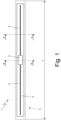
- the transponder 1 is inserted into a rubber sleeve 5, comprising two strips 6 and 7 of green rubber superimposed and pressed one against the other (preferably, the rubber of the two rubber strips 6 and 7 is initially green and is vulcanized together with the rest of the pneumatic tyre during the final vulcanization of the pneumatic tyre itself); in general, the two strips 6 and 7 of green rubber of the sleeve 5 are 1-2 mm longer/wider than the transponder 1 (i.e., than the electronic circuit 2 and the antenna 3).
- the two strips 6 and 7 of green rubber are initially parallelepiped (but may also take a different form) and deform around the components of the transponder 1 when they are pressed one against the other around the transponder 1 itself.
- the two rubber strips 6 and 7 of the sleeve 5 are vulcanized from the beginning (i.e., the rubber of the two strips of rubber 6 is immediately vulcanized) or semi-vulcanized (or only partially vulcanized); the two rubber strips 6 and 7 could also have differing degrees of vulcanization therebetween (for example, the strip 6 could be of green rubber whilst the strip 7 could be of vulcanized rubber or semi-vulcanized rubber or vice versa).
- the support 4 is absent and its function is performed by the strips 6 and 7 of rubber of the sleeve 5.
- the thickness T of the sleeve 5 (containing the transponder 1 within the interior thereof) is between 0.3 and 2 mm, the width W of the sleeve 5 is approximately 8-12 mm, and the length L of the sleeve 5 is approximately 60-80 mm.
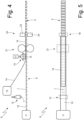
- the number 8 indicates a processing unit for inserting the transponders 1 into the corresponding rubber sleeves 5 in its entirety.
- the processing unit 8 comprises a conveyor 9 that advances a single rubber belt 10 arranged (for example horizontally) along a horizontal and straight insertion path; as described below, the rubber belt 10 is intended to form the strip 6 of each sleeve 5.
- the rubber belt 10 is fed to the conveyor 9 by means of a feed device 11 which could produce the rubber belt 10 by means of an extruder or else it could unwind the rubber belt 10 from a reel (wherein the rubber belt 10 is wound, for example by means of the interposition of a non-stick film that could be removed as the unwinding proceeds and that is generally reused after the eventual removal thereof).
- the processing unit 8 includes a feed device 12 that places each transponder 1 upon an upper surface of the rubber belt 10 and (approximately) at the center of the rubber belt 10; necessarily, each transponder 1 is placed upon the upper surface of the rubber belt 10 in such a way as to stay within the confines of the rubber belt 10 itself.
- each transponder 1 is transversely placed upon the upper surface of the rubber belt 10, i.e., with a longitudinal axis of the transponder 1 perpendicular to a longitudinal axis 10 of the rubber belt 10; according to an alternative embodiment, not shown, each transponder 1 is longitudinally placed upon the upper surface of the rubber belt 10, i.e., with the longitudinal axis of the transponder 1 parallel (and coaxial) to the longitudinal axis of the rubber belt 10.
- the feed device 12 could comprise a gripping head (suction or magnetic) that is suitable for picking up and holding a transponder 1 and a motorized arm that cyclically moves the gripping head between a pickup station, wherein the gripping head picks up a transponder 1, and a transfer station, wherein the gripping head places the transponder 1 upon the upper surface of the rubber belt 10.
- the gripping head of the feed device 12 can hold a transponder 1 by means of pneumatic suction or else by means of the magnetic attraction generated by an electromagnet.
- the feed device 12 places upon the upper surface of the rubber belt 10 a single transponder 1 at a time; according to a different embodiment, not shown, the feed device 12 places upon the upper surface of the rubber belt 10 several transponders 1 at a time (for example two, three, four, five... transponders 1 at a time).
- the processing unit 8 comprises a feed device 13 that is arranged downstream of the feed device 12 along the direction of travel of the rubber belt 10 and places upon the upper surface of the rubber belt 10, and above each previously placed transponder 1 a rubber belt 13; as described below, each rubber belt 13 is intended to form the strip 7 of each sleeve 5.
- the feed device 13 could produce the rubber belt 14 by means of an extruder or else it could unwind the rubber belt 14 from a reel (wherein the rubber belt 14 is wound, for example by means of the interposition of a non-stick film that could be removed as the unwinding proceeds and that is generally reused after the eventual removal thereof).
- the rubber belt 14 is slightly narrower than the underlying rubber belt 10, whilst, according to other embodiments that are not shown, the rubber belt 14 has exactly the same size as the rubber belt 10.
- Both of the rubber belts 10 and 14 can be made from green rubber, semi-vulcanized rubber or else from vulcanized rubber; if necessary the rubber that constitutes one rubber belt, 10 and 14, could be different (both as regards the degree of vulcanization and as regards the chemical composition) from the rubber that constitutes the other rubber belt 14 or 10.
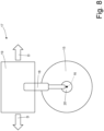
- the processing unit 8 comprises a pressure roller 15, which is arranged above the rubber belt 14, that is mounted idling in order to freely rotate around an axis of rotation 16 (shown in Figure 8 ) perpendicular to the insertion path, and that is cyclically moved back and forth along a direction D that is perpendicular to the axis of rotation 16 and that is parallel to the insertion path.
- the processing unit 8 comprises an actuator 17 that supports the pressure roller 15 in a rotatable manner (i.e., allowing the pressure roller 15 to rotate freely around the axis of rotation 16), that cyclically moves the pressure roller 15 along the direction D, and at the same time presses the pressure roller 15 against the underlying rubber belt 14 with a predetermined and constant force.
- the actuator 17 causes the pressure roller 15 to roll above the rubber belt 14 moving back and forth along the direction D in order to perform the "rolling" of the rubber belt 14 against the rubber belt 10 with the interposition of the transponder 1.
- the actuator 17 then causes the pressure roller 15 to roll over the rubber belt 14 downstream of the feed device 13 in order to press the rubber belt 14 against the rubber belt 10 and causing the pressure roller 15 to complete a forward stroke in one direction and a return stroke in the opposite direction.
- the actuator 17 comprises elastic means 18 (mechanical or pneumatic) which are interposed between a frame 19 of the actuator 17 and the bearings 20 that support the pressure roller 15; in this way the pressure roller 15 is always pressed, with the same predetermined and constant force, against the rubber belt 14, independent of the non-uniformities of the rubber belt 14 that are due to the alternating presence of the transponders 1.
- the predetermined force with which the pressure roller 15 is pressed against the rubber belt 14 depends upon the setting of the elastic means 18, and is therefore varied by means of adjusting the same elastic means 18.
- the pressure roller 15 is moved along the direction D, i.e., parallel to the insertion path, from a starting position (shown in Figure 5 ) wherein the pressure roller 15 is farther from the feed device 13, to an arrival position (shown in figure 7 ) wherein the pressure roller 15 is closer to the feed device 13, and is then moved in the opposite direction from the arrival position to the starting position; during this movement, the pressure roller 15 rolls over the rubber belt 14, pressing the rubber belt 14 itself against the rubber belt 10 with a predetermined and constant force.
- the pressure roller 15 is shown in Figure 6 when it is in an intermediate position between the starting position (shown in Figure 5 ) and the arrival position (shown in Figure 7 ).
- the "rolling” performed by the pressure roller 15 that moves back and forth along the direction D (i.e., from the starting position to the arrival position and vice versa) makes it possible for the rubber belt 14 to adhere, in an optimal way, to the underlying rubber belt 10 with the interposition of the transponder 1.
- the processing unit 8 comprises a compression device 21 that is arranged downstream of the feed device 13 and the pressure roller 15 along the direction of travel of the rubber belt 10 and is suitable for pressing the rubber belt 14 against the rubber belt 10 (with the interposition of the corresponding transponder 1).
- the compression device 21 comprises at least one pair of pressure rollers cooperating therebetween, wherein the rubber belts 10 and 14 are passed therebetween.
- the processing unit 8 comprises a cutting device 22 that is arranged downstream of the compression device 21 along the direction of travel of the rubber belt 10 and that is suitable for cutting the rubber belts 10 and 14 in performing a perimeter cut of a rectangular shape around each transponder 1 in order to separate the sleeves 5 containing the respective transponders 1 from the rubber belts 10 and 14.
- the cutting device 22 comprises a cutting head 23 carrying a rectangular blade (that is clearly internally hollow) and a counter head 24 that is aligned with the cutting head 23 and that is arranged on the other side of the rubber belts 10 and 14 in relation to the cutting head 23; the cutting head 23 is vertically movable, such as to approach and move away to/from the rubber belts 10 and 14 whilst the counter head 24 can be fixed, or else it can also be vertically movable, such as to approach and move away to/from the rubber belts 10 and 14.
- the cutting device 22 cuts out one transponder 1 at a time; according to a different embodiment not shown, the cutting device 22 cuts out several transponders 1 at a time (for example two, three, four, five... transponders 1 at a time).
- the conveyor 9 moves the rubber belt 10 according to an intermittent law of motion (i.e., step-by-step) that envisages a cyclic alternation of motion phases, during which the rubber belt 10 is advanced, and stop phases, during which the rubber belt 10 remains stationary. All of the processing (the feeding of the transponder 1, the application of the rubber belt 14 by means of the pressure roller 15, the cutting out of the sleeves 5) is executed when the rubber belt 10 is stationary (i.e. during the stop phases) and is suspended when the rubber belt 10 is in motion (i.e., during the motion phases).
- an intermittent law of motion i.e., step-by-step
- the processing unit 8 described above has many advantages.
- the processing unit 8 described above is particularly simple and economical to implement insofar as it envisages the execution of only a few easily automated operations.
- the insertion method described above makes it possible to insert a transponder 1 into the sleeve 5, whilst always ensuring high precision, insofar as each rubber belt 14 is placed upon the upper surface of the rubber belt 10 and upon the corresponding transponders 1 when the rubber belt 10 is stationary.
Landscapes
- Engineering & Computer Science (AREA)
- Mechanical Engineering (AREA)
- Chemical & Material Sciences (AREA)
- Composite Materials (AREA)
- Computer Hardware Design (AREA)
- Microelectronics & Electronic Packaging (AREA)
- Physics & Mathematics (AREA)
- General Physics & Mathematics (AREA)
- Theoretical Computer Science (AREA)
- Tyre Moulding (AREA)
- Transceivers (AREA)
Claims (12)
- Verarbeitungsverfahren zum Einsetzen von elektronischen Vorrichtungen (1), die für eine Hochfrequenzkommunikation geeignet sind, in jeweilige Kautschukhülsen (5), wobei jede davon zwei überlappende Streifen (6, 7) umfasst, die dazwischen eine entsprechende elektronische Vorrichtung (1), die für die Hochfrequenzkommunikation geeignet ist, umschließen; wobei das Verarbeitungsverfahren die Schritte umfasst zum:Vorwärtsbewegen eines ersten Kautschukbandes (10), das vorzugsweise horizontal entlang eines Einsetzweges mittels eines Förderers (9) angeordnet ist, wobei das erste Kautschukband (10) dazu gedacht ist, um einen ersten Streifen (6) von jeder Hülse (5) auszubilden;Platzieren der elektronischen Vorrichtungen (1), die für die Hochfrequenzkommunikation geeignet sind, auf einer oberen Oberfläche des ersten Kautschukbandes (10) mittels einer ersten Zuführvorrichtung (12);Platzieren, mittels einer zweiten Zuführvorrichtung (13), auf der oberen Oberfläche des ersten Kautschukbandes (10) und auf jeder elektronischen Vorrichtung (1), die für die Hochfrequenzkommunikation geeignet ist und vorher platziert wurde, eines zweiten Kautschukbandes (14), das die elektronischen Vorrichtungen (1), die für die Hochfrequenzkommunikation geeignet ist, vollständig bedeckt, wobei das zweite Kautschukband (14) dazu gedacht ist, um einen zweiten Streifen (7) von jeder Hülse (5) auszubilden;Ausschneiden, mittels einer Schneidvorrichtung (22), die stromabwärts der zweiten Zuführvorrichtung (13) entlang der Laufrichtung des ersten Kautschukbandes (10) angeordnet ist, der zwei Kautschukbänder (10, 14) durch Ausführen eines Umfangsschnitts um jede elektronische Vorrichtung (1) herum, die für die Hochfrequenzkommmunikation geeignet ist, um jede Hülse (5), die eine entsprechende elektronische Vorrichtung (1), die für die Hochfrequenzkommunkation geeignet ist, enthält, von den zwei Kautschukbändern (10, 14) zu trennen; undVeranlassen einer Druckrolle (15), um über das zweite Kautschukband (14) stromabwärts der zweiten Zuführvorrichtung (13) zu rollen, um das zweite Kautschukband (14) gegen das erste Kautschukband (10) zu drückenwobei das Verarbeitungsverfahren dadurch gekennzeichnet ist, dass die Druckrolle veranlasst wird, um einen Vorwärtshub in eine Richtung und einen Rückwärtshub in die entgegengesetzte Richtung zu beenden,der Förderer (9) das erste Kautschukband (10) gemäß einem intermittierenden Bewegungsgesetz vorwärts bewegt, das einen zyklischen Wechsel von Bewegungsphasen, während denen das erste Kautschukband (10) vorwärts bewegt wird, und Stillstandsphasen, während denen das erste Kautschukband (10) stationär bleibt, vorsieht; unddie Druckrolle (15) veranlasst wird, über das zweite Kautschukband (14) zu rollen, wenn das erste Kautschukband (10) stationär ist.
- Verarbeitungsverfahren nach Anspruch 1, wobei die Druckrolle (15) leerlaufend montiert ist, um sich frei um eine Drehachse (16) herum senkrecht zu dem Einsetzweg drehen zu können.
- Verarbeitungsverfahren nach Anspruch 1 oder 2, wobei die Druckrolle (15) entlang einer Richtung (D), die zu dem Einsetzweg parallel ist, zyklisch hin- und herbewegt wird.
- Verarbeitungsverfahren nach einem der Ansprüche 1 bis 3, wobei ein Aktor (17) vorgesehen ist, der die Druckrolle (15) auf drehbare Weise stützt, die Druckrolle (15) zyklisch bewegt und dabei die Druckrolle (15) mit einer zuvor bestimmten und konstanten Kraft gegen das darunterliegende Kautschukband (14) drückt.
- Verarbeitungsverfahren nach Anspruch 4, wobei der Aktor (17) elastische Mittel (18) umfasst, die zwischen einem Rahmen (19) des Aktors (17) und Lagern (20), die die Druckrolle (15) stützen, eingefügt sind.
- Verarbeitungsverfahren nach einem der Ansprüche 1 bis 5, wobei, wenn beide der Kautschukbänder (10, 14) stationär sind, die Druckrolle (15) von einer Ausgangsposition parallel zu dem Einsetzweg bewegt wird, wobei die Druckrolle (15) weiter von der zweiten Zuführvorrichtung (13) zu einer Ankunftsposition entfernt ist, wobei die Druckrolle (15) näher an der zweiten Zuführvorrichtung (13) ist, und dann in die entgegengesetzte Richtung von der Ankunftsposition zu der Ausgangsposition bewegt wird.
- Verarbeitungsverfahren nach einem der Ansprüche 1 bis 6, wobei die Schneidvorrichtung (22) einen Schneidkopf (23), der eine erste innen hohle Klinge trägt, und einen Gegenkopf (24), der mit dem Schneidkopf (23) ausgerichtet ist und der auf der anderen Seite des ersten Kautschukbandes (10) in Bezug auf den Schneidkopf (23) angeordnet ist, umfasst.
- Verarbeitungsverfahren nach einem der Ansprüche 1 bis 7, wobei die erste Zuführvorrichtung (12) umfasst:einen ersten Greifkopf, der zum Aufnehmen und Halten mindestens einer elektronischen Vorrichtung (1), die für die Hochfrequenzkommunikation geeignet ist, geeignet ist; undeinen motorisierten Arm, der den Greifkopf zwischen einer Aufnahmestation, wobei der Greifkopf eine elektronische Vorrichtung (1), die für die Hochfrequenzkommunikation geeignet ist, aufnimmt, und einer Übertragungsstation zyklisch bewegt, wobei der Greifkopf die elektronische Vorrichtung (1), die für die Hochfrequenzkommunikation geeignet ist, auf der oberen Oberfläche des ersten Kautschukbandes (10) platziert.
- Verarbeitungsverfahren nach einem der Ansprüche 1 bis 8 und umfassend den weiteren Schritt zum Aneinanderdrücken des ersten Kautschukbandes (10) und des zweiten Kautschukbandes (14) mittels einer Kompressionsvorrichtung (21), die zwischen der zweiten Zuführvorrichtung (13) und der Schneidvorrichtung (22) angeordnet ist.
- Verarbeitungsverfahren nach Anspruch 9, wobei die Kompressionsvorrichtung (21) ein Paar Druckrollen umfasst, die dazwischen zusammenwirken, wobei die Kautschukbänder (10, 14) dazwischen hindurchgeführt werden.
- Verarbeitungsverfahren nach einem der Ansprüche 1 bis 10, wobei die elektronische Vorrichtung (1), die für die Hochfrequenzkommunikation geeignet ist, geeignet ist, um in einen Luftreifen integriert zu werden.
- Verarbeitungseinheit (8) zum Einsetzen von elektronischen Vorrichtungen (1), die für die Hochfrequenzkommunikation geeignet sind, in jeweilige Kautschukhülsen (5), wobei jede davon zwei überlappende Streifen (6, 7) umfasst, die dazwischen eine entsprechende elektronische Vorrichtung (1), die für die Hochfrequenzkommunikation geeignet ist, umschließen; wobei die Verarbeitungseinheit (8) umfasst:einen Förderer (9) zum Vorwärtsbewegen eines ersten Kautschukbandes (10), der vorzugsweise horizontal entlang eines Einsetzweges angeordnet ist, wobei das erste Kautschukband (10) dazu gedacht ist, um einen ersten Streifen (6) von jeder Hülse (5) auszubilden;eine erste Zuführvorrichtung (12) zum Platzieren der elektronischen Vorrichtung (1), die für die Funkfrequenzkommunikation geeignet ist, auf einer oberen Oberfläche des ersten Kautschukbandes (10);eine zweite Zuführvorrichtung (13) zum Platzieren auf der oberen Oberfläche des ersten Kautschukbandes (10), und über jede vorher positionierte elektronische Vorrichtung (1), die für die Hochfrequenzkommunikation geeignet ist, eines zweiten Kautschukbandes (14), der die elektronische Vorrichtung (1), die für die Hochfrequenzkommunikation geeignet ist, vollständig bedeckt, wobei das zweite Kautschukband (14) dazu gedacht ist, um einen zweiten Streifen (7) von jeder Hülse (5) auszubilden; eine Schneidvorrichtung (22), die stromabwärts der zweiten Zuführvorrichtung (13) entlang der Laufrichtung des ersten Kautschukbandes (10) angeordnet ist, um mindestens die zwei Kautschukbänder (10, 14) durch Ausführen eines Umfangsschnitts um jede elektronische Vorrichtung (1) herum, die für die Hochfrequenzkommunikation geeignet ist, zu schneiden, um jede Hülse (5), die eine entsprechende elektronische Vorrichtung (1), die für die Hochfrequenzkommunikation geeignet ist, enthält, von den zwei Kautschukbändern (10) zu trennen; undeine Druckrolle (15), die stromabwärts der zweiten Zuführeinrichtung (13) angeordnet ist; undeinen Aktor (17), der die Druckrolle (15) veranlasst, über das zweite Kautschukband (14) zu rollen, um das zweite Kautschukband (14) gegen das erste Kautschukband (10) zu drückenwobei die Verarbeitungseinheit (8) dadurch gekennzeichnet ist, dass:der Aktor ferner die Druckrolle (15) veranlasst, einen Vorwärtshub in eine Richtung und einen Rückwärtshub in die entgegengesetzte Richtung zu beenden, und dadurch, dassder Förderer (9) zum Vorwärtsbewegen des ersten Kautschukbandes (10) gemäß einem intermittierenden Bewegungsgesetz geeignet ist, das einen zyklischen Wechsel von Bewegungsphasen, während denen das erste Kautschukband (10) vorwärts bewegt wird, und Stillstandsphasen, während denen das erste Kautschukband (10) stationär bleibt, vorsieht; unddie Druckrolle (15) geeignet ist, veranlasst zu werden, über das zweite Kautschukband (14) zu rollen, wenn das erste Kautschukband (10) stationär ist.
Applications Claiming Priority (1)
| Application Number | Priority Date | Filing Date | Title |
|---|---|---|---|
| IT102019000009990A IT201900009990A1 (it) | 2019-06-25 | 2019-06-25 | Metodo ed unita' di lavorazione per inserire dei dispositivi elettronici atti a comunicare in radiofrequenza in rispettive custodie di gomma |
Publications (2)
| Publication Number | Publication Date |
|---|---|
| EP3756870A1 EP3756870A1 (de) | 2020-12-30 |
| EP3756870B1 true EP3756870B1 (de) | 2024-11-20 |
Family
ID=68343231
Family Applications (1)
| Application Number | Title | Priority Date | Filing Date |
|---|---|---|---|
| EP20181610.5A Active EP3756870B1 (de) | 2019-06-25 | 2020-06-23 | Verfahren und vorrichtung zum einfügen einer elektronischen vorrichtung, die für radiofrequenz-kommunikation geeignet ist, in gummihülsen |
Country Status (5)
| Country | Link |
|---|---|
| EP (1) | EP3756870B1 (de) |
| ES (1) | ES3007335T3 (de) |
| HU (1) | HUE069538T2 (de) |
| IT (1) | IT201900009990A1 (de) |
| PL (1) | PL3756870T3 (de) |
Families Citing this family (8)
| Publication number | Priority date | Publication date | Assignee | Title |
|---|---|---|---|---|
| IT202100027812A1 (it) * | 2021-10-29 | 2023-04-29 | Bridgestone Europe Nv Sa | Metodo di produzione di uno pneumatico provvisto di un dispositivo elettronico |
| CN118234613A (zh) | 2021-11-09 | 2024-06-21 | 米其林集团总公司 | 用于连续制造半成品的系统 |
| WO2023083805A1 (en) | 2021-11-09 | 2023-05-19 | Compagnie Generale Des Etablissements Michelin | Process for manufacturing semi-finished products |
| FR3130683B1 (fr) | 2021-12-16 | 2023-11-03 | Michelin & Cie | Enroulement de fin de ligne pour composant de pneumatique |
| DE102022200103A1 (de) | 2022-01-07 | 2023-07-13 | Continental Reifen Deutschland Gmbh | Vorrichtung zum Herstellen von Reifeninnenschichten |
| JP7806503B2 (ja) * | 2022-01-12 | 2026-01-27 | 住友ゴム工業株式会社 | 重荷重用空気入りタイヤ |
| CN116924129A (zh) * | 2022-03-29 | 2023-10-24 | 北京小米移动软件有限公司 | 供料系统 |
| DE102022124337A1 (de) | 2022-09-22 | 2024-03-28 | Karl Eugen Fischer Gesellschaft mit beschränkter Haftung | Verfahren zur Herstellung vereinzelter streifenförmiger Laminatbauteile enthaltend ein zwischen zwei Laminatschichten aus einem bandförmigen, klebrigen Material eingebettetes elektronisches Bauteil, sowie Vorrichtung zur Herstellung solcher Laminatbauteile |
Family Cites Families (2)
| Publication number | Priority date | Publication date | Assignee | Title |
|---|---|---|---|---|
| FR2932711B1 (fr) * | 2008-06-23 | 2012-01-20 | Michelin Soc Tech | Procede et installation de fabrication d'un composant electronique enrobe de gomme. |
| JP5422439B2 (ja) * | 2010-02-26 | 2014-02-19 | 三菱重工業株式会社 | プリプレグ積層ヘッド及びこれを備えたプリプレグ自動積層装置 |
-
2019
- 2019-06-25 IT IT102019000009990A patent/IT201900009990A1/it unknown
-
2020
- 2020-06-23 HU HUE20181610A patent/HUE069538T2/hu unknown
- 2020-06-23 PL PL20181610.5T patent/PL3756870T3/pl unknown
- 2020-06-23 EP EP20181610.5A patent/EP3756870B1/de active Active
- 2020-06-23 ES ES20181610T patent/ES3007335T3/es active Active
Also Published As
| Publication number | Publication date |
|---|---|
| IT201900009990A1 (it) | 2020-12-25 |
| HUE069538T2 (hu) | 2025-03-28 |
| ES3007335T3 (en) | 2025-03-19 |
| PL3756870T3 (pl) | 2025-02-10 |
| EP3756870A1 (de) | 2020-12-30 |
Similar Documents
| Publication | Publication Date | Title |
|---|---|---|
| EP3756870B1 (de) | Verfahren und vorrichtung zum einfügen einer elektronischen vorrichtung, die für radiofrequenz-kommunikation geeignet ist, in gummihülsen | |
| EP3962721B1 (de) | Verfahrensmethode zum einbringen von elektronischen vorrichtungen, die zur kommunikation mit radiofrequenzen geeignet sind, in zugehörige gummihüllen | |
| ES2937237T3 (es) | Dispositivo de corte de etiqueta electrónica | |
| RU2760543C1 (ru) | Устройство для ламинирования электронной rfid-метки, используемой в шине | |
| EP2957531B1 (de) | Datenverwaltungsverfahren | |
| EP3141382A1 (de) | Verfahren und vorrichtung zum giessen eines zylinderförmigen elements | |
| US10628719B2 (en) | Apparatus, method and device for making products incorporating an RFid | |
| US11615283B2 (en) | System and method for producing a strip of material with an integrated electronic component | |
| RU2808041C2 (ru) | Способ для вставления электронных устройств, приспособленных для связи на радиочастоте, в соответствующие резиновые кожухи | |
| US20250010533A1 (en) | System for continuous manufacturing of semi-finished products | |
| CN112488276A (zh) | 一种rfid电子标签复合成型工艺 | |
| EP4422854B1 (de) | Verfahren zur herstellung eines reifens mit einer elektronischen vorrichtung | |
| EP4407512A1 (de) | Rfid-behälter und herstellungsverfahren für rfid-behälter | |
| US20250001662A1 (en) | Process for manufacturing semi-finished products | |
| EP3154329B1 (de) | Vorrichtung, verfahren und einrichtung zur herstellung von produkten mit rfid | |
| JP2025094496A (ja) | 電子タグ被覆装置及び電子タグ被覆方法 | |
| JP2023082846A (ja) | Rfidタグピッチ変換装置 |
Legal Events
| Date | Code | Title | Description |
|---|---|---|---|
| PUAI | Public reference made under article 153(3) epc to a published international application that has entered the european phase |
Free format text: ORIGINAL CODE: 0009012 |
|
| STAA | Information on the status of an ep patent application or granted ep patent |
Free format text: STATUS: THE APPLICATION HAS BEEN PUBLISHED |
|
| AK | Designated contracting states |
Kind code of ref document: A1 Designated state(s): AL AT BE BG CH CY CZ DE DK EE ES FI FR GB GR HR HU IE IS IT LI LT LU LV MC MK MT NL NO PL PT RO RS SE SI SK SM TR |
|
| AX | Request for extension of the european patent |
Extension state: BA ME |
|
| STAA | Information on the status of an ep patent application or granted ep patent |
Free format text: STATUS: REQUEST FOR EXAMINATION WAS MADE |
|
| 17P | Request for examination filed |
Effective date: 20210624 |
|
| RBV | Designated contracting states (corrected) |
Designated state(s): AL AT BE BG CH CY CZ DE DK EE ES FI FR GB GR HR HU IE IS IT LI LT LU LV MC MK MT NL NO PL PT RO RS SE SI SK SM TR |
|
| RAP3 | Party data changed (applicant data changed or rights of an application transferred) |
Owner name: BRIDGESTONE EUROPE NV/SA |
|
| GRAP | Despatch of communication of intention to grant a patent |
Free format text: ORIGINAL CODE: EPIDOSNIGR1 |
|
| STAA | Information on the status of an ep patent application or granted ep patent |
Free format text: STATUS: GRANT OF PATENT IS INTENDED |
|
| RIC1 | Information provided on ipc code assigned before grant |
Ipc: B29D 30/00 20060101ALN20240515BHEP Ipc: B29L 30/00 20060101ALN20240515BHEP Ipc: G06K 19/077 20060101ALI20240515BHEP Ipc: B29C 70/70 20060101ALI20240515BHEP Ipc: B29C 70/50 20060101AFI20240515BHEP |
|
| INTG | Intention to grant announced |
Effective date: 20240613 |
|
| GRAS | Grant fee paid |
Free format text: ORIGINAL CODE: EPIDOSNIGR3 |
|
| GRAA | (expected) grant |
Free format text: ORIGINAL CODE: 0009210 |
|
| STAA | Information on the status of an ep patent application or granted ep patent |
Free format text: STATUS: THE PATENT HAS BEEN GRANTED |
|
| AK | Designated contracting states |
Kind code of ref document: B1 Designated state(s): AL AT BE BG CH CY CZ DE DK EE ES FI FR GB GR HR HU IE IS IT LI LT LU LV MC MK MT NL NO PL PT RO RS SE SI SK SM TR |
|
| REG | Reference to a national code |
Ref country code: GB Ref legal event code: FG4D |
|
| REG | Reference to a national code |
Ref country code: CH Ref legal event code: EP |
|
| REG | Reference to a national code |
Ref country code: DE Ref legal event code: R096 Ref document number: 602020041554 Country of ref document: DE |
|
| REG | Reference to a national code |
Ref country code: IE Ref legal event code: FG4D |
|
| REG | Reference to a national code |
Ref country code: ES Ref legal event code: FG2A Ref document number: 3007335 Country of ref document: ES Kind code of ref document: T3 Effective date: 20250319 |
|
| REG | Reference to a national code |
Ref country code: LT Ref legal event code: MG9D |
|
| REG | Reference to a national code |
Ref country code: NL Ref legal event code: MP Effective date: 20241120 |
|
| REG | Reference to a national code |
Ref country code: HU Ref legal event code: AG4A Ref document number: E069538 Country of ref document: HU |
|
| P01 | Opt-out of the competence of the unified patent court (upc) registered |
Free format text: CASE NUMBER: APP_8762/2025 Effective date: 20250220 |
|
| PG25 | Lapsed in a contracting state [announced via postgrant information from national office to epo] |
Ref country code: IS Free format text: LAPSE BECAUSE OF FAILURE TO SUBMIT A TRANSLATION OF THE DESCRIPTION OR TO PAY THE FEE WITHIN THE PRESCRIBED TIME-LIMIT Effective date: 20250320 Ref country code: PT Free format text: LAPSE BECAUSE OF FAILURE TO SUBMIT A TRANSLATION OF THE DESCRIPTION OR TO PAY THE FEE WITHIN THE PRESCRIBED TIME-LIMIT Effective date: 20250320 Ref country code: HR Free format text: LAPSE BECAUSE OF FAILURE TO SUBMIT A TRANSLATION OF THE DESCRIPTION OR TO PAY THE FEE WITHIN THE PRESCRIBED TIME-LIMIT Effective date: 20241120 |
|
| PG25 | Lapsed in a contracting state [announced via postgrant information from national office to epo] |
Ref country code: FI Free format text: LAPSE BECAUSE OF FAILURE TO SUBMIT A TRANSLATION OF THE DESCRIPTION OR TO PAY THE FEE WITHIN THE PRESCRIBED TIME-LIMIT Effective date: 20241120 Ref country code: NL Free format text: LAPSE BECAUSE OF FAILURE TO SUBMIT A TRANSLATION OF THE DESCRIPTION OR TO PAY THE FEE WITHIN THE PRESCRIBED TIME-LIMIT Effective date: 20241120 |
|
| REG | Reference to a national code |
Ref country code: AT Ref legal event code: MK05 Ref document number: 1743207 Country of ref document: AT Kind code of ref document: T Effective date: 20241120 |
|
| PG25 | Lapsed in a contracting state [announced via postgrant information from national office to epo] |
Ref country code: BG Free format text: LAPSE BECAUSE OF FAILURE TO SUBMIT A TRANSLATION OF THE DESCRIPTION OR TO PAY THE FEE WITHIN THE PRESCRIBED TIME-LIMIT Effective date: 20241120 |
|
| PG25 | Lapsed in a contracting state [announced via postgrant information from national office to epo] |
Ref country code: NO Free format text: LAPSE BECAUSE OF FAILURE TO SUBMIT A TRANSLATION OF THE DESCRIPTION OR TO PAY THE FEE WITHIN THE PRESCRIBED TIME-LIMIT Effective date: 20250220 |
|
| PG25 | Lapsed in a contracting state [announced via postgrant information from national office to epo] |
Ref country code: AT Free format text: LAPSE BECAUSE OF FAILURE TO SUBMIT A TRANSLATION OF THE DESCRIPTION OR TO PAY THE FEE WITHIN THE PRESCRIBED TIME-LIMIT Effective date: 20241120 Ref country code: LV Free format text: LAPSE BECAUSE OF FAILURE TO SUBMIT A TRANSLATION OF THE DESCRIPTION OR TO PAY THE FEE WITHIN THE PRESCRIBED TIME-LIMIT Effective date: 20241120 Ref country code: GR Free format text: LAPSE BECAUSE OF FAILURE TO SUBMIT A TRANSLATION OF THE DESCRIPTION OR TO PAY THE FEE WITHIN THE PRESCRIBED TIME-LIMIT Effective date: 20250221 |
|
| PG25 | Lapsed in a contracting state [announced via postgrant information from national office to epo] |
Ref country code: RS Free format text: LAPSE BECAUSE OF FAILURE TO SUBMIT A TRANSLATION OF THE DESCRIPTION OR TO PAY THE FEE WITHIN THE PRESCRIBED TIME-LIMIT Effective date: 20250220 |
|
| PG25 | Lapsed in a contracting state [announced via postgrant information from national office to epo] |
Ref country code: SM Free format text: LAPSE BECAUSE OF FAILURE TO SUBMIT A TRANSLATION OF THE DESCRIPTION OR TO PAY THE FEE WITHIN THE PRESCRIBED TIME-LIMIT Effective date: 20241120 |
|
| PGFP | Annual fee paid to national office [announced via postgrant information from national office to epo] |
Ref country code: PL Payment date: 20250525 Year of fee payment: 6 Ref country code: DE Payment date: 20250520 Year of fee payment: 6 |
|
| PG25 | Lapsed in a contracting state [announced via postgrant information from national office to epo] |
Ref country code: DK Free format text: LAPSE BECAUSE OF FAILURE TO SUBMIT A TRANSLATION OF THE DESCRIPTION OR TO PAY THE FEE WITHIN THE PRESCRIBED TIME-LIMIT Effective date: 20241120 |
|
| PG25 | Lapsed in a contracting state [announced via postgrant information from national office to epo] |
Ref country code: EE Free format text: LAPSE BECAUSE OF FAILURE TO SUBMIT A TRANSLATION OF THE DESCRIPTION OR TO PAY THE FEE WITHIN THE PRESCRIBED TIME-LIMIT Effective date: 20241120 |
|
| PGFP | Annual fee paid to national office [announced via postgrant information from national office to epo] |
Ref country code: HU Payment date: 20250613 Year of fee payment: 6 Ref country code: FR Payment date: 20250520 Year of fee payment: 6 |
|
| PG25 | Lapsed in a contracting state [announced via postgrant information from national office to epo] |
Ref country code: RO Free format text: LAPSE BECAUSE OF FAILURE TO SUBMIT A TRANSLATION OF THE DESCRIPTION OR TO PAY THE FEE WITHIN THE PRESCRIBED TIME-LIMIT Effective date: 20241120 |
|
| PG25 | Lapsed in a contracting state [announced via postgrant information from national office to epo] |
Ref country code: SK Free format text: LAPSE BECAUSE OF FAILURE TO SUBMIT A TRANSLATION OF THE DESCRIPTION OR TO PAY THE FEE WITHIN THE PRESCRIBED TIME-LIMIT Effective date: 20241120 |
|
| PG25 | Lapsed in a contracting state [announced via postgrant information from national office to epo] |
Ref country code: CZ Free format text: LAPSE BECAUSE OF FAILURE TO SUBMIT A TRANSLATION OF THE DESCRIPTION OR TO PAY THE FEE WITHIN THE PRESCRIBED TIME-LIMIT Effective date: 20241120 |
|
| PG25 | Lapsed in a contracting state [announced via postgrant information from national office to epo] |
Ref country code: IT Free format text: LAPSE BECAUSE OF FAILURE TO SUBMIT A TRANSLATION OF THE DESCRIPTION OR TO PAY THE FEE WITHIN THE PRESCRIBED TIME-LIMIT Effective date: 20241120 |
|
| REG | Reference to a national code |
Ref country code: DE Ref legal event code: R097 Ref document number: 602020041554 Country of ref document: DE |
|
| PG25 | Lapsed in a contracting state [announced via postgrant information from national office to epo] |
Ref country code: SE Free format text: LAPSE BECAUSE OF FAILURE TO SUBMIT A TRANSLATION OF THE DESCRIPTION OR TO PAY THE FEE WITHIN THE PRESCRIBED TIME-LIMIT Effective date: 20241120 |
|
| PLBE | No opposition filed within time limit |
Free format text: ORIGINAL CODE: 0009261 |
|
| STAA | Information on the status of an ep patent application or granted ep patent |
Free format text: STATUS: NO OPPOSITION FILED WITHIN TIME LIMIT |
|
| PGFP | Annual fee paid to national office [announced via postgrant information from national office to epo] |
Ref country code: ES Payment date: 20250701 Year of fee payment: 6 |
|
| 26N | No opposition filed |
Effective date: 20250821 |
|
| REG | Reference to a national code |
Ref country code: CH Ref legal event code: H13 Free format text: ST27 STATUS EVENT CODE: U-0-0-H10-H13 (AS PROVIDED BY THE NATIONAL OFFICE) Effective date: 20260127 |
|
| PG25 | Lapsed in a contracting state [announced via postgrant information from national office to epo] |
Ref country code: MC Free format text: LAPSE BECAUSE OF FAILURE TO SUBMIT A TRANSLATION OF THE DESCRIPTION OR TO PAY THE FEE WITHIN THE PRESCRIBED TIME-LIMIT Effective date: 20241120 |
|
| PG25 | Lapsed in a contracting state [announced via postgrant information from national office to epo] |
Ref country code: LU Free format text: LAPSE BECAUSE OF NON-PAYMENT OF DUE FEES Effective date: 20250623 |
|
| GBPC | Gb: european patent ceased through non-payment of renewal fee |
Effective date: 20250623 |
|
| REG | Reference to a national code |
Ref country code: BE Ref legal event code: MM Effective date: 20250630 |